


KD-BT11J
JVC KD-BT11J, KD-BT11E, KD-BT11EU, KD-BT11U, KD-BT11EE Service Manual
...
SERVICE MANUAL
CD RECEIVER
MA387<Rev.003>20089SERVICE MANUAL
KD-BT11J, KD-BT11E, KD-BT11EX,
KD-BT11EY, KD-BT11EU, KD-BT11EE,
KD-BT11U, KD-BT11UT, KD-BT19UR,
KD-BT12E, KD-BT12EX
for J/U/UT/UR
for
E/EX/EY/EU/EE
COPYRIGHT © 2008 Victor Company of Japan, Limited
Lead free solder used in the board (material : Sn-Ag-Cu, melting point : 219 Centigrade)
Lead free solder used in the board (material : Sn-Cu, melting point : 230 Centigrade)
TABLE OF CONTENTS
1 PRECAUTION. . . . . . . . . . . . . . . . . . . . . . . . . . . . . . . . . . . . . . . . . . . . . . . . . . . . . . . . . . . . . . . . . . . . . . . . . 1-6
2 SPECIFIC SERVICE INSTRUCTIONS. . . . . . . . . . . . . . . . . . . . . . . . . . . . . . . . . . . . . . . . . . . . . . . . . . . . . . 1-9
3 DISASSEMBLY . . . . . . . . . . . . . . . . . . . . . . . . . . . . . . . . . . . . . . . . . . . . . . . . . . . . . . . . . . . . . . . . . . . . . . . 1-9
4 ADJUSTMENT . . . . . . . . . . . . . . . . . . . . . . . . . . . . . . . . . . . . . . . . . . . . . . . . . . . . . . . . . . . . . . . . . . . . . . . 1-25
5 TROUBLESHOOTING . . . . . . . . . . . . . . . . . . . . . . . . . . . . . . . . . . . . . . . . . . . . . . . . . . . . . . . . . . . . . . . . . 1-26
for EE
for J/UR
COPYRIGHT © 2008 Victor Company of Japan, Limited
No.MA387<Rev.003>
2008/9

SPECIFICATION
J / UR
AUDIO AMPLIFIER SECTION
Power Output 20 W RMS × 4 Channels at 4 Ω and < or = 1% THD+N
Signal-to-Noise Ratio 80 dBA (reference: 1 W into 4 Ω)
Load Impedance 4 Ω (4 Ω to 8 Ω allowance)
Tone Control Range Bass ±12 dB (60 Hz, 80 Hz, 100 Hz, 200 Hz)
Mid-range ±12 dB (500 Hz, 1.0 kHz, 1.5 kHz, 2.5 kHz)
Treble ±12 dB (10.0 kHz 12.5 kHz 15.0 kHz 17.5 kHz)
Q Bass: Q1.0, Q1.25, Q 1.5, Q2.0
Mid-range: Q0.5, Q0.75, Q1.0, Q1.25
Frequency Response 40 Hz to 20 000 Hz
Line-Out Level/Impedance 2.5 V/20 kΩ load (full scale)
Subwoofer-Out Level/Impedance 2.5 V /20 kΩ load (full scale)
Output Impedance 1 kΩ
Other Terminal CD changer jack AUX (auxiliary) input jack Antenna input
TUNER SECTION
Frequency Range FM
AM with channel interval set to 10 kHz: 530 kHz to 1 710 kHz
FM Tuner Usable Sensitivity 11.3 dBf (1.0 µV/75 Ω)
50 dB Quieting Sensitivity 16.3 dBf (1.8 µV/75 Ω)
Alternate Channel Selectivity (400 kHz)
Frequency Response 40 Hz to 15 000 Hz
Stereo Separation 35 dB
AM Tuner Sensitivity 20 µV
Selectivity 35 dB
CD PLAYER SECTION
Type Compact disc player
Signal Detection System Non-contact optical pickup (semiconductor laser)
Number of Channels 2 channels (stereo)
Frequency Response 5 Hz to 20 000 Hz
Dynamic Range 96 dB
Signal-to-Noise Ratio 98 dB
Wow and Flutter Less than measurable limit
MP3 Decoding Format (MPEG1/2 Audio Layer 3) Max. Bit Rate: 320 kbps
WMA (Windows Media® Audio) Decoding Format Max. Bit Rate: 192 kbps
Version Bluetooth 1.2 certified
Power Class Class 2 Radio (possible distance 10 m)
Service Area 10 m
Profile HFP 1.5, OPP 1.1, A2DP 1.2, AVRCP 1.3
Power Requirement Operating Voltage DC 14.4 V (11 V to 16 V allowance)
Grounding System Negative ground
Allowable Operating Temperature 0°C to +40°C (32°F to 104°F)
Dimensions (W × H × D)
(approx.)
Mass 1.3 kg (2.9 lbs) (excluding accessories)
Design and specifications are subject to change without notice.
Installation Size
Panel Size 188 mm × 58 mm × 6 mm (7-7/16” × 2-5/16” × 1/4”)
with channel inter val set to 100 k Hz or 200 kH z: 87.5 MH z to 107.9 MH z
with channel interval set to 50 kHz: 87.5 MHz to 108.0 MHz
with channel interval set to 9 kHz: 531 kHz to 1 602 kHz
65 dB
BLUETOOTH
GENERAL
182 mm × 52 mm × 160 mm (7-3/16” × 2-1/16” × 6-5/16”)
1-2 (No.MA387<Rev.003>)

E/EX/EY/EU
AUDIO AMPLIFIER SECTION
Maximum Power Output Front/Rear 50 W per channel
Continuous Power Output
(RMS)
Front/Rear 19 W per channel into 4 Ω, 40 Hz to 20 000 Hz at no more than 0.8%
total harmonic distortion.
Load Impedance 4 Ω (4 Ω to 8 Ω allowance)
Tone Control Range Bass ±12 dB (60 Hz, 80 Hz, 100 Hz, 200 Hz)
Mid-range ±12 dB (500 Hz, 1.0 kHz, 1.5 kHz, 2.5 kHz)
Treble ±12 dB (10.0 kHz 12.5 kHz 15.0 kHz 17.5 kHz)
Q Bass: Q1.0, Q1.25, Q 1.5, Q2.0
Mid-range: Q0.5, Q0.75, Q1.0, Q1.25
Frequency Response 40 Hz to 20 000 Hz
Signal-to-Noise Ratio 80 dB
Line-Out/Subwoofer-O ut Level/Impedance 2.5 V /20 kΩ load (full scale)
Output Impedance 1 kΩ
Other Terminal
CD changer jack Steering wheel remote input AUX (auxiliary) input jack Aerial input
TUNER SECTION
Frequency Range FM 87.5 MHz to 108.0 MHz
AM MW: 522 kHz to 1 620 kHz
LW: 144 kHz to 279 kHz
FM Tuner Usable Sensitivity 11.3 dBf (1.0 µV/75 Ω)
50 dB Quieting Sensitivity 16.3 dBf (1.8 µV/75 Ω)
Alternate Channel Sel ectivity (400 kHz )
65 dB
Frequency Response 40 Hz to 15 000 Hz
Stereo Separation 30 dB
MW Tuner Sensitivity/Selectivity 20 µV/35 dB
LW Tuner Sensitivity 50 µV
CD PLAYER SECTION
Type Compact disc player
Signal Detection System Non-contact optical pickup (semiconductor laser)
Number of Channels 2 channels (stereo)
Frequency Response 5 Hz to 20 000 Hz
Dynamic Range 96 dB
Signal-to-Noise Ratio 98 dB
Wow and Flutter Less than measurable limit
MP3 Decoding Format (MPEG1/2 Audio Layer 3) Max. Bit Rate: 320 kbps
WMA (Windows Media® Audio) Decoding Format Max. Bit Rate: 192 kbps
BLUETOOTH
Version Bluetooth 1.2 certified
Power Class Class 2 Radio (possible distance 10 m)
Service Area 10 m
Profile HFP 1.5, OPP 1.1, A2DP 1.2, AVRCP 1.3
GENERAL
Power Requirement Operating Voltage DC 14.4 V (11 V to 16 V allowance)
Grounding System Negat ive ground
Allowable Operating Temperature 0°C to +40°C
Dimensions (W × H × D)
(approx.)
Installation Size 182 mm × 52 mm × 160 mm
Panel Size 188 mm × 58 mm × 13 mm
Mass 1.3 kg (excluding accessor ies)
Design and specifications are subject to change without notice.
(No.MA387<Rev.003>)1-3

EE
AUDIO AMPLIFIER SECTION
Maximum Power Ou tput Front/Rear 50 W per channel
Continuous Power Output
(RMS)
Front/Rear 19 W per channel into 4 Ω, 40 Hz to 20 000 H z at no more than 0.8%
total harmonic distortion.
Load Impedance 4 Ω (4 Ω to 8 Ω allowance)
Tone Control Range Bass ±12 dB (60 Hz, 80 Hz, 100 Hz, 200 Hz)
Mid-range ±12 dB (500 Hz, 1.0 kHz, 1.5 kHz, 2.5 kHz)
Treble ±12 dB (10.0 kHz 12.5 kHz 15 .0 kHz 17.5 kHz)
Q Bass: Q1.0, Q1.25, Q 1.5, Q2.0
Mid-range: Q0.5, Q0.75, Q1.0, Q1.25
Frequency Response 40 Hz to 20 000 Hz
Signal-to-Noise Ratio 80 dB
Line-Out/Subwoofer-Out Level/Impedance 2.5 V /20 kΩ load (full scale)
Output Impedance 1 kΩ
Other Terminal AUX (auxiliary) input jack, Aerial input
TUNER SECTION
Frequency Range FM1/FM2 87.5 MHz to 108.0 MHz
FM3 65.00 MHz to 74.00 MHZ
AM MW: 522 kHz to 1 620 kHz
LW: 144 kHz to 279 kHz
FM Tuner Usable Sensitivity 11.3 dBf (1.0 µV/75 Ω)
50 dB Quieting Sensitivity 16.3 dBf (1.8 µV/75 Ω)
Alternate Channe l Selec tivity (40 0 kHz )
65 dB
Frequency Response 40 Hz to 15 000 Hz
Stereo Separation 30 dB
MW Tuner Sensitivity/Selectivity 20 µV/35 dB
LW Tuner Sensitivity: 50 µV
CD PLAYER SECTION
Type Compact disc player
Signal Detection System Non-contact optical pickup (semiconductor laser)
Number of Channels 2 channels (stereo)
Frequency Response 5 Hz to 20 000 Hz
Dynamic Range 96 dB
Signal-to-Noise Ratio 98 dB
Wow and Flutter Less than measurable limit
MP3 Decoding Format (MPEG1/2 Audio Layer 3) Max. Bit Rate: 320 kbps
WMA (Windows Media® Audio) Decoding Format Max. Bit Rate: 192 kbps
BLUETOOTH
Version Bluetooth 1.2 certified
Power Class Class 2 Radio (possible distance 10 m)
Service Area 10 m
Profile HFP 1.5, OPP 1.1, A2DP 1.2, AVRCP 1.3
GENERAL
Power Requirement Operating Voltage DC 14.4 V (11 V to 16 V allowance)
Grounding System Negative ground
Allowable Operating Temperature 0°C to +40°C
Dimensions (W × H × D)
(approx.)
Installation Size 182 mm × 52 mm × 160 mm
Panel Size 188 mm × 58 mm × 13 mm
Mass 1.3 kg (exclu ding accessories)
Design and specifications are subject to change without notice.
1-4 (No.MA387<Rev.003>)

U/UT
AUDIO AMPLIFIER SECTION
Maximum Power Output Front/Rear 50 W per channel
Continuous Power Output
(RMS)
Front/Rear 19 W per channel into 4 Ω, 40 Hz to 20 000 Hz at no more than 0.8%
total harmonic distortion.
Load Impedance 4 Ω (4 Ω to 8 Ω allowance)
Tone Control Range Bass ±12 dB (60 Hz, 80 Hz, 100 Hz, 200 Hz)
Mid-range ±12 dB (500 Hz, 1.0 kHz, 1.5 kHz, 2.5 kHz)
Treble ±12 dB (10.0 kHz 12.5 kHz 15.0 kHz 17.5 kHz)
Q Bass: Q1.0, Q1.25, Q 1.5, Q2.0
Mid-range: Q0.5, Q0.75, Q1.0, Q1.25
Frequency Response 40 Hz to 20 000 Hz
Signal-to-Noise Ratio 80 dB
Line-Out Level/Impedance 2.5 V/20 kΩ load (full scale)
Subwoofer-Out Level/Impedance 2.5 V /20 kΩ load (full scale)
Output Impedance 1 kΩ
Other Terminal CD changer jack AUX (auxiliary) input jack Antenna input
TUNER SECTION
Frequency Range FM 87.5 MHz to 108.0 MHz
AM 531 kHz to 1 602 kHz
FM Tuner Usable Sensitivity 11.3 dBf (1.0 µV/75 Ω)
50 dB Quieting Sensitivity 16.3 dBf (1.8 µV/75 Ω)
Alternate Channel Selectivity (400 kHz)
65 dB
Frequency Response 40 Hz to 15 000 Hz
Stereo Separation 35 dB
AM Tuner Sensitivity 20 µV
Selectivity 35 dB
CD PLAYER SECTION
Type Compact disc player
Signal Detection System Non-contact optical pickup (semiconductor laser)
Number of Channels 2 channels (stereo)
Frequency Response 5 Hz to 20 000 Hz
Dynamic Range 96 dB
Signal-to-Noise Ratio 98 dB
Wow and Flutter Less than measurable limit
MP3 Decoding Format (MPEG1/2 Audio Layer 3) Max. Bit Rate: 320 kbps
WMA (Windows Media® Audio) Decoding Format Max. Bit Rate: 192 kbps
BLUETOOTH
Version Bluetooth 1.2 certified
Power Class Class 2 Radio (possible distance 10 m)
Service Area 10 m
Profile HFP 1.5, OPP 1.1, A2DP 1.2, AVRCP 1.3
GENERAL
Power Requirement Operating Voltage DC 14.4 V (11 V to 16 V allowance)
Grounding System Negative groun d
Allowable Operating Temperature 0°C to +40°C
Dimensions (W × H × D)
(approx.)
Installation Size 182 mm × 52 mm × 160 mm
Panel Size 188 mm × 58 mm × 6 mm
Mass 1.3 kg (excluding accessories)
Design and specifications are subject to change without notice.
(No.MA387<Rev.003>)1-5
1.1 Safety Precautions
SECTION 1
PRECAUTION
!
!
Burrs formed during molding may be left over on some parts of the chassis. Therefore,
pay attention to such burrs in the case of preforming repair of this system.
Please use enough caution not to see the beam directly or touch it in case of an
adjustment or operation check.
1-6 (No.MA387<Rev.003>)
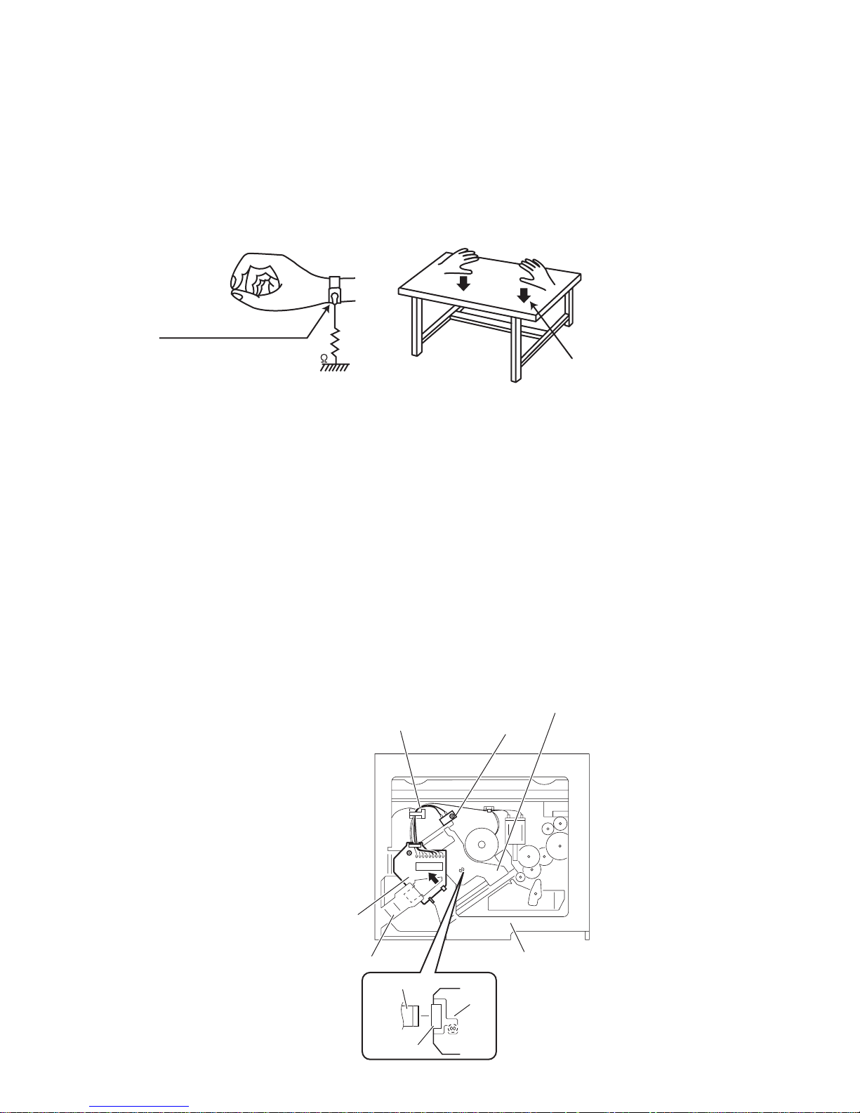
1.2 Preventing static electricity
Electrostatic discharge (ESD), w hi ch occurs w hen sta tic ele ct ricit y sto red i n the bod y, fa bric , etc. is discharged, ca n de stroy the laser
diode in the traverse unit (optical pickup). Take care to prevent this when performing repairs.
1.2.1 Grounding to prevent damage by static electricity
Static electricity in the work area can destroy the optical pickup (laser diode) in devices such as laser products.
Be careful to use proper grounding in the area where repairs are being performed.
(1) Ground the workbench
Ground the workbench by laying conductive material (such as a conductive sheet) or an iron plate over it before placing the
traverse unit (optical pickup) on it.
(2) Ground yourself
Use an anti-static wrist strap to release any static electricity built up in your body.
(caption)
Anti-static wrist strap
1M
Conductive material
(conductive sheet) or iron plate
(3) Handling the optical pickup
• In order to maintain quality during transport and before installation, both sides of the laser diode on the replacement optical
pickup are shorted. After replacement, return the shorted parts to their original condition.
(Refer to the text.)
• Do not use a tester to che ck the con dition of th e laser dio de in the opt ical pick up. The tes ter's internal power so urce can ea sily
destroy the laser diode.
1.3 Handling the traverse unit (optical pickup)
(1) Do not subject the traverse unit (optical pickup) to strong shocks, as it is a sensitive, complex unit.
(2) Cut off the shorted part of the flexible cable using nip pers, etc. afte r replacing th e optical pi ckup. For speci fic details, refe r to the
replacement procedure in th e t ext . R em ove the anti-static pin w he n re pla cing the traverse unit. Be c arefu l not to tak e to o l on g a
time when attaching it to the connector .
(3) Handle the flexible cable carefully as it may break when subjected to strong force.
(4) It is not possible to adjust the semi-fixed resistor that adjusts the laser power. Do not turn it.
1.4 Attention when traverse unit is decomposed
*Please refer to "Disassembly method" in the text for the pickup unit.
• Apply solder to the short land before the card wire is disconnected from the connector on the pickup unit.
(If the card wire is disconnected without applying solder, the pickup may be destroyed by static electricity.)
• In the assembly, be sure to remove solder from the short land after connecting the card wire.
Pickup
Wires
Push switch
Base board
Frame
Flexible wire
Connector
CD mechanism
assembly
Pickup
(No.MA387<Rev.003>)1-7
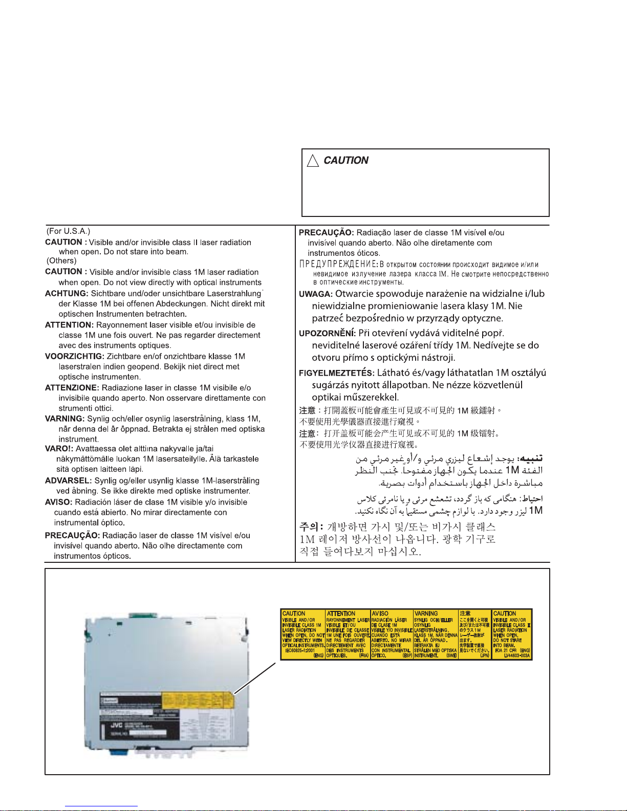
1.5 Important for laser products
1.CLASS 1 LASER PRODUCT
2.CAUTION :
(For U.S.A.) Visible and/or invisible class II laser radiation
when open. Do not stare into beam.
(Others) Visible and/or invisible class 1M laser radiation
when open. Do not view directly with optical instruments.
3.CAUTION : Visible and/or invisible laser radiation when
open and inter lock failed or defeated. Avoid direct
exposure to beam.
4.CAUTION : This laser product uses visible and/or invisible
laser radiation and is equipped with safety switches which
prevent emission of radiation when the drawer is open and
the safety interlocks have failed or are defeated. It is
dangerous to defeat the safety switches.
5.CAUTION : If safety switches malfunction, the laser is able
to function.
6.CAUTION : Use of controls, adjustments or performance of
procedures other than those specified here in may result in
hazardous radiation exposure.
!
Please use enough caution not to
see the beam directly or touch it
in case of an adjustment or operation
check.
REPRODUCTION AND POSITION OF LABELS and PRINT
WARNING LABEL and PRINT
1-8 (No.MA387<Rev.003>)
SECTION 2
SPECIFIC SERVICE INSTRUCTIONS
This service manual does not describe SPECIFIC SERVICE INSTRUCTIONS.
SECTION 3
DISASSEMBLY
3.1 Main body
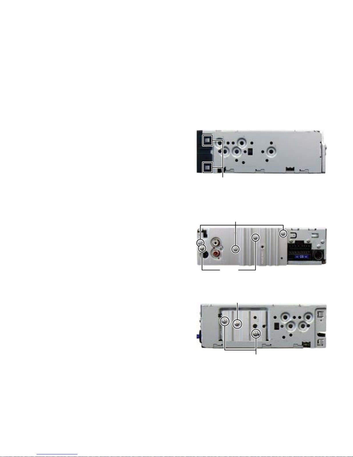
3.1.1 Removing the FRONT CHASSIS assembly (See Fig.1)
(1) Disengage the four hooks a engaged the both side of the
FRONT CHASSIS assembly.
hook
a
Fig.1
3.1.2 Removing the HEAT SINK (See Fig.2, 3)
(1) Remove the three screws A and the two screws B attaching
the HEAT SINK. (See Fig.2)
(2) Remove the two screws C and the one screw D attaching
the HEAT SINK. (See Fig.3)
A
B
Fig.2
D
C
Fig.3
(No.MA387<Rev.003>)1-9
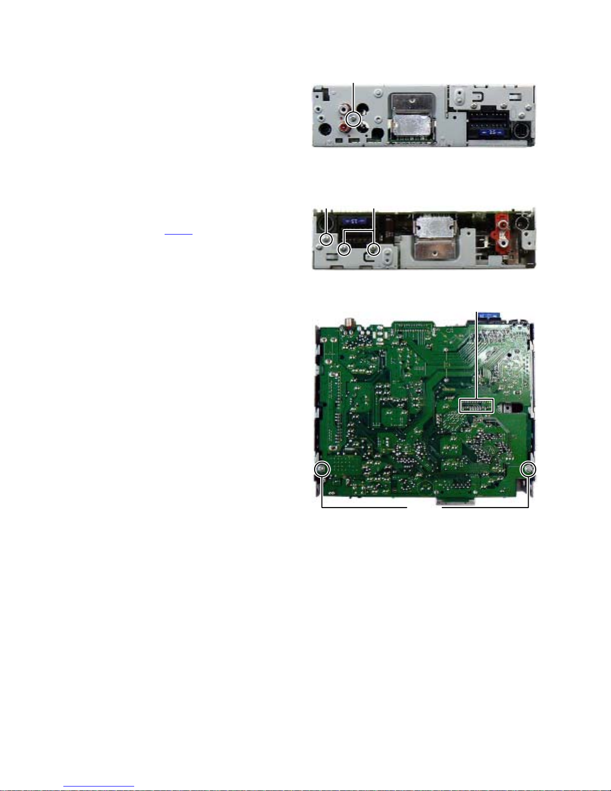
3.1.3 Removing the BOTTOM COVER (See Fig.4)
(1) Remove the one screw E attaching the BOTTOM COVER.
(2) Slide the BOTTOM COVER to backward.
3.1.4 Removing the MAIN BOARD assembly (See Fig.5, 6)
(1) Remove the two screws F and the one screw G attaching
the MAIN BOARD assembly. (See Fig.5)
(2) Remove the two screws H attaching the MAIN BOARD assembly.
(See Fig.6)
(3) Disconnect the connector CN501
BOARD assembly and CD MECHANISM assembly. (Se e
Fig.6)
connected to MAIN
E
Fig.4
FG
Fig.5
CN501
1-10 (No.MA387<Rev.003>)
H
Fig.6
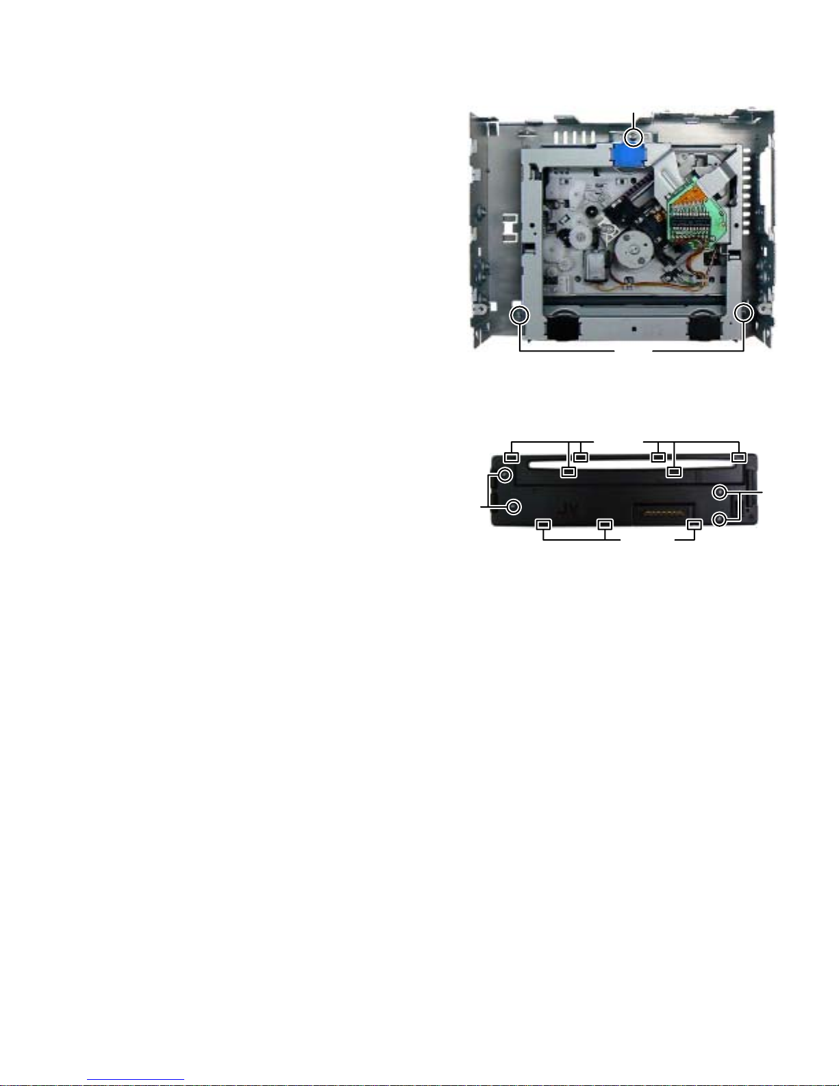
3.1.5 Removing the CD MECHANISM assembly (See Fig.7)
(1) Remove the three screws J attaching the CD MECHANISM
assembly.
3.1.6 Removing the SWITCH BOARD assembly (See Fig.8)
(1) Remove the VOLUME KNOB.
(2) Remove the four screws K attaching the REAR COVER.
(3) Disengage the nine hooks b engage d the REAR COVER.
Fig.7
hook
J
J
b
K
Fig.8
hook
K
b
(No.MA387<Rev.003>)1-11
3.2 CD mechanism assembly
A
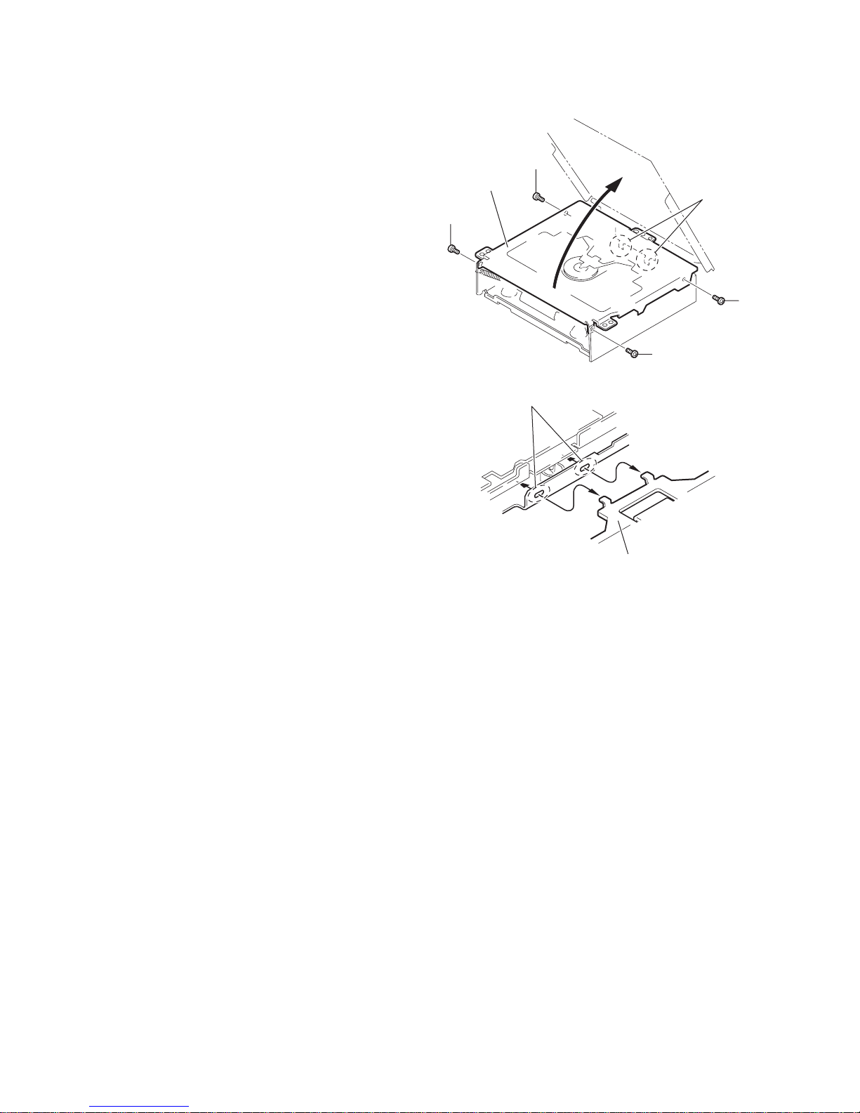
3.2.1 Removing the top cover
(See Figs.1 and 2)
(1) From the both side of the CD mechanism assembly, re-
move the four screws A attaching the top cover. (See
Fig.1.)
(2) Lift the front side of the top cover and move the top cover
backward to release the two joints a. (See Figs.1 and 2.)
Top cover
A
a
A
A
Fig.1
a
Top cover
Fig.2
1-12 (No.MA387<Rev.003>)
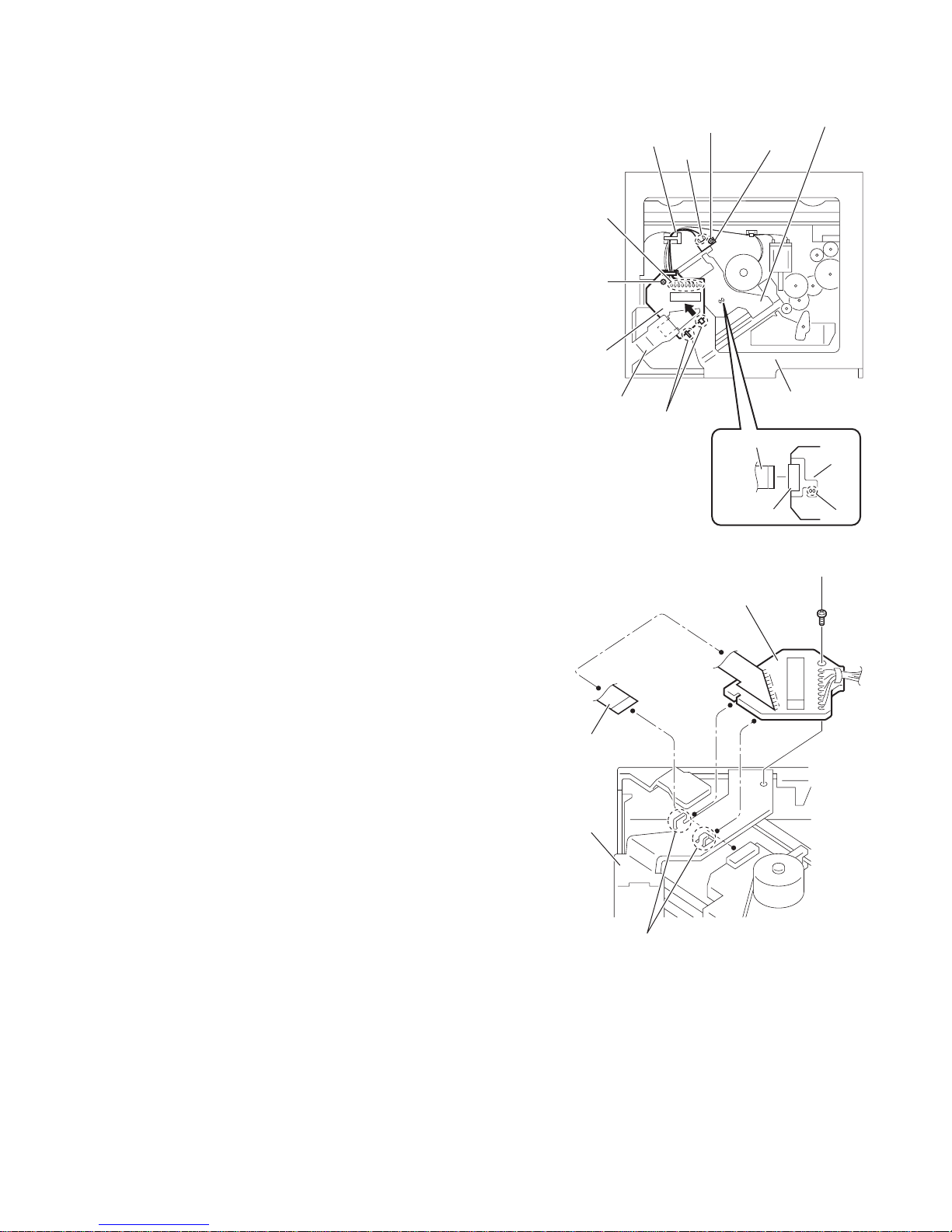
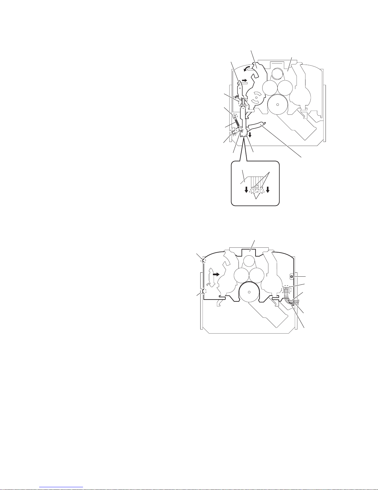
3.2.2 Removing the push switch
(See Figs.3)
(1) From the bottom side of the CD mechanism assembly, re-
move the screw B attaching the push switch.
(2) Take out the push switch from the CD mechanism assem-
bly.
Reference:
Remove the wires fro m solder ed sections b of the push sw itch
as required.
3.2.3 Removing the base board
(See Figs.3 and 4)
Caution:
Solder the short land c before the f lexib le wire is disc onnec ted
from the connector on the pic ku p. If the f lex ible wire is disconnected without applying solder, the pickup may be destroyed
by static electricity. (See Fig.3.)
(1) From the bottom side of the CD mechanism assembly, re-
move the scre w C attaching the base board. (See Figs.3
and 4.)
(2) Solder the short land c on the pickup. (See Fig.3.)
(3) Disconnect the flexible wire fr om the conne ctor on the pic k-
up. (See Fig.3.)
(4) Remove the base board from the joints d of the fram e in the
direction of the arrow. (See Figs.3 and 4.)
Reference:
Remove the wires from the soldered sections e on the base
board as required. (See Fig.3.)
Caution:
When reattaching the base board, be sure to remove solder
from the short land c after connecting the flexible wire. (See
Fig.3.)
e
C
Base board
Frame
Wires
B
b
d
Push switch
Flexible wire
Connector
Fig.3
Pickup
CD mechanism
assembly
Pickup
c
C
Base board
Flexible wire
Frame
d
Fig.4
(No.MA387<Rev.003>)1-13
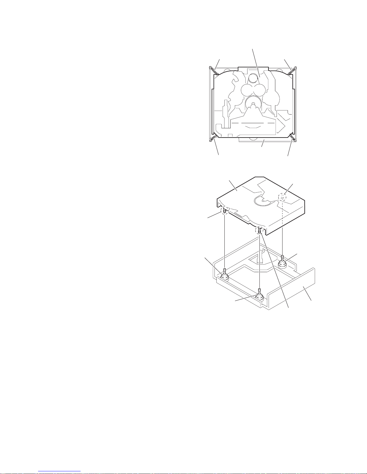
3.2.4 Removing the chassis unit
(See Figs.5 and 6)
• Remove the top cover and base board.
(1) From the top side of the CD mec hanism a ssembly, r emove
the front suspension springs and rear suspension springs
attaching the chassis unit to the frame. (See Fig.5.)
(2) Remove the chassis unit from the da mpers on the f rame in
an upward direction. (See Fig.6.)
Note:
• Pay attention to misuse and loss of each spring. (See Fi g.5.)
• When reassembling, make sure that the three shafts on the
underside of the chassis unit are inserted to the dampers
certainly. (See Fig.6.)
Chassis unit
Front suspension spring
Front suspension spring
Frame
Rear suspension spring Rear suspension spring
Fig.5
Chassis unit
Shaft
Shaft
Damper F
Damper F
Damper R
Frame
Shaft
Fig.6
1-14 (No.MA387<Rev.003>)
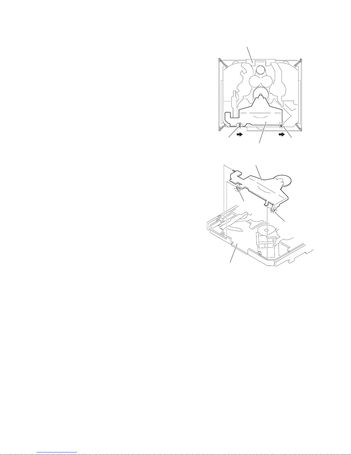
3.2.5 Removing the clamper assembly
(See Figs.7 and 8)
• Remove the top cover.
Move the clamper assembly in the direction of the arrow to release the joints f from the chassis unit.
Chassis unit
f
Clamper assembly
Clamper assembly
Chassis unit
f
Fig.7
f
f
Fig.8
(No.MA387<Rev.003>)1-15
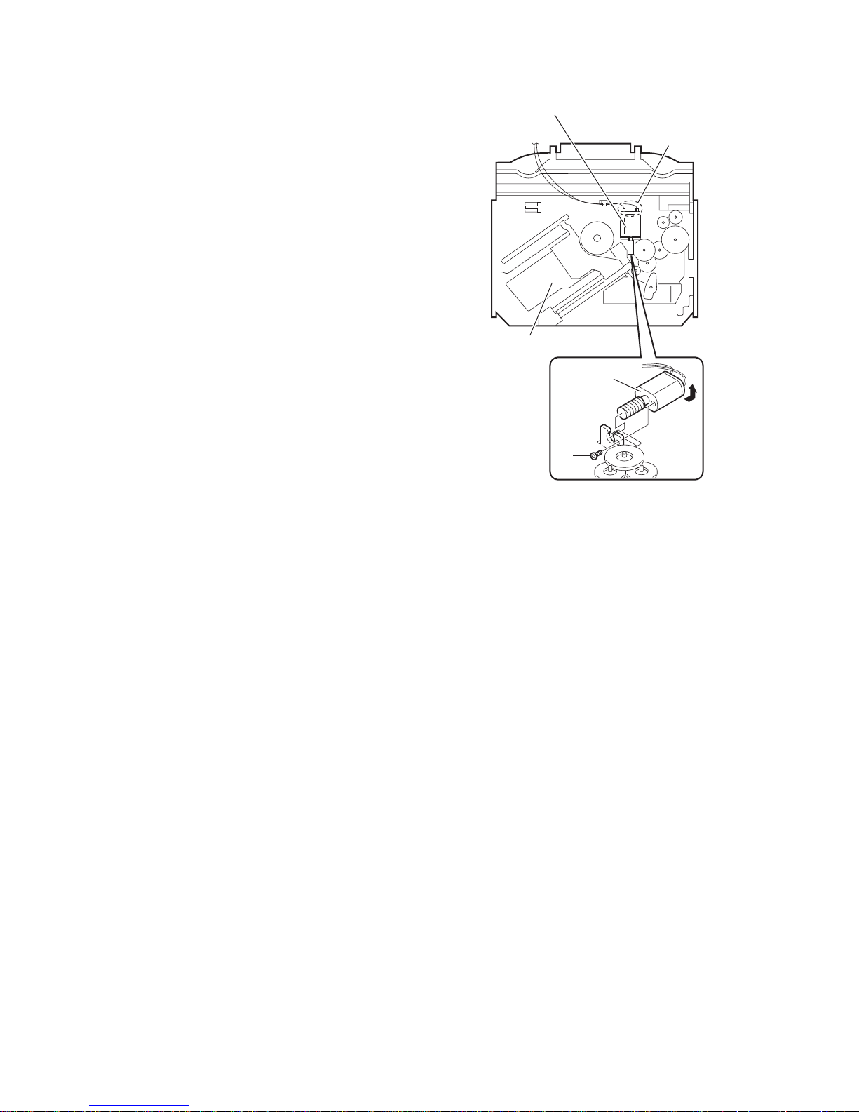
3.2.6 Removing the loading/feed motor assembly
(See Fig.9)
• Remove the top cover, base board and cha ss is unit.
From the bottom side of the chassis unit, remove the screw D
and take out the loading/feed motor assembly in the direction of
the arrow.
Reference:
Remove the wires from th e sold ered sec tions g of the lo ading /
feed motor assembly as required.
Loading/feed motor assembly
g
Chassis unit
Loading/feed
motor
assembly
D
Fig.9
1-16 (No.MA387<Rev.003>)
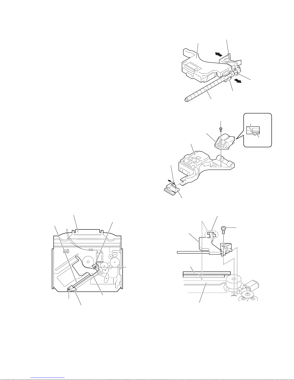
3.2.7 Removing the pickup
(See Figs.10 to 12)
• Remove the top cover, base board and chassis unit.
(1) From the bottom side of the chassis unit, remove the screw
E attaching the pu. shaf t ho lder B an d pull the pu . shaft out
of the pu. shaft holder A. (See Fig.10.)
(2) Remove the screw F attaching the pu. sh aft hol der A. (See
Fig.10.)
(3) Take out the pickup with pu. shaft holder A an d feed s crew
assembly from the chassis unit. (See Fig.11.)
(4) Remove the section h of the pu. shaft holder A in th e direc-
tion of the arrow. (See Fig.11.)
(5) Remove the feed screw assembly from the section j of the
pickup in the direction of the arrow. (See Fig.11.)
(6) Remove the screw G attaching the feed screw holder to the
pickup. (See Fig.12.)
Reference:
Remove the feed nut spring from the feed screw holder
as required. (See Fig.12.)
(7) Release th e c law k in the direction of the arrow to remove
the feed sub holder. (See Fig.12.)
Pickup
Feed screw assembly
Feed screw holder
Pu. shaft holder A
Fig.11
G
h
j
Feed screw
holder
3.2.8 Reattachi ng the picku p
(See Figs.10 to 13)
(1) Reattach the feed sub holder to the pickup. (See Fig.12.)
(2) Reattach the feed screw holder to the pickup using the
screw G. (See Fig.12.)
(3) Reattach the feed screw assembly and pu. shaft holder A
to the pickup as before. (See Fig.11.)
(4) Set the section m of the pickup to the rail of the chas sis unit
at first and attach the pickup to the chassis unit with the
screw F as before. (See Figs.10 and 13.)
(5) Attach the pu. shaft to the pickup as before. (See Fig.10.)
(6) Attach the pu. shaft holder B to the chassis unit with the
screw E as before. (See Fig.10.)
Chassis unit
Pu. shaft holder A
Pu. shaft
F
Pickup
k
Feed sub holder
Pickup
Rail
Feed nut
spring
Fig.12
m
F
Pickup
E
Pu. shaft holder B
Fig.10
Chassis unit
Fig.13
(No.MA387<Rev.003>)1-17
3.2.9 Removing the trigger arm
(See Fig.14)
• Remove the top cover, base board, chassis unit and clamper
assembly.
(1) From the top side of the chassis unit, remove the trigger
arm spring from the sections (n, p).
(2) From the bottom side of the chassis unit, release the claws
q of the trigger arm base in the directio n o f the arrow to remove them from the sections r of the chassis unit to the
other side.
Note:
When releasing the claws q, t ake care n ot to break th em.
(3) From the top side of the chassis unit, move the select arm
R and select lock arm in the direction of the arrow to remove the trigger arm base from the section s in the direction of the arrow.
(4) Remove the trigger arm from the section t.
3.2.10 Removing the top plate assembly
(See Fig.15)
• Remove the top cover, base board, chassis unit, clamper as-
sembly and trigger arm.
(1) Remove the screw H attaching the top plate assembly.
(2) Move the top plate assembly in the d irection of the arr ow to
release the joints (u, v).
Reference:
Remove the wires from the soldered sections w of the top plate
assembly as required.
Note:
When reassembling, solder the wires as before.
Select lock arm
Trigger arm
spring
u
v
Select arm R
s
n
t
p
Chassis unit
Top plate assembly
Chassis unit
Trigger arm base
Trigger arm
q
r
Fig.14
H
w
Wire(Red)
1-18 (No.MA387<Rev.003>)
Wire(White)
Wire(Brown)
Fig.15
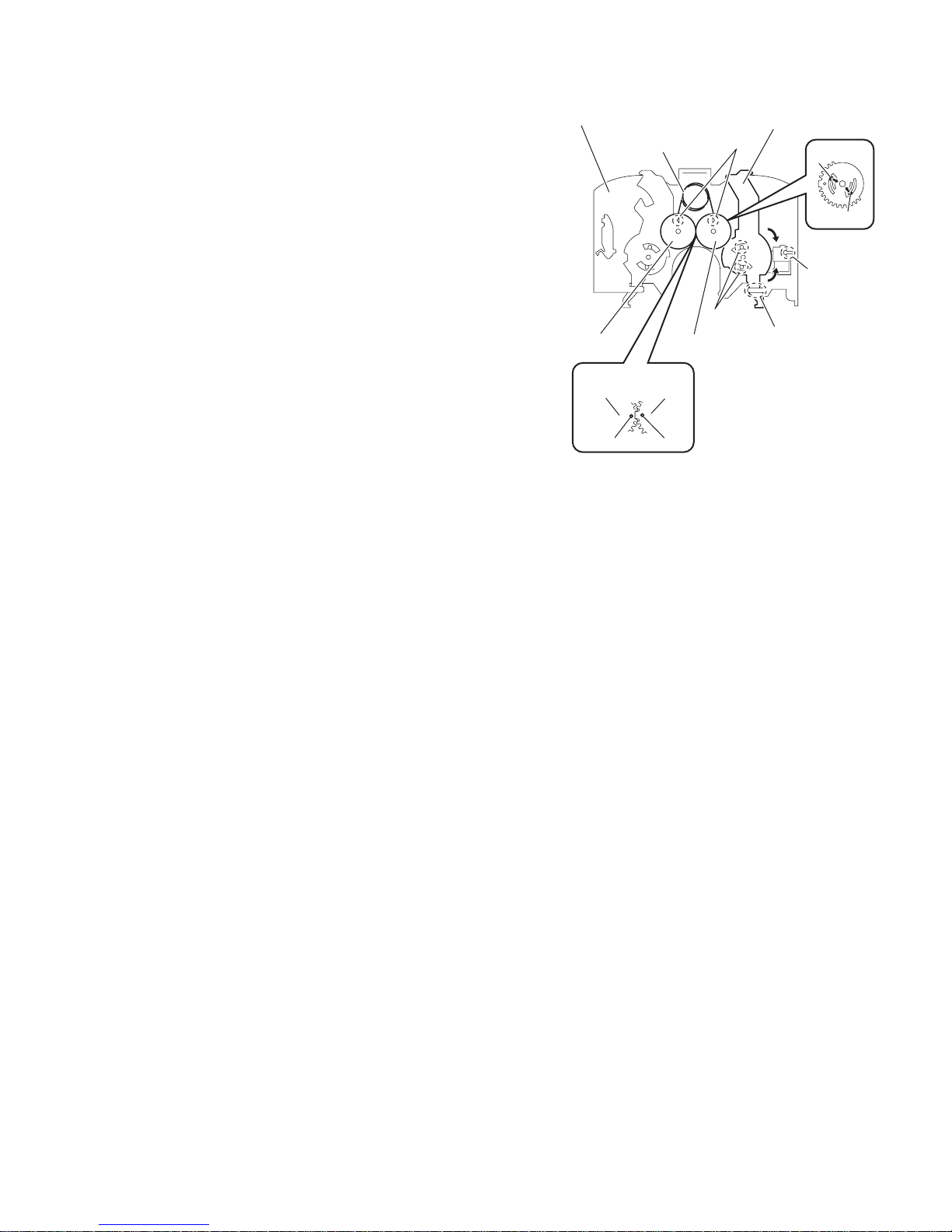
3.2.11 Removing the mode switch
(See Fig.16)
• Remove the top cover, base board, chassis unit, clamper as-
sembly, trigger arm and top plate assembly.
(1) From the top side of the top plate assembly, remove the
link gear spring from the sections x of the link gear L and
link gear R.
(2) Remove the link gear L in an upward direction whi le releas-
ing the claws y of the link gear L in the direction of the arrow.
(3) Move the mode switch in the direction of t he arrow 1 to re -
move the sections z of the top plate assembly.
(4) Move the mode switch in the direction of the arrow 2 and
remove the mode switch from the sections (aa, ab).
Note:
When reattaching the link gear L, attach it after aligning the
hole ac of the link gear L to the hole ac of the link gear R.
Reference:
When reassembling, reverse the above removing procedure.
Top plate assembly
Link gear spring
Link gear R
Link
gear R
ac ac
Link gear L
Link
gear L
aa
Fig.16
Mode switch
x
1
2
z
y
y
ab
(No.MA387<Rev.003>)1-19
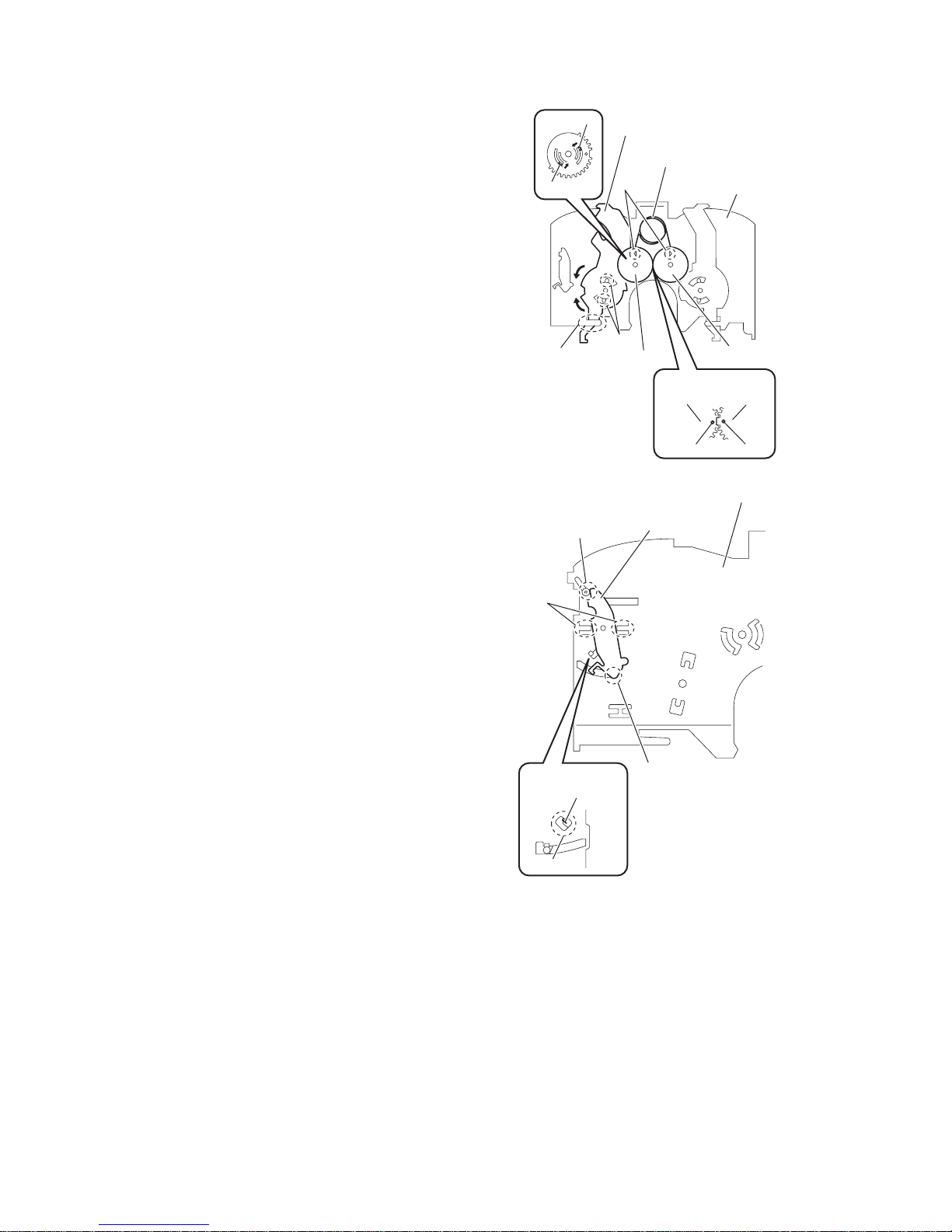
3.2.12 Removing the select arm R and select lock arm
(See Figs.17 and 18)
• Remove the top cover, base board, chassis unit, clamper as-
sembly, trigger arm and top plate asse mbly.
(1) From the top side of the top plate assembly, remove the
link gear spring from the sections ad of the link gear L and
link gear R. (See Fig.17.)
(2) Remove the link gear R in an upward direction while releas-
ing the claws ae of the lin k gear R in the dire ction of the a rrow. (See Fig.17.)
(3) Move the select arm R in the direction of the arrow 1 to re-
move the sections af of the top plate assembly. (See
Fig.17.)
(4) Move the select arm R in the direction of the arrow 2 and
remove the select arm R from the sections ag. (See
Fig.17.)
(5) From the bottom side of the top plate assembly, remove
the select lock arm spring from the section ah. (See
Fig.18.)
(6) From the top side of the top plate assembly, remove the
section aj of the select lock arm from the top plate assembly at first and remove the sections (ak, am) of th e sele ct
lock arm from the top plate assembly. (See Fig.18.)
Note:
• When removing the select lock arm spring, be careful not to
lose it. (See Fig 18.)
• When reattaching the link gear R, attach it after ali gn ing the
hole an of the link gear R to the hole an of the link gear L.
(See Fig.17.)
Reference:
When reassembling, reverse the above removing procedure.
ak
ae
1
2
af
ae
Select arm R
ad
ag
Link gear R
Select lock arm
aj
Link gear spring
Top plate assembly
Link gear L
Link
gear R
an an
Fig.17
Top plate assembly
Link
gear L
1-20 (No.MA387<Rev.003>)
Select lock
arm spring
ah
am
Fig.18
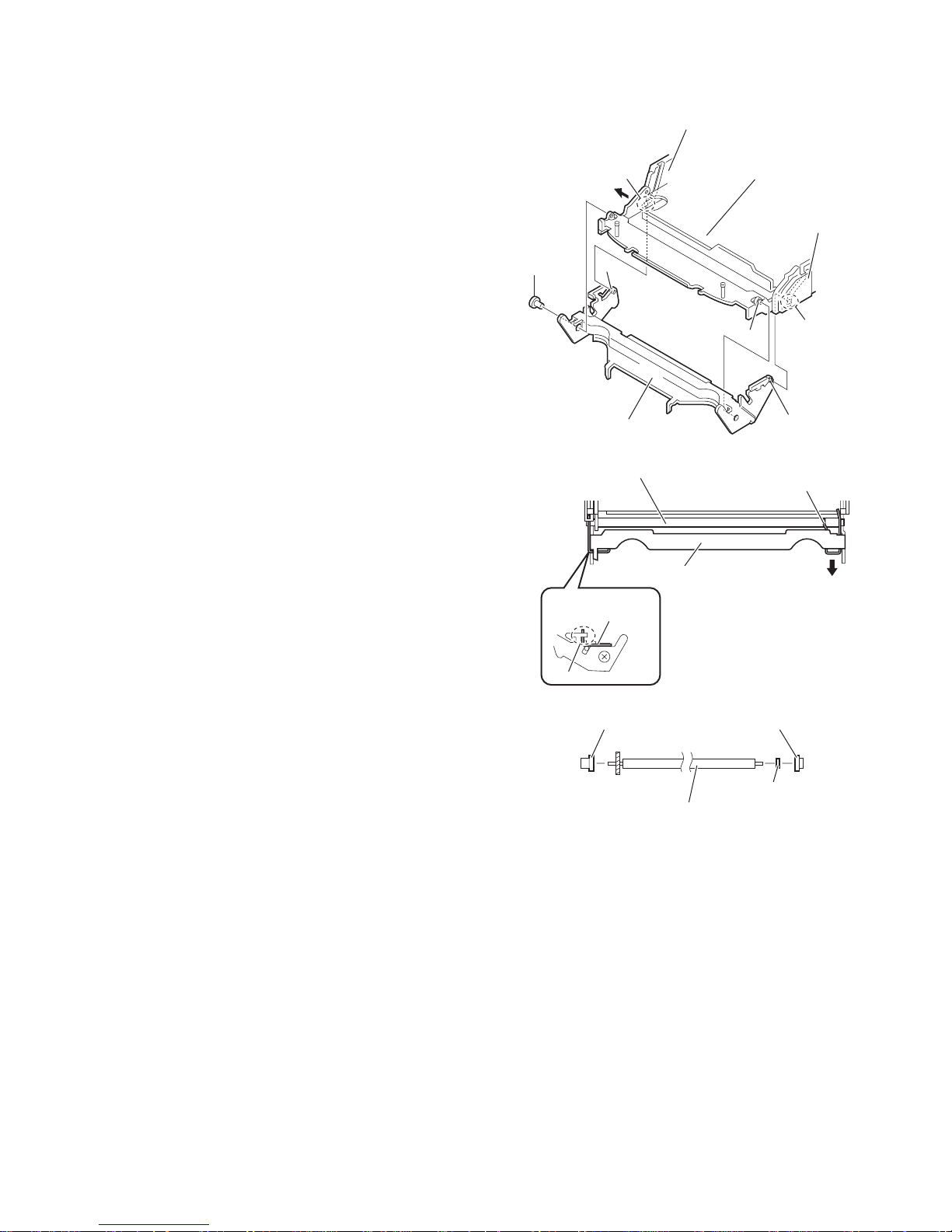
3.2.13 Removing the loading roller assembly
(See Figs.19 to 21)
• Remove the top cover, base board, chassis unit, clamper as-
sembly and top plate assembly.
(1) From the left side of the chassis unit, remove the screw J
attaching the lock arm assembly. (See Fig.19.)
(2) Remove the projection ap of the lock arm assembly from
the joint aq while opening the cam plate R in the direction
of the arrow. (See Fig.19.)
(3) Remove the lock arm assembly from the projection ar of
the chassis unit. (See Fig.19.)
(4) Remove the projection as of the lock arm assembly from
the joint at of the cam plate L assembly. (See Fig.19.)
(5) From the right side of the lock arm assembly, remove the
loading roller spring L from the section au. (See Fig.20.)
(6) From the top side of the lock arm assembly, remove the
loading roller spring R in the direction of the arrow and remove the loading roller assembly. (See Fig.20.)
(7) Remove the roller guide R, HL washer and roller guide L
from the both ends of the loading roller assembly. (See
Fig.21.)
aq
J
ap
Lock arm assembly
Loading roller assembly
Cam plate R
Fig.19
Chassis unit
Cam plate L assembly
ar
Loading roller spring R
at
as
Lock arm assembly
Loading roller
spring L
au
Fig.20
Roller guide L Roller guide R
HL washer
Loading roller assembly
Fig.21
(No.MA387<Rev.003>)1-21
 Loading...