


An Oshkosh Corporation Company
Illustrated Parts Manual
Models
G5-18A
2505H
Agrovector 25.5
S/N 0160053000 & After including
0160051045, 0160051047,
0160051049, 0160051194 &
0160051359
31200725
Revised
January 22, 2014


May 10, 2013 - A - Original Issue Of Manual
July 17, 2013 - B - Revised Manual
September 30, 2013 - C - Revised Manual
January 22, 2014 - D - Revised Manual
EFFECTIVITY PAGE
31200725 G5-18A, 2505H, 25.5 i

EFFECTIVITY PAGE
G5-18A, 2505H, 25.5 31200360ii

Machine Configuration
OY2700
1
ULTRA LOW
SULFUR DIESEL
FUEL ONLY
S < 15 mg/kg
1001125387 A
REAR VIEW OF CAB
Two configurations of each machine are included in this manual. Determine if machine is equipped with Ultra Low Sulfur Fuel Decal (1).
If equipped with the Ultra Low Sulfur decal, all specific references to this machine configuration will be referred to as Ultra Low Sulfur
(ULS) from this point forward.
If not equipped with the Ultra Low Sulfur decal, all specific references to this machine configuration will be referred to as Low Sulfur (LS)
from this point forward.
1

General Information
1. MACHINE IDENTIFICATION
Machines are identified by model & in some cases a combination of model, serial number (S/N) or regional standard (CE, AUS,
ANSI). Components may also be identified by S/N or manufacturer. Common components that may be identified by these
characteristics are attachments, engine, transmission & hydraulic components.
2. PARTS MANUAL ORGANIZATION
Product information in this manual is organized under section titles. Frame & Attaching Parts, Drive Train & Electrical are a few
examples. Each section is organized by Figure & page number. The information within the Figure is then organized by item number,
part number, description & corresponding illustration(s).
3. TABLE OF CONTENTS
A table of contents (TOC) is found toward the beginning of the manual. Figure number, description & page number are provided for
quick reference to the page containing the related information.
4. RECOMMENDED SPARE PARTS
The Recommended Spare Parts, located near the end of the manual, references most frequently used maintenance parts.
5. PART NUMBER INDEX
A numerical index listing all part numbers & the corresponding page number(s) appears at the back of the manual.
6. NON-SERVICED PARTS
In some instances it is necessary to display non-serviced parts, assemblies or installations. In the case of assemblies & installations
there will be a Ref in the Qty column & a note after the item description stating what is available for service within. In the case of
parts that are not available for service within assemblies or components there will be a NSS (Not Sold Separately) listed in the part
number column of the manual.
7. PARTS LIST ITEM NUMBERS
Numbers shown in the Item column correspond to numbers used in the associated illustration(s). Item numbers which are missing
from sequence & are not shown in the illustration(s) are not used on that page.
8. INDENTED PART DESCRIPTION
An indented part description is included in the item under which it is indented.
9. ABBREVIATIONS & SYMBOLS
AC.................................................................... Air Conditioning
ANSI ............................. American National Standards Institute
AR..........................................................................As Required
ASME.................... American Society of Mechanical Engineers
ASSY ......................................................................... Assembly
AUS..............................................................................Australia
AUX..............................................................................Auxiliary
CE............................................................European Conformity
DIA..............................................................................Diameter
EURO.........................................................................European
FT ...................................................................................... Foot
GA...................................................................................Gauge
GR ...................................................................................Grade
HD.....................................................................................Head
HYD ............................................................................Hydraulic
ID ..................................................................... Inside Diameter
IN ........................................................................................Inch
ISO............................. International Organization for Standards
ITSDF ..... Industrial Truck Standards Development Foundation
KG............................................................................... Kilogram
kW.................................................................................Kilowatt
10. ILLUSTRATION REFERENCE LETTERS
When necessary, illustrations may contain reference letters that are intended to track information from one point to another in the
illustration such as harnesses & hoses or any other information that has been separated in the illustration.
LB ....................................................................................Pound
LH.............................................................................. Left Hand
LS ............................................................................. Low Sulfur
MAX........................................................................... Maximum
MM .............................................................................Millimeter
N....................................................................................Newton
NA ...................................................................... Not Applicable
NLA ...........................................................No Longer Available
NSS ........................................................... Not Sold Separately
OD ................................................................. Outside Diameter
OZ .................................................................................. Ounce
P/N ........................................................................Part Number
QTY ..............................................................................Quantity
REF ...........................................................................Reference
REQ............................................................................ Required
RH ...........................................................................Right Hand
S/N ..................................................................... Serial Number
SAE ....................................... Society of Automotive Engineers
STD ............................................................................ Standard
ULS ..................................................................Ultra Low Sulfur
V ..........................................................................................Volt
Note: Due to continuous product improvements, JLG Industries, Inc. reserves the right to make specification changes without prior
notification. Contact JLG Industries, Inc. for updated information.
2

2
7
1
8
9
9
6
7
1
3

This Page Intentionally Left Blank
4

TABLE OF CONTENTS
FIGURE NO. TITLE PAGE NO.
SECTION 1 –
FRAME & ATTACHING PARTS . . . . . . . . . . . . . . . . . . . . . . . . . . . . . . . . . . . . . . . . . . . . . . . . 1-1
1-1 Frame & Attaching Parts . . . . . . . . . . . . . . . . . . . . . . . . . . . . . . . . . . . . . . . . . . . . . . . . . . . . . . . 1-2
1-2 Covers . . . . . . . . . . . . . . . . . . . . . . . . . . . . . . . . . . . . . . . . . . . . . . . . . . . . . . . . . . . . . . . . . . . . . 1-6
1-3 License Plate Holder Installation . . . . . . . . . . . . . . . . . . . . . . . . . . . . . . . . . . . . . . . . . . . . . . . . . 1-12
1-4 Hitches . . . . . . . . . . . . . . . . . . . . . . . . . . . . . . . . . . . . . . . . . . . . . . . . . . . . . . . . . . . . . . . . . . . . . 1-14
SECTION 2 –
BOOM . . . . . . . . . . . . . . . . . . . . . . . . . . . . . . . . . . . . . . . . . . . . . . . . . . . . . . . . . . . . . . . . . . . . 2-1
2-1 Boom Assembly - Components . . . . . . . . . . . . . . . . . . . . . . . . . . . . . . . . . . . . . . . . . . . . . . . . . . 2-2
2-2 Boom Assembly - Pads & Shims . . . . . . . . . . . . . . . . . . . . . . . . . . . . . . . . . . . . . . . . . . . . . . . . . 2-6
2-3 Quick Coupler . . . . . . . . . . . . . . . . . . . . . . . . . . . . . . . . . . . . . . . . . . . . . . . . . . . . . . . . . . . . . . . . 2-8
2-4 Universal Quick Coupler . . . . . . . . . . . . . . . . . . . . . . . . . . . . . . . . . . . . . . . . . . . . . . . . . . . . . . . . 2-10
SECTION 3 –
ATTACHMENTS . . . . . . . . . . . . . . . . . . . . . . . . . . . . . . . . . . . . . . . . . . . . . . . . . . . . . . . . . . . . 3-1
3-1 Standard Carriage . . . . . . . . . . . . . . . . . . . . . . . . . . . . . . . . . . . . . . . . . . . . . . . . . . . . . . . . . . . . 3-2
3-2 Universal Standard Carriage . . . . . . . . . . . . . . . . . . . . . . . . . . . . . . . . . . . . . . . . . . . . . . . . . . . . 3-4
3-3 Side Tilt Carriage . . . . . . . . . . . . . . . . . . . . . . . . . . . . . . . . . . . . . . . . . . . . . . . . . . . . . . . . . . . . . 3-6
3-4 Universal Side Tilt Carriage . . . . . . . . . . . . . . . . . . . . . . . . . . . . . . . . . . . . . . . . . . . . . . . . . . . . . 3-8
3-5 Universal Side Shift Carriage . . . . . . . . . . . . . . . . . . . . . . . . . . . . . . . . . . . . . . . . . . . . . . . . . . . . 3-10
3-6 Forks . . . . . . . . . . . . . . . . . . . . . . . . . . . . . . . . . . . . . . . . . . . . . . . . . . . . . . . . . . . . . . . . . . . . . . 3-12
3-7 Grapple Bucket . . . . . . . . . . . . . . . . . . . . . . . . . . . . . . . . . . . . . . . . . . . . . . . . . . . . . . . . . . . . . . . 3-14
3-8 Light Material Buckets . . . . . . . . . . . . . . . . . . . . . . . . . . . . . . . . . . . . . . . . . . . . . . . . . . . . . . . . . 3-18
3-9 Fork Mounted Hook . . . . . . . . . . . . . . . . . . . . . . . . . . . . . . . . . . . . . . . . . . . . . . . . . . . . . . . . . . . 3-20
3-10 Universal Hitch Attachment . . . . . . . . . . . . . . . . . . . . . . . . . . . . . . . . . . . . . . . . . . . . . . . . . . . . . 3-24
SECTION 4 –
ENGINE & ATTACHING PARTS . . . . . . . . . . . . . . . . . . . . . . . . . . . . . . . . . . . . . . . . . . . . . . . 4-1
4-1 Engine Installation . . . . . . . . . . . . . . . . . . . . . . . . . . . . . . . . . . . . . . . . . . . . . . . . . . . . . . . . . . . . 4-2
4-2 Fuel Tank & Lines . . . . . . . . . . . . . . . . . . . . . . . . . . . . . . . . . . . . . . . . . . . . . . . . . . . . . . . . . . . . 4-6
4-3 Radiator Installation . . . . . . . . . . . . . . . . . . . . . . . . . . . . . . . . . . . . . . . . . . . . . . . . . . . . . . . . . . . 4-8
4-4 Air Cleaner Installation . . . . . . . . . . . . . . . . . . . . . . . . . . . . . . . . . . . . . . . . . . . . . . . . . . . . . . . . . 4-12
4-5 Exhaust Installation . . . . . . . . . . . . . . . . . . . . . . . . . . . . . . . . . . . . . . . . . . . . . . . . . . . . . . . . . . . 4-14
4-6 Engine Heater Installation . . . . . . . . . . . . . . . . . . . . . . . . . . . . . . . . . . . . . . . . . . . . . . . . . . . . . . 4-18
4-7 Lubricity Doser Installation . . . . . . . . . . . . . . . . . . . . . . . . . . . . . . . . . . . . . . . . . . . . . . . . . . . . . . 4-20
SECTION 5 –
DRIVE TRAIN . . . . . . . . . . . . . . . . . . . . . . . . . . . . . . . . . . . . . . . . . . . . . . . . . . . . . . . . . . . . . . 5-1
5-1 Drive Train Installation . . . . . . . . . . . . . . . . . . . . . . . . . . . . . . . . . . . . . . . . . . . . . . . . . . . . . . . . . 5-2
5-2 Front Axle Assembly . . . . . . . . . . . . . . . . . . . . . . . . . . . . . . . . . . . . . . . . . . . . . . . . . . . . . . . . . . 5-4
5-3 Central Housing & Steering . . . . . . . . . . . . . . . . . . . . . . . . . . . . . . . . . . . . . . . . . . . . . . . . . . . . . 5-6
5-4 Differential . . . . . . . . . . . . . . . . . . . . . . . . . . . . . . . . . . . . . . . . . . . . . . . . . . . . . . . . . . . . . . . . . . 5-8
5-5 Hub Reduction . . . . . . . . . . . . . . . . . . . . . . . . . . . . . . . . . . . . . . . . . . . . . . . . . . . . . . . . . . . . . . . 5-12
31200725 G5-18A, 2505H, 25.5 5

TABLE OF CONTENTS
FIGURE NO. TITLE PAGE NO.
5-6 Brakes . . . . . . . . . . . . . . . . . . . . . . . . . . . . . . . . . . . . . . . . . . . . . . . . . . . . . . . . . . . . . . . . . . . . . 5-14
5-7 Rear Axle Assembly . . . . . . . . . . . . . . . . . . . . . . . . . . . . . . . . . . . . . . . . . . . . . . . . . . . . . . . . . . . 5-16
5-8 Central Housing & Steering . . . . . . . . . . . . . . . . . . . . . . . . . . . . . . . . . . . . . . . . . . . . . . . . . . . . . 5-18
5-9 Differential . . . . . . . . . . . . . . . . . . . . . . . . . . . . . . . . . . . . . . . . . . . . . . . . . . . . . . . . . . . . . . . . . . 5-20
5-10 Hub Reduction . . . . . . . . . . . . . . . . . . . . . . . . . . . . . . . . . . . . . . . . . . . . . . . . . . . . . . . . . . . . . . . 5-22
5-11 Fender Installation . . . . . . . . . . . . . . . . . . . . . . . . . . . . . . . . . . . . . . . . . . . . . . . . . . . . . . . . . . . . 5-24
5-12 Tires & Rims . . . . . . . . . . . . . . . . . . . . . . . . . . . . . . . . . . . . . . . . . . . . . . . . . . . . . . . . . . . . . . . . . 5-26
SECTION 6 –
CAB . . . . . . . . . . . . . . . . . . . . . . . . . . . . . . . . . . . . . . . . . . . . . . . . . . . . . . . . . . . . . . . . . . . . . . 6-1
6-1 Cab Installation . . . . . . . . . . . . . . . . . . . . . . . . . . . . . . . . . . . . . . . . . . . . . . . . . . . . . . . . . . . . . . 6-2
6-2 Open Cab . . . . . . . . . . . . . . . . . . . . . . . . . . . . . . . . . . . . . . . . . . . . . . . . . . . . . . . . . . . . . . . . . . . 6-6
6-3 Enclosed Cab Installation . . . . . . . . . . . . . . . . . . . . . . . . . . . . . . . . . . . . . . . . . . . . . . . . . . . . . . . 6-8
6-4 Cab Interior . . . . . . . . . . . . . . . . . . . . . . . . . . . . . . . . . . . . . . . . . . . . . . . . . . . . . . . . . . . . . . . . . 6-12
6-5 Overhead Console Installation . . . . . . . . . . . . . . . . . . . . . . . . . . . . . . . . . . . . . . . . . . . . . . . . . . . 6-14
6-6 Suspension Seat . . . . . . . . . . . . . . . . . . . . . . . . . . . . . . . . . . . . . . . . . . . . . . . . . . . . . . . . . . . . . 6-16
6-7 Wiper Installation . . . . . . . . . . . . . . . . . . . . . . . . . . . . . . . . . . . . . . . . . . . . . . . . . . . . . . . . . . . . . 6-18
6-8 Heater & AC . . . . . . . . . . . . . . . . . . . . . . . . . . . . . . . . . . . . . . . . . . . . . . . . . . . . . . . . . . . . . . . . . 6-20
6-9 AC Condenser Installation . . . . . . . . . . . . . . . . . . . . . . . . . . . . . . . . . . . . . . . . . . . . . . . . . . . . . . 6-24
6-10 AC System Installation . . . . . . . . . . . . . . . . . . . . . . . . . . . . . . . . . . . . . . . . . . . . . . . . . . . . . . . . . 6-26
SECTION 7 –
CONTROLS . . . . . . . . . . . . . . . . . . . . . . . . . . . . . . . . . . . . . . . . . . . . . . . . . . . . . . . . . . . . . . . . 7-1
7-1 Brake . . . . . . . . . . . . . . . . . . . . . . . . . . . . . . . . . . . . . . . . . . . . . . . . . . . . . . . . . . . . . . . . . . . . . . 7-2
7-2 Accelerator . . . . . . . . . . . . . . . . . . . . . . . . . . . . . . . . . . . . . . . . . . . . . . . . . . . . . . . . . . . . . . . . . . 7-4
7-3 Steering Column . . . . . . . . . . . . . . . . . . . . . . . . . . . . . . . . . . . . . . . . . . . . . . . . . . . . . . . . . . . . . 7-6
7-4 Boom Joystick . . . . . . . . . . . . . . . . . . . . . . . . . . . . . . . . . . . . . . . . . . . . . . . . . . . . . . . . . . . . . . . 7-8
SECTION 8 –
HYDRAULIC CIRCUITS . . . . . . . . . . . . . . . . . . . . . . . . . . . . . . . . . . . . . . . . . . . . . . . . . . . . . . .8-1
8-1 Supply Circuit . . . . . . . . . . . . . . . . . . . . . . . . . . . . . . . . . . . . . . . . . . . . . . . . . . . . . . . . . . . . . . . . 8-2
8-2 Dump Circuit . . . . . . . . . . . . . . . . . . . . . . . . . . . . . . . . . . . . . . . . . . . . . . . . . . . . . . . . . . . . . . . . 8-6
8-3 Steer Select . . . . . . . . . . . . . . . . . . . . . . . . . . . . . . . . . . . . . . . . . . . . . . . . . . . . . . . . . . . . . . . . . 8-10
8-4 Service/Park Brake . . . . . . . . . . . . . . . . . . . . . . . . . . . . . . . . . . . . . . . . . . . . . . . . . . . . . . . . . . . 8-12
8-5 Boom Joystick . . . . . . . . . . . . . . . . . . . . . . . . . . . . . . . . . . . . . . . . . . . . . . . . . . . . . . . . . . . . . . . 8-14
8-6 Lift Cylinder . . . . . . . . . . . . . . . . . . . . . . . . . . . . . . . . . . . . . . . . . . . . . . . . . . . . . . . . . . . . . . . . . 8-18
8-7 Extend/Retract Cylinder . . . . . . . . . . . . . . . . . . . . . . . . . . . . . . . . . . . . . . . . . . . . . . . . . . . . . . . . 8-22
8-8 Tilt & Compensating . . . . . . . . . . . . . . . . . . . . . . . . . . . . . . . . . . . . . . . . . . . . . . . . . . . . . . . . . . . 8-24
8-9 Auxiliary Hydraulics . . . . . . . . . . . . . . . . . . . . . . . . . . . . . . . . . . . . . . . . . . . . . . . . . . . . . . . . . . . 8-26
8-10 Rear Auxiliary Hydraulics . . . . . . . . . . . . . . . . . . . . . . . . . . . . . . . . . . . . . . . . . . . . . . . . . . . . . . . 8-28
8-11 Auxiliary Hydraulics Pressure Relief . . . . . . . . . . . . . . . . . . . . . . . . . . . . . . . . . . . . . . . . . . . . . . 8-30
G5-18A, 2505H, 25.5 312007256

TABLE OF CONTENTS
FIGURE NO. TITLE PAGE NO.
SECTION 9 –
HYDRAULIC COMPONENTS . . . . . . . . . . . . . . . . . . . . . . . . . . . . . . . . . . . . . . . . . . . . . . . . . . 9-1
9-1 Lift Cylinder . . . . . . . . . . . . . . . . . . . . . . . . . . . . . . . . . . . . . . . . . . . . . . . . . . . . . . . . . . . . . . . . . 9-2
9-2 Extend/Retract Cylinder . . . . . . . . . . . . . . . . . . . . . . . . . . . . . . . . . . . . . . . . . . . . . . . . . . . . . . . . 9-6
9-3 Tilt Cylinder . . . . . . . . . . . . . . . . . . . . . . . . . . . . . . . . . . . . . . . . . . . . . . . . . . . . . . . . . . . . . . . . . 9-8
9-4 Compensating Cylinder . . . . . . . . . . . . . . . . . . . . . . . . . . . . . . . . . . . . . . . . . . . . . . . . . . . . . . . . 9-10
9-5 Fork Locking Cylinder . . . . . . . . . . . . . . . . . . . . . . . . . . . . . . . . . . . . . . . . . . . . . . . . . . . . . . . . . . 9-12
9-6 Side Tilt Carriage Cylinder & Grapple Bucket Cylinder . . . . . . . . . . . . . . . . . . . . . . . . . . . . . . . . 9-14
9-7 Universal Side Shift Cylinder . . . . . . . . . . . . . . . . . . . . . . . . . . . . . . . . . . . . . . . . . . . . . . . . . . . . 9-16
9-8 Main Control Valve . . . . . . . . . . . . . . . . . . . . . . . . . . . . . . . . . . . . . . . . . . . . . . . . . . . . . . . . . . . . 9-18
9-9 Front Drive Motor . . . . . . . . . . . . . . . . . . . . . . . . . . . . . . . . . . . . . . . . . . . . . . . . . . . . . . . . . . . . . 9-20
9-10 Hydrostatic Drive Pump . . . . . . . . . . . . . . . . . . . . . . . . . . . . . . . . . . . . . . . . . . . . . . . . . . . . . . . . 9-22
9-11 Gear Pump . . . . . . . . . . . . . . . . . . . . . . . . . . . . . . . . . . . . . . . . . . . . . . . . . . . . . . . . . . . . . . . . . . 9-24
9-12 Divertor Valve . . . . . . . . . . . . . . . . . . . . . . . . . . . . . . . . . . . . . . . . . . . . . . . . . . . . . . . . . . . . . . . . 9-26
9-13 Steering Select Valve . . . . . . . . . . . . . . . . . . . . . . . . . . . . . . . . . . . . . . . . . . . . . . . . . . . . . . . . . . 9-28
9-14 Pilot Select Valve . . . . . . . . . . . . . . . . . . . . . . . . . . . . . . . . . . . . . . . . . . . . . . . . . . . . . . . . . . . . . 9-30
9-15 Brake Valves . . . . . . . . . . . . . . . . . . . . . . . . . . . . . . . . . . . . . . . . . . . . . . . . . . . . . . . . . . . . . . . . 9-32
SECTION 10 –
ELECTRICAL . . . . . . . . . . . . . . . . . . . . . . . . . . . . . . . . . . . . . . . . . . . . . . . . . . . . . . . . . . . . . . 10-1
10-1 Engine Compartment Electrical Installation . . . . . . . . . . . . . . . . . . . . . . . . . . . . . . . . . . . . . . . . . 10-2
10-2 Boom and Frame Electrical Installation . . . . . . . . . . . . . . . . . . . . . . . . . . . . . . . . . . . . . . . . . . . . 10-4
10-3 Cab Electrical Installation . . . . . . . . . . . . . . . . . . . . . . . . . . . . . . . . . . . . . . . . . . . . . . . . . . . . . . . 10-8
10-4 Cab Switches . . . . . . . . . . . . . . . . . . . . . . . . . . . . . . . . . . . . . . . . . . . . . . . . . . . . . . . . . . . . . . . . 10-10
10-5 Work Lights . . . . . . . . . . . . . . . . . . . . . . . . . . . . . . . . . . . . . . . . . . . . . . . . . . . . . . . . . . . . . . . . . 10-12
10-6 Drive Lights . . . . . . . . . . . . . . . . . . . . . . . . . . . . . . . . . . . . . . . . . . . . . . . . . . . . . . . . . . . . . . . . . 10-16
10-7 Engine Harness . . . . . . . . . . . . . . . . . . . . . . . . . . . . . . . . . . . . . . . . . . . . . . . . . . . . . . . . . . . . . . 10-18
10-8 Frame Harness . . . . . . . . . . . . . . . . . . . . . . . . . . . . . . . . . . . . . . . . . . . . . . . . . . . . . . . . . . . . . . . 10-22
10-9 Frame Option Harness . . . . . . . . . . . . . . . . . . . . . . . . . . . . . . . . . . . . . . . . . . . . . . . . . . . . . . . . . 10-28
10-10 Cab Harness . . . . . . . . . . . . . . . . . . . . . . . . . . . . . . . . . . . . . . . . . . . . . . . . . . . . . . . . . . . . . . . . 10-34
10-11 Cab Roof Harness . . . . . . . . . . . . . . . . . . . . . . . . . . . . . . . . . . . . . . . . . . . . . . . . . . . . . . . . . . . . 10-40
10-12 Roof Worklight Harness . . . . . . . . . . . . . . . . . . . . . . . . . . . . . . . . . . . . . . . . . . . . . . . . . . . . . . . . 10-42
10-13 Boom Worklight Harness . . . . . . . . . . . . . . . . . . . . . . . . . . . . . . . . . . . . . . . . . . . . . . . . . . . . . . . 10-44
10-14 Beacon Worklight Harness . . . . . . . . . . . . . . . . . . . . . . . . . . . . . . . . . . . . . . . . . . . . . . . . . . . . . . 10-46
10-15 Boom Aux Harness . . . . . . . . . . . . . . . . . . . . . . . . . . . . . . . . . . . . . . . . . . . . . . . . . . . . . . . . . . . 10-48
10-16 LSI Boom Sensor Harness . . . . . . . . . . . . . . . . . . . . . . . . . . . . . . . . . . . . . . . . . . . . . . . . . . . . . . 10-50
10-17 Ignition Switch Jumper Harness . . . . . . . . . . . . . . . . . . . . . . . . . . . . . . . . . . . . . . . . . . . . . . . . . . 10-52
10-18 Mode Select Harness . . . . . . . . . . . . . . . . . . . . . . . . . . . . . . . . . . . . . . . . . . . . . . . . . . . . . . . . . . 10-54
10-19 Heater Jumper Harness . . . . . . . . . . . . . . . . . . . . . . . . . . . . . . . . . . . . . . . . . . . . . . . . . . . . . . . . 10-56
SECTION 11 –
DECALS . . . . . . . . . . . . . . . . . . . . . . . . . . . . . . . . . . . . . . . . . . . . . . . . . . . . . . . . . . . . . . . . . . 11-1
11-1 Cab & Frame Decals . . . . . . . . . . . . . . . . . . . . . . . . . . . . . . . . . . . . . . . . . . . . . . . . . . . . . . . . . . 11-2
11-2 Boom Decals . . . . . . . . . . . . . . . . . . . . . . . . . . . . . . . . . . . . . . . . . . . . . . . . . . . . . . . . . . . . . . . . 11-8
31200725 G5-18A, 2505H, 25.5 7

TABLE OF CONTENTS
FIGURE NO. TITLE PAGE NO.
SECTION 12 –
RECOMMENDED SPARE PARTS . . . . . . . . . . . . . . . . . . . . . . . . . . . . . . . . . . . . . . . . . . . . . . 12-1
SECTION 13 – PART NUMBER INDEX . . . . . . . . . . . . . . . . . . . . . . . . . . . . . . . . . . . . . . . . . . . . . 13-1
G5-18A, 2505H, 25.5 312007258

SECTION 1
FRAME & ATTACHING PARTS
31200725 G5-18A, 2505H, 25.5

FRAME & ATTACHING PARTS
1
8
3
4
5
5
6
7
2
9
10
11
12
12
13
13
14
15
16
14
17
18
19
20
21
21
23
24
25
101
102
104
105
106
106
107
108
109
109
109
112
113
113
113
113
113
109
113
113
114
116
117
118
119
121
124
125
301
302
303
304
401
402
403
501
201
113
202
203
601
602
603
605
604
702
701
702
701
703
704
751
752
753
PY8860
VIEW OF REAR PLATE
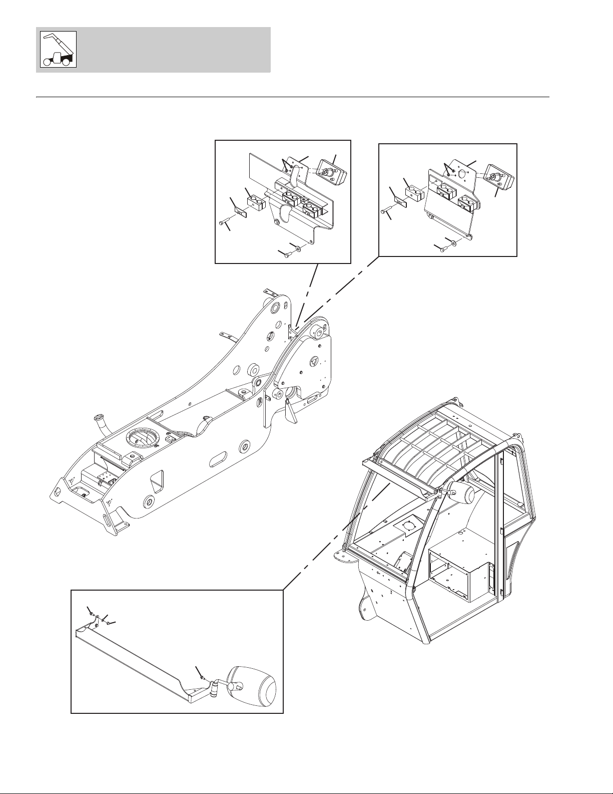
Figure 1-1 Frame & Attaching Parts
G5-18A, 2505H, 25.5 312007251-2

FRAME & ATTACHING PARTS
Figure 1-1 Frame & Attaching Parts
Item Part Number Qty. Description Rev.
1001137271 Ref FRAME INSTALLATION, (not available to order, see items 1 thru 25 for service) B
1 1001151133 2 HEAVY HEX NUT, 3/4-10
2 0641506 2 HEX HD CAPSCREW, 5/16-18X3/4, GR5
3 0641514 3 HEX HD CAPSCREW, 5/16-18X1-3/4, GR5
4 1001151086 4 HEX HD CAPSCREW, 3/4-10X2-1/2, GR8
5 3272201 2 HEX NUT, 3/4-10, GR8, (torque to 135-105 lb-ft/183-142 Nm)
6 3311505 3 LOCKNUT, 5/16-18
7 3931416 2 SOCKET HD CAPSCREW, 1/4-20X1
8 4711500 2 WASHER, 5/16
9 4712200 1 WASHER, 3/4
10 1001151132 4 WASHER, 3/4
11 4762200 1 LOCKWASHER, 3/4
12 4891500 6 WASHER, 5/16
13 83483497 2 GEAR CLAMP
14 86883327 2 HOSE CLAMP
15 1001148483 1 VENT HOSE
16 1001080086 1 FILL HOSE
17 1001080171 1 REAR HITCH MOUNT PLATE
18 1001080573 1 FUEL NOZZLE TUBE
19 1001144474 1 MIRROR BRACKET
1001158104 1 OFFSET MIRROR BRACKET, (for homologation machines)
20 1001081185 1 BOOM STOP PAD
21 1001142680 103 in SPLIT POLY CONDUIT
23 1001081364 2 RUBBER GROMMET
24 1001133822 1 HEADLIGHT BRACKET
25 1001148177 1 RECTANGULAR MIRROR
101 1001157307 1 ELECTRIC COMPONENTS MOUNT
102 0641403 2 HEX HD CAPSCREW, 1/4-20X3/8, GR5
104 0641624 1 HEX HD CAPSCREW, 3/8-16X3, GR5
105 0641836 1 HEX HD CAPSCREW, 1/2-13X4-1/2, GR5
106 0641852 2 HEX HD CAPSCREW, 1/2-13X6-1/2, GR5
107 2220239 2 ADAPTER, PLUG
108 3271601 1 HEX NUT, 3/8-16
109 3271801 4 HEX NUT, 1/2-13
112 4751600 1 WASHER, 3/8
113 90027471 8 WASHER, 1/2
114 91563136 1 OIL LEVEL INDICATOR, (torque to mounting bolts to 6 lb-ft/8 Nm)
116 1001080944 1 MECHANICAL ADAPTER, PLUG
117 1001145882 1 LOCKABLE HYDRAULIC FILLER CAP
118 1001081363 2 MAGNET
119 1001130291 1 COUNTERWEIGHT PLATE
121 NSS 1 FRAME WELDMENT
124 1001130289K 1 WEIGHT ASSY
125 0641856 1 HEX HD CAPSCREW, 1/2-13X7
1001080571 1 DIESEL FUEL CAP INSTALLATION, (includes items 201 thru 203) B
201 1001001422 1 FILLER NECK TANK ADAPTER
202 1001080707 1 DIESEL FUEL LOCKING CAP
203 0100093 AR
LOCTITE
®
30512
™
31200725 G5-18A, 2505H, 25.5 1-3

FRAME & ATTACHING PARTS
Figure 1-1 Frame & Attaching Parts (Continued)
Item Part Number Qty. Description Rev.
0275778 1 LIFT CYLINDER LOCK INSTALLATION, (includes items 301 thru 305) C
301 909304 AR RUBBER PROFILE, 18X5mm
302 1271599 1 LIFT CYLINDER LOCK WELDMENT
303 1784861 2 O-RING
304 1001099887 2 HANDLE SCREW, 12X103mm
305 Ref CYLINDER LOCK WARNING DECAL, (not shown),
(see Figure 11-1 for details)
1001081106 Ref COUNTERWEIGHT INSTALLATION, (ANSI),
(not available to order, see items 401 thru 403 for service)
1001081107 Ref COUNTERWEIGHT INSTALLATION, (CE),
(not available to order, see items 401 thru 403 for service)
1001137138 Ref COUNTERWEIGHT INSTALLATION, (AUS),
(not available to order, see items 401 thru 501 for service)
401 0682220 4 HEX HD CAPSCREW, 3/4-10X2-1/2, GR8
402 4752200 4 WASHER, 3/4
403 1001080861 1 COUNTERWEIGHT, 460 LB/209 KG, (ANSI)
1001081105 1 COUNTERWEIGHT, 129 KG/284 LB, (CE)
1001137099 1 COUNTERWEIGHT, 32.6 KG/720 LB, (AUS)
501 0100071 AR
1
0275779 Ref WHEEL CHOCK INSTALLATION, (not available to order, see items 601 thru 605
601 806253 1 WEDGE ASSY
602 4811900 4 WASHER, 8mm
603 0760806 4 HEX HD CAPSCREW, 8X12mm
604 1060628 1 TIE DOWN CABLE
605 806264 1 WEDGE HOLDER
1001104784 Ref CONVEX MIRROR INSTALLATION, (not available to order, see items 701 thru
701 4712200 2 WASHER, 3/4
702 88501012 2 HEX NUT, 3/4-10
703 1001008436 1 MIRROR ASSY, (includes items 751 thru 753) B
704 1001080241 1 REAR MOUNT MIRROR BAR
751 1001008475 2 LOCKWASHER, #12
752 1001009062 2 WASHER
753 1001010838 2 HEX HD BOLT
LOCTITE
for service)
704 for service)
®
262™, (AUS)
B
B
A
C
A
G5-18A, 2505H, 25.5 312007251-4

FRAME & ATTACHING PARTS
Figure 1-1 Frame & Attaching Parts (Continued)
Item Part Number Qty. Description Rev.
31200725 G5-18A, 2505H, 25.5 1-5

FRAME & ATTACHING PARTS
Figure 1-2 Covers
G5-18A, 2505H, 25.5 312007251-6

FRAME & ATTACHING PARTS
201
214
211
226
214
202
214
211
201
201
201
214
214
211
214
229
230
231
202
214
211
214
202
214
211
214
214
211
214
211
214
323
315
311
303
202
403
402
401
405
405
404
PY8880
Figure 1-2 Covers (Continued)
31200725 G5-18A, 2505H, 25.5 1-7

FRAME & ATTACHING PARTS
508
509
510
507
506
501
502
604
603
601
605
606
P 9290Y
509
511
2505H & 25.5
Figure 1-2 Covers (Continued)
G5-18A, 2505H, 25.5 312007251-8

FRAME & ATTACHING PARTS
Figure 1-2 Covers
Item Part Number Qty. Description Rev.
1001142092 Ref HOOD INSTALLATION, (G5-18A), (not available to order, see items 1 thru 33 for
service)
1001142095 Ref HOOD INSTALLATION, (2505H), (not available to order, see items 1 thru 33,
127, 128 & 133 for service)
1001142097 Ref HOOD INSTALLATION, (25.5), (not available to order, see items 1 thru 33, 127,
128 & 133 for service)
1 0641505 4 HEX HD CAPSCREW, 5/16-18X5/8, GR5
2 0641509 4 HEX HD CAPSCREW, 5/16-18X1-1/8, GR5
3 0641516 1 HEX HD CAPSCREW, 5/16-18X2, GR5
4 0641608 21 HEX HD CAPSCREW, 3/8-16X1, GR5
5 0641612 8 HEX HD CAPSCREW, 3/8-16X1-1/2, GR5
6 0791404 2 SCREW, 1/4-20X1/2
7 0791607 4 SCREW, 3/8-16X7/8
8 3271501 7 HEX NUT, 5/16-18
9 1001148294 2 GAS SPRING, (G5-18A)
4160139 2 GAS SPRING, (2505H)
10 4711500 16 WASHER, 5/16
11 4711600 37 WASHER, 3/8
12 4751600 2 WASHER, 3/8
13 88501006 2 HEX NUT, 3/8-16
14 1001081299K 1 FUEL FILTER ACCESS PANEL
15 1001097160 78 in SELF-GRIPPING BULB SEAL
16 1001149135 1 LATCH CATCH BRACKET
17 1001141534 1 SIDE SKIRT PANEL
18 1001142265 1 HOOD HINGE MOUNT WELDMENT PLATE
19 1001142266 1 REAR FENDER WELDMENT PANEL
20 1001142267 1 FRONT FENDER WELDMENT PANEL
21 1001142354 1 GAS SPRING WELDMENT MOUNT
22 1001142393 1 HOOD ASSY, (G5-18A), (includes items 501 thru 511) D
1001149482 1 HOOD ASSY, (2505H), (includes items 501 thru 606) B
1001149485 1 HOOD ASSY, (25.5), (includes items 501 thru 606) B
23 1001143142 2 HOOD HINGE
25 1001143391 1 AIR INTAKE SEAL
26 1001143997 1 LATCH CATCH MOUNT
27 1001144369 1 FOAM GASKET SEAL
28 1001149810 1 BELLY PAN PLATE
29 1001149811 1 BELLY PAN WELDMENT PLATE
30 1001090344 52 in NEOPRENE TAPE, 1/16X1/2
31 1001156315 1 COVER PLATE
32 0641605 4 HEX HD CAPSCREW, 3/8-16X5/8
33 3271601 4 HEX NUT, 3/8-16, GR8
127 1001144990 1 SOUND INSULATE, BELLY PAN, (2505H & 25.5)
128 1001144991 1 SOUND INSULATE, REAR FENDER, (2505H & 25.5)
133 1001151983 1 SOUND INSULATE, FIREWALL, (2505H & 25.5)
201 0681516 5 HEX HD CAPSCREW, 5/16-18X2, GR8
202 0681518 8 HEX HD CAPSCREW, 5/16-18X2-1/4, GR8
211 3271501 13 HEX NUT, 5/16-18
214 4711500 26 WASHER, 5/16
226 1001156243 1 COOLANT TANK PLATE
E
C
C
31200725 G5-18A, 2505H, 25.5 1-9

FRAME & ATTACHING PARTS
Figure 1-2 Covers (Continued)
Item Part Number Qty. Description Rev.
229 Ref FILTER BRACKET, (see Figure 4-2 for details)
230 1001143879 1 COOLER FRONT SUPPORT
231 1001143880 1 COOLER REAR SUPPORT
303 0641406 12 HEX HD CAPSCREW, 1/4-20X3/4, GR5
311 4711400 12 WASHER, 1/4
315 1001080092 1 HYDRAULIC ACCESS COVER GASKET
323 1001080091K 1 HYDRAULIC TANK ACCESS COVER
1001140270 Ref BATTERY COVER INSTALLATION, (not available to order, see items 401 thru
405 for service)
401 1001080644 1 CAM LATCH
402 1001081000 1 CAM LOCK LATCH
403 1001140269 1 BATTERY COVER
404 1001130220 2 TINNERMAN NUT, M6
405 1001151183 2 THUMB SCREW, M6-1X25.4
501 3290605 4 HEX LOCKNUT, M6X1
502 4811700 4 WASHER, 6mm
503 1001122219 1 COMPRESSION LATCH
504 1001142116 1 HOOD, (G5-18A & 2505H)
1001142116SD 1 HOOD, (25.5)
506 1001143389 1 AIR INTAKE CHANNEL
507 1001143422 1 HINGE & GAS SPRING MOUNT
508 1001143632 1 COOLER VENT
509 1001097159 83 in SELF-GRIPPING BULB SEAL
510 1001144364 1 AIR DAM SEAL
®
511 0100090 AR
LOCTITE
454
™
601 1001081328 19 FASTENER, (2505H & 25.5)
603 1001144993 1 SOUND INSULATE, (2505H & 25.5)
604 1001144995 1 SOUND INSULATE, (2505H & 25.5)
605 1001149493 19 CAP, (2505H & 25.5)
606 1001149495 19 WASHER, (2505H & 25.5)
B
G5-18A, 2505H, 25.5 312007251-10

FRAME & ATTACHING PARTS
Figure 1-2 Covers (Continued)
Item Part Number Qty. Description Rev.
31200725 G5-18A, 2505H, 25.5 1-11
FRAME & ATTACHING PARTS
104
102
103
104
9
10
6
7
8
11
9
10
6
8
7
PAL5062
212
204
11
212
204
CE & AUS - IF EQUIPPED
ANSI
CE & AUS - IF EQUIPPED
Figure 1-3 License Plate Holder Installation
G5-18A, 2505H, 25.5 312007251-12

FRAME & ATTACHING PARTS
Figure 1-3 License Plate Holder Installation
Item Part Number Qty. Description Rev.
1001081394 Ref REAR LICENSE PLATE HOLDER INSTALLATION, (CE & AUS - if equipped),
(not available for service, see items 6 thru 11 for service)
1001081422 Ref REAR LICENSE PLATE HOLDER INSTALLATION, (ANSI),
(CE & AUS - if equipped), (not available for service, see items 6 thru 11 for
service)
6 0641516 3 HEX HD CAPSCREW, 5/16-18X2, GR5
7 0641607 2 HEX HD CAPSCREW, 3/8-16X7/8
8 4751600 2 WASHER, 3/8
9 77133137 3 COVER PLATE
10 77323029 3 CLAMP SET
11 1001081425 1 LICENSE BRACKET, (CE & AUS - if equipped)
1001097684 1 LICENSE BRACKET HOSE CLAMP SUPPORT, (ANSI),
(CE & AUS - if equipped)
D
B
1001081421 Ref FRONT LICENSE HOLDER INSTALLATION, (not available to order, see items
101 thru 104 for service)
101 1001081420 1 FRONT LICENSE BRACKET
102 1001108548 2 WASHER, 1/4
103 1001108549 2 NUT, 1/4-20, G2
104 8303119 4 SCREW, 1/4-20X5/8
204 2920204 1 LICENSE PLATE LIGHT
212 5220500 2 RIPP NUT, 5mm
A
31200725 G5-18A, 2505H, 25.5 1-13

FRAME & ATTACHING PARTS
PAP31540
101
104
106
108
109
1
1
2
4
3
4
5
6
7
3
203
204
201
205
303
301
304
302
301
302
303
304
401
402
403
404
405
406
408
407
EEC
CUNA-C
Figure 1-4 Hitches
G5-18A, 2505H, 25.5 312007251-14

FRAME & ATTACHING PARTS
Figure 1-4 Hitches
Item Part Number Qty. Description Rev.
1001081357 1 ADJUSTABLE PIN HITCH, (ANSI & CE), (includes items 1 thru 7) C
1001081358 1 ADJUSTABLE AUTO HITCH, (ANSI & CE), (includes items 1, 2, 4, 6, 7 & 101
thru 109)
4805932 1 PIN HITCH, (ANSI & CE), (includes items 3 & 201 thru 205) B
1 1001151086 4 HEX HD CAPSCREW, 3/4-10X2-1/2, GR8
2 0903083 1 HITCH MOUNTING BRACKET
3 3944574 1 HITCH PIN
4 1001151132 4 WASHER, 3/4
5 8010200 1 HITCH
6 8010204 2 HITCH MOUNTING PIN
7 1001151133 4 HEX NUT, 3/4-10
101 1001151147 4 HEX HD CAPSCREW, 5/8-11X2-1/4, GR8
104 1001151148 4 WASHER, 5/8
106 8002789 1 AUTOMATIC HITCH
108 8010234 1 HITCH ADAPTER
109 1001151150 4 HEX NUT, 5/8-11
201 4804533 1 HITCH
203 0771619 2 HEX HD CAPSCREW, M16X55, GR10.9
204 4805921 2 HEX NUT, M16X2
205 4812300 2 WASHER, 16mm
C
1001155330 1 HITCH INSTALLATION, (EEC), (ANSI & CE), (includes items 301 thru 304) A
1001155331 1 HITCH INSTALLATION, (CUNA-C), (ANSI & CE), (includes items 301 thru 304) A
301 1001110849 1 HITCH, (EEC)
2620052 1 HITCH, 6M TON, (CUNA-C)
302 1001151148 4 WASHER, 5/8
303 1001151150 4 HEX NUT, 5/8-11
304 1001155701 4 HEX HD CAPSCREW, 5/8-11X2-1/2, (EEC)
1001151147 4 HEX HD CAPSCREW, 5/8-11X2-1/4, (CUNA-C)
1001141213 Ref TRAILER PLUG KIT INSTALLATION, (not available to order, see items 401 thru
408 for service)
401 0760806 2 HEX HD CAPSCREW, M8X12, GR8.8
402 3290507 3 HEX LOCKNUT, M5X0.8
403 3960600 1 TRAILER PLUG GASKET
404 4031612 3 SOCKET HD CAPSCREW, M5X40
405 4461021 1 TRAILER PLUG
406 4811600 6 WASHER, 5mm
407 1001080686 1 TRAILER PLUG BRACKET
408 1001139938 1 TRAILER INDICATOR
A
31200725 G5-18A, 2505H, 25.5 1-15

FRAME & ATTACHING PARTS
This Page Intentionally Left Blank
G5-18A, 2505H, 25.5 312007251-16

SECTION 2
BOOM
31200725 G5-18A, 2505H, 25.5

144
130
130
144
114
108
139
109
110
110
117
116
117
113
119
146
114
129
147
122
122
130
2
1
5
7
10
312
311
301
306
307
309
314
305
308
309
303
306
307
309
302
308
309
304
306
307
309
310
313
P 8841Y
201
205
204
203
202
BOOM
Figure 2-1 Boom Assembly - Components
G5-18A, 2505H, 25.5 312007252-2
 Loading...