


INSTRUCTION MANUAL
VHF TRANSCEIVER
iF510
UHF TRANSCEIVER
iF610

IMPORTANT
READ ALL INSTRUCTIONS carefully and completely before using the transceiver.
SAVE THIS INSTRUCTION MANUAL— This instruction manual contains important operating instructions for
the IC-F510 VHF TRANSCEIVER and IC-F610 UHF TRANSCEIVER.
EXPLICIT DEFINITIONS
WORD |
DEFINITION |
Personal injury, fire hazard or electric shock R WARNING! may occur.
CAUTION Equipment damage may occur.
NOTE
Recommended for optimum use. No risk of personal injury, fire or electric shock.
Icom, Icom Inc. and the 
 logo are registered trademarks of Icom Incorporated (Japan) in the United States, the United Kingdom, Germany, France, Spain, Russia and/or other countries.
SmarTrunk II™ is a trademark of SmarTrunk Systems, Inc.
PRECAUTION
RWARNING! NEVER connect the transceiver to an AC outlet. This may pose a fire hazard or result in an electric shock.
NEVER connect the transceiver to a power source of more than 16 V DC such as a 24 V battery. This connection will damage the transceiver.
NEVER cut the DC power cable between the DC plug and fuse holder. If an incorrect connection is made after cutting, the transceiver might be damaged.
NEVER place the transceiver where normal operation of the vehicle may be hindered or where it could cause bodily injury.
NEVER allow children to touch the transceiver.
NEVER expose the transceiver to rain, snow or any liquids.
USE the supplied microphone only. Other microphones have different pin assignments and may damage the transceiver.
i

DO NOT use or place the transceiver in areas with temperatures below –25°C or above +55°C or, in areas subject to direct sunlight, such as the dashboard.
AVOID operating the transceiver without running the vehicle’s engine. The vehicle’s battery will quickly run out if the transceiver is in transmission while the vehicle’s engine OFF.
AVOID placing the transceiver in excessively dusty environments.
AVOID placing the transceiver against walls. This will obstruct heat dissipation.
AVOID the use of chemical agents such as benzine or alcohol when cleaning, as they damage the transceiver surfaces.
BE CAREFUL! The transceiver will become hot when operating continuously for long periods.
 IMPORTANT!
Detailed installation notes for Icom mobile transceivers to  be fitted into vehicles are available. Contact your Icom
  dealer or distributor.
TABLE OF CONTENTS |
|
IMPORTANT .................................................................................................... |
i |
EXPLICIT DEFINITIONS ................................................................................. |
i |
PRECAUTION ................................................................................................. |
i |
TABLE OF CONTENTS .................................................................................. |
ii |
1 PANEL DESCRIPTION .......................................................................... |
1–7 |
■ Front panel ............................................................................................ |
1 |
■ Function display ..................................................................................... |
3 |
■ Programmable function keys ................................................................. |
4 |
2 OPERATION ......................................................................................... |
8–10 |
■ Turning power ON ................................................................................. |
8 |
■ Channel selection .................................................................................. |
8 |
■ Receiving and transmitting .................................................................... |
9 |
3 BIIS OPERATION ............................................................................... |
11–22 |
■ Default setting ...................................................................................... |
11 |
■ Receiving a call .................................................................................... |
11 |
■ Transmitting a call ................................................................................ |
13 |
■ Receiving a message .......................................................................... |
15 |
■ Transmitting a status ........................................................................... |
17 |
■ Transmitting an SDM ........................................................................... |
18 |
■ Position data transmission ................................................................... |
20 |
■ Printer connection ................................................................................ |
20 |
■ PC connection ..................................................................................... |
20 |
■ Digital ANI ............................................................................................ |
20 |
■ Auto emergency transmission ............................................................. |
21 |
■ Stun function ........................................................................................ |
21 |
■ BIIS indication ...................................................................................... |
21 |
■ Horn output .......................................................................................... |
21 |
■ Priority A channel selection .................................................................. |
22 |
4 SmarTrunk II™ OPERATION ............................................................ |
23–24 |
■ SmarTrunk II™ and conventional modes ............................................ |
23 |
■ SmarTrunk II™ operation .................................................................... |
23 |
5 CONNECTION AND INSTALLATION ................................................ |
25–30 |
■ Rear panel description and connection ............................................... |
25 |
■ Supplied accessories ........................................................................... |
26 |
■ Mounting the transceiver ...................................................................... |
27 |
■ Optional unit installation ...................................................................... |
28 |
■ Antenna ................................................................................................ |
30 |
■ Fuse replacement ................................................................................ |
30 |
■ Cleaning .............................................................................................. |
30 |
6 OPTIONS .................................................................................................. |
31 |
7 DOC........................................................................................................... |
32 |
ii
 1 PANEL DESCRIPTION
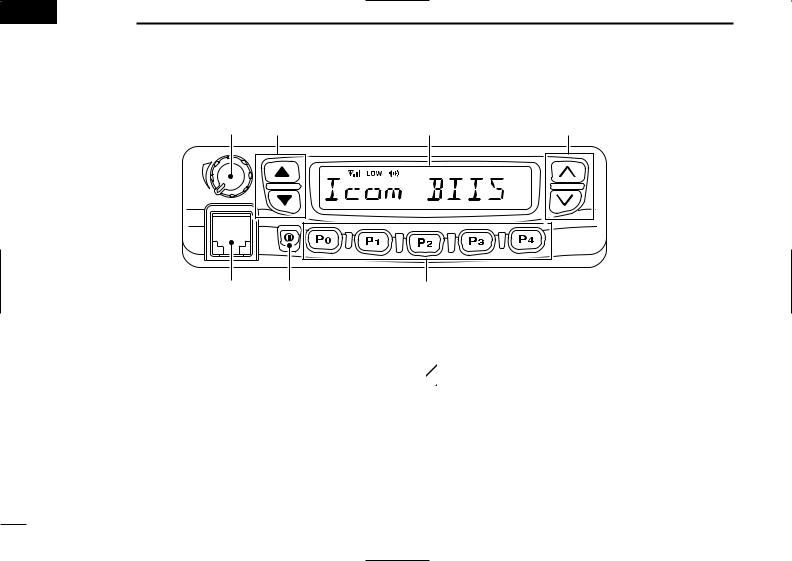
■ Front panel
q |
w |
e |
r |
u |
y |
t |
|
qAF VOLUME CONTROL KNOB
Rotate the knob to adjust the audio output level.
• Minimum audio level is pre-programmed.
wSTATUS UP/DOWN KEYS [Y]/[Z]
During the standby condition, push to display the transmit status indication and select a status number.
When a received SDM is displayed, push to cancel the automatic scroll and scroll the message manually.
When an SDM that contains more than 10 characters is displayed, push to scroll the message manually.
eFUNCTION DISPLAY (p. 3)
Displays a variety of information such as an operating channel number/name, code, status message.
 NOTE: The above functions depend on pre-program-
  ming.
ming.
rCHANNEL UP/DOWN KEYS [ ]/[
]/[ ]
]
During standby condition, push to select an operating channel.
After pushing [TX CODE CH], push to select a TX code channel.
After pushing [DTMF], push to select a DTMF channel.
While pushing [SCAN], push to select a scan group.
After pushing [DIGITAL], push to select a BIIS code, status number or SDM.
1

tDEALER-PROGRAMMABLE KEYS [P0] to [P4]
Desired functions can be programmed independently by your Dealer. However, the following functions are assigned as the default for BIIS operation.
[P0] : [CALL]
Push to transmit a 5-tone/BIIS call.
•Call transmission is necessary before you call another station, depending on your signalling system.
[P1] : [DIGITAL]
Push to select the call ID list, transmit message or standby condition. Toggles between queue channel and received message record after queue channel is selected.
Push for 1 sec. to select queue channel indication. [P4] : [MONI]
Activates one of (or two of) the following functions on each channel independently.
• Push and hold to unmute the channel (audio is emitted; ‘audible’ condition).
• Push to toggle the mute and unmute conditions (toggles
‘audible’ and ‘inaudible’).
•Push to mute the channel (sets to ‘inaudible’ only).
•Push to unmute the channel (sets to ‘audible’ only).
•Push after communication is finished to send a ‘reset code.’
•Push after communication is finished to send a ‘clear down code’ during BIIS operation on an MSK channel.
 NOTE: The unmute condition (‘audible’ condition)
  may automatically return to the mute condition
 (‘inaudible’ condition) after a specified period.
*No function is assigned for [P2] and [P3].
PANEL DESCRIPTION 1
yPOWER SWITCH [ ]
]
Push to turn the power ON and OFF.
•The following functions are available at power ON as options:
-Automatic scan start
-Password prompt
-Set mode
uMICROPHONE CONNECTOR
Connect the supplied microphone or optional DTMF microphone for SmarTrunk II™ operation here.
 NEVER connect non-specified microphones. The pin
assignments may be different and the transceiver may
 be damaged.
MICROPHONE
The supplied microphone has a PTT switch and a hanger hook.
•The following functions are available when the microphone is on or off hook:
-Automatic scan start when on hook.
-Automatic priority channel selection when off hook.
-Sets to ‘Inaudible’ condition (mute condition) when on hook.
-Sets to ‘Audible’ condition (un-mute condition) when off hook.
2
1 PANEL DESCRIPTION
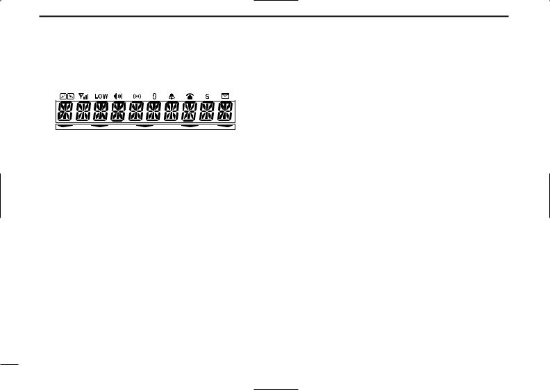
■ Function display
qw e r t y u i o !0 !1
!2 |
!3 |
qTRANSMIT INDICATOR
Appears while transmitting.
wRECEIVE INDICATOR
Appears when a signal is received, or the squelch is open.
eSIGNAL STRENGTH INDICATOR
Shows the relative signal strength while receiving signals.
rOUTPUT POWER INDICATOR
Appears when Low 2 or Low 1 is selected.
tAUDIBLE INDICATOR
Appears when the channel is in the ‘audible’ (unmute) condition.
Appears when the specific 5-tone/BIIS code is received.
yCOMPANDER INDICATOR
Appears when the compander function is activated.
uSCRAMBLER INDICATOR
Appears when the voice scrambler function is activated.
• Optional UT-109/110 is required.
iBELL INDICATOR
Appears/blinks when the specific 5-tone/BIIS code is received, according to the programming.
oCALL CODE MEMORY INDICATOR
Appears when the call code memory is selected.
!0SCROLL INDICATOR
Appears when a received SDM including more than 10 characters is displayed.
!1SDM INDICATOR
Appears when an SDM is received, or a transmit SDM is selected.
!2MULTI-FUNCTION INDICATOR
Shows the operating channel number and code simultaneously with the default setting.
The displayed information may differ according to the programming.
!3ACTIVATED KEY INDICATOR
Appears above the key assigned as the [DIGITAL] key when that key has been activated.
3

■ Programmable function keys
The following functions can be assigned to [P0], [P1], [P2], [P3], [P4], [Y], [Z], [ ] and [
 ] programmable function keys.
Consult your Icom Dealer or System operator for details concerning your transceivers programming.
In the following explanations, programmable function names are bracketed, the specific switch used to activate the function depends on programming.
[CH UP], [CH DN]
CH UP AND DOWN KEYS
•Select an operating channel.
•Select a transmit code channel after pushing the [TX CODE CH] key.
•Select a DTMF channel after pushing the [DTMF] key.
•Select a scan group while pushing and holding the [Scan A/B] key.
[BANK] BANK KEY
Select and determine a bank number.
•When the optional UT-105 is installed, push [BANK] then push [CH UP]/[CH DN] to select operating bank number, and then push [BANK] to determine the bank number.
[PRIO A], [PRIO A (Rewrite)], [PRIO B]
PRIORITY CHANNEL KEYS
Select Priority A or Priority B channel with each push.
Push and hold [Prio A (Rewrite)] to program the priority channel.
PANEL DESCRIPTION 1
[MR-CH1], [MR-CH2], [MR-CH3], [MR-CH4]
OPERATING CHANNEL KEYS
Select an operating channel directly.
[SCAN A], [SCAN B]
SCAN START/STOP KEYS
Push this key to start scanning; and push again to stop.
 NOTE: Place the microphone on hook to start
 scanning.
 Take the microphone off hook to stop scanning.
Push and hold this key to indicate the scan group, then push to select the desired group.
[SCAN Add/Del(Tag)]
SCAN TAG KEY
Adds or deletes the selected channel to the scan group.
[High/Low]
OUTPUT POWER SELECTION KEYS
Select the transmit output power temporarily or permanently depending on the pre-setting.
•Ask your Dealer or System Operator for the output power level for each selection.
[TA] TALK AROUND KEY
Turns the talk around function ON and OFF.
•The talk around function equalises the transmit frequency to the receive frequency for mobile-to-mobile communication.
4

1 PANEL DESCRIPTION
[MONI (Audi)]
MONITOR KEY
Activates one of (or two of) the following functions on each channel independently:
•Push and hold to un-mute the channel (audio is emitted; ‘Audible’ condition).
•Push to toggle the mute and un-mute conditions (toggles ‘Audible’ and ‘Inaudible’).
•Push to mute the channel (sets to ‘Inaudible’ only).
•Push to un-mute the channel (sets to ‘Audible’ only).
•Push after the communication is finished to send a ‘reset code’.
 NOTE: The un-mute condition (‘Audible’ condition)
may automatically return to the mute condition (‘In-
 audible‘ condition) after a specified period.
[TONE] C. TONE CHANNEL ENTER KEY
Push this key then input a continuous tone memory channel number using [CH UP]/[CH DN] keys to change the tone frequency.
[PA] PUBLIC ADDRESS KEY
When an optional OPC-617 ACC CABLE is installed, the audio output via the cable can be controlled from the transceiver separately from the [VOLUME] control.
•This audio output can be used as a ‘public address’ function when an external audio amplifier and speaker are connected additionally.
•Push this key, then speak into the microphone while pushing the PTT switch.
•The [CH UP]/[CH DN] keys allow you to set the audio output level from minimum to maximum.
[W/N] WIDE/NARROW KEY
Push [W/N] to toggle the IF passband width between wide or narrow.
[RX SP] EXTERNAL SPEAKER KEY
When external connections are made for the ‘public address’ function, the external speaker drive function is also available simultaneously. The received audio can be heard via the external speaker when this key is pushed.
•This function is useful when you are out of the vehicle.
•The audio output level is linked to the transceiver’s volume control.
[CALL], [CALL A (Code 30)], [CALL B (Code 29)]
CALL KEYS
Transmit a 5-tone/BIIS code.
•Call transmission is necessary before you call another station depending on your signalling system.
•The [CALL A] and/or [CALL B] keys may be available when your system employs selective ‘Individual/Group’ calls. Ask your Dealer which call is assigned to each key.
[LOCK] LOCK KEY
Electronically locks all programmable keys except the following:
•[CALL] (incl. [CALL A] and [CALL B]), [MONI] and [EMER] keys.
[DTMF Autodial]
DTMF AUTODIAL KEY
Push to select the DTMF channel.
Push for 1 sec. to transmit the selected DTMF code.
5

[RE-DIAL]
DTMF RE-DIAL KEY
Push this key to transmit the last-used DTMF code.
[EMER] EMERGENCY KEY
Push and hold to transmit an emergency call.
When [EMER (Silent)] is pushed, an emergency call is transmitted without a beep emission and LCD indication change.
•If you want to cancel the emergency call, push (or push and hold) the key again before transmitting the call.
•The emergency call is transmitted one time only or repeatedly until receiving a control code depending on the pre-setting.
[TX CODE Enter]
TX CODE ENTER KEY
Push to edit the selected MSK channel ID, 5-tone code or BIIS code.
The ID is overwritten when the MSK channel ID “Update” setting is set to “Enable.”
[TX CODE]
TX CODE CHANNEL SELECT KEY
Selects a 5-tone or BIIS TX code channel.
•Push and hold to change the contents of the TX code using the [CH UP]/[CH DN] keys.
•Push to select a TX code channel using the [CH UP]/[CH DN] keys after pushing this key.
•Push and hold to enter the code.
PANEL DESCRIPTION 1
[TX CODE CH Up], [TX CODE CH Down]
TX CODE CHANNEL UP/DOWN KEYS
Push to select a TX code channel directory.
[ID-MR Select]
ID MEMORY READ KEY
Recalls detected ID codes.
•Push this key, then push [CH UP]/[CH DN] for selection.
•Up to 5 ID’s are memorized.
Push and hold this key to erase all memorized IDs.
[SET] USER SET MODE KEY
Changes the contents of the items in the User Set mode.
•Push and hold [SET] for 1 sec. to enter set mode, push [SET] momentarily to select the item. Push [ ] and [
 ] to set the desired level/condition.
Push and hold [SET] again to exit set mode.
•User set mode is also available via the ‘Power ON function.’ Please refer to p. 10 also.
[HOOK SCAN]
HOOK SCAN KEY
When the hook on scan function is turned ON, push this key to stop scanning temporarily. Push this key again to re-start scanning.
[COMP] MIC COMPANDER KEY
Push to toggle the mic compander function ON or OFF.
6

1 PANEL DESCRIPTION
[SCRM] SCRAMBLER KEY
Push and hold to turn the voice scrambler function ON.
Push to turn the voice scrambler function OFF.
 NOTE:
NOTE:
• Optional UT-109 (#02) or UT-110 (#02) VOICE
SCRAMBLER UNIT is required.
- UT-109: Non-rolling type. 32 codes are available.
- UT-110: Rolling type. Provides higher communication
security. 1020 (4 groups × 255) codes are available.
 • This transceiver requires version #02 unit. Do not
install version #01, as it is not compatible.
 • UT-109 and UT-110 require some PC board modi-
fications. Please refer to ‘ UT-109/110 installation.’ (p. 29)
 • Please contact your Dealer for details.
[Special Func 1], [Special Func 2]
SPECIAL FUNCTION KEYS
Control the output signal level of the optional ports in the optional unit connector.
•Push this key, then select the desired DTMF channel using the [ ]/[
]/[ ] keys.
[STATUS UP], [STATUS DN]
STATUS UP/DOWN KEYS
During the standby condition, push to display the transmit status indication and select a status number.
When a received SDM is displayed, push to cancel the automatic scroll and scroll the message manually.
When an SDM that contains more than 10 characters is displayed, push to scroll the message manually.
[OPT OUT]
OPTION KEYS
Control the output signal level of the optional ports in the optional unit connector.
[DIGITAL]
DIGITAL FUNCTION KEY (BIIS operation only)
Push to select the call ID list, transmit message or standby condition. Toggles between queue channel and received message record indication after queue channel is selected.
Push for 1 sec. to select queue channel indication.
[GRP] TRUNKING GROUP KEY
Push to select the Trunking group.
[TURBO]TURBO SpeeDial A/B/C/D KEYS
During SmarTrunk II™ operation, when a key is assigned this function, push it to automatically dial a commonly used number with one push.
[ (CH UP)], [# (CH DN]
CALL/CLEAR-DOWN KEYS
Functions as [ ] and [#] keys on the DTMF microphone for SmarTrunk II™ operation.
• Push [ ] for call, push [#] for clear-down.
[ID SW] TRUNKING CALLER ID SW KEY
Push to display the received ID record in sequence (while in SmarTrunk 3G™ operation).
7
■ Turning power ON
qPush [ ] to turn the power ON.
•A power-up alert tone sounds for about 1 sec. and an opening message may appear.
wIf the transceiver is programmed for a start up passcode, input digit codes as directed by your Dealer.
•The keys in the table below can be used for password input:
•The transceiver detects numbers in the same block as identical. Therefore “01234” and “56789” are the same.
KEY |
[P0] |
[P1] |
[P2] |
[P3] |
[P4] |
|
|
|
|
|
|
|
|
NUMBER |
0 |
1 |
2 |
3 |
4 |
|
5 |
6 |
7 |
8 |
9 |
||
|
||||||
|
|
|
|
|
|
eWhen the “


 ” indication does not clear after inputting 4 digits, the input code number may be incorrect. Turn power off and start over in this case.
OPERATION 2 
■ Channel selection
Several types of channel selections are available. Methods may differ according to your system set up.
NON-BANK TYPE:
Push [CH UP]/[CH DN] to select the desired operating channel, in sequence; or, push one of the [CH 1] to [CH 4] to select a channel directly.
BANK-TYPE:
Push [BANK] to select the desired bank number.
AUTOMATIC SCAN TYPE:
Channel setting is not necessary for this type. When turning the power ON, the transceiver automatically starts scanning. Scanning stops when receiving a call or when taking the microphone off hook.
8
 Loading...