


INSTRUCTION MANUAL
VHF TRANSCEIVER
iF3/S
UHF TRANSCEIVER
iF4/S
This device complies with Part 15 of the FCC Rules. Operation is subject to the condition that this device does not cause harmful interference.

IMPORTANT |
TABLE OF CONTENTS |
READ ALL INSTRUCTIONS carefully and completely before using the transceiver.
SAVE THIS INSTRUCTION MANUAL. This manual contains important safety and operating instructions for the IC-F3,
IC-F3S, IC-F4 and IC-F4S.
CAUTIONS
NEVER allow the antenna to come close to, or touch, exposed body parts, especially the face or eyes while transmitting.
NEVER disassemble the transceiver. Incorrect reassembly may result in a fire hazard or electric shock.
NEVER operate the transceiver near unshielded electrical blasting caps or in an explosive area.
AVOID the use of chemical agents such as benzene or alcohol when cleaning—use a water-dampened cloth only.
For U.S.A. only
Caution: Changes or modifications to this transceiver, not expressly approved by Icom Inc., could void your authority to operate this transceiver under FCC regulations.
Versions of the IC-F3/IC-F4 which display “CE” on the serial number seal, comply with the essential requirements of the 89/336/EEC directive for Electromagnetic Compatibility.
IMPORTANT .......................................................................... |
i |
CAUTIONS ............................................................................ |
i |
TABLE OF CONTENTS ......................................................... |
i |
1 GETTING STARTED ......................................................... |
1 |
2 PANEL DESCRIPTION ..................................................... |
2 |
3 DEALER-PROGRAMMABLE FUNCTIONS ................. |
3–6 |
‘ General........................................................................ |
3 |
‘ Functions..................................................................... |
4 |
4 CONVENTIONAL OPERATION .................................... |
7–8 |
5 SmarTrunk IITM OPERATION ..................................... |
9–10 |
6 OPTIONAL INSTALLATION............................................ |
11 |
7 BATTERY PACKS ..................................................... |
12–16 |
‘ Battery pack replacement.......................................... |
12 |
‘ Cautions .................................................................... |
12 |
‘ Charging.................................................................... |
14 |
8 SPECIFICATIONS AND OPTIONS ................................. |
17 |
‘ Specifications ............................................................ |
17 |
‘ Options ...................................................................... |
17 |
SmarTrunk IITM is a trademark of SmarTrunk Systems,Inc.
i
GETTING STARTED 1 
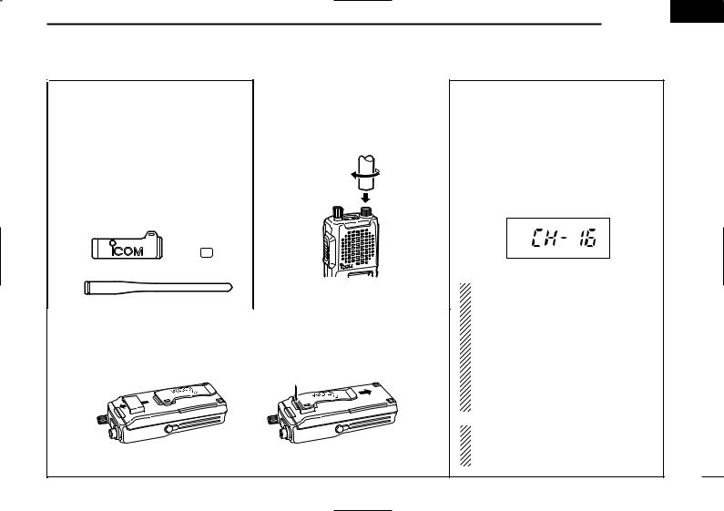
D UNPACKING
The transceiver comes supplied with the following accessories*.
q Flexible antenna w Belt clip
e 1922A REAR-SHEET
*The BP-196 BATTERY PACK comes attached to the transceiver.
w
e
q
D ANTENNA
The antenna screws onto the transceiver as illustrated below.
D BELT CLIP
Attach the belt clip to the transceiver as illustrated below.
Attach the belt-clip |
Release the belt-clip |
D TURNING POWER ON
Rotate the volume control to the 12 o’clock position.
•A power-up alert tone sounds for about 2 sec. and an opening message may appear.
(Above functions depend on pre-setting.) Then a channel number appears on the display.
MR
Channel number may differ from this.
NOTE: If the power-up alert tone does not sound or a channel number does not appear on the display, turn the transceiver OFF, check the battery, then turn the transceiver back ON.
If the power-up tone still does not sound or a channel number does not appear, charge the battery or replace it.
NOTE: To increment or decrement the displayed channel, push [Y] or [Z] keys.
1

 2 PANEL DESCRIPTION
IC-F3,IC-F4
 y
y
q 


 u
u
w 

 i e
i e 
 o
o
r 
t 
IC-F3S,IC-F4S
 y
y
q 
 u
u
w 

 i e
i e 
 o
o
r 
2

DEALER-PROGRAMMABLE FUNCTIONS 3 
qVOLUME CONTROL [OFF/VOL]
Turns power ON and adjusts the audio level. wPTT SWITCH [PTT]
Push and hold to transmit; release to receive. eUP/DOWN KEYS [Y]/[Z]
•Push to select the operating channel.
•Can be programmed as [ M]/[ #]. (SmarTrunk mode only)
rDEALER-PROGRAMABLE KEYS
[P0]/[P1]/[P2]/[P3]/[A]/[B]/[C]/[D]/ [Ω]/[ ]/[–] Can each be programmed for one of
several functions by your Icom Dealer (see right). tKEYPAD
Used to enter DTMF codes, the operating channel, etc. yANTENNA CONNECTOR
Connects the supplied antenna. u[SP]/[MIC] JACK
Connect optional speaker-microphone. iACTIVITY LED
Lights red while transmiting. oFUNCTION DISPLAY
Displays the following the information:
•CH number.
•5-tone indication.
•Low-battery indication.
•DTMF numbers.
•Low-power indication.
•Skip-ch indication.
•Audible indication.
NOTE: Above functions depend on presetting.
■ General
Consult your Icom Dealer or System operator for details concerning your transceiver’s programming. When available, programmed functions are assigned to [P0], [P1], [P2], [P3], [A]*1, [B]*1, [C]*1, [D]*1, [Ω]*1, [ ]*1, [ – ]*2 and [Y]/[Z]*3.
*1: IC-F3/IC-F4 only. *2: IC-F3S/IC-F4S only.
*3: SmarTrunk II mode when assigned [ M]/[ #] functions only.
DProgrammable key reference.
IC-F3/IC-F4
[ Y ] |
|
[ ] |
|
|
|
|
|
[ Z ] |
|
[ Ω ] |
|
|
|
|
|
[ P0 ] |
|
[ A ] |
|
|
|
|
|
[ P1 ] |
|
[ B ] |
|
|
|
|
|
[ P2 ] |
|
[ C ] |
|
|
|
|
|
[ P3 ] |
|
[ D ] |
|
|
|
|
|
IC-F3S/IC-F4S |
|
|
|
|
|
||
[ Y ] |
|
[ P0 ] |
|
|
|
|
|
[ Z ] |
|
[ P1 ] |
|
|
|
|
|
[ – ] |
|
[ P2 ] |
|
|
|
|
|
|
|
[ P3 ] |
|
|
|
|
|
3

3 DEALER-PROGRAMMABLE FUNCTIONS
■ Functions
In the following explanations, programmable function names are bracketed, the specific switch used to activate the function depends on programming.
DKEYPAD LOCK FUNCTION
This function locks access to all programmable switches (except the switch assigned the lock function).
To toggle the lock function ON and OFF:
Push and hold the [LOCK] switch for 1 sec.
•“  ”appears while the lock function is ON.
•This function may be inhibited on some channels.
DPRIORITY CHANNEL
This function is used to select a pre-programmed channel at the push of a switch.
To select the priority channel:
Push the [PRIORITY] switch.
•“PRIO” appears briefly, then the priority channel is automatically se-
lected.
DSCAN FUNCTION
The scan function allows you to search a pre-programmed group of channels for signals.
To start/stop scan:
Push the [SCAN] switch.
•Scan pauses on a channel when receiving a signal.
•Depending on programming, a message may appear while scanning.
•“Lockout SCAN" (pre-programmed list SCAN) or “Priority SCAN” can be pre-programmed.
•When the “Power-save function” is activated, the transceiver checks all pre-programmed channels then returns to the “Power-save function” again.
DBEEP FUNCTION
This function provides confirmation beep tones when pushing switches.
To toggle the function ON and OFF:
Push the [BEEP] switch.
4
 Loading...