


IC-F2610
INSTRUCTION MANUAL
iF1610
VHF TRANSCEIVER
iF2610
UHF TRANSCEIVER

ii
IMPORTANT
READ ALL INSTRUCTIONS carefully and com-
pletely before using the transceiver.
SAVE THIS INSTRUCTION MANUAL—This in-
struction manual contains important operating instructions for
the IC-F1610 VHF TRANSCEIVER or IC-F2610 UHF
TRANSCEIVER.
EXPLICIT DEFINITIONS
Versions of the transceiver which display the “CE” on the se-
rial number seal, comply with the essential requirements of
the 89/336/EEC directive for Electromagnetic Compatibility.
RWARNING! NEVER connect the transceiver to an
AC outlet. This may pose a fire hazard or result in an electric
shock.
NEVER connect the transceiver to a power source of more
than 16 V DC such as a 24 V battery. This connection will ruin
the transceiver.
NEVER cut the DC power cable between the DC plug and
fuse holder. If an incorrect connection is made after cutting,
the transceiver might be damaged.
NEVER place the transceiver where normal operation of
the vehicle may be hindered or where it could cause bodily
injury.
Place unit in a secure place to avoid inadvertent use by chil-
dren.
NEVER expose the transceiver to rain, snow or any liquids.
USE supplied microphones only. Other microphones have
different pin assignments and may damage the transceiver.
SmarTrunk II™ is a trademark of SmarTrunk Systems, Inc.
CAUTIONS
WORD DEFINITION
RWARNING
Personal injury, fire hazard or electric
shock may occur.
CAUTION
Equipment damage may occur.
NOTE
If disregarded, inconvenience only. No risk
of personal injury, fire or electric shock.

DO NOT connect the transceiver to a power source using
reverse polarity. This connection will not only blow fuses but
also may damage the transceiver.
DO NOT use or place the transceiver in areas with tem-
peratures below –20°C or above +55°C or, in areas subject
to direct sunlight, such as the dashboard.
AVOID operating the transceiver without running the vehi-
cle’s engine. The vehicle’s battery will quickly run out if the
transceiver is in transmission while the vehicle’s engine is off.
AVOID placing the transceiver is excessively dusty envi-
ronments.
AVOID placing the transceiver against walls. This will ob-
struct heat dissipation.
AVOID the use of chemical agents such as benzine or al-
cohol when cleaning, as they can damage the transceiver’s
surfaces.
BE CAREFUL! The transceiver will become hot when
operating continuously for long periods.
iii
iv
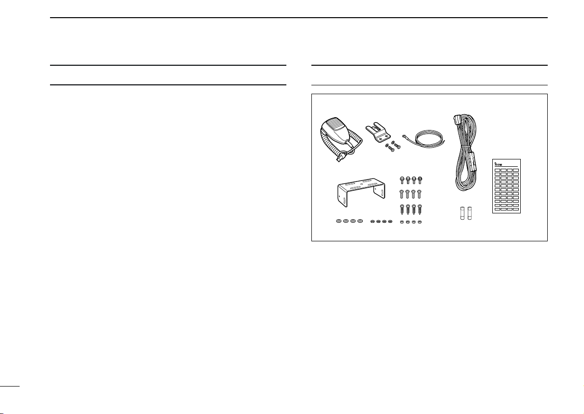
SUPPLIED ACCESSORIES
qw
r
t
y
u
i
o!0 !1
!2
!3
e
LCD-STICKER
q Microphone (HM-100) . . . . 1
w Microphone hanger and
screw set . . . . . . . . . . . 1 set
e Microphone cable . . . . . . . 1
r DC power cable
(OPC-345) . . . . . . . . . . . . . 1
t Mounting bracket . . . . . . . . 1
y Bracket bolts . . . . . . . . . . . 4
u Mounting screws (M5 × 12) 4
i Self-tapping screws
(M5 × 20) . . . . . . . . . . . . . . 4
o Flat washers . . . . . . . . . . . 4
!0 Spring washers . . . . . . . . . 4
!1 Nuts . . . . . . . . . . . . . . . . . . 4
!2 Fuses (15A) . . . . . . . . . . . . 2
!3 Function name stickers 1 set
D Function name stickers
Use these to label the programmable function keys ([P0] to
[P4]) according to their assigned functions.
TABLE OF CONTENTS
IMPORTANT . . . . . . . . . . . . . . . . . . . . . . . . . . . . . . . . . . . . ii
EXPLICIT DEFINITIONS . . . . . . . . . . . . . . . . . . . . . . . . . . . ii
CAUTIONS . . . . . . . . . . . . . . . . . . . . . . . . . . . . . . . . . . . . . ii
TABLE OF CONTENTS . . . . . . . . . . . . . . . . . . . . . . . . . . . iv
SUPPLIED ACCESSORIES . . . . . . . . . . . . . . . . . . . . . . . . iv
1 PANEL DESCRIPTION . . . . . . . . . . . . . . . . . . . . . . . . 1–6
■ Front panel . . . . . . . . . . . . . . . . . . . . . . . . . . . . . . . . . . 1
■ Programmable function keys . . . . . . . . . . . . . . . . . . . . 2
■ Function display . . . . . . . . . . . . . . . . . . . . . . . . . . . . . . 6
2 OPERATION . . . . . . . . . . . . . . . . . . . . . . . . . . . . . . . . 7–9
■ Turning power on . . . . . . . . . . . . . . . . . . . . . . . . . . . . . 7
■ Channel selection . . . . . . . . . . . . . . . . . . . . . . . . . . . . . 7
■ Receiving and transmitting . . . . . . . . . . . . . . . . . . . . . . 8
3 CONNECTION AND INSTALLATION . . . . . . . . . . . 10–13
■ Rear panel connections . . . . . . . . . . . . . . . . . . . . . . . 10
■ Mounting . . . . . . . . . . . . . . . . . . . . . . . . . . . . . . . . . . 12
■ Seaparation . . . . . . . . . . . . . . . . . . . . . . . . . . . . . . . . 12
■ Optional UT-105 installation . . . . . . . . . . . . . . . . . . . . 13
4 OPTIONAL SmarTrunk II™ OPERATION . . . . . . . 14–16
■ SmarTrunk II™ and conventional modes . . . . . . . . . . 14
■ SmarTrunk II™ operation . . . . . . . . . . . . . . . . . . . . . . 14
5 OPTIONS . . . . . . . . . . . . . . . . . . . . . . . . . . . . . . . . . . . . 17
NOTE: Some versions include the SP-22
EXTERNAL SPEAKER
.
1
1
PANEL DESCRIPTION
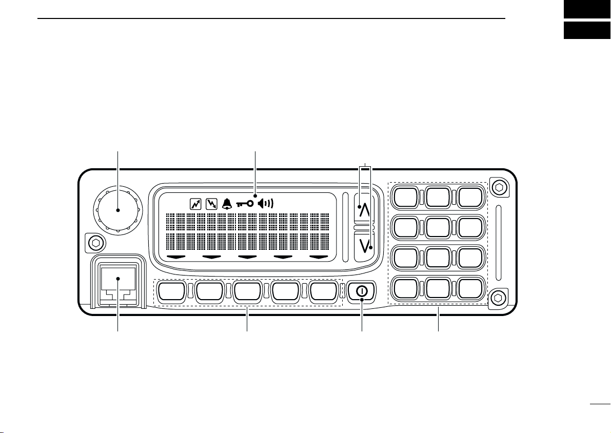
■ Front panel
1
P
4P3P2P1P0
23
456
789
M
0#
LOW
VOLUME CONTROL FUNCTION DISPLAY (p. 6) CH UP/DOWN KEYS (p. 2)
(programmable)
MICROPHONE
CONNECTOR
POWER
SWITCH
PROGRAMMABLE
FUNCTION KEYS
(pgs. 2–6)
KEYPAD

2
1
PANEL DESCRIPTION
VOLUME CONTROL
Adjusts the audio output
• Minimum audio level (when setting control maximum counter clock-
wise) is pre-programmed.
CHANNEL UP/DOWN KEYS [ ]/[ ]([CH UP]/[CH DN])
Push to select an operating channel.
• Can be programmed for one of several functions by your dealer.
POWER SWITCH
Turns the power on and off.
• The following functions are available at power on as options:
➥ Automatic scan start
➥ Password prompt
KEYPAD
The keypad allows you to enter digits to:
➥ Select memory channels
➥ Select tone channels
➥ Select DTMF codes (during transmit)
➥ Set SmarTrunk II™ codes
MICROPHONE CONNECTOR
Connects the supplied microphone or optional DTMF micro-
phone for SmarTrunk II™ operation.
NEVER connect other microphones. The pin assignments
may be different and the transceiver may be damaged.
MICROPHONE
The supplied microphone has a PTT switch and a cradle. The
following functions are available when the microphone is
taken off the cradle or put back on hook:
➥ Automatic scan start when putting on hook
➥ Automatic priority channel selection when taken off hook
➥ Set to ‘inaudible’ (mute condition) when putting on hook
➥ Set to ‘audible’ (unmute condition) when taken off hook
■ Programmable keys
The following functions can be assigned to the programmable
function keys. Assigned function names can be affixed to the
corresponding keys using the supplied stickers*.
*Some functions do not have supplied stickers.
D Programmable functions with supplied
stickers
MEMORY CHANNEL KEYS
Select a memory channel directly.
MR–1
MR–2
MR–3
MR–4

3
1
PANEL DESCRIPTION
BANK KEY
Selects a memory bank.
PRIORITY CHANNEL KEYS
Select priority A or priority B channel.
SCAN KEYS
Start/stop scan A or scan B.
SCAN TAG KEY
Adds or deletes the selected channel to the scan
group.
•“ ” appears above the [TAG] key when the channel belongs to
the scan group.
MONITOR KEY
Activates one of (or two of) the following functions
on each channel independently.
• Push and hold the key to unmute the channel (audio is emitted; ‘au-
dible’ condition).
• Push the key to toggle the mute and unmute conditions (toggles ‘au-
dible’ and ‘inaudible’).
• Push the key to mute the channel (sets to ‘inaudible’ only).
• Push the key to unmute the channel (sets to ‘audible’ only).
• Push the key after communication is finished to send a ‘reset code.’
☞ NOTE: The unmute condition (‘audible’ conditions) may
automatically return to the mute condition (‘inaudible’ con-
dition) after a specified period.
PUBLIC ADDRESS KEY
When an optional OPC-617
ACC CABLE
is installed,
the audio output via the cable can be controlled
from the transceiver separately from the [VOLUME] control.
• This audio output can be used as a ‘public address’ function when
an external audio amplifier and speaker are connected additionally.
• Push this key, then speak into the microphone while pushing the
PTT switch.
• The [CH UP]/[CH DN] keys allow you to set the audio output level
from minimum to maximum.
EXTERNAL SPEAKER KEY
When external connections are made for the ‘public
address’ function, the external speaker drive func-
tion is also available simultaneously. The received audio can
be heard via the external speaker when this key is pushed.
• This function is useful when you are out of the vehicle.
• The audio output level is linked to the transceiver’s volume control.
LOCK KEY
Electronically locks all programmable keys except
BANK
PRI A
SCN A
TAG
MONI
PRI B
SCN B
PA
SP
LOCK
 Loading...