


pavilion dv8
Table of contents
 Loading...
HP Pavilion dv8 Entertainment PC
Maintenance and Service Guide
Document Part Number: 580213-001
September 2009
This guide is a troubleshooting reference used for maintaining and servicing the computer. It provides
comprehensive information on identifying computer features, components, and spare parts; troubleshooting
computer problems; and performing computer disassembly procedures.

© Copyright 2009 Hewlett-Packard Development Company, L.P.
Bluetooth is a trademark owned by its proprietor and used by Hewlett-Packard Company under license. Intel and Core are trademarks or
registered trademarks of Intel Corporation or its subsidiaries in the United States and other countries. Microsoft and Windows are U.S.
registered trademarks of Microsoft Corporation. SD Logo is a trademark of its proprietor.
The information contained herein is subject to change without notice. The only warranties for HP products and services are set forth in
the express warranty statements accompanying such products and services. Nothing herein should be construed as constituting an
additional warranty. HP shall not be liable for technical or editorial errors or omissions contained herein.
First Edition: September 2009
Document Part Number: 580213-001

Safety warning notice
Å
WARNING: To reduce the possibility of heat-related injuries or of overheating the computer, do not place the computer directly
on your lap or obstruct the computer air vents. Use the computer only on a hard, flat surface. Do not allow another hard surface,
such as an adjoining optional printer, or a soft surface, such as pillows or rugs or clothing, to block airflow. Also, do not allow
the AC adapter to contact the skin or a soft surface, such as pillows or rugs or clothing, during operation. The computer and the
AC adapter comply with the user-accessible surface temperature limits defined by the International Standard for Safety of
Information Technology Equipment (IEC 60950).

Maintenance and Service Guide v
Contents
1 Product description
2 External component identification
Top components. . . . . . . . . . . . . . . . . . . . . . . . . . . . . . . . . . . . . . . . . . . . . . . . . . . . . . . . . . . . . . . . . . . . . . 2–2
Display components . . . . . . . . . . . . . . . . . . . . . . . . . . . . . . . . . . . . . . . . . . . . . . . . . . . . . . . . . . . . . . . 2–2
Buttons, speakers, and fingerprint reader . . . . . . . . . . . . . . . . . . . . . . . . . . . . . . . . . . . . . . . . . . . . . . . 2–3
Keys . . . . . . . . . . . . . . . . . . . . . . . . . . . . . . . . . . . . . . . . . . . . . . . . . . . . . . . . . . . . . . . . . . . . . . . . . . . 2–5
Lights . . . . . . . . . . . . . . . . . . . . . . . . . . . . . . . . . . . . . . . . . . . . . . . . . . . . . . . . . . . . . . . . . . . . . . . . . . 2–6
Pointing devices . . . . . . . . . . . . . . . . . . . . . . . . . . . . . . . . . . . . . . . . . . . . . . . . . . . . . . . . . . . . . . . . . . 2–8
Front components. . . . . . . . . . . . . . . . . . . . . . . . . . . . . . . . . . . . . . . . . . . . . . . . . . . . . . . . . . . . . . . . . . . . . 2–9
Right-side components. . . . . . . . . . . . . . . . . . . . . . . . . . . . . . . . . . . . . . . . . . . . . . . . . . . . . . . . . . . . . . . . 2–10
Left-side components . . . . . . . . . . . . . . . . . . . . . . . . . . . . . . . . . . . . . . . . . . . . . . . . . . . . . . . . . . . . . . . . . 2–11
Rear component . . . . . . . . . . . . . . . . . . . . . . . . . . . . . . . . . . . . . . . . . . . . . . . . . . . . . . . . . . . . . . . . . . . . . 2–11
Bottom components . . . . . . . . . . . . . . . . . . . . . . . . . . . . . . . . . . . . . . . . . . . . . . . . . . . . . . . . . . . . . . . . . . 2–12
3 Illustrated parts catalog
Service tag . . . . . . . . . . . . . . . . . . . . . . . . . . . . . . . . . . . . . . . . . . . . . . . . . . . . . . . . . . . . . . . . . . . . . . . . . . 3–1
Computer major components . . . . . . . . . . . . . . . . . . . . . . . . . . . . . . . . . . . . . . . . . . . . . . . . . . . . . . . . . . . . 3–2
Display assembly components . . . . . . . . . . . . . . . . . . . . . . . . . . . . . . . . . . . . . . . . . . . . . . . . . . . . . . . . . . . 3–6
Mass storage devices . . . . . . . . . . . . . . . . . . . . . . . . . . . . . . . . . . . . . . . . . . . . . . . . . . . . . . . . . . . . . . . . . . 3–7
Plastics Kit . . . . . . . . . . . . . . . . . . . . . . . . . . . . . . . . . . . . . . . . . . . . . . . . . . . . . . . . . . . . . . . . . . . . . . . . . . 3–8
Miscellaneous parts . . . . . . . . . . . . . . . . . . . . . . . . . . . . . . . . . . . . . . . . . . . . . . . . . . . . . . . . . . . . . . . . . . . 3–9
Sequential part number listing . . . . . . . . . . . . . . . . . . . . . . . . . . . . . . . . . . . . . . . . . . . . . . . . . . . . . . . . . . 3–10
4 Removal and replacement procedures
Preliminary replacement requirements . . . . . . . . . . . . . . . . . . . . . . . . . . . . . . . . . . . . . . . . . . . . . . . . . . . . 4–1
Tools required . . . . . . . . . . . . . . . . . . . . . . . . . . . . . . . . . . . . . . . . . . . . . . . . . . . . . . . . . . . . . . . . . . . . 4–1
Service considerations. . . . . . . . . . . . . . . . . . . . . . . . . . . . . . . . . . . . . . . . . . . . . . . . . . . . . . . . . . . . . . 4–1
Grounding guidelines . . . . . . . . . . . . . . . . . . . . . . . . . . . . . . . . . . . . . . . . . . . . . . . . . . . . . . . . . . . . . . 4–2
Component replacement procedures . . . . . . . . . . . . . . . . . . . . . . . . . . . . . . . . . . . . . . . . . . . . . . . . . . . . . . 4–5
Service tag . . . . . . . . . . . . . . . . . . . . . . . . . . . . . . . . . . . . . . . . . . . . . . . . . . . . . . . . . . . . . . . . . . . . . . . . . . 4–5
Computer feet . . . . . . . . . . . . . . . . . . . . . . . . . . . . . . . . . . . . . . . . . . . . . . . . . . . . . . . . . . . . . . . . . . . . 4–6
Battery. . . . . . . . . . . . . . . . . . . . . . . . . . . . . . . . . . . . . . . . . . . . . . . . . . . . . . . . . . . . . . . . . . . . . . . . . . 4–7
Optical drive . . . . . . . . . . . . . . . . . . . . . . . . . . . . . . . . . . . . . . . . . . . . . . . . . . . . . . . . . . . . . . . . . . . . . 4–8
Mass storage device . . . . . . . . . . . . . . . . . . . . . . . . . . . . . . . . . . . . . . . . . . . . . . . . . . . . . . . . . . . . . . 4–10
TV tuner module . . . . . . . . . . . . . . . . . . . . . . . . . . . . . . . . . . . . . . . . . . . . . . . . . . . . . . . . . . . . . . . . . 4–13
RTC battery. . . . . . . . . . . . . . . . . . . . . . . . . . . . . . . . . . . . . . . . . . . . . . . . . . . . . . . . . . . . . . . . . . . . . 4–15
Memory module . . . . . . . . . . . . . . . . . . . . . . . . . . . . . . . . . . . . . . . . . . . . . . . . . . . . . . . . . . . . . . . . . 4–16
WLAN module . . . . . . . . . . . . . . . . . . . . . . . . . . . . . . . . . . . . . . . . . . . . . . . . . . . . . . . . . . . . . . . . . . 4–17
Switch cover . . . . . . . . . . . . . . . . . . . . . . . . . . . . . . . . . . . . . . . . . . . . . . . . . . . . . . . . . . . . . . . . . . . . 4–21
Keyboard cover . . . . . . . . . . . . . . . . . . . . . . . . . . . . . . . . . . . . . . . . . . . . . . . . . . . . . . . . . . . . . . . . . . 4–23
Power button board . . . . . . . . . . . . . . . . . . . . . . . . . . . . . . . . . . . . . . . . . . . . . . . . . . . . . . . . . . . . . . . 4–25

vi Maintenance and Service Guide
Contents
Bluetooth module . . . . . . . . . . . . . . . . . . . . . . . . . . . . . . . . . . . . . . . . . . . . . . . . . . . . . . . . . . . . . . . . 4–26
Keyboard. . . . . . . . . . . . . . . . . . . . . . . . . . . . . . . . . . . . . . . . . . . . . . . . . . . . . . . . . . . . . . . . . . . . . . . 4–27
Power button board cable . . . . . . . . . . . . . . . . . . . . . . . . . . . . . . . . . . . . . . . . . . . . . . . . . . . . . . . . . . 4–30
Bluetooth module cable . . . . . . . . . . . . . . . . . . . . . . . . . . . . . . . . . . . . . . . . . . . . . . . . . . . . . . . . . . . 4–31
LED board cable . . . . . . . . . . . . . . . . . . . . . . . . . . . . . . . . . . . . . . . . . . . . . . . . . . . . . . . . . . . . . . . . . 4–32
Speaker assembly . . . . . . . . . . . . . . . . . . . . . . . . . . . . . . . . . . . . . . . . . . . . . . . . . . . . . . . . . . . . . . . . 4–33
Display assembly . . . . . . . . . . . . . . . . . . . . . . . . . . . . . . . . . . . . . . . . . . . . . . . . . . . . . . . . . . . . . . . . 4–34
Top cover . . . . . . . . . . . . . . . . . . . . . . . . . . . . . . . . . . . . . . . . . . . . . . . . . . . . . . . . . . . . . . . . . . . . . . 4–41
TouchPad on/off button board . . . . . . . . . . . . . . . . . . . . . . . . . . . . . . . . . . . . . . . . . . . . . . . . . . . . . . 4–46
System board. . . . . . . . . . . . . . . . . . . . . . . . . . . . . . . . . . . . . . . . . . . . . . . . . . . . . . . . . . . . . . . . . . . . 4–48
Fan. . . . . . . . . . . . . . . . . . . . . . . . . . . . . . . . . . . . . . . . . . . . . . . . . . . . . . . . . . . . . . . . . . . . . . . . . . . . 4–51
Subwoofer . . . . . . . . . . . . . . . . . . . . . . . . . . . . . . . . . . . . . . . . . . . . . . . . . . . . . . . . . . . . . . . . . . . . . . 4–53
Audio/infrared board. . . . . . . . . . . . . . . . . . . . . . . . . . . . . . . . . . . . . . . . . . . . . . . . . . . . . . . . . . . . . . 4–55
USB board. . . . . . . . . . . . . . . . . . . . . . . . . . . . . . . . . . . . . . . . . . . . . . . . . . . . . . . . . . . . . . . . . . . . . . 4–57
Power connector cable . . . . . . . . . . . . . . . . . . . . . . . . . . . . . . . . . . . . . . . . . . . . . . . . . . . . . . . . . . . . 4–58
TV tuner module cable . . . . . . . . . . . . . . . . . . . . . . . . . . . . . . . . . . . . . . . . . . . . . . . . . . . . . . . . . . . . 4–59
Fan/heat sink assembly . . . . . . . . . . . . . . . . . . . . . . . . . . . . . . . . . . . . . . . . . . . . . . . . . . . . . . . . . . . . 4–60
Processor . . . . . . . . . . . . . . . . . . . . . . . . . . . . . . . . . . . . . . . . . . . . . . . . . . . . . . . . . . . . . . . . . . . . . . . 4–63
5 Setup Utility
Starting Setup Utility . . . . . . . . . . . . . . . . . . . . . . . . . . . . . . . . . . . . . . . . . . . . . . . . . . . . . . . . . . . . . . . . . . 5–1
Using Setup Utility. . . . . . . . . . . . . . . . . . . . . . . . . . . . . . . . . . . . . . . . . . . . . . . . . . . . . . . . . . . . . . . . . . . . 5–1
Changing the language of Setup Utility . . . . . . . . . . . . . . . . . . . . . . . . . . . . . . . . . . . . . . . . . . . . . . . . 5–1
Navigating and selecting in Setup Utility . . . . . . . . . . . . . . . . . . . . . . . . . . . . . . . . . . . . . . . . . . . . . . . 5–2
Displaying system information . . . . . . . . . . . . . . . . . . . . . . . . . . . . . . . . . . . . . . . . . . . . . . . . . . . . . . . 5–2
Restoring default settings in Setup Utility . . . . . . . . . . . . . . . . . . . . . . . . . . . . . . . . . . . . . . . . . . . . . . 5–2
Exiting Setup Utility . . . . . . . . . . . . . . . . . . . . . . . . . . . . . . . . . . . . . . . . . . . . . . . . . . . . . . . . . . . . . . . 5–3
Setup Utility menus . . . . . . . . . . . . . . . . . . . . . . . . . . . . . . . . . . . . . . . . . . . . . . . . . . . . . . . . . . . . . . . . . . . 5–3
Main menu . . . . . . . . . . . . . . . . . . . . . . . . . . . . . . . . . . . . . . . . . . . . . . . . . . . . . . . . . . . . . . . . . . . . . . 5–3
Security menu . . . . . . . . . . . . . . . . . . . . . . . . . . . . . . . . . . . . . . . . . . . . . . . . . . . . . . . . . . . . . . . . . . . . 5–3
System Configuration menu . . . . . . . . . . . . . . . . . . . . . . . . . . . . . . . . . . . . . . . . . . . . . . . . . . . . . . . . . 5–4
Diagnostics menu . . . . . . . . . . . . . . . . . . . . . . . . . . . . . . . . . . . . . . . . . . . . . . . . . . . . . . . . . . . . . . . . . 5–4
6 Specifications
Computer specifications. . . . . . . . . . . . . . . . . . . . . . . . . . . . . . . . . . . . . . . . . . . . . . . . . . . . . . . . . . . . . . . . 6–1
18.4-inch display specifications. . . . . . . . . . . . . . . . . . . . . . . . . . . . . . . . . . . . . . . . . . . . . . . . . . . . . . . . . . 6–2
Hard drive specifications . . . . . . . . . . . . . . . . . . . . . . . . . . . . . . . . . . . . . . . . . . . . . . . . . . . . . . . . . . . . . . . 6–2
Blu-ray ROM DVD±RW SuperMulti DL Drive specifications . . . . . . . . . . . . . . . . . . . . . . . . . . . . . . . . . 6–3
System DMA specifications. . . . . . . . . . . . . . . . . . . . . . . . . . . . . . . . . . . . . . . . . . . . . . . . . . . . . . . . . . . . . 6–3
System memory map specifications. . . . . . . . . . . . . . . . . . . . . . . . . . . . . . . . . . . . . . . . . . . . . . . . . . . . . . . 6–4
System interrupt specifications . . . . . . . . . . . . . . . . . . . . . . . . . . . . . . . . . . . . . . . . . . . . . . . . . . . . . . . . . . 6–4
System I/O address specifications . . . . . . . . . . . . . . . . . . . . . . . . . . . . . . . . . . . . . . . . . . . . . . . . . . . . . . . . 6–5

Contents
Maintenance and Service Guide vii
7 Screw listing
Phillips PM2.5×7.0 screw . . . . . . . . . . . . . . . . . . . . . . . . . . . . . . . . . . . . . . . . . . . . . . . . . . . . . . . . . . . . . . 7–1
Phillips PM2.0×4.0 screw . . . . . . . . . . . . . . . . . . . . . . . . . . . . . . . . . . . . . . . . . . . . . . . . . . . . . . . . . . . . . . 7–5
Phillips PM2.5×4.0 screw . . . . . . . . . . . . . . . . . . . . . . . . . . . . . . . . . . . . . . . . . . . . . . . . . . . . . . . . . . . . . 7–12
Phillips PM2.5×6.0 captive screw . . . . . . . . . . . . . . . . . . . . . . . . . . . . . . . . . . . . . . . . . . . . . . . . . . . . . . . 7–13
Phillips PM3.0×4.0 screw . . . . . . . . . . . . . . . . . . . . . . . . . . . . . . . . . . . . . . . . . . . . . . . . . . . . . . . . . . . . . 7–14
Phillips PM2.5×5.0 broadhead screw . . . . . . . . . . . . . . . . . . . . . . . . . . . . . . . . . . . . . . . . . . . . . . . . . . . . 7–15
Phillips PM2.0×11.0 captive screw . . . . . . . . . . . . . . . . . . . . . . . . . . . . . . . . . . . . . . . . . . . . . . . . . . . . . . 7–16
Phillips PM2.5×5.0 captive screw . . . . . . . . . . . . . . . . . . . . . . . . . . . . . . . . . . . . . . . . . . . . . . . . . . . . . . . 7–17
8 Backup and recovery
Creating recovery discs . . . . . . . . . . . . . . . . . . . . . . . . . . . . . . . . . . . . . . . . . . . . . . . . . . . . . . . . . . . . . . . . 8–1
Backing up your information . . . . . . . . . . . . . . . . . . . . . . . . . . . . . . . . . . . . . . . . . . . . . . . . . . . . . . . . . . . . 8–2
Using Windows Backup and Restore . . . . . . . . . . . . . . . . . . . . . . . . . . . . . . . . . . . . . . . . . . . . . . . . . . 8–3
Using system restore points . . . . . . . . . . . . . . . . . . . . . . . . . . . . . . . . . . . . . . . . . . . . . . . . . . . . . . . . . 8–3
Performing a recovery . . . . . . . . . . . . . . . . . . . . . . . . . . . . . . . . . . . . . . . . . . . . . . . . . . . . . . . . . . . . . . . . . 8–4
Recovering from the recovery discs . . . . . . . . . . . . . . . . . . . . . . . . . . . . . . . . . . . . . . . . . . . . . . . . . . . 8–4
Recovering from the dedicated recovery partition (select models only) . . . . . . . . . . . . . . . . . . . . . . . 8–4
9 Connector pin assignments
1394 . . . . . . . . . . . . . . . . . . . . . . . . . . . . . . . . . . . . . . . . . . . . . . . . . . . . . . . . . . . . . . . . . . . . . . . . . . . . . . . 9–1
Audio-in (microphone). . . . . . . . . . . . . . . . . . . . . . . . . . . . . . . . . . . . . . . . . . . . . . . . . . . . . . . . . . . . . . . . . 9–2
Audio-out (headphone) . . . . . . . . . . . . . . . . . . . . . . . . . . . . . . . . . . . . . . . . . . . . . . . . . . . . . . . . . . . . . . . . 9–2
External monitor. . . . . . . . . . . . . . . . . . . . . . . . . . . . . . . . . . . . . . . . . . . . . . . . . . . . . . . . . . . . . . . . . . . . . . 9–3
HDMI . . . . . . . . . . . . . . . . . . . . . . . . . . . . . . . . . . . . . . . . . . . . . . . . . . . . . . . . . . . . . . . . . . . . . . . . . . . . . . 9–4
RJ-45 (network) . . . . . . . . . . . . . . . . . . . . . . . . . . . . . . . . . . . . . . . . . . . . . . . . . . . . . . . . . . . . . . . . . . . . . . 9–5
Universal Serial Bus. . . . . . . . . . . . . . . . . . . . . . . . . . . . . . . . . . . . . . . . . . . . . . . . . . . . . . . . . . . . . . . . . . . 9–6
10Power cord set requirements
Requirements for all countries and regions . . . . . . . . . . . . . . . . . . . . . . . . . . . . . . . . . . . . . . . . . . . . . . . . 10–1
Requirements for specific countries and regions . . . . . . . . . . . . . . . . . . . . . . . . . . . . . . . . . . . . . . . . . . . . 10–2
11Recycling
Battery . . . . . . . . . . . . . . . . . . . . . . . . . . . . . . . . . . . . . . . . . . . . . . . . . . . . . . . . . . . . . . . . . . . . . . . . . . . . 11–1
Display . . . . . . . . . . . . . . . . . . . . . . . . . . . . . . . . . . . . . . . . . . . . . . . . . . . . . . . . . . . . . . . . . . . . . . . . . . . . 11–1
Index
Index

Maintenance and Service Guide 1–1
1
Product description
Category Description
Product name HP Pavilion dv8 Entertainment PC
Processors Intel® Core™ i7-820QM 1.73-GHz processor (SC turbo up to 3.06 GHz)
Intel Core i7-720QM 1.60-GHz processor (SC turbo up to 2.80 GHz)
Chipset Intel 5 Series express chipsets
PM55 - platform controller hub (PCH) Peak-M
Graphics nVidia GeForce 230M GT (N10P-GE, 40-nm) with 1024 MB of dedicated video memory
nVidia GeForce 250M GTS (N10E-GE, 40-nm) with 1024 MB of dedicated video memory
Support for Blu-ray playback with high-definition (HD) decode, DX10, PhysX, and CUDA
Support for Blu-ray playback with HD decode, DX10, PhysX, CUDA, and Hybrid
Panel 18.4-inch dual-channel low-voltage differential signaling (LVDS), full high-definition (FHD),
AntiGlare (1920 × 1080) display assembly with dual lamps
16:9 ultra-wide aspect ratio
Typical brightness: 250 nits
Supports flush glass AntiGlare panel cover support
Lighted logo on display enclosure
All display assemblies include 2 wireless local-area network (WLAN) antennas
Memory 2 customer-accessible/upgradable memory module slots
Supports dual-channel memory
Supports up to 8 GB of system RAM
PC2-6400, 1066-MHz, DDR3
■ 8192 MB (4096 MB × 2, dual-channel, 64-bit operating systems only)
■ 6144 MB (4096 MB + 2048 MB, 64-bit operating systems only)
■ 4096 MB (2048 MB × 2, dual-channel)
■ 3072 MB (2048 MB + 1024 MB)
■ 2048 MB (1024 MB × 2, dual-channel)
Mass storage devices Supports 9.50-mm, 6.35-cm (2.50-inch) hard drives
Supports second hard drive
Supports solid-state drive (SSD)
Supports HP ProtectSmart Hard Drive Protection
Customer-accessible
Serial ATA
Supports the following hard drives:
■ 500-GB, 7200- and 5400-rpm
■ 320-GB, 7200- and 5400-rpm
■ 250-GB, 7200- and 5400-rpm
(Continued)

1–2 Maintenance and Service Guide
Product description
Mass storage devices
(continued)
Supports the following dual hard drive configurations:
■ 1000-GB, 7200-rpm (500-GB × 2)
■ 1000-GB, 5400-rpm (500-GB × 2)
■ 640-GB, 7200-rpm (320-GB × 2)
■ 640-GB, 5400-rpm (320-GB × 2)
■ 500-GB, 7200-rpm (250-GB × 2)
■ 500-GB, 5400-rpm (250-GB × 2)
Supports the following combination hard drive/solid-state drive configurations:
■ 500-GB, 7200-rpm hard drive + 256-GB SSD
■ 320-GB, 7200-rpm hard drive + 128-GB SSD
Optical drives 12.7-mm tray load
Serial ATA (SATA)
Fixed (removal of 1 screw required)
Customer-accessible
Parallel ATA
Supports no-optical-drive option
Supports the following drives:
■ Blu-ray ROM with LightScribe DVD±RW SuperMulti DL Drive
■ Blu-ray ROM DVD±RW SuperMulti DL Drive
Microphone 2 digital dual-array microphones with beam-forming, echo-cancellation,
noise-suppression software
Audio HD audio
Integrated subwoofer
Supports Microsoft® premium requirements and SRS logo requirements
2 Altec Lansing Pavilion-branded HDX speakers
Webcam Low-light VGA camera
Fixed (no tilt)
Activity LED 640 × 480 × 30
24 frames per second
Ethernet Intel Realtek 8111C 10/100/1000 network interface card (NIC)
Intel Realtek 8102E 10/100 NIC
Ethernet cable included
Wireless Integrated WLAN options by way of wireless module:
2 wireless antennas built into display assembly
Supports no-WLAN option
Support for the following WLAN formats:
■ Intel WiFi Link 5100 802.11a/g/n
■ Intel WiFi Link 5100 802.11a/g/n with Bluetooth®
■ Intel WiFi Link 5100 802.11a/b/g
■ Intel WiFi Link 5100 802.11a/b/g with Bluetooth
TV tuner DVB-T TV tuner module
DVB-T/ANG TV tuner module
NTSC/ATSC/ANG TV tuner module
TV tuner antenna with F-PAL or PAL jack
(Continued)
Category Description

Product description
Maintenance and Service Guide 1–3
External media cards One ExpressCard slot, supporting optional ExpressCard/54 cards
Digital Media Slot supporting the following digital card formats:
■ Memory Stick (MS)
■ Memory Stick Pro (MSP)
■ MultiMediaCard (MMC)
■ Secure Digital (SD) Memory Card
■ xD-Picture Card (XD)
Ports 1394
Audio-in (mono microphone)
Audio-out (stereo headphones, 2)
Consumer infrared
eSATA
HDMI
Multi-pin AC power
RJ-45 (Ethernet, includes link and activity lights)
TV tuner
USB (3)
VGA (Dsub 15-pin) supporting 1600 × 1200 external resolution at 75 GHz (hot plug/unplug
with auto-detect)
Docking Supports expansion port 3
Keyboard/pointing devices Spill-resistant keyboard
TouchPad with 2 TouchPad buttons
Supports 2-way scroll
Taps enabled by default
Power requirements 120-W AC adapter with localized and pointing stick cable plug support (3-wire plug with
ground pin, supports 3-pin DC connector)
8-cell, 2.55-Ah (73-Wh) Li-ion battery
4-cell, 4.40-Ah (63-Wh) Li-ion battery
Security Security cable slot
Fingerprint reader with Digital Persona software support
Operating system Preinstalled: Windows® 7
Serviceability End-user replaceable parts:
AC adapter
Battery (system)
Hard drive
Memory module
Optical drive
WLAN module
Category Description

Maintenance and Service Guide 2–1
2
External component identification
To see a list of hardware installed in the computer:
» Select Start > Control Panel > System and Security. Then in the System area, click Device Manager.
You can also add hardware or modify device configurations using Device Manager.
✎
Windows includes the User Account Control feature to improve the security of your computer. You may be
prompted for your permission or password for tasks such as installing software, running utilities, or changing
Windows settings. Refer to Help and Support for more information.
2–2 Maintenance and Service Guide
External component identification
Top components
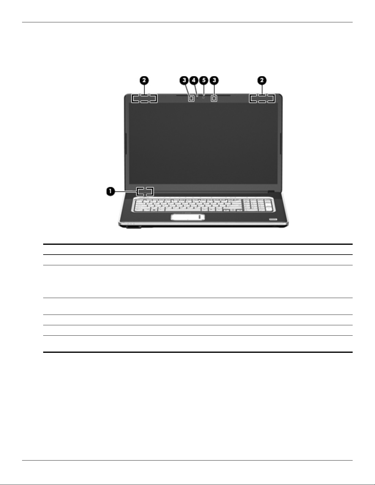
Display components
Item Component Description
(1) Internal display switch Turns off the display if the display is closed while the computer is on.
(2) Wireless antennas (2) Send and receive wireless signals to communicate with WLANs.
✎
The antennas are not visible from the outside of the computer.
For optimal transmission, keep the areas immediately around the
antennas free from obstructions.
(3) Internal digital dual-array
microphones (2)
Record sound.
(4) Webcam light On: The webcam is in use.
(5) Webcam Records audio and video and captures still photographs.
✎
To see wireless regulatory notices, refer to the section of the Regulatory, Safety and Environmental Notices that applies
to your country or region. These notices are located in Help and Support.
External component identification
Maintenance and Service Guide 2–3
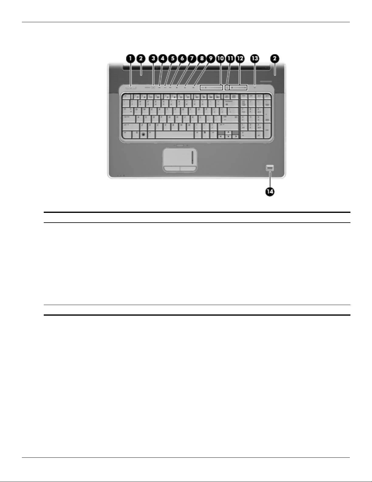
Buttons, speakers, and fingerprint reader
Item Component Description
(1) Power button* ■ When the computer is off, press the button to turn on the computer.
■ When the computer is on, briefly press the button to initiate Sleep.
■ When the computer is in the Sleep state, briefly press the button to
exit Sleep.
■ When the computer is in Hibernation, briefly press the button to
exit Hibernation.
If the computer has stopped responding and Windows shutdown procedures
are ineffective, press and hold the power button for at least 5 seconds to turn
off the computer.
To learn more about your power settings, select Start > Control Panel >
System and Security > Power Options.
(2) Speakers (2) Produce sound.
(Continued)

2–4 Maintenance and Service Guide
External component identification
(3) Media button Starts the MediaSmart program.
(4) Previous/rewind button ■ Plays the previous track or chapter when the button is pressed once.
■ Rewinds media when the button is pressed in combination with the fn key.
(5) Play/pause button Plays or pauses media.
(6) Next/fast forward button ■ Plays the next track or chapter when the button is pressed once.
■ Fast forwards media when pressed in combination with the fn key.
(7) Stop button Stops playback.
(8) Optical drive button Releases the media tray.
(9) Volume mute button Mutes and restores speaker sound.
(10) Volume scroll zone Adjusts speaker volume. To decrease volume, slide your finger to the left, or
press and hold the minus (-) sign. You can also tap the minus sign. To
increase volume, slide your finger to the right, or press and hold the plus (+)
sign. You can also tap the plus sign.
(11) Treble/bass button Press the button to alternate between the treble and bass functions.
(12) Treble or bass scroll zone Adjusts treble or bass level in the audio. (Select treble or bass by pressing the
treble/bass button.) To decrease the treble/bass level, slide your finger to the
left, or press and hold the minus (-) sign. You can also tap the minus sign. To
increase the treble/bass level, slide your finger to the right, or press and hold
the plus (+) sign. You can also tap the plus sign.
(13) Wireless button Turns the wireless feature on or off but does not establish a wireless
connection.
✎
You must set up or access a wireless network in order to establish a
wireless connection.
(14) Fingerprint reader Allows a fingerprint logon to Windows, instead of a password logon.
*This table describes factory settings. For information about changing factory settings, refer to the user guides located in
Help and Support.
Item Component Description
External component identification
Maintenance and Service Guide 2–5
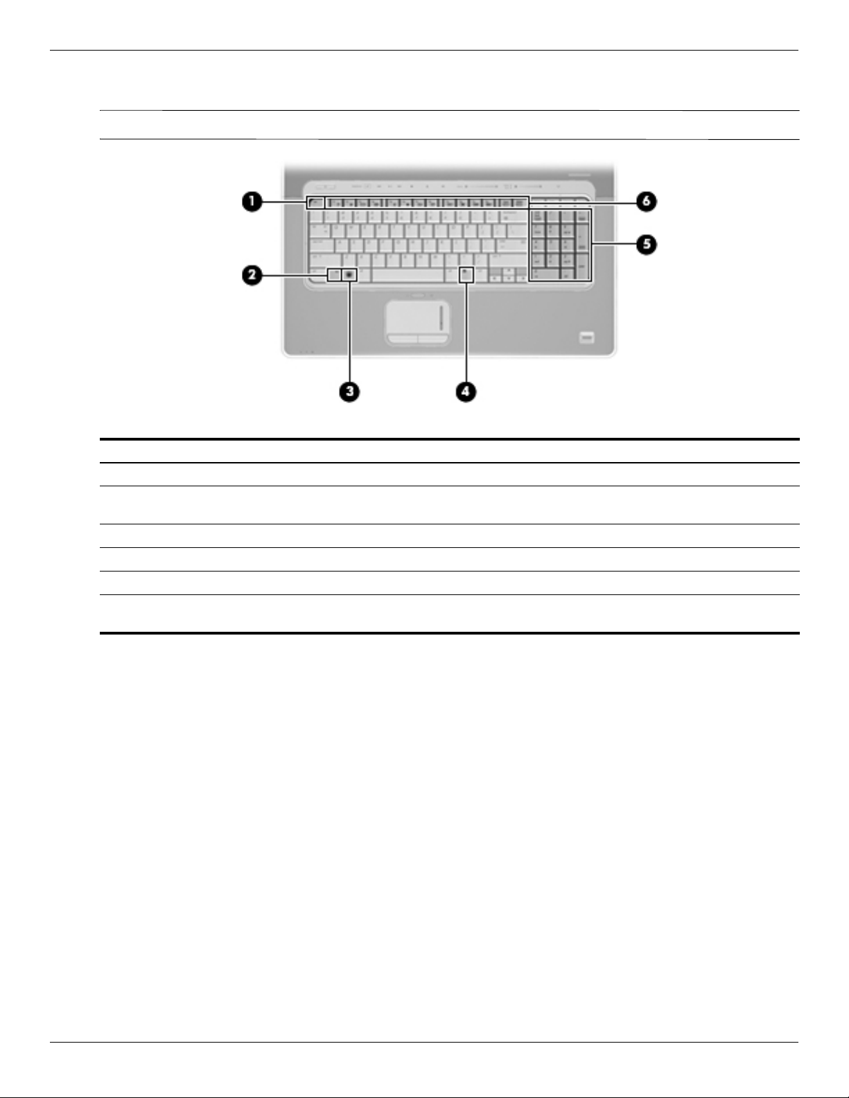
Keys
✎
Your computer may look slightly different from the illustration in this section.
Item Component Description
(1) esc key Displays system information when pressed in combination with the fn key.
(2) fn key Executes frequently used system functions when pressed in combination with
a function key or the esc key.
(3) Windows logo key Displays the Windows Start menu.
(4) Windows applications key Displays a shortcut menu for items beneath the pointer.
(5) Integrated numeric keypad keys Can be used like the keys on an external numeric keypad.
(6) Function keys Execute frequently used system functions when pressed in combination with
the fn key.
2–6 Maintenance and Service Guide
External component identification
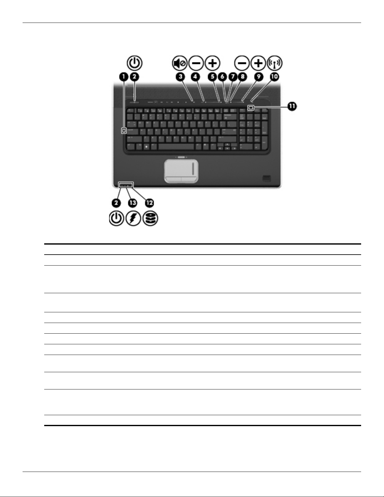
Lights
Item Component Description
(1) Caps lock light On: Caps lock is on.
(2) Power lights (2)* ■ On: The computer is on.
■ Blinking: The computer is in the Sleep state.
■ Off: The computer is off or in Hibernation.
(3) Volume mute light ■ White: Computer sound is on.
■ Amber: Computer sound is off.
(4) Volume down light On: The volume scroll zone is being used to decrease speaker volume.
(5) Volume up light On: The volume scroll zone is being used to increase speaker volume.
(6) Treble light On: The treble function is on.
(7) Bass light On: The bass function is on.
(8) Treble/bass down light On: The treble or bass scroll zone is being used to decrease the level of treble
or bass in the audio.
(9) Treble/bass up light On: The treble or bass scroll zone is being used to increase the level of treble
or bass in the audio.
(10) Wireless light ■ Blue: An integrated wireless device, such as a wireless local area network
(WLAN) device and/or a Bluetooth device, is on.
■ Amber: All wireless devices are off.
(11) Num lock light On: Num lock is on or the embedded numeric keypad is enabled.
(Continued)

External component identification
Maintenance and Service Guide 2–7
(12) Drive light ■ Blinking: The hard drive or optical drive is being accessed.
■ Amber: HP ProtectSmart Hard Drive Protection has temporarily parked the
internal hard drive.
(13) Battery light ■ On: A battery is charging.
■ Blinking: A battery that is the only available power source has reached a
low battery level or a critical battery level. When the battery reaches a
critical battery level, the battery light begins blinking rapidly.
■ Off: If the computer is plugged into an external power source, the light is
turned off when all batteries in the computer are fully charged. If the
computer is not plugged into an external power source, the light stays off
until the battery reaches a low battery level.
*The 2 power lights display the same information. The light on the power button is visible only when the computer is open.
The power light on the front of the computer is visible whether the computer is open or closed.
Item Component Description
2–8 Maintenance and Service Guide
External component identification
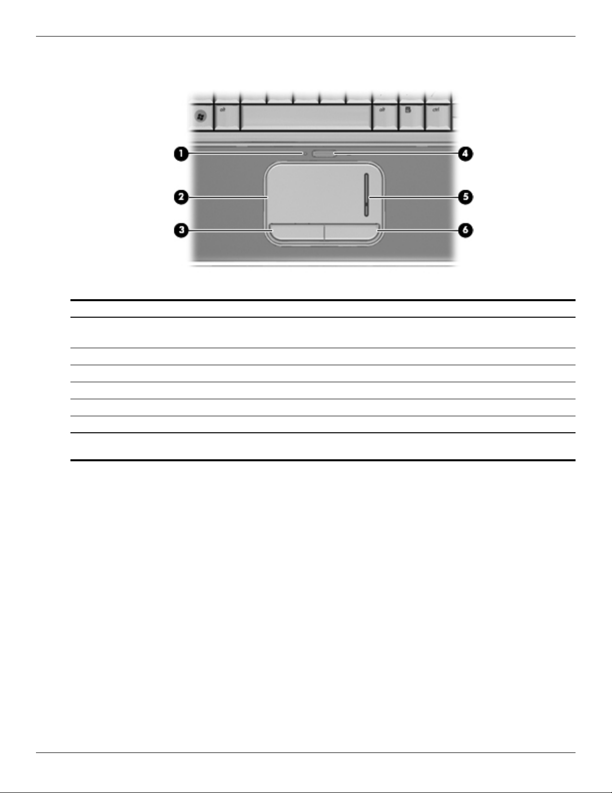
Pointing devices
Item Component Description
(1) TouchPad light ■ White: TouchPad is enabled.
■ Amber: TouchPad is disabled.
(2) TouchPad* Moves the pointer and selects or activates items on the screen.
(3) Left TouchPad button* Functions like the left button on an external mouse.
(4) TouchPad on/off button Enables/disables the TouchPad.
(5) TouchPad scroll zone Scrolls up or down.
(6) Right TouchPad button* Functions like the right button on an external mouse.
*This table describes factory settings. To view or change pointing device preferences, select Start > Devices and Printers.
Then, right-click the device representing your computer, and select Mouse settings.

External component identification
Maintenance and Service Guide 2–9
Front components
Item Component Description
(1) Digital Media Slot Supports the following optional digital card formats:
■ Memory Stick (MS)
■ Memory Stick Pro (MSP)
■ MultiMediaCard (MMC)
■ Secure Digital (SD) Memory Card
■ xD-Picture Card (XD)
(2) Digital Media Slot light On: A digital card is being accessed.
(3) Consumer infrared lens Receives a signal from the remote control (select models only).
2–10 Maintenance and Service Guide
External component identification
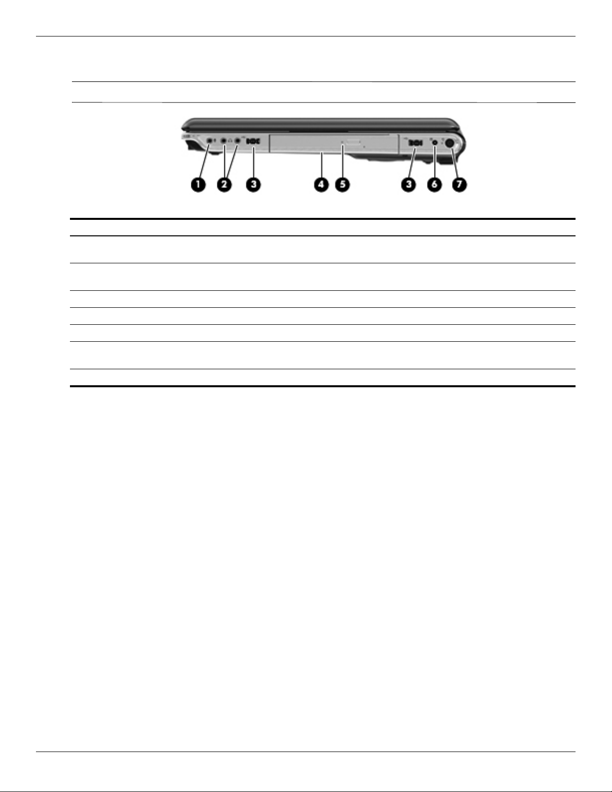
Right-side components
✎
Your computer may look slightly different from the illustration in this section.
Item Component Description
(1) Audio-in (microphone) jack Connects an optional computer headset microphone, stereo array
microphone, or monaural microphone.
(2) Audio-out (headphone) jacks (2) Produce sound when connected to optional powered stereo speakers,
headphones, ear buds, headsets, or television audio.
(3) USB ports (2) Connect optional USB devices.
(4) Optical drive Reads optical discs and, on select models, also writes to optical discs.
(5) Optical drive light Blinking: The optical drive is being accessed.
(6) TV antenna/cable jack (select
models only)
Connects an optional TV antenna or an optional digital cable device that
receives standard or high-definition TV broadcasts.
(7) Power connector Connects an AC adapter.
External component identification
Maintenance and Service Guide 2–11
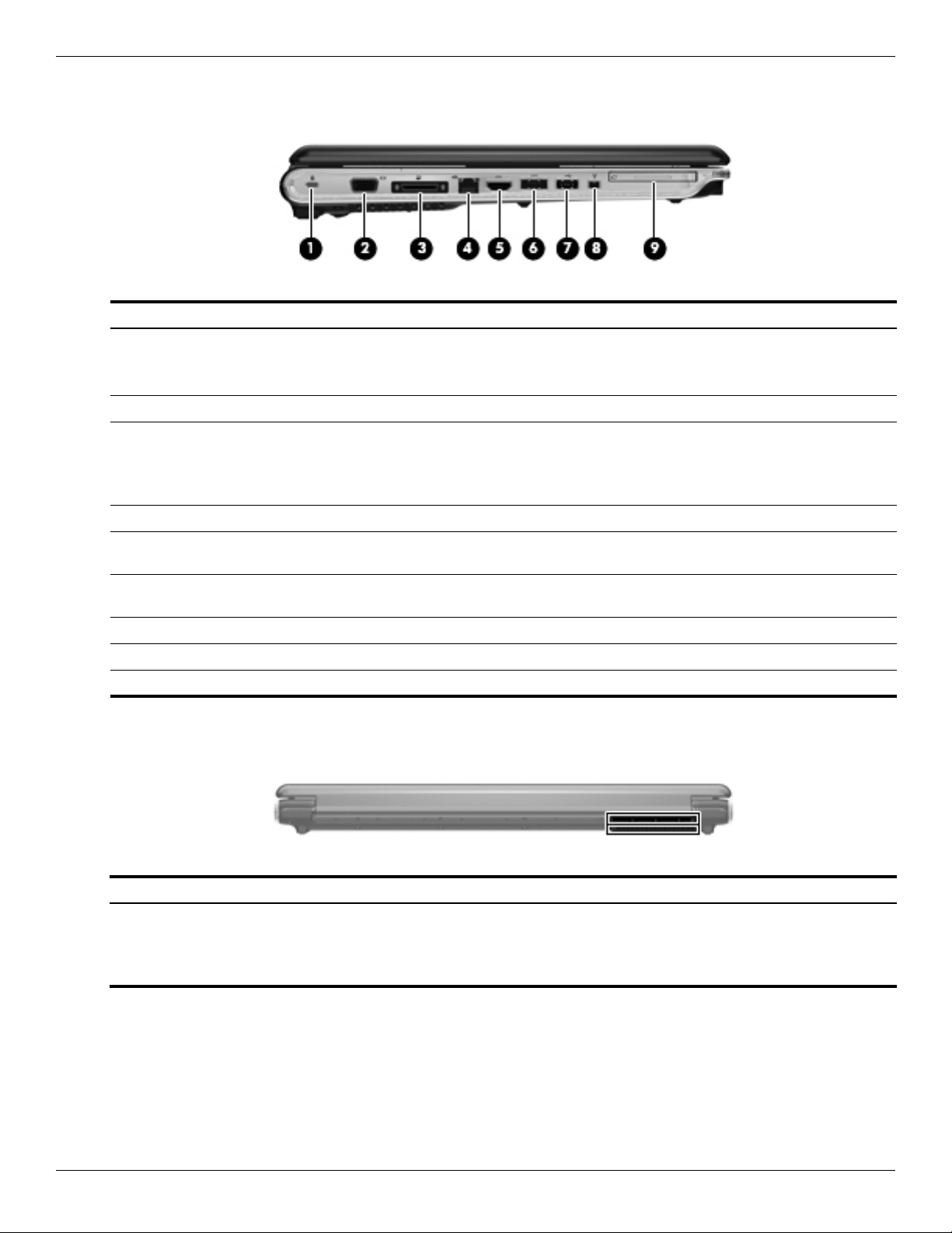
Left-side components
Rear component
Item Component Description
(1) Security cable slot Attaches an optional security cable to the computer.
✎
The security cable is designed to act as a deterrent, but it may not
prevent the computer from being mishandled or stolen.
(2) External monitor port Connects an external VGA monitor or projector.
(3) Expansion port 3 Connects the computer to an optional docking device or optional expansion
product.
✎
The computer has only one expansion port. The term expansion port 3
describes the type of expansion port.
(4) RJ-45 (network) jack Connects a network cable.
(5) HDMI port Connects an optional video or audio device, such as a high-definition
television, or any compatible digital or audio component.
(6) eSATA/USB port Connects an optional high-performance eSATA component, such as an
eSATA external hard drive, or connects an optional USB device.
(7) USB port Connects an optional USB device.
(8) 1394 port Connects an optional IEEE 1394 or 1394a device, such as a camcorder.
(9) ExpressCard slot Supports optional ExpressCards.
Component Description
Vent Enables airflow to cool internal components.
✎
The computer fan starts up automatically to cool internal components
and prevent overheating. It is normal for the internal fan to cycle on and
off during routine operation.
2–12 Maintenance and Service Guide
External component identification
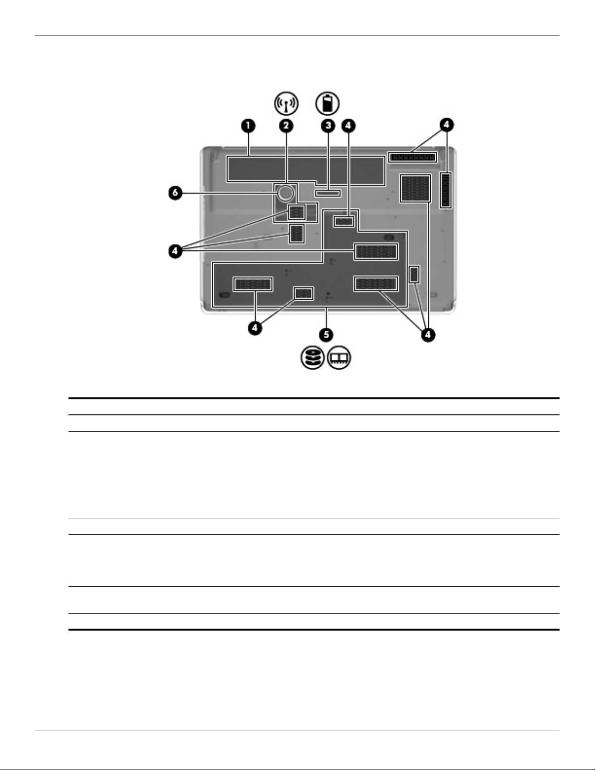
Bottom components
Item Component Description
(1) Battery bay Holds the battery.
(2) Mini Card compartment Holds the WLAN module.
Ä
To prevent an unresponsive system, replace the wireless module only
with a wireless module authorized for use in the computer by the
governmental agency that regulates wireless devices in your country or
region. If you replace the module and then receive a warning message,
remove the module to restore computer functionality, and then contact
technical support through Help and Support.
(3) Battery release latch Releases the battery from the battery bay.
(4) Vents (11) Enable airflow to cool internal components.
✎
The computer fan starts up automatically to cool internal components
and prevent overheating. It is normal for the internal fan to cycle on and
off during routine operation.
(5) Hard drive bay Holds 1 or 2 hard drives (depending on the model), the TV tuner module
(select models only), and the 2 memory module slots.
(6) Subwoofer Contains the subwoofer speaker.
Maintenance and Service Guide 3–1
3
Illustrated parts catalog
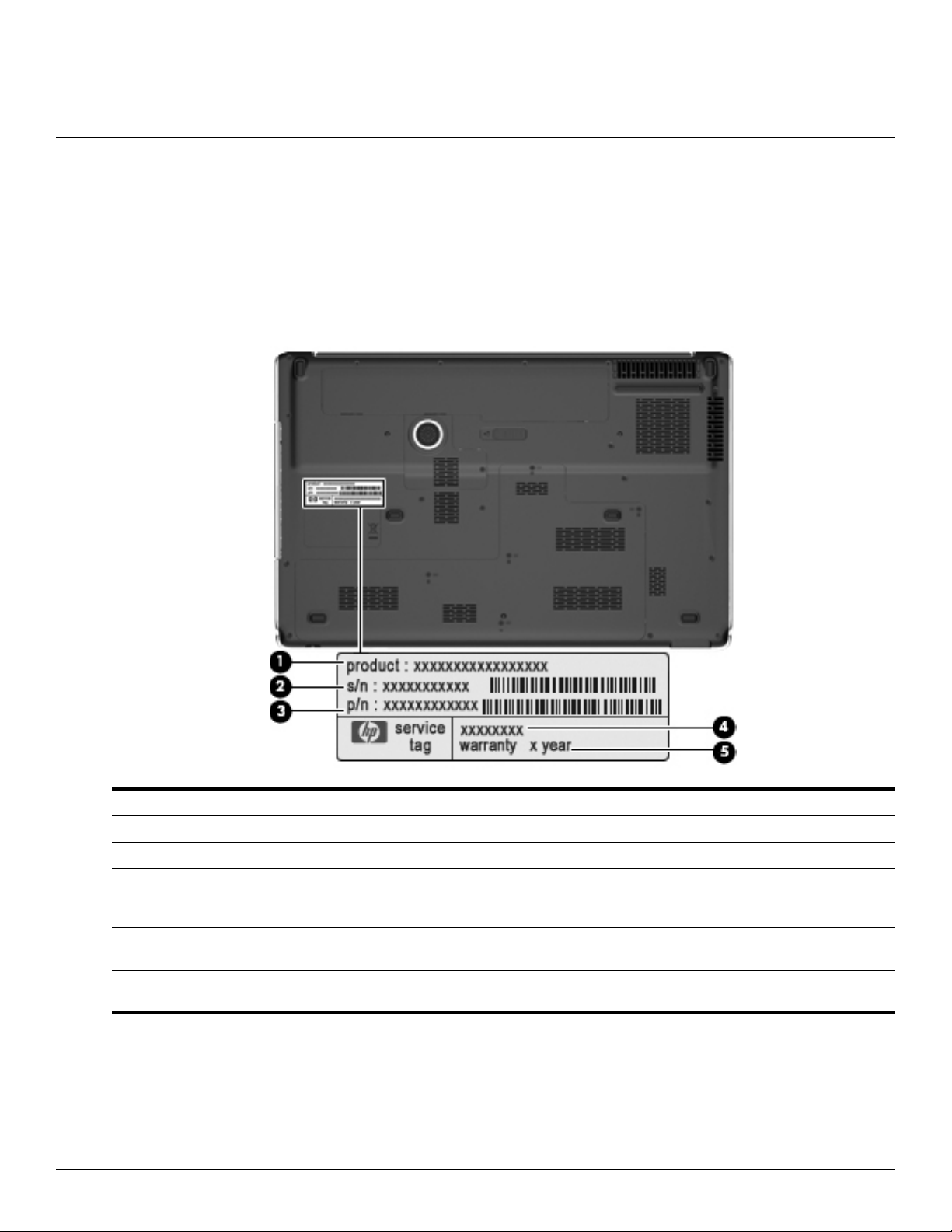
Service tag
When ordering parts or requesting information, provide the computer serial number and model number provided on
the service tag.
Item Component Description
(1) Product name This is the product name affixed to the front of the computer.
(2) Serial number (s/n) This is an alphanumeric identifier that is unique to each product.
(3) Part number/Product number (p/n) This number provides specific information about the product’s
hardware components. The part number helps a service
technician determine what components and parts are needed.
(4) Model description This is the alphanumeric identifier used to locate documents,
drivers, and support for the computer.
(5) Warranty period This number describes the duration (in years) of the warranty
period for the computer.
3–2 Maintenance and Service Guide
Illustrated parts catalog
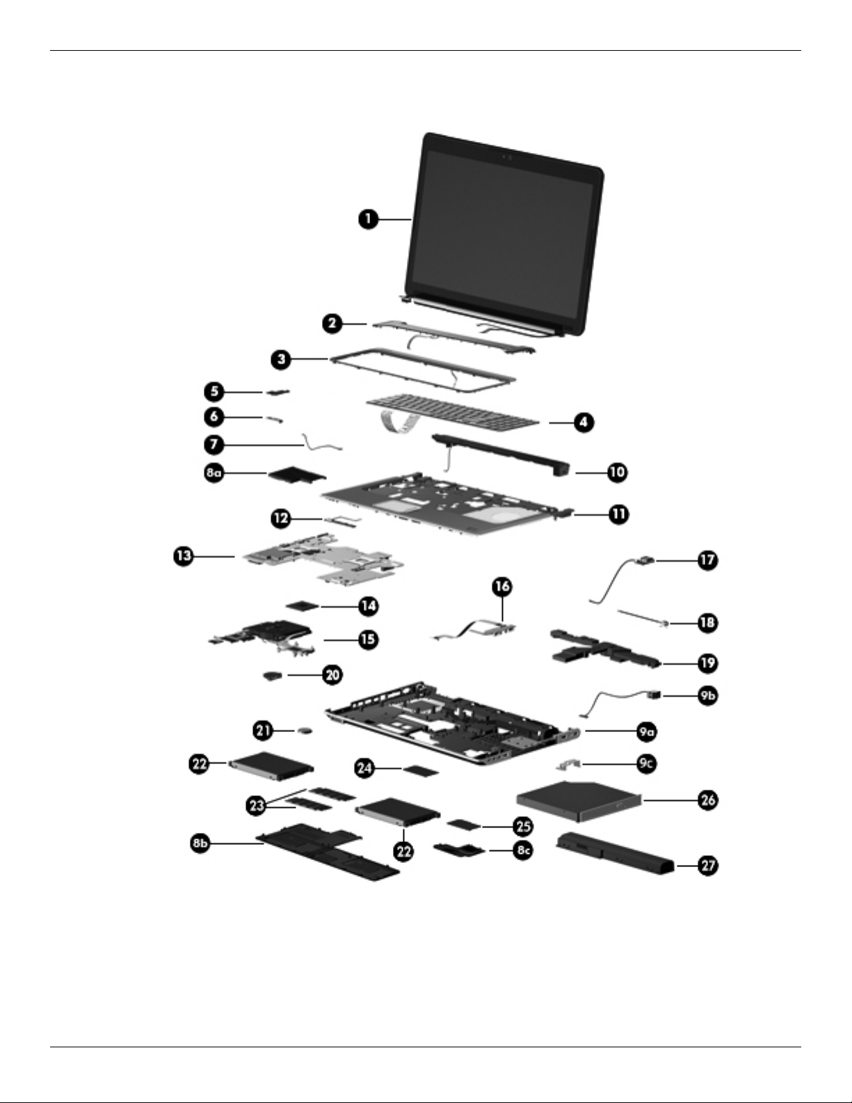
Computer major components

Illustrated parts catalog
Maintenance and Service Guide 3–3
Item Description Spare part number
(1) 18.4-inch, AntiGlare, high-definition, dual-lamp display assembly (includes 2 WLAN
antenna transceivers and cables, webcam, microphones, and logo)
577001-001
✎
See “Display assembly components” on page 3-6 for information on display assembly spare part numbers.
(2) Switch cover 577008-001
(3) Keyboard cover (includes LED board and cable) 577009-001
(4) Keyboard (includes cable):
For use in Belgium 578916-A41
For use in Denmark, Finland, and Norway 578916-DH1
For use in France 578916-051
For use in French Canada 578917-121
For use in Germany 578916-041
For use in Italy 578916-061
For use in the Netherlands 578916-B31
For use in Portugal 578916-131
For use in Russia 578916-251
For use in Saudi Arabia 578916-171
For use in South Korea 578916-AD1
For use in Spain 578916-071
For use in Switzerland 578916-111
For use in Taiwan 578916-AB1
For use in Turkey 578916-141
For use in the United Kingdom 578916-031
For use in the United States 578916-001
(5) Power button board (includes cable) 580987-001
(6) Bluetooth module 577000-001
✎
The Bluetooth module spare part kit does not include a Bluetooth module cable. The Bluetooth module cable
is available using spare part number 537921-001.
(7) Bluetooth module cable 537921-001
Plastics Kit, includes: 580404-001
(8a) ExpressCard slot bezel
(8b) Mass storage device cover
(8c) WLAN module compartment cover
✎
See “Plastics Kit” on page 3-8 for more Plastics Kit spare part information.
(9a) Base enclosure, includes: 577005-001
(9b) Power connector cable
(9c) Power connector cable bracket
7 rubber feet (not illustrated)
Rubber Feet Kit (not illustrated, includes 7 rubber feet) 496889-001
(Continued)

3–4 Maintenance and Service Guide
Illustrated parts catalog
(10) Speaker assembly 496887-001
(11) Top cover (includes fingerprint reader board, fingerprint reader board cable, TouchPad,
and TouchPad cables)
577007-001
(12) TouchPad on/off button board (includes cable) 580986-001
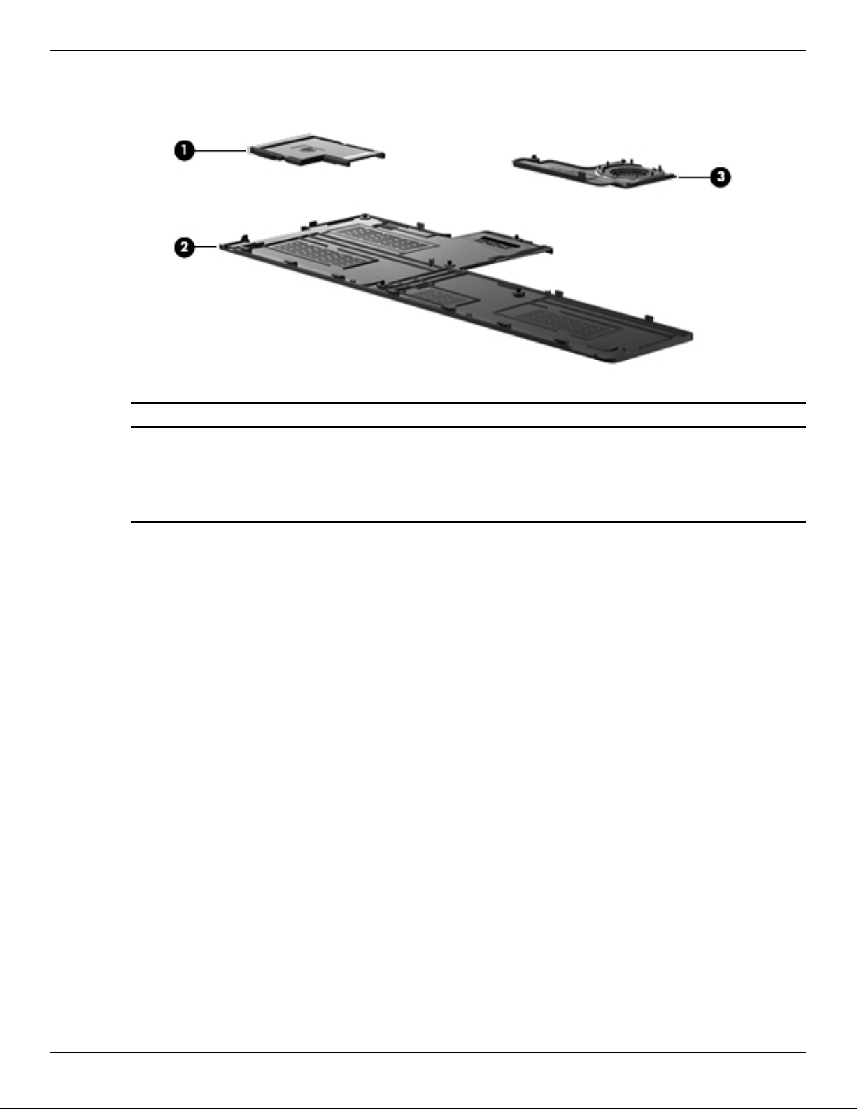
(13) System board (includes 1024 MB of graphics subsystem memory and replacement
thermal material)
573758-001
(14) Processor (includes replacement thermal material):
Intel Core i7-820QM 1.73-GHz processor (SC turbo up to 3.06 GHz) 583053-001
Intel Core i7-720QM 1.60-GHz processor (SC turbo up to 2.80 GHz) 586170-001
(15) Fan/heat sink assembly (includes replacement thermal material) 579989-001
(16) Audio/infrared board (includes cable) 580988-001
(17) USB board (includes cable) 580989-001
Cable Kit, includes: 496891-001
(18) TV tuner module cable
(19) Subwoofer (includes 3 mounting grommets) 577010-001
(20) Fan 514290-001
(21) RTC battery 449729-001
(22) Mass storage device:
Hard drive (includes left and right brackets, Mylar sleeve, connector, and 4 isolators):
■ 500-GB, 7200-rpm 577607-001
■ 500-GB, 5400-rpm 501911-001
■ 320-GB, 7200-rpm 507553-001
■ 320-GB, 5400-rpm 503485-001
■ 250-GB, 7200-rpm 507552-001
■ 250-GB, 5400-rpm 503484-001
Solid-state drive (includes left and right brackets, Mylar sleeve, connector, and 4 isolators):
■ 256-GB 577609-001
■ 128-GB 577608-001
Mass Storage Device Hardware Kit (not illustrated, includes left and right brackets,
Mylar sleeve, connector, and 4 isolators)
483862-001
(23) Memory modules (1066-MHz, DDR3):
4096-MB 577606-001
2048-MB 577605-001
1024-MB 577604-001
(Continued)
Item Description Spare part number

Illustrated parts catalog
Maintenance and Service Guide 3–5
(24) WLAN module:
Intel WiFi Link 5100 802.11 a/g/n WLAN module for use in Andorra, Antigua and Barbuda,
Argentina, Aruba, Australia, Austria, Azerbaijan, the Bahamas, Bahrain, Barbados,
Belgium, Bermuda, Bolivia, Bosnia, Brazil, Brunei, Bulgaria, Canada, the Cayman Islands,
Chile, Colombia, Costa Rica, Croatia, Cyprus, the Czech Republic, Denmark,
the Dominican Republic, Ecuador, Egypt, El Salvador, Estonia, Finland, France,
French Guiana, Georgia, Germany, Ghana, Greece, Guadeloupe, Guam, Guatemala,
Haiti, Herzegovina, Honduras, Hong Kong, Hungary, Iceland, India, Indonesia, Ireland,
Israel, Italy, the Ivory Coast, Jamaica, Japan, Jordan, Kenya, Kuwait, Kyrgyzstan, Latvia,
Lebanon, Liechtenstein, Lithuania, Luxembourg, Malawi, Malaysia, Malta, Martinique,
Mauritius, Mexico, Monaco, Montenegro, Morocco, the Nether Antilles, the Netherlands,
New Zealand, Nicaragua, Nigeria, Norway, Oman, Pakistan, Panama, Paraguay,
the People's Republic of China, Peru, the Philippines, Poland, Portugal, Puerto Rico,
Qatar, Romania, San Marino, Saudi Arabia, Senegal, Singapore, Slovakia, Slovenia,
South Africa, South Korea, Spain, Sri Lanka, Sweden, Switzerland, Taiwan, Tanzania,
Thailand, Trinidad and Tobago, Turkey, the United Arab Emirates, the United Kingdom,
the United States, Uruguay, the U.S. Virgin Islands, Venezuela, and Vietnam
572507-001
Intel WiFi Link 5100 802.11 a/b/g WLAN module for use in Andorra, Antigua and Barbuda,
Argentina, Aruba, Australia, Austria, Azerbaijan, the Bahamas, Bahrain, Barbados,
Belgium, Bermuda, Bolivia, Bosnia, Brazil, Brunei, Bulgaria, Canada, the Cayman Islands,
Chile, Colombia, Costa Rica, Croatia, Cyprus, the Czech Republic, Denmark,
the Dominican Republic, Ecuador, Egypt, El Salvador, Estonia, Finland, France,
French Guiana, Georgia, Germany, Ghana, Greece, Guadeloupe, Guam, Guatemala,
Haiti, Herzegovina, Honduras, Hong Kong, Hungary, Iceland, India, Indonesia, Ireland,
Israel, Italy, the Ivory Coast, Jamaica, Japan, Jordan, Kenya, Kuwait, Kyrgyzstan, Latvia,
Lebanon, Liechtenstein, Lithuania, Luxembourg, Malawi, Malaysia, Malta, Martinique,
Mauritius, Mexico, Monaco, Montenegro, Morocco, the Nether Antilles, the Netherlands,
New Zealand, Nicaragua, Nigeria, Norway, Oman, Pakistan, Panama, Paraguay,
the People's Republic of China, Peru, the Philippines, Poland, Portugal, Puerto Rico,
Qatar, Romania, San Marino, Saudi Arabia, Senegal, Singapore, Slovakia, Slovenia,
South Africa, South Korea, Spain, Sri Lanka, Sweden, Switzerland, Taiwan, Tanzania,
Thailand, Trinidad and Tobago, Turkey, the United Arab Emirates, the United Kingdom,
the United States, Uruguay, the U.S. Virgin Islands, Venezuela, and Vietnam
572508-001
(25) TV tuner module:
✎
The TV tuner module spare part kit does not include a TV tuner module cable. The TV tuner module cable is
included in the Cable Kit, spare part number 496891-001.
DVB-T TV tuner module 482899-003
DVB-T/ANG TV tuner module 482899-002
NTSC/ATSC/ANG TV tuner module 482899-001
TV tuner external antenna cable (not illustrated):
With F-PAL jack 482900-002
With PAL jack 482900-001
(26) Optical drive (includes optical drive bezel and bracket):
Blu-ray ROM with LightScribe DVD±RW SuperMulti DL Drive 503488-001
Blu-ray ROM DVD±RW SuperMulti DL Drive 503487-001
(27) Battery:
8-cell, 73-Wh Li-ion battery 480385-001
4-cell, 63-Wh Li-ion battery 516916-001
Item Description Spare part number
3–6 Maintenance and Service Guide
Illustrated parts catalog
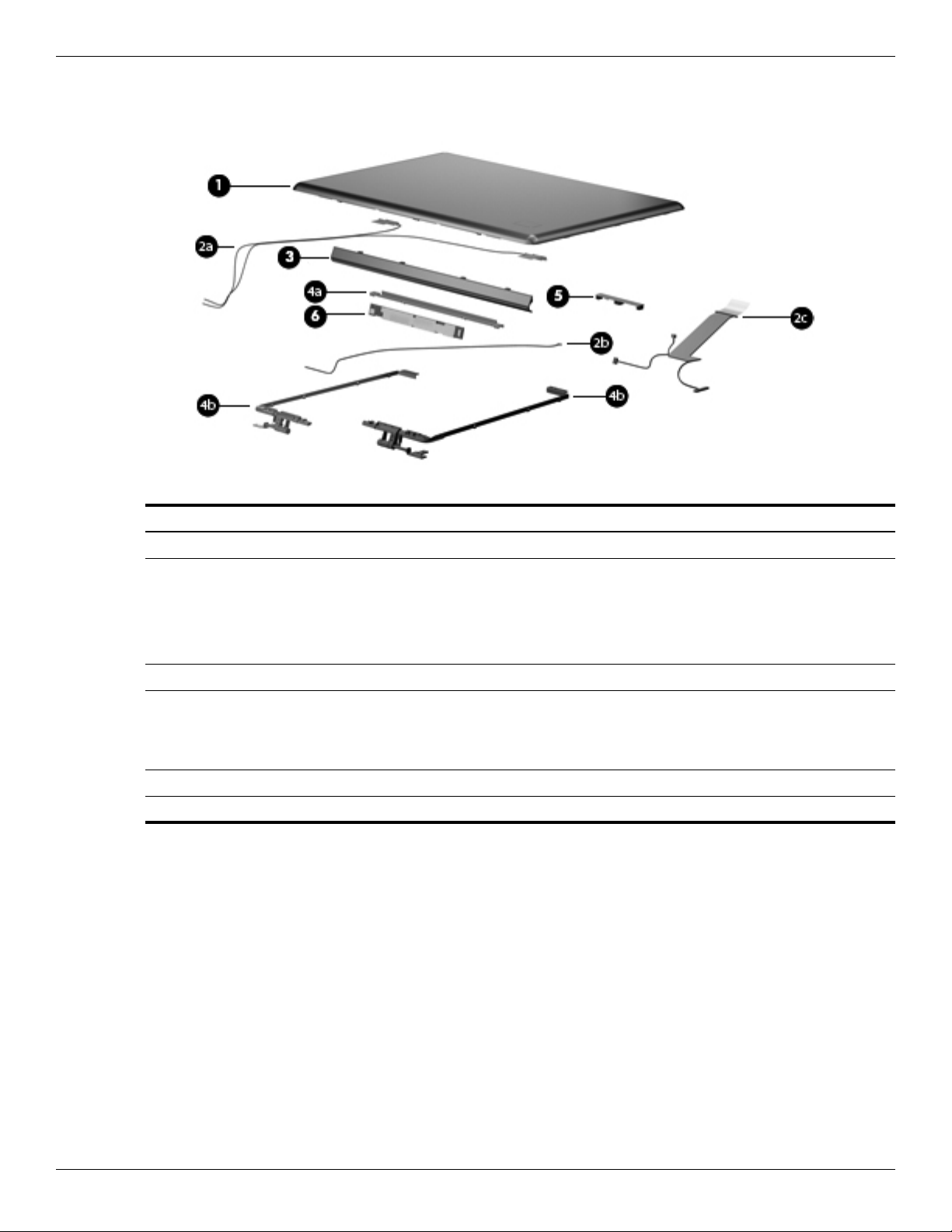
Display assembly components
Item Description Spare part number
(1) Display enclosure 577003-001
Display Cable Kit, includes: 496876-001
(2a) Wireless antenna transceivers and cables
(2b) Webcam/microphone module cable
(2c) Display panel cable
(3) Display hinge cover 577004-001
Display Hinge Kit, includes: 496874-001
(4a) Display hinge bracket
(4b) Display left and right hinges
(5) Webcam/microphone module 499242-001
(6) Display inverter 498324-001
Illustrated parts catalog
Maintenance and Service Guide 3–7
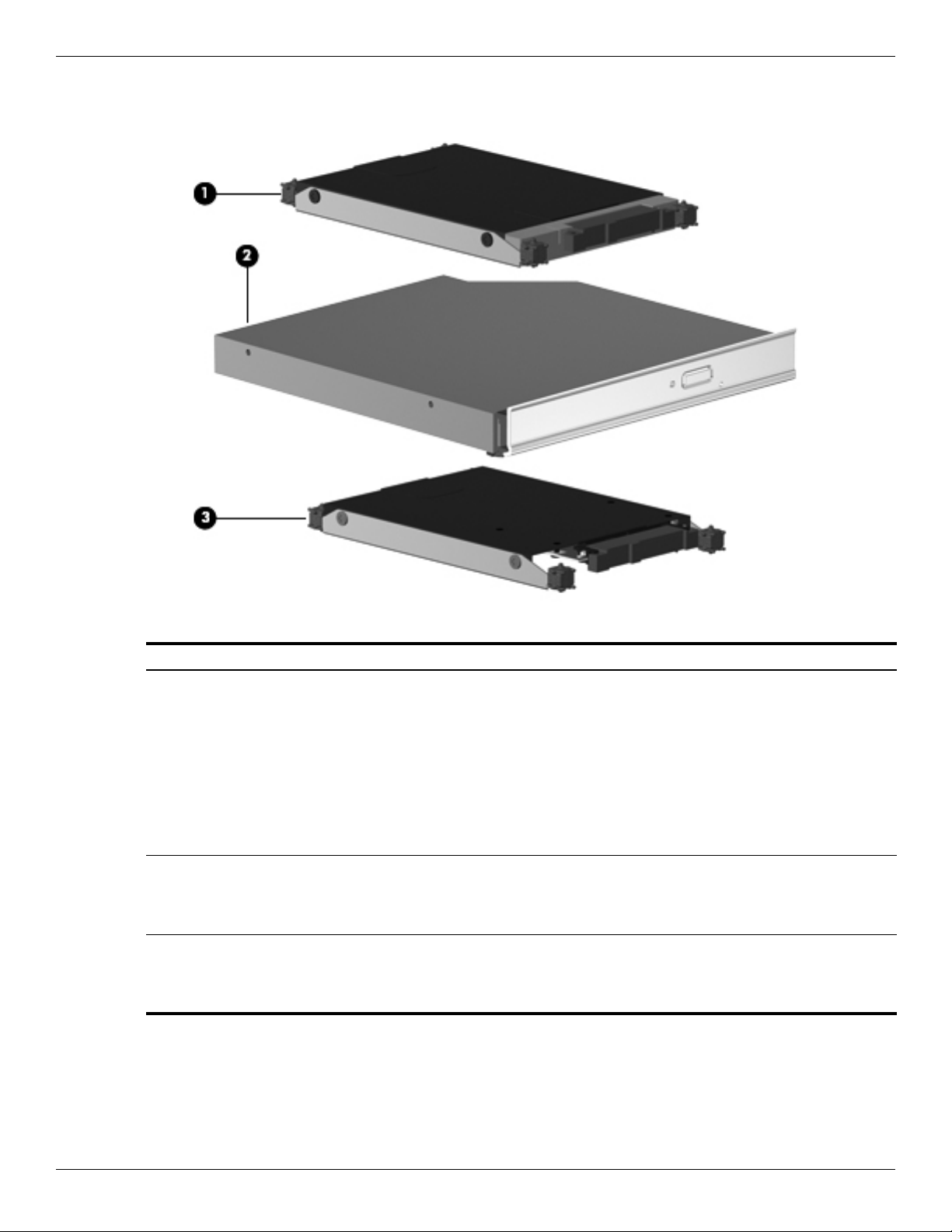
Mass storage devices
Item Description Spare part number
(1) Hard drive (includes left and right brackets, Mylar sleeve, connector, and 4 isolators):
500-GB, 7200-rpm 577607-001
500-GB, 5400-rpm 501911-001
320-GB, 7200-rpm 507553-001
320-GB, 5400-rpm 503485-001
250-GB, 7200-rpm 507552-001
250-GB, 5400-rpm 503484-001
(2) Optical drive (includes optical drive bezel and bracket):
Blu-ray ROM with LightScribe DVD±RW SuperMulti DL Drive 503488-001
Blu-ray ROM DVD±RW SuperMulti DL Drive 503487-001
(3) Solid-state drive (includes left and right brackets, Mylar sleeve, connector, and 4 isolators):
256-GB 577609-001
128-GB 577608-001
3–8 Maintenance and Service Guide
Illustrated parts catalog
Plastics Kit
Item Description Spare part number
Plastics Kit: 580404-001
(1) ExpressCard slot bezel
(2) Mass storage device cover (includes five captive screws, secured by C-clips)
(3) WLAN module compartment cover (includes one captive screw, secured by a C-clip)

Illustrated parts catalog
Maintenance and Service Guide 3–9
Miscellaneous parts
Description Spare part number
120-W AC adapter 463953-001
Power cord:
For use in Argentina 490371-D01
For use in Australia 490371-011
For use in Brazil 490371-201
For use in Denmark 490371-081
For use in Europe, the Middle East, and Africa 490371-021
For use in India 490371-D61
For use in Italy 490371-061
For use in the People’s Republic of China 490371-AA1
For use in South Africa 490371-AR1
For use in South Korea 490371-AD1
For use in Taiwan 490371-AB1
For use in the United Kingdom and Singapore 490371-031
For use in Canada, Mexico, and the United States 490371-001
Remote control:
Full-function remote control with teletext 465541-001
Full-function remote control without teletext 465540-001
Screw Kit, includes:
■ Phillips PM3.0×4.0 screw
■ Phillips PM2.5×7.0 screw
■ Phillips PM2.5×6.0 captive screw
■ Phillips PM2.5×5.0 broadhead screw
■ Phillips PM2.5×5.0 captive screw
■ Phillips PM2.5×4.0 screw
■ Phillips PM2.0×11.0 captive screw
■ Phillips PM2.0×4.0 screw
496890-001
Wired headset with volume control 371693-001
Loading...