


 Loading...
H
High-Performance IR Emitter
and IR PIN Photodiode in
Subminiature SMT Package
Technical Data
Features
•Subminiature Flat Top and Dome Package
Size – 2x2 mm
•IR Emitter
875 nm TS AlGaAs Intensity – 17 mW/sr Speed – 40 ns
•Wide Range of Drive
Currents
500 μA to 500 mA
•IR Detector
PIN Photodiode High Sensitivity Speed – 7.5 ns
•Flexible Lead Configurations
Surface Mount or Through Hole
Applications
•Short Distance IR Links
•IrDA Compatible
•Small Handheld Devices
Pagers
Industrial Handhelds
•Diffuse LANs
•Wireless Audio
Description
Flat Top Package
The HSDL-4400 Series of flat top IR emitters use an untinted, nondiffused, truncated lens to provide a wide radiation pattern that is useful for short distance communication where alignment of the emitter and detector is not critical. The HSDL-5400 Series of flat top IR detectors uses the same truncated lens design as the HSDL-4400 Series of IR emitters with the added feature of a black tint that acts as an optical filter to reduce the effects of ambient light, such as sun, incandescent and fluorescent light from interfering with the IR signal.
Dome Package
The HSDL-4420 Series of dome IR emitters uses an untinted, nondiffused lens to provide a 24 degree viewing angle with high on-axis intensity. The HSDL-5420 Series of IR detectors uses the same lens design as the HSDL4420 IR emitter and optical filter used in the HSDL-5400 IR detector.
HSDL-44XX IR Emitter
Series
HSDL-54XX IR Detector
Series
Lead Configuration
All of these devices are made by encapsulating LED and PIN photodiode chips on axial lead frames to form molded epoxy subminiature packages. A variety of lead configurations is available and includes: surface mount gull wing, yoke lead, or Z-bend and through hole lead bends at 2.54 mm (0.100 inch) center spacing.
Technology
The subminiature solid state emitters utilize a highly optimized LED material, transparent substrate aluminum gallium arsenide, TS AlGaAs. This material has a very high radiant efficiency, capable of producing high light output over a wide range of drive currents and temperature.
4-68 |
5964-9018E |

Device Selection Guide
IR Emitters
Part Number |
Device Description[1] |
Device Outline Drawing |
HSDL-4400 |
LED, Flat Top, 110 deg |
A |
|
|
|
HSDL-4420 |
LED, Dome, 24 deg |
B |
|
|
|
IR Detectors |
|
|
|
|
|
Part Number |
Device Description[1] |
Device Outline Drawing |
HSDL-5400 |
PIN Photodiode, Flat Top, 110 deg |
C |
|
|
|
HSDL-5420 |
PIN Photodiode, Dome, 28 deg |
D |
Package Configuration Options
|
|
|
|
|
Package Outline |
Option Code |
Package Configuration Description |
Drawing |
|||
|
|
|
|
|
|
011 |
Gull Wing Lead, Tape and Reel[2] |
|
E, J, M |
||
021 |
Yoke Lead, Tape and Reel[2] |
Surface |
F, K, M |
||
031 |
Z-Bend, Tape and Reel[2] |
|
Mount Lead |
G, L, M |
|
1L1 |
2.54 mm (0.100 in) |
|
Long Leads; |
Thru Hole |
H |
|
Center Lead Spacing |
|
10.4 mm (0.410 in) |
Lead |
|
|
|
|
|
|
|
1S1 |
|
|
Short Leads; |
|
I |
|
|
|
|||
|
|
|
3.7 mm (0.145 in) |
|
|
|
|
|
|
|
|
No Option |
Straight Leads[3] |
|
Prototyping |
A, B, C, D |
|
Notes:
1.IR Emitters have untinted, nondiffused lenses and IR Detectors have black tinted, nondiffused lenses.
2.Emitters and detectors are supplied in 12 mm embossed tape on 178 mm (7 inch) diameter reels, with 1500 units per reel. Minimum order quantity and order increment are in quantity of reels only.
3.Emitters and detectors are supplied in bulk form in bags of 50 units.
4-69

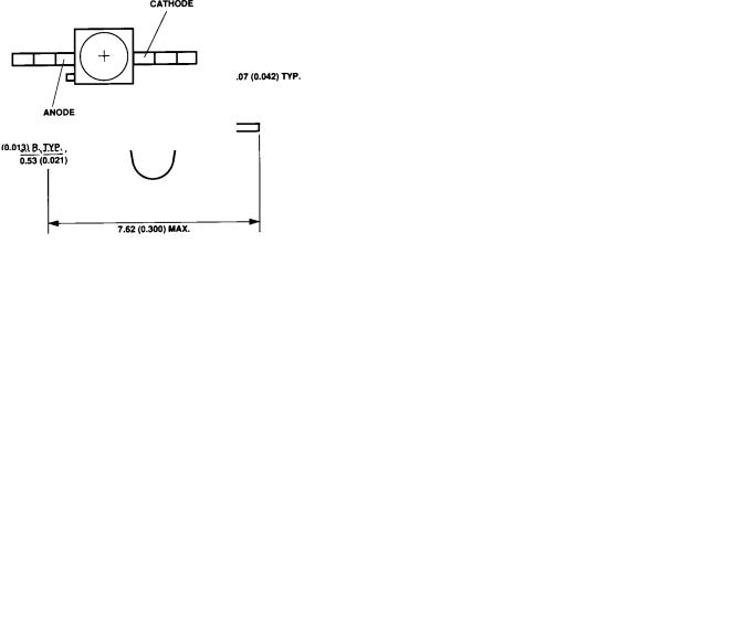
Package Dimensions |
|
|
|
|
|
|
|
|
1.40 |
(0.055) |
|
|
|
||||||||||||||||||||
(A) Flat Top Emitters |
|
|
|
|
|
|
|
|
|
|
|
||||||||||||||||||||||
|
|
|
|
|
|
0.50 (0.020) REF. |
(0.065) |
|
|
|
|||||||||||||||||||||||
|
|
|
|
|
|
|
|
|
|
|
|
|
|
|
|
|
|
|
|
|
|
|
|
|
|
|
1.65 |
|
|
|
|||
|
|
|
|
|
|
|
|
|
|
|
|
|
|
|
|
|
|
|
|
|
|
|
|
|
|
|
|
|
|
|
|
NOTE 3 |
|
|
|
|
|
|
|
|
|
|
|
|
|
|
|
|
|
|
|
|
|
|
|
0.58 |
(0.023) |
|
|
|
|
|
|
ANODE |
|||
|
|
|
|
|
|
|
|
|
|
|
|
|
|
|
|
|
|
|
1.14 |
(0.045) |
|
11.68 (0.460) |
|
|
|
|
|
||||||
|
|
|
|
|
|
|
|
|
|
|
|
|
|
|
|
|
|
|
0.43 |
(0.017) |
|
|
|
|
|
|
|||||||
|
|
|
|
|
|
|
|
|
|
|
|
|
|
|
|
|
|
|
1.40 |
(0.055) |
|
10.67 (0.420) |
|
|
|
|
|
||||||
|
|
|
|
|
|
|
|
|
|
|
|
|
|
|
|
|
|
|
|
|
|
|
|
|
|
|
|
|
|||||
|
|
|
|
|
|
|
|
1.91 |
(0.075) |
|
|
|
|
|
|
|
|
|
|
|
BOTH SIDES |
|
|
|
|||||||||
|
|
|
|
|
|
|
|
|
|
|
|
|
|
|
|
|
|
|
|
|
|
|
|
|
|
||||||||
|
|
|
|
|
|
|
|
2.41 |
(0.095) |
|
|
|
|
|
|
|
|
|
|
|
|
|
|
|
|
|
|
||||||
|
|
|
|
|
|
|
|
|
|
|
|
|
|
|
|
|
|
0.76 (0.030) MAX. |
|
|
|
CATHODE |
|
|
|
|
0.46 |
(0.018) |
|||||
|
|
|
|
|
|
|
|
|
|
|
|
|
|
|
|
|
|
|
|
|
|
|
|
|
|
|
|
|
0.56 |
(0.022) |
|||
|
|
|
|
|
|
|
|
|
|
|
|
|
|
|
|
|
|
|
|
|
|
|
|
|
|
|
|
|
|||||
|
|
|
|
|
|
|
|
|
|
|
|
|
|
|
|
|
|
|
|
|
|
|
|
|
|
|
|
|
|
|
|||
|
|
|
|
|
|
|
|
CATHODE |
|
|
|
|
|
|
|
|
|
|
1.65 |
(0.065) |
|
|
|
|
|
|
|||||||
|
|
|
|
|
|
|
|
STRIPE |
|
|
|
|
|
|
|
|
|
|
1.91 |
(0.075) DIA. |
0.25 (0.010) MAX.* |
||||||||||||
2.08 |
(0.082) |
|
NOTE 3 |
0.18 |
|
(0.007) |
|
1.91 (0.075) |
0.20 (0.008) MAX. |
|
|
|
NOTE 2 |
|
|||||||||||||||||||
2.34 |
(0.092) |
|
|
|
|
|
|
|
|
|
0.23 |
|
(0.009) |
|
|
|
|
|
|
|
|||||||||||||
|
|
|
|
|
|
|
|
|
|
|
|
|
|
|
|
|
|
|
|
|
|
2.16 (0.085) |
|
|
|
|
|
|
|
|
|
||
(B) Dome Emitters |
|
|
|
|
|
|
|
|
|
|
|
|
|
|
|
||||||||||||||||||
0.76 |
|
(0.030) |
|
|
|
|
|
|
|
|
|
|
|
|
|
|
0.18 |
(0.007) |
|
|
|
|
|
|
|
|
|
|
|||||
0.89 |
|
(0.035)R. |
|
|
|
|
|
|
|
|
|
|
|
|
|
|
|
|
|
|
|
|
|
|
|
||||||||
|
|
|
|
0.94 (0.037) |
|
|
|
0.23 |
(0.009) |
|
|
|
|
|
|
|
|
|
|
||||||||||||||
|
|
|
|
|
|
|
|
|
|
|
1.24 (0.049) |
|
|
|
|
|
|
|
|
|
|
|
|
|
|
|
|
||||||
|
|
|
|
|
|
|
|
|
|
|
|
|
|
|
|
|
|
|
|
|
|
2.03 (0.080) |
|
|
|
|
|
|
|
|
|
||
|
|
|
|
|
|
|
|
|
|
|
|
|
|
|
|
2.92 (0.115) |
|
|
1.78 (0.070) |
|
|
|
|
|
|
|
|
|
|||||
|
|
|
|
|
|
|
|
|
|
|
|
|
|
|
|
|
MAX. |
|
|
|
|
|
|
0.63 |
(0.025) |
|
|
|
|
|
|
|
|
|
|
|
|
|
|
|
|
|
|
|
|
|
|
|
|
|
|
|
|
|
|
|
|
|
|
|
|
|
|||||
|
|
|
|
|
|
|
|
|
|
|
|
|
|
|
|
|
|
|
|
|
|
|
|
|
|
|
|
|
|
|
|
||
|
|
|
|
|
|
|
|
|
|
|
|
|
|
|
|
|
|
|
|
|
|
|
|
|
|
|
|
|
|
|
|
||
|
|
|
|
|
|
|
|
|
|
|
|
|
|
|
|
|
|
|
|
|
|
0.79 (0.031) |
|
|
|
|
|
|
|
||||
|
|
|
|
|
|
|
|
|
|
|
|
|
|
|
|
|
|
|
|
|
|
|
|
|
|
|
|
|
|||||
|
|
|
|
|
|
|
|
|
|
|
|
|
|
|
|
|
CATHODE |
|
|
0.38 |
(0.015) |
|
|
|
|
|
|
|
|||||
|
|
|
|
|
|
|
|
|
|
|
|
|
|
|
|
|
|
|
0.53 (0.021) |
|
|
|
|
|
|
|
|||||||
|
|
|
|
|
|
|
|
|
|
|
|
|
|
|
|
|
|
|
|
|
|
|
|
|
|
|
|
||||||
|
|
|
|
|
|
|
|
|
|
|
|
|
|
|
|
|
STRIPE |
|
|
|
|
|
|
|
|
|
|
|
|
||||
|
|
|
|
|
|
|
|
|
|
|
|
|
|
|
|
|
|
|
|
|
|
|
|
|
|
|
|
|
|
|
|
||
|
|
|
|
|
|
|
|
2.08 (0.082) |
|
NOTE 3 |
|
|
|
1.91 (0.075) |
|
|
|
|
|
|
|
|
|
||||||||||
|
|
|
|
|
|
|
|
2.34 |
|
(0.092) |
|
|
|
|
|
|
|
|
|
|
|
|
|
|
|
||||||||
|
|
|
|
|
|
|
|
|
|
|
|
|
|
|
2.16 (0.085) |
|
|
|
|
|
|
|
|
|
|||||||||
|
|
|
|
|
|
|
|
|
|
|
|
|
|
|
|
|
|
|
|
|
|
|
|
|
|
|
|
|
|
|
|||
0.50 (0.020) REF. |
|
|
|
|
NOTE 3 |
|||
|
|
|
|
|
|
|||
|
|
|
|
|
|
ANODE |
||
|
11.68 |
(0.460) |
|
|
|
|
||
|
10.67 |
(0.420) |
|
|
|
|
||
|
BOTH SIDES |
|
|
|
||||
CATHODE |
|
|
|
0.46 |
(0.018) |
|||
|
|
|
||||||
|
|
|
||||||
|
|
|
||||||
0.56 |
(0.022) |
|||||||
1.65 |
(0.065) |
|||||||
DIA. |
|
|||||||
1.91 |
(0.075) |
|
||||||
|
|
|
|
|
0.25 (0.010) MAX.* |
|||
NOTE 2
0.20 (0.008) MAX.
NOTES:
1.ALL DIMENSIONS ARE IN MILLIMETRES (INCHES).
2.PROTRUDING SUPPORT TAB IS CONNECTED TO ANODE LEAD.
3.LEAD POLARITY FOR THESE TS AlGaAs SUBMINIATURE LAMPS IS OPPOSITE TO THE LEAD POLARITY OF SUBMINIATURE LAMPS USING OTHER LED TECHNOLOGIES. CATHODE STRIPE MARKING IS BLACK.
4-70
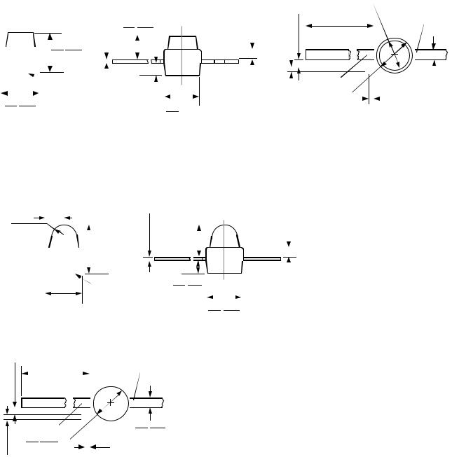
(C) Flat Top Detectors |
|
|
|
|
1.40 |
(0.055) |
|
|
|
|||||||||
|
|
|
0.50 (0.020) REF. |
(0.065) |
|
|
|
|||||||||||
|
|
|
|
|
|
|
|
|
|
|
|
|
1.65 |
|
|
|
||
|
|
|
|
|
|
|
|
|
1.14 |
(0.045) |
0.58 |
(0.023) |
|
|
|
CATHODE |
||
|
|
|
|
|
|
|
|
|
|
|
|
|
|
|
||||
|
|
|
|
|
|
|
|
|
0.43 |
(0.017) |
11.68 (0.460) |
|
|
|
|
|||
|
|
|
|
|
|
|
|
|
1.40 |
(0.055) |
|
|
|
|
||||
|
|
|
|
|
|
|
|
|
|
|
|
|
10.67 (0.420) |
|
|
|
|
|
|
|
|
|
|
|
|
|
|
|
|
|
|
|
|
|
|
||
|
|
|
|
|
1.91 |
(0.075) |
|
|
|
|
|
BOTH SIDES |
|
|
|
|||
|
|
|
|
|
2.41 |
(0.095) |
|
|
|
|
|
|
|
|
|
|
|
|
|
|
|
|
|
|
|
|
|
|
|
|
|
|
|
|
|
|
|
|
|
|
|
|
|
|
|
|
0.76 (0.030) MAX. |
|
ANODE |
|
|
|
0.46 |
(0.018) |
||
|
|
|
|
|
|
|
|
|
|
|
|
|
|
|
||||
|
|
|
|
|
|
|
|
|
|
|
|
|
|
|
||||
|
|
|
|
|
|
|
|
|
|
|
|
|
|
0.56 |
(0.022) |
|||
|
|
|
|
|
|
CATHODE |
|
|
|
|
|
|
|
|
||||
|
|
|
|
|
|
|
|
|
|
1.65 |
(0.065) |
|
|
|
|
|
||
|
|
|
|
|
|
STRIPE |
|
|
|
|
|
|
|
|
|
|||
|
|
|
|
|
|
|
|
|
|
1.91 |
(0.075) DIA. |
0.25 (0.010) MAX.* |
||||||
2.08 |
(0.082) |
|
NOTE 3 |
0.18 |
(0.007) |
|
|
|||||||||||
|
|
1.91 (0.075) |
|
|
|
|
NOTE 2 |
|
||||||||||
2.34 |
(0.092) |
|
|
|
0.23 |
(0.009) |
|
0.20 (0.008) MAX. |
|
|
|
|||||||
|
|
|
|
|
|
|
|
|
|
|
2.16 (0.085) |
|
|
|
|
|
|
|
(D) Dome Detectors
0.76 |
(0.030) |
|
|
|
|
|
|
0.18 |
(0.007) |
|
|
|
0.89 |
(0.035)R. |
|
|
|
|
|
|
|
||||
0.94 (0.037) |
0.23 |
(0.009) |
|
|
|
|||||||
|
|
|
|
|
|
|
||||||
|
|
|
|
1.24 (0.049) |
|
|
|
|
|
|||
|
|
|
|
|
|
|
|
|
2.03 (0.080) |
|
||
|
|
|
|
|
|
|
2.92 (0.115) |
|
1.78 (0.070) |
|
||
|
|
|
|
|
|
|
MAX. |
|
|
|
|
|
|
|
|
|
|
|
|
|
|
|
|
|
|
|
|
|
|
|
|
|
|
|
|
|
|
|
|
|
|
|
|
|
|
|
|
0.63 |
(0.025) |
||
|
|
|
|
|
|
|
|
|
||||
|
|
|
|
|
|
|
|
|
0.79 (0.031) |
(0.015) |
||
|
|
|
|
|
|
|
CATHODE |
|
0.38 |
|||
|
|
|
|
|
|
|
|
0.53 (0.021) |
|
|||
|
|
|
|
|
|
|
STRIPE |
|
|
|||
|
|
|
|
|
|
|
|
|
|
|
|
|
|
2.08 (0.082) |
NOTE 3 |
|
1.91 (0.075) |
|
|||||||
|
2.34 |
(0.092) |
|
|
|
|||||||
|
|
|
2.16 (0.085) |
|
||||||||
|
|
|
|
|
|
|
|
|
|
|||
0.50 (0.020) REF. |
|
|
|
|
|
|
||
|
|
|
|
|
|
CATHODE |
||
|
11.68 |
(0.460) |
|
|
|
|
||
|
10.67 |
(0.420) |
|
|
|
|
||
|
BOTH SIDES |
|
|
|
||||
|
ANODE |
|
|
|
0.46 |
(0.018) |
||
|
|
|
|
|||||
|
|
|
|
|||||
|
|
|
|
|||||
|
0.56 |
(0.022) |
||||||
1.65 |
(0.065) |
|||||||
DIA. |
|
|||||||
1.91 |
(0.075) |
|
||||||
|
|
|
|
|
0.25 (0.010) MAX.* |
|||
NOTE 2
0.20 (0.008) MAX.
NOTES:
1.ALL DIMENSIONS ARE IN MILLIMETERS (INCHES).
2.PROTRUDING SUPPORT TAB IS CONNECTED TO CATHODE LEAD.
3.CATHODE STRIPE MARKING IS SILVER.
4-71
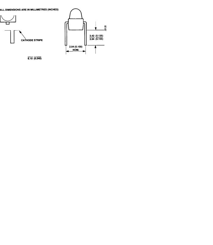
Package Dimensions
The following notes affect the package outline drawings E through I.
1.The pinout represents the HSDL-54XX IR detectors where the protruding support tab is closest to the anode lead. While the pinout is reversed for the HSDL-44XX
(E) Gull Wing Lead, Option 011
IR emitters where the protruding support tab is closest to the cathode lead.
2.The protruding support tab of the HSDL-54XX is connected to the cathode lead. While the protruding support tab of the HSDL-44XX is connected to the anode lead.
0.76 (0.030) MAX.
(F) “Yoke” Lead, Options 021
0.76 (0.030) MAX.
ALL DIMENSIONS ARE IN MILLIMETRES (INCHES)
4-72
(G) Z-Bend Lead, Options 031
0.76 (0.030) MAX.
(H) Thru Hole Lead Option 1L1
(I) Thru Hole Lead Option 1S1
4-73
Loading...