


8903B
Table of contents
 Loading...
Agilent Technologies. Inc
24001
E
Mission
Liberty
take, WA
99019
www
agilent
corn
..
,
.':tis:.
.
Ag
i
I
en
t
Technologies
:
.
:
.
Innovating
the
HP
Way
.**e..
June
8,2000
Dear Customer,
As
of
November
1,1999,
four of Hewlett-Packard's businesses, test and measurement,
semiconductor products, health care solutions, and chemical analysis became a new company,
Agilent Technologies. Now, many of your Hewlett-Packard products and services are in the care
of
Agilent Technologies.
At Agilent Technologies, we are working diligently to make this transition as smooth as possible for
you. However, as a result of this transition, the products and related documentation contained in this
shipment may be labeled with either the Hewlett-Packard name and logo, the Agilent Technologies
name and logo, or a combination
of
both. Information in this package may refer to Hewlett-Packard
(HP), but applies to your Agilent Technologies product. Hewlett-Packard and Agiient branded
products with the same model number are interchangeable.
Whatever logo you see, the information, products, and services come from the same reliable source.
If
you have questions about Agilent Technologies products and services, please visit our website at
http://www. anilent.com.
Sincerely,
Rebranding
Team
HP
8903B
AUDIO
ANALYZER
(Including Option
001)
Operation and Calibration Manual
Operation and Calibration Manual HP Part 08903-90079
Other Documents Available:
Service Manual (Volume
1,
2)
HP Part 08903-90062
Microfiche Operation and Service Manual HP Part 08903-90080
Printed in U.S.A.
:
November 1989
SERIAL
NUMBERS
This
manual applies directly to instruments with
serial numbers prefixed
2450A
to
2922A
and all
Mqior
changes that apply
to
your
instrument.
rev.ZOJUN91
For
additional important information about serial
numbers, refer
to
“INSTRUMENTS COVERED
BY
THIS
MANUAL’’
in Section
1.
Fourth Edition
This
material may be reproduced by
or
for the
US.
Government pursuant
to
the Copyright License
un-
der the clause at
DFARS
52.227-7013
(AF’R
1988).
Copyright
GHEWLETT-PACKARD COMPANY 1985
EAST 24001
MISSION
AVENUE, TAF C-34, SPOKANE, WASHINGTON, U.S.A. 99220
HEW
LETT@
PACKARD
1
Regulatory Information
(Updated
March
1999)
1
Regulatory
Information
(Updated
March
1999)
Safety Considerations
GENEFtAL
This product and related documentation must be reviewed for familiarization with safety
markings and instructions before operation.
This product has been designed and tested in accordance with
IEC
Publication
1010,
"Safety Requirements for Electronic Measuring Apparatus," and has been supplied in
a
safe condition. This instruction documentation contains information and warnings which
must be followed by the user
to
ensure safe operation and
to
maintain the product in a safe
condition.
SAFETY EARTH GROUND
A
uninterruptible safety earth ground must be provided from the main power source
to
the
product input wiring terminals, power cord,
or
supplied power cord set.
SAFETY
SYMBOLS
A
Indicates instrument damage can occur
if
indicated operating limits are exceeded.
A
Indicates hazardous voltages.
&
-
Indicates earth (ground) terminal
~~~~ ~
~ ~
WARNING
A
WARNING
note denotes a hazard. It calls attention to a procedure,
practice, or the like, which,
if
not correctly performed or adhered to,
could result in personal injury.
Do
not proceed beyond a
WARNING
sign until the indicated conditions are fully understood and met.
~
CAUTION
A
CAUTION note denotes a hazard. It calls attention
to
an operation
procedure, practice,
or
the like, which, if not correctly performed
or
adhered
to,
could result in damage
to
or
destruction
of
part
or
all of the product.
Do
not proceed beyond an CAUTION note until the indicated conditions are hlly
understood and met.
2
Chapter
1
Regulatory
Information
(Updated
March
1999)
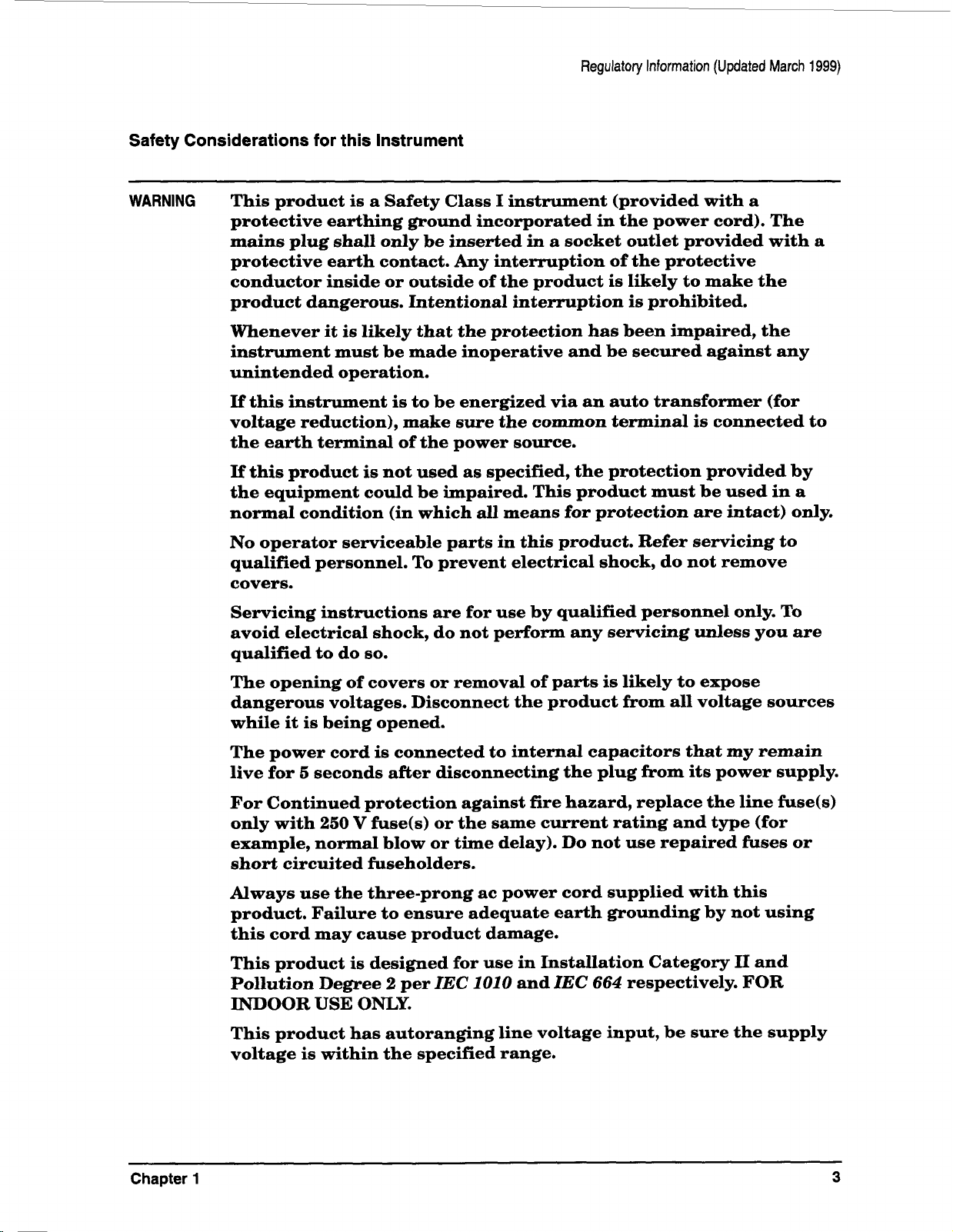
Safety Considerations for this Instrument
WARNING
This product is
a
Safety Class
I
instrument (provided with
a
protective earthing ground incorporated in the power cord). The
mains plug shall only be inserted in
a
socket outlet provided with a
protective earth contact. Any interruption of the protective
conductor inside or outside of the product is likely
to
make the
product dangerous. Intentional interruption
is
prohibited.
Whenever it
is
likely that the protection has been impaired, the
instrument must be made inoperative and be secured against any
unintended operation.
If
this instrument
is
to be energized
via
an auto transformer (for
voltage reduction), make sure the common terminal
is
connected
to
the earth terminal of the power source.
If
this product
is
not used as specified, the protection provided by
the equipment could be impaired. This product must be used in
a
normal condition (in which
all
means for protection are intact) only.
No
operator serviceable parts in this product. Refer servicing to
qualified personnel. To prevent electrical shock, do not remove
covers.
Servicing instructions are for use by qualified personnel only. To
avoid electrical
shock,
do not perform any servicing unless you are
qualified to do
so.
The opening
of
covers
or
removal of parts
is
likely to expose
dangerous voltages. Disconnect the product from
all
voltage sources
while it
is
being opened.
The power cord
is
connected to internal capacitors that
my
remain
live for
5
seconds after disconnecting the plug
from
its
power supply.
For Continued protection against fire hazard, replace the line fuse(s)
only with
250
V
fuse(s) or the same current rating and type (for
example, normal blow
or
time delay). Do not use repaired fuses or
short circuited fuseholders.
Always use the three-prong ac power cord supplied with this
product. Failure
to
ensure adequate earth grounding by not using
this cord may cause product damage.
This product
is
designed for use in Installation Category
I1
and
Pollution Degree
2
per
IEC
1010
and
IEC
664
respectively. FOR
INDOOR
USE
ONLY.
This product has autoranging line voltage input, be sure the supply
voltage is within the specified range.
~~~~
Chapter
1
3

Regulatory Information (Updated
March
1999)
To
prevent electrical shock, disconnect instrument from mains (line)
before cleaning. Use a dry cloth or one slightly dampened with water
to clean the external case parts.
Do
not attempt to clean internally.
Ventilation Requirements: When installing the product in a cabinet,
the convection into and out of the product must not be restricted.
The ambient temperature (outside the cabinet) must be less than the
maximum operating temperature of the product by
4"
C
for every
100
watts dissipated in the cabinet.
If
the total power dissipated in the
cabinet
is
greater than
800
watts, then forced convection must be
used.
Product
Markings
CE
-
the CE mark
is
a registered trademark
of
the European Community.
A
CE mark
accompanied by
a
year indicated the year the design was proven.
CSA
-
the
CSA
mark
is
a registered trademark
of
the Canadian Standards Association.
4
Chapter
1
CERTIFICATION
Hewlett-Packard Company certifies
that
this
product met
its
published specifications at
the
time of shipment
from
the factom. Hewlett-Packard further certifies that its calibration measurements are traceable to the
United States National Bureau of Standards, to the extent allowed
by
the
Bureau's calibration facility, and
to the calibration facilities of other International Standards Organization members.
WARRANTY
This Hewlett-Packard instrument product is warranted against defects
in
material and workmanship for a
period of one year from
date
of shipment. During the warranty period, Hewlett-Packard Company will at
its
option, either repair
or
replace products which prove
to
be defective.
For
warranty senrice
or
repair, this product must be returned
to
a service facility designated by HP. Buyer
shall prepay shipping charges to
HP
and HP shall pay shipping charges to return the product
to
the Buyer.
However, Buyer shall pay all shipping charges, duties, and taxes for products returned
to
HP from another
country.
HP warrants that its software and firmware designated by HP for use with an instrument will execute
its programming instructions when properly installed on that instrument. HP does not warrant that the
operation of the instrument,
or
sohare,
or
firmware will be uninterrupted
or
error free.
LIMITATION
OF
WARRANTY
The foregoing warranty shall not apply to defects resulting from improper
or
inadequate maintenance by
Buyer, Buyer-supplied software
or
interfacing, unauthorized modification
or
misuse, operation outside of the
environmental specifications
for
the product,
or
improper site preparation
or
maintenance.
NO OTHER WARRANTY
IS
EXPRESSED OR IMPLIED. HP SPECIFICALLY DISCLAIMS THE
IMPLIED WARRANTIES
OF
MERCHANTABILITY AND FITNESS FOR
A
PAWICULAR PURPOSE.
EXCLUSIVE REMEDIES
THE REMEDIES PROVIDED HEREIN ARE BUYERS SOLE AND EXCLUSIVE REMEDIES.
HP
SHALL NOT BE LIABLE FOR
ANY
DIRECT, INDIRECT, SPECIAL, INCIDENTAL, OR
CONSEQUENTIAL DAMAGES, WHETHER BASED ON CONTRACT, TOFU', OR
ANY
OTHER
LEGAL THEORY.
ASSISTANCE
Product maintenance agreements and other customer assistance agreements are available for Hewlett-
Packard products.
For
any assistance, contact your nearest Hewlett-Packard Sales and Service Office. Addresses are provided
at the back
of
this manual.
Model
8903B
Safety Considerations
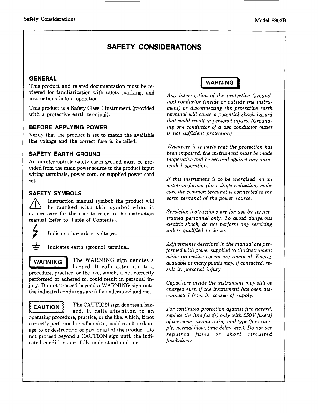
SAFETY
CONSIDERATIONS
GENERAL
This product and related documentation must be re-
viewed for familiarization with safety markings and
instructions before operation.
This product
is
a Safety Class
I
instrument (provided
with a protective earth terminal).
BEFORE
APPLYING
POWER
Verify that the product is set to match the available
line voltage and the correct fuse
is
installed.
SAFETY EARTH GROUND
An uninterruptible safety earth ground must be pro-
vided from the main power source to the product input
wiring terminals, power cord,
or
supplied power cord
set.
SAFETY SYMBOLS
Instruction manual symbol: the product will
/I\
be marked with this symbol when
it
is
necessary for the user to refer to the instruction
manual (refer to Table of Contents).
Indicates hazardous voltages.
Indicates earth (ground) terminal.
The WARNING sign denotes a
hazard. It calls attention to a
procedure, practice,
or
the like, which,
if
not correctly
performed
or
adhered to, could result in personal in-
jury.
Do
not proceed beyond a WARNING sign until
the indicated conditions are fully understood and met.
The
CAUTION
sign denotes a haz-
ard. It calls attention to an
operating procedure, practice,
or
the like, which, if not
correctly performed
or
adhered to, could result in dam-
age to
or
destruction of part
or
all of the product.
Do
not proceed beyond a CAUTION sign until the indi-
cated conditions are fully understood and met.
(WARNING
I
Any interruption of the protective (ground-
ing) conductor (inside
or
outside
the
instru-
ment)
or
disconnecting the protective earth
terminal will cause a potential shock hazard
that could result
in
personal injury. (Ground-
ing one conductor of a two conductor outlet
is not sufficient protection).
Whenever it
is
likely that the protection has
been impaired, the instrument
must
be made
inoperative and be secured against any unin-
tended operation.
If this instrument is to be energized via an
autotransformer (for voltage reduction) make
sure the common terminal
is
connected to the
earth terminal
of
the power source.
Servicing instructions are
for
use by service-
trained personnel only.
To
avoid dangerous
electric shock, do not perform any servicing
unless qualified to do
so.
Adjustments described
in
the manual are per-
formed with power supplied to the instrument
while protective covers are removed. Energy
available at manypoints may,
if
contacted, re-
sult in personal injury.
Capacitors inside the instrument may still be
charged even
if
the instrument
has
been dis-
connected from its source of supply.
For
continued protection against fire hazard,
replace the line fuse(s) only with
250V
fuse(s)
of the same current rating and type (for exam-
ple, normal blow, time delay, etc.).
Do
not use
rep a ired fuses
o
r
s
ho
r
t
c irc
u
i
t ed
fuseholders.
Model
8903B
Safety Considerations
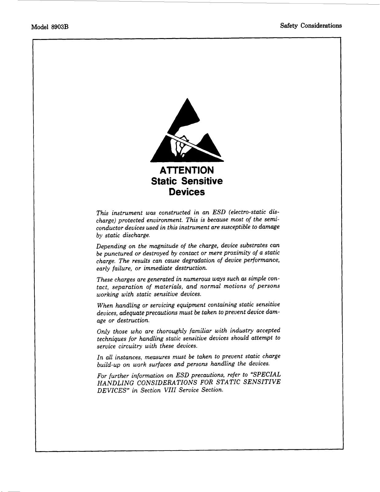
ATTENTION
Static Sensitive
Devices
This instrument was constructed in an ESD (electro-static dis-
charge) protected environment. This is because most of the semi-
conductor devices used
in
this
instrument are susceptible to damage
by static discharge.
Depending on the magnitude of the charge, device substrates can
be punctured
or
destroyed by contact
or
mere proximity of a static
charge. The results can cause degradation of device performance,
early failure,
or
immediate destruction.
These charges are generated
in
numerous ways such
as
simple con-
tact, separation of materials, and normal motions of persons
working with static sensitive devices.
When handling
or
servicing equipment containing static sensitive
devices, adequate precautions must be taken to prevent device dam-
age
or
destruction.
Only those who are thoroughly familiar with industry accepted
techniques for handling static sensitive devices should attempt to
service circuitry with these devices.
In all instances, measures must be taken to prevent static charge
build-up on work surfaces and persons handling the devices.
For
further information on ESD precautions, refer to “SPECIAL
HANDLING CONSIDERATIONS
FOR
STATIC SENSITIVE
DEVICES,’
in
Section VIII Service Section.
HP 8903B
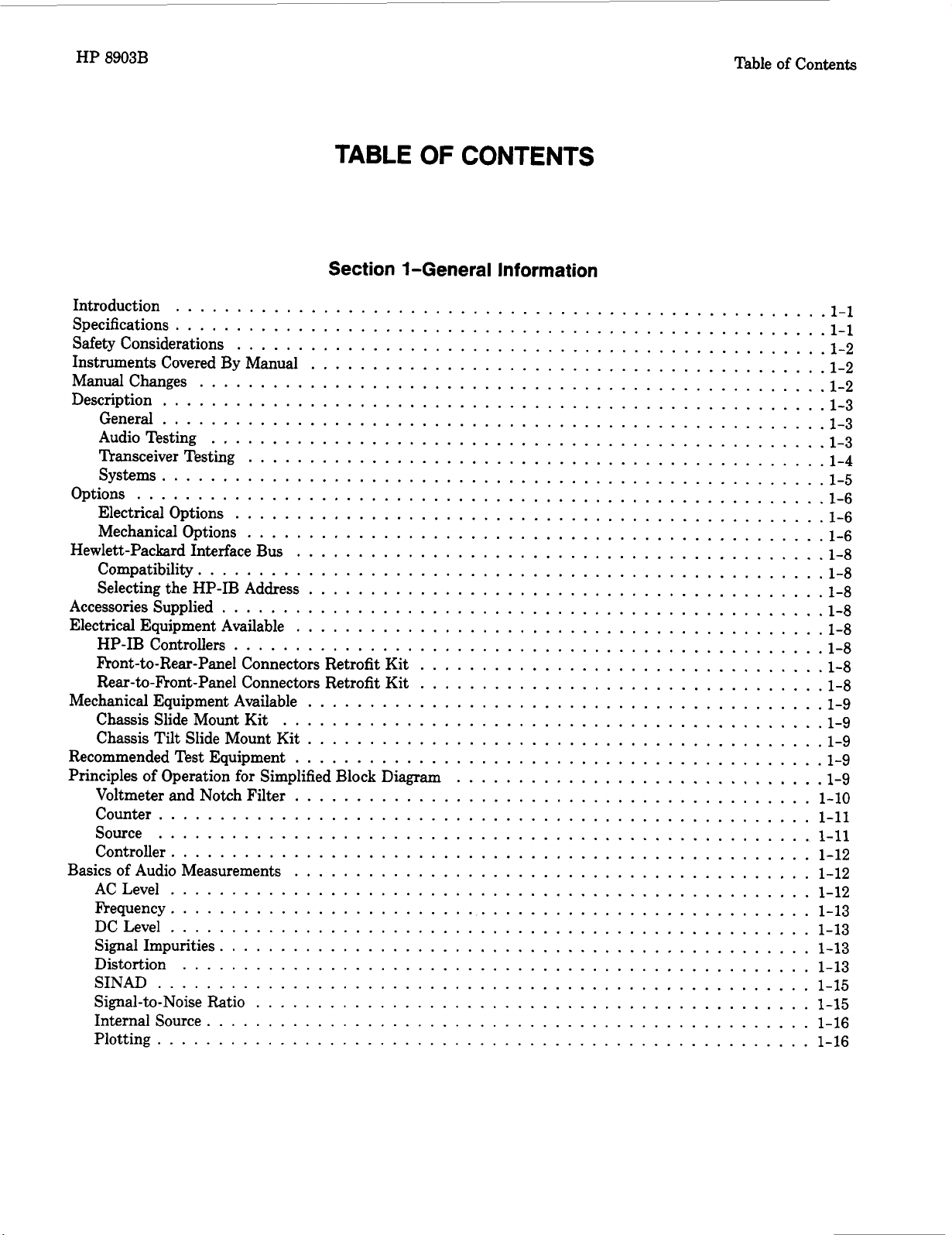
TABLE
OF
CONTENTS
Section +General Information
Table
of
Contents
Introduction
1.1
Specifications
.....................................................
1-1
Safety Considerations
................................................
1.2
Instruments Covered By Manual
..........................................
1.2
Manualchanges
...................................................
1-2
Description
......................................................
1-3
General
......................................................
1-3
Audio Testing
..................................................
1-3
Transceiver Testing
...............................................
1-4
Systems
......................................................
1-5
Options
........................................................
1-6
Electrical Options
................................................
1-6
Mechanical Options
...............................................
1-6
Hewlett-Packard Interface Bus
...........................................
1-8
Compatibility
...................................................
1-8
Selecting the HP-IB Address
..........................................
1-8
Accessories Supplied
.................................................
1-8
Electrical Equipment Available
...........................................
1-8
HP-IB Controllers
................................................
1-8
Front-to-Rear-Panel Connectors Retrofit Kit
.................................
1-8
Rear-to-Front-Panel Connectors Retrofit Kit
.................................
1-8
Mechanical Equipment Available
..........................................
1-9
Chassis Slide Mount Kit
............................................
1-9
Chassis Tilt Slide Mount Kit
..........................................
1-9
Recommended Test Equipment
...........................................
1-9
Principles
of
Operation
for
Simplified Block Diagram
..............................
1-9
Voltmeter and Notch Filter
..........................................
1-10
Counter
.....................................................
1-11
Source
.....................................................
1-11
Controller
....................................................
1-12
Basics
of
Audio Measurements
..........................................
1-12
ACLevel
....................................................
1-12
Frequency
....................................................
1-13
DCLevel
....................................................
1-13
Signal Impurities
................................................
1-13
Distortion
...................................................
1-13
Signal-to-Noise Ratio
.............................................
1-15
Internal Source
.................................................
1-16
Plotting
.....................................................
1-16
.....................................................
SINAD
.....................................................
1-15
HP
8903B
Table
of
Contents
Section 2-Installation
Introduction
.....................................................
2.1
Initial Inspection
...................................................
2.1
Preparation
for
Use
.................................................
2.1
Power Requirements
...............................................
2.1
Line Voltage and Fuse Selection
........................................
2-2
Power Cables
...................................................
2.2
HP-IB Address Selection
............................................
2.3
Interconnections
.................................................
2.5
Mating Connectors
...............................................
2.5
Operating Environment
...............................................
2.6
Bench Operation
.................................................
2.6
Rack Mounting
..................................................
2.6
Storage and Shipment
................................................
2.8
Packaging
.....................................................
2.8
Environment
...................................................
2.8
Section %Operation
....................................................
Introduction
-3-1
General
......................................................
3-1
"urn-On Procedure
3-1
Local Operation
3-2
Remote Operation
3-3
Operating Characteristics
............................................
3-1
...............................................
..................................................
................................................
Operator's Checks
..................................................
3-3
Operator's Maintenance
.............................................
3-4
Front-Panel Features
.................................................
3-6
Basic Functional Checks
3-12
Simplified Operation
.................................................
3-8
Rear-Panel Features
3-11
Description
3-12
Equipment
3-12
Procedure
3-12
Preliminary Check
3-12
Filter Check
3-13
Distortion Check
3-15
SINAD Check
3-15
..............................................
................................................
...................................................
...................................................
....................................................
...............................................
AC Level and Output Level Check
......................................
3-12
..................................................
................................................
.................................................
Signal-to-Noise Ratio Check
.........................................
3-15
Sweep,
X
Axis,
Y
Axis, Pen Lift, and DC Level Check
...........................
3-15
.............................................
...................................................
..................................................
...................................................
HP-IB Functional Checks
3-16
Description
3-16
Initial Setup
3-16
Equipment
3-16
Address Recognition
..............................................
3-16
Remote and Local Messages and the LCL Key
...............................
3-17
Receiving the Data Message
.........................................
3-18
Local Lockout and Clear Lockout/Set Local Messages
...........................
3-18
..........................................
Sending the Data Message
3-17
HP 8903B
Table
of
Contents
ClearMessage
.................................................
3-18
AbortMessage
.................................................
3-19
Status Byte Message
..............................................
3-20
Require Service Message
...........................................
3-21
Trigger Message and Clear Key Triggering
..................................
3-22
Remote Operation. Hewlett-Packard Interface Bus
...............................
3-22
HP-IB Compatibility
.............................................
3-23
Remote Mode
.................................................
3-23
LocalMode
...................................................
3-23
Addressing
...................................................
3-23
Data Messages
.................................................
3-26
Receiving the Data Message
.........................................
3-26
Sending the Data Message
..........................................
3-30
Receiving the Clear Message
.........................................
3-31
Receiving the Trigger Message
........................................
3-32
Receiving the
Remote
Message
........................................
3-32
Receiving the Local Message
.........................................
3-33
Receiving the Local Lockout Message
....................................
3-33
Receiving the Clear Lockout/Set Local Message
..............................
3-33
Receiving the Pass Control Message
.....................................
3-33
Sending the Require Service Message
....................................
3-33
Selecting the Service Request Condition
...................................
3-34
Sending the Status Byte Message
......................................
3-34
Sending the Status Bit Message
.......................................
3-35
Receiving the Abort Message
.........................................
3-35
HP-IB
Syntax
and Characteristics Summary
..................................
3-35
Amplitude
.......................................................
3-44
Automatic Operation
................................................
3-46
ACLevel
......................................................
3-42
CommonMode
...................................................
3-47
DCLevel
......................................................
3-50
Default Conditions and Power-up Sequence
...................................
3-52
Detector Selection
.................................................
3-53
Display Level in Watts
...............................................
3-55
Display Source Settings
..............................................
3-57
Distortion
......................................................
3-58
Distortion Level
..................................................
3-60
Error Disable
....................................................
3-62
Error Message Summary
..............................................
3-64
Filters
........................................................
3-68
Float
.........................................................
3-72
Frequency
......................................................
3-74
Hold Decimal Point
................................................
3-76
Hold Settings
....................................................
3-78
HP-IB Address 3-79
Increment
......................................................
3-82
Input Level Range (DC Level)
..........................................
3-84
Input Level Range (Except DC Level)
......................................
3-86
Monitor
.......................................................
3-88
Notch~ne
.....................................................
3-91
Output Impedance
.................................................
3-93
Plot Limit 3-96
Post-Notch Detector Filtering (Except SINAD)
.................................
3-98
...................................................
......................................................

Table of Contents HP 8903B
Post-Notch Gain
.................................................
Rapid Frequency Count
.............................................
Rapidsource
...................................................
RATIO and LOG/LIN
..............................................
Read Display
to
HP-IB
.............................................
Service Request Condition
............................................
Signal-to-Noise
..................................................
Special Functions
.................................................
Sweep
.......................................................
Sweep Resolution
.................................................
Time Between Measurements
..........................................
X-YRecording
..................................................
3-100
3-102
3-105
3-109
3-112
3-114
3-116
3-121
3-128
3-131
3-134
3-135
Section 4-Performance
Introduction
.....................................................
4.1
Equipment Required
.................................................
4.1
TestRecord
......................................................
4-1
Calibration Cycle
...................................................
4.1
Abbreviated Performance Testing
..........................................
4.1
Performance Test
1
AC
Level Accuracy and Output Level Accuracy and Flatness
...............
4-2
Performance Test
2
DC Level Accuracy
.....................................
4-12
Performance Test 3 Distortion and Noise
....................................
4-14
Performance Test 4 Distortion, SINAD, and Signal-to-Noise Accuracy
....................
4-16
Performance Test 5 Frequency Accuracy and Sensitivity
............................
4-19
Performance Test 6 Audio Filters
.........................................
4-21
Performance Test
7
Input and Output Impedance
................................
4-28
Performance Test
8
Common-Mode Rejection Ratio
..............................
4-29
Section 5-Adjustments
Introduction
.....................................................
5.1
Safety Considerations
................................................
5.1
Equipment Required
.................................................
5.1
Factory-Selected Components
............................................
5.1
Post-Repair Tests, Adjustments, and Checks
....................................
5.2
Related Adjustments
.................................................
5.2
Adjustment
1
Internal Reference Frequency
....................................
5.4
Adjustment
2
Input Flatness
............................................
5.5
Adjustment 3 Common Mode Rejection
......................................
5.8
Adjustment 4 Input DC
Offset
...........................................
5.9
Adjustment 5 400 Hz High-Pass and Weighting Bandpass Filters
.......................
5-10
Adjustment 6 Notch Filter Tune and Balance
..................................
5-12
Adjustment
7
Voltmeter
..............................................
5-13
Adjustment
8
SINAD Meter
............................................
5-15
Adjustment 9 Oscillator and Output Attenuator
.................................
5-16
Model
8903B
General Information
Section
1
GENERAL INFORMATION
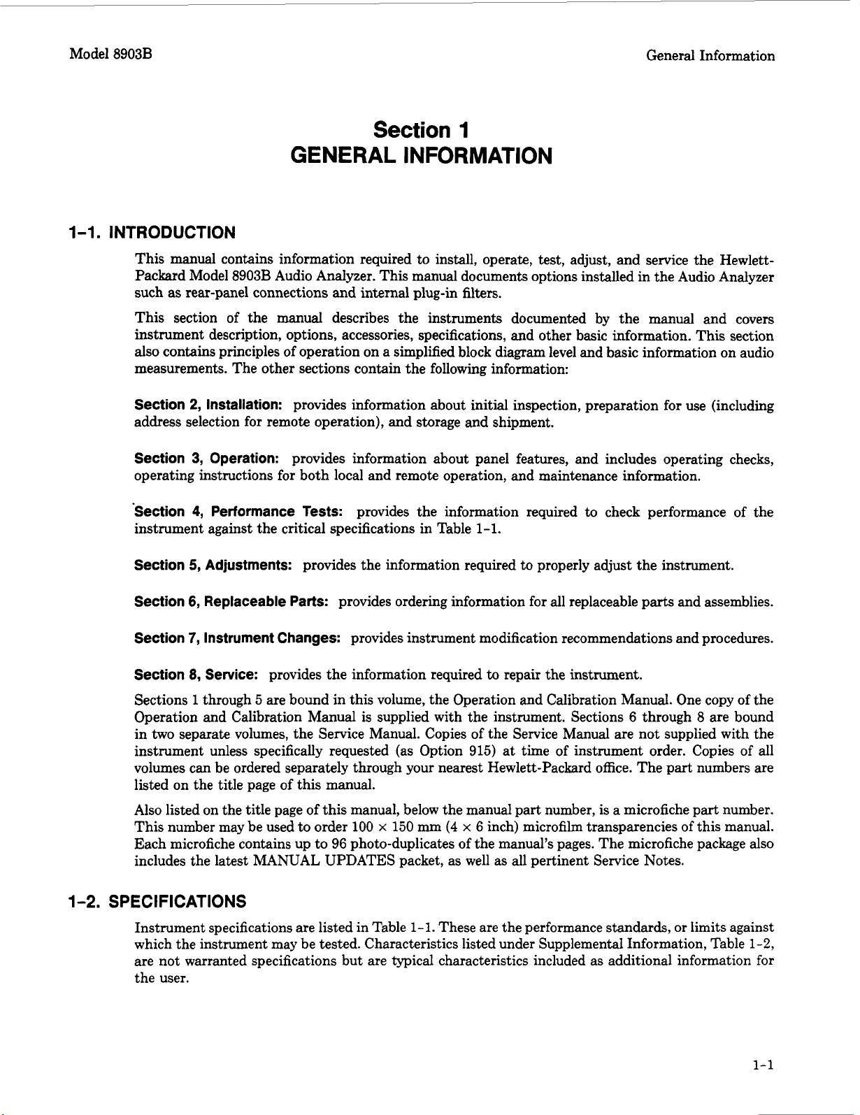
1-1.
INTRODUCTION
This manual contains information required to install, operate, test, adjust, and service the Hewlett-
Packard Model 8903B Audio Analyzer. This manual documents options installed in the Audio Analyzer
such
as
rear-panel connections and internal plug-in filters.
This section of the manual describes the instruments documented by the manual and covers
instrument description, options, accessories, specifications, and other basic information. This section
also contains principles of operation on a simplified block diagram level and basic information on audio
measurements. The other sections contain the following information:
Section
2,
Installation:
provides information about initial inspection, preparation for use (including
address selection for remote operation), and storage and shipment.
Section
3,
Operation:
provides information about panel features, and includes operating checks,
operating instructions for both local and remote operation, and maintenance information.
Section
4,
Performance Tests:
provides the information required
to
check performance of the
instrument against the critical specifications in Table
1-1.
Section
5,
Adjustments:
provides the information required to properly adjust the instrument.
Section
6,
Replaceable Parts:
provides ordering information for all replaceable parts and assemblies.
Section
7,
Instrument Changes:
provides instrument modification recommendations and procedures.
Section
8,
Service:
provides the information required
to
repair the instrument.
Sections
1
through
5
are bound in this volume, the Operation and Calibration Manual. One copy of the
Operation and Calibration Manual is supplied with the instrument. Sections 6 through
8
are bound
in
two
separate volumes, the Service Manual. Copies of the Service Manual are not supplied with the
instrument unless specifically requested (as Option 915) at time of instrument order. Copies of all
volumes can be ordered separately through your nearest Hewlett-Packard office. The part numbers are
listed on the title page of this manual.
Also listed on the title page of this manual, below the manual part number, is
a
microfiche part number.
This number may be used to order 100
x
150
mm
(4
x
6 inch) microfilm transparencies of this manual.
Each microfiche contains up to 96 photo-duplicates of the manual’s pages. The microfiche package also
includes the latest MANUAL UPDATES packet, as well as all pertinent Service Notes.
1-2.
SPECIFICATIONS
Instrument specifications are listed in Table
1-1.
These are the performance standards, or limits against
which the instrument may be tested. Characteristics listed under Supplemental Information, Table
1-2,
are not warranted specifications but are typical characteristics included as additional information for
the user.
1-1
General Information Model
8903B
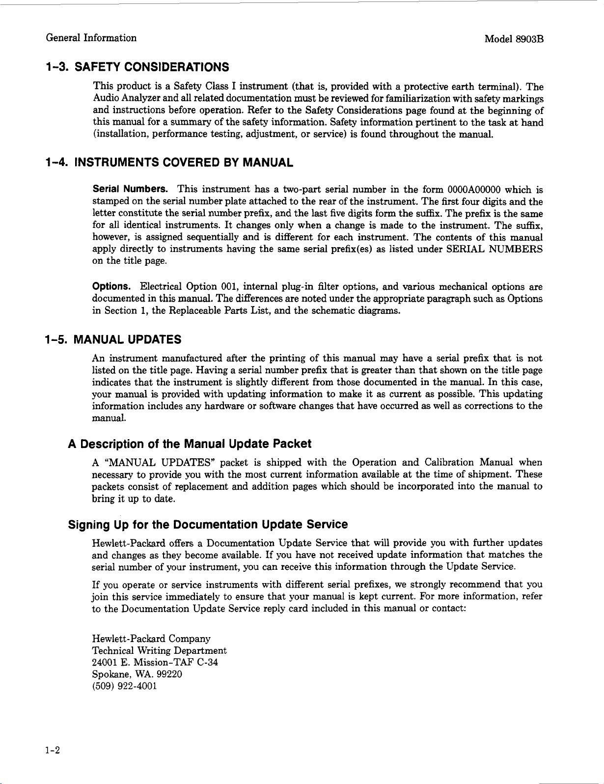
1-3.
SAFETY CONSIDERATIONS
This product is a Safety
Class
I instrument (that is, provided with a protective earth terminal). The
Audio Analyzer and all related documentation must be reviewed for familiarization with safety markings
and instructions before operation. Refer to the Safety Considerations page found at the beginning of
this manual
for
a summary of the safety information. Safety information pertinent to the task at hand
(installation, performance testing, adjustment,
or
service) is found throughout the manual.
1-4.
INSTRUMENTS COVERED
BY
MANUAL
Serial
Numbers.
This instrument has a two-part serial number in the form
OOOOAOOOOO
which is
stamped on the serial number plate attached to the rear
of
the instrument. The first four digits and the
letter constitute the serial number prefix, and the last five digits form the suffix. The prefix is the same
for all identical instruments.
It
changes only when a change
is
made to the instrument. The suffix,
however,
is
assigned sequentially and is different for each instrument. The contents of this manual
apply directly to instruments having the same serial prefix(es) as listed under SERIAL NUMBERS
on the title page.
Options.
Electrical Option
001,
internal plug-in filter options, and various mechanical options are
documented in this manual. The differences are noted under the appropriate paragraph such
as
Options
in Section
1,
the Replaceable Parts List, and the schematic diagrams.
1-5.
MANUAL UPDATES
An instrument manufactured after the printing of this manual
may
have
a
serial prefix that
is
not
listed on the title page. Having a serial number prefix that
is
greater than that shown on the title page
indicates that the instrument is slightly different from those documented in the manual. In this case,
your manual
is
provided with updating information to make it as current
as
possible. This updating
information includes any hardware
or
software changes that have occurred as well as corrections to the
manual.
A Description
of
the Manual Update Packet
A
“MANUAL UPDATES” packet is shipped with the Operation and Calibration Manual when
necessary to provide you with the most current information available at the time
of
shipment. These
packets consist of replacement and addition pages which should be incorporated into the manual to
bring it up to date.
Signing Up
for
the Documentation Update Service
Hewlett-Packard offers a Documentation Update Service that will provide you with further updates
and changes as they become available. If you have not received update information that matches the
serial number of your instrument, you can receive this information through the Update Service.
If
you
operate
or
service instruments with different serial prefixes, we strongly recommend that you
join this service immediately to ensure that your manual is kept current. For more information, refer
to the Documentation Update Service reply card included in this manual
or
contact:
Hewlett-Packard Company
Technical Writing Department
24001
E.
Mission-TAF C-34
Spokane, WA. 99220
(509) 922-4001
1-2
Model 8903B
General Information
1-6.
DESCRIPTION
General
The HP Model 8903B Audio Analyzer is a complete audio measurement system covering the frequency
range of
20
Hz
to
100 kHz.
It
combines a low-distortion signal source with a signal analyzer. The
source has a maximum open-circuit output of 6 Vrms and a selectable output impedance of either
50
or
6000. The analyzer can perform distortion analysis, frequency count, and ac level, dc level, SINAD, and
signal-to-noise ratio measurements. The Audio Analyzer reduces the number of instruments required
in many applications involving audio signal characterization.
The Audio Analyzer is easy
to
use. All measurements are selected by one
or
two keystrokes. For
distortion measurements, the Audio Analyzer automatically tunes to and levels the input signal.
Measurement and output ranges are automatically selected for maximum resolution and accuracy.
firthermore, tuning is independent of the source. Thus, the source can be set to one frequency while
the analyzer
is
measuring the distortion on a signal
at
another frequency (that is, there
is
no need to
tune the analyzer
to
the source).
The combined capabilities of the instrument are enhanced by microprocessor control, resulting
in
more
capability than would be available from separate instruments. For example, when making signal-to-noise
ratio measurements, the Audio Analyzer monitors the ac level while turning the source on and
off.
The
microprocessor then computes and displays the ratio of the on and
off
levels. The ratio can be displayed
in either
5%
or
dB.
In addition, the source can be swept. This makes measurements such as frequency response
or
complete
distortion characterization simple
to
perform. Microprocessor control allows flexible entry of source
parameters and versatile display formats. For example, ac level can be displayed in V, mV, dBm into
6000, watts,
or
as a ratio (in
%
or
dB)
referenced to an entered
or
measured value.
Virtually all functions are remotely programmable through the Hewlett-Packard Interface Bus
(HP-IB'). Programming is easy
and
straightforward; all measurements are made through a single
input. This eliminates the need to switch between multiple inputs under remote control and reduces
software development time and hardware costs. The Audio Analyzer measures the true rms level
on all ac measurements. True rms measurements assure greater accuracy when measuring complex
waveforms and noise. For those applications where average detection
is
required, the analyzer can
be switched to average-responding
(rms
calibrated) detection through special functions. Accurate
distortion measurements typically can be made to less than
0.003%
(-90
dB)
between
20
Hz and
20
kHz
at
a 1.5V level. For those applications where quasi-peak detection
is
required, the analyzer
(Serial Prefix 2730A and above) can be switched
to
this type of detection through special functions.
This detector is designed
to
meet the requirements specified by CCIR 468-3.
Audio Testing
The Audio Analyzer has numerous features which make audio testing simple and convenient.
These features include flexible data entry and display formats, convenient source control, and swept
measurements capability.
For
example, distortion results can be displayed in
%
or
dB.
AC level
measurements can be displayed in volts, dBm into 600R,
or
watts. Measurement results can be displayed
in
%
or
dB
relative to a measured
or
entered value. Finding the
3
dB
points of filters and amplifiers
is simplified by using the source frequency increment and decrement keys together with the relative
display feature.
A
major contribution of the Audio Analyzer is its ability to make swept measurements.
When sweeping, the Audio Analyzer tuning steps
its
source frequency in logarithmic increments. With
an x-y recorder, hard copy measurement results can be obtained. X-axis scaling
is
determined by the
entered start and stop frequencies. Y-axis scaling
is
determined by the measurement units selected and
the plot limits entered through the keyboard. Any valid display units (except mV) are allowed when
plotting. To change the scaling from frequency response to swept distortion plots, simply key in new
HP-IB: Not just IEEE-488, but the hardware, documentation and support that delivers the shortest path to a
measurement system.
1-3
General Information Model
8903B
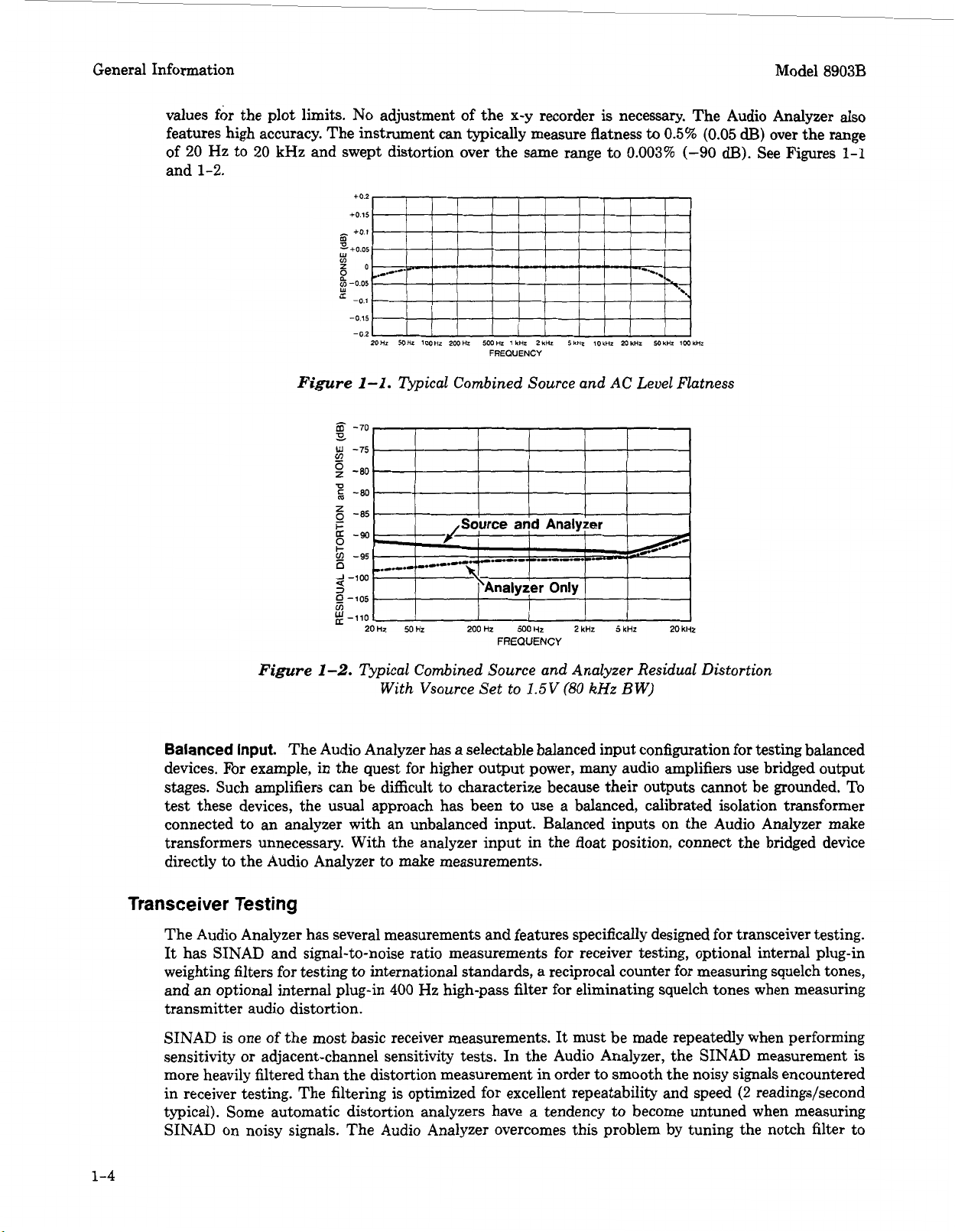
values for the plot limits.
No
adjustment of the x-y recorder
is
necessary. The Audio Analyzer also
features high accuracy. The instrument can typically measure flatness
to
0.5%
(0.05
dE3)
over the range
of
20
Hz to
20
kHz and swept distortion over the same range to
0.003%
(-90
dB).
See Figures
1-1
and
1-2.
+0.2,
I,,
I1
Figure
1-1.
npical Combined Source and
AC
Level Flatness
-70
9
w
-75
v,
g
-80
p
-80
'?o
-85
'0
-
I-
!
9
-95
D
3
0
-105
v)
-110
2
-100
20Hz
5OHz
2OOHz
500Hz
PkHr
5kHz
20kHz
FREQUENCY
Figure
1-2.
Typical Combined Source and Analyzer Residual Distortion
With Vsource Set to 1.5V
(80
kHz
BW)
Balanced
Input.
The Audio Analyzer has
a
selectable balanced input configuration for testing balanced
devices. For example, in the quest for higher output power, many audio amplifiers use bridged output
stages. Such amplifiers can be difficult to characterize because their outputs cannot be grounded. To
test these devices, the usual approach has been
to
use a balanced, calibrated isolation transformer
connected to an analyzer with an unbalanced input. Balanced inputs on the Audio Analyzer make
transformers unnecessary. With the analyzer input in the float position, connect the bridged device
directly to the Audio Analyzer to make measurements.
Transceiver Testing
The Audio Analyzer has several measurements and features specifically designed for transceiver testing.
It
has SINAD and signal-to-noise ratio measurements for receiver testing, optional internal plug-in
weighting filters for testing to international standards, a reciprocal counter for measuring squelch tones,
and an optional internal plug-in
400
Hz high-pass
filter
for eliminating squelch tones when measuring
transmitter audio distortion.
SINAD is one
of
the most basic receiver measurements. It must be made repeatedly when performing
sensitivity
or
adjacent-channel sensitivity tests. In the Audio Analyzer, the SIN AD measurement is
more heavily filtered than the distortion measurement in order to smooth the noisy signals encountered
in receiver testing. The filtering is optimized for excellent repeatability and speed
(2
readings/second
typical). Some automatic distortion analyzers have
a
tendency to become untuned when measuring
SINAD on noisy signals. The Audio Analyzer overcomes this problem by tuning the notch filter to
1-4
Model
8903B
General Information
the source frequency when measuring SINAD. SINAD measurement results are indicated both by the
digital display and a front-panel analog meter. The meter is specifically marked for
EIA
and CEPT
sensitivity and selectivity. For SINAD ratios less than
25
dB,
the digital display
is
automatically
rounded to the nearest
0.5
dB
to reduce digit flicker.
Signal-to-noise ratio measurements are also filtered for improved repeatability and speed
(1
read-
ing/second typical), and automatic display rounding
is
provided. For accurate noise measurements, the
Audio Analyzer uses true
rms
detection for both SINAD and signal-to-noise measurements. Most older
instruments employ average detection which reads low for noise. The discrepancy can be
1.5
dB
or
greater and varies with the ratio being measured. For correlating results with past test data, the Audio
Analyzer’s detector can be switched via special functions
to
an average responding configuration.
For those applications where quasi-peak detection is required, the analyzer (Serial Prefix
2730A
and
above) can be switched
to
this type of detection through special functions. This detector is designed
to
meet the requirements specified by CCIR
468-3.
For transceivers, the Audio Analyzer has an optional, internal plug-in seven-pole 400 Hz high-pass filter
for rejecting squelch tones. Rejection of squelch tones up to
250
Hz
is
greater than
40
dB.
Therefore,
audio distortion measurements
to
1%
residual distortion can be made without disabling the transmitter
squelch tones.
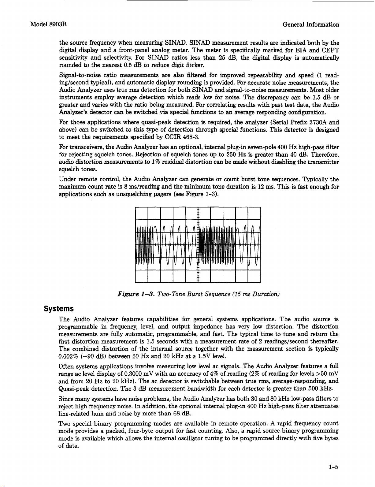
Under remote control, the Audio Analyzer can generate
or
count burst tone sequences. Typically the
maximum count rate
is
8
ms/reading and the minimum tone duration
is
12
ms. This
is
fast
enough for
applications such as unsquelching pagers (see Figure
1-3).
Figure
1-3.
Two-Tone
Burst
Sequence
(15
ms
Duration)
Systems
The Audio Analyzer features capabilities for general systems applications. The audio source
is
programmable in frequency, level, and output impedance has very low distortion. The distortion
measurements are fully automatic, programmable, and
fast.
The typical time
to
tune and return the
first distortion measurement
is
1.5
seconds with a measurement rate of
2
readings/second thereafter.
The combined distortion of the internal source together with the measurement section is typically
0.003%
(-90
dB)
between
20
Hz
and
20
kHz at a
1.5V
level.
Often systems applications involve measuring low level ac signals. The Audio Analyzer features a full
range ac level display of
0.3000
mV with an accuracy of
4%
of reading
(2%
of reading for levels
>50
mV
and from
20
Hz
to
20
kHz). The ac detector is switchable between true rms, average-responding, and
Quasi-peak detection. The
3
dB
measurement bandwidth for each detector is greater than
500
kHz.
Since many systems have noise problems, the Audio Analyzer has both
30
and
80
kHz low-pass filters
to
reject high frequency noise. In addition, the optional internal plug-in
400
Hz
high-pass filter attenuates
line-related hum and noise by more than
68
dB.
Two special binary programming modes are available in remote operation.
A
rapid frequency count
mode provides a packed, four-byte output for fast counting. Also, a rapid source binary programming
mode
is
available which allows the internal oscillator tuning to be programmed directly with five bytes
of data.
1-5
Model 8903B
General Information
1-7.
OPTIONS
Electrical Options
Electrical Option
001.
This option provides rear-panel (instead of front-panel) connections for both
the INPUT and OUTPUT HIGH and LOW BNC connectors.
Internal Plug-in Filter Options.
The Audio Analyzer has
two
plug-in filter positions; each position
can be loaded with any one of six optional filters. Each filter is referenced to its corresponding filter
position by one
of
two
option numbers. For example, the 400 Hz high-pass filter option can be ordered
as Option 010 which corresponds to the left-most filter position,
or
as
Option
050
which corresponds
to the right-most filter position. These optional plug-in filters can be configured in any combination
desired.
(If
there is no filter ordered for a position, a jumper
is
loaded and a label marked
“No
Filter”
is placed above the filter key on the front panel.) The following list includes the name and option
numbers for each available filter.
0
400 Hz High-Pass Filter (Option 010,050)
0
CCITT Weighting Filter (Option 011, 051)
0
CCIR Weighting Filter (Option 012, 052)
0
C-MESSAGE Weighting Filter (Option 013, 053)
0
CCIR/ARM Weighting Filter (Option 014,
054)
0
“A”
Weighting Filter (Option 015,
055)
Specific information on each plug-in filter option can be found in the Detailed Operating Instructions
in Section 3 under “Filters”.
Mechanical Options
The following options may have been ordered and received with the Audio Analyzer.
If
they were not
ordered with the original shipment and are now desired, they can be ordered from the nearest Hewlett-
Packard office using the part number included in each of the following paragraphs. The mechanical
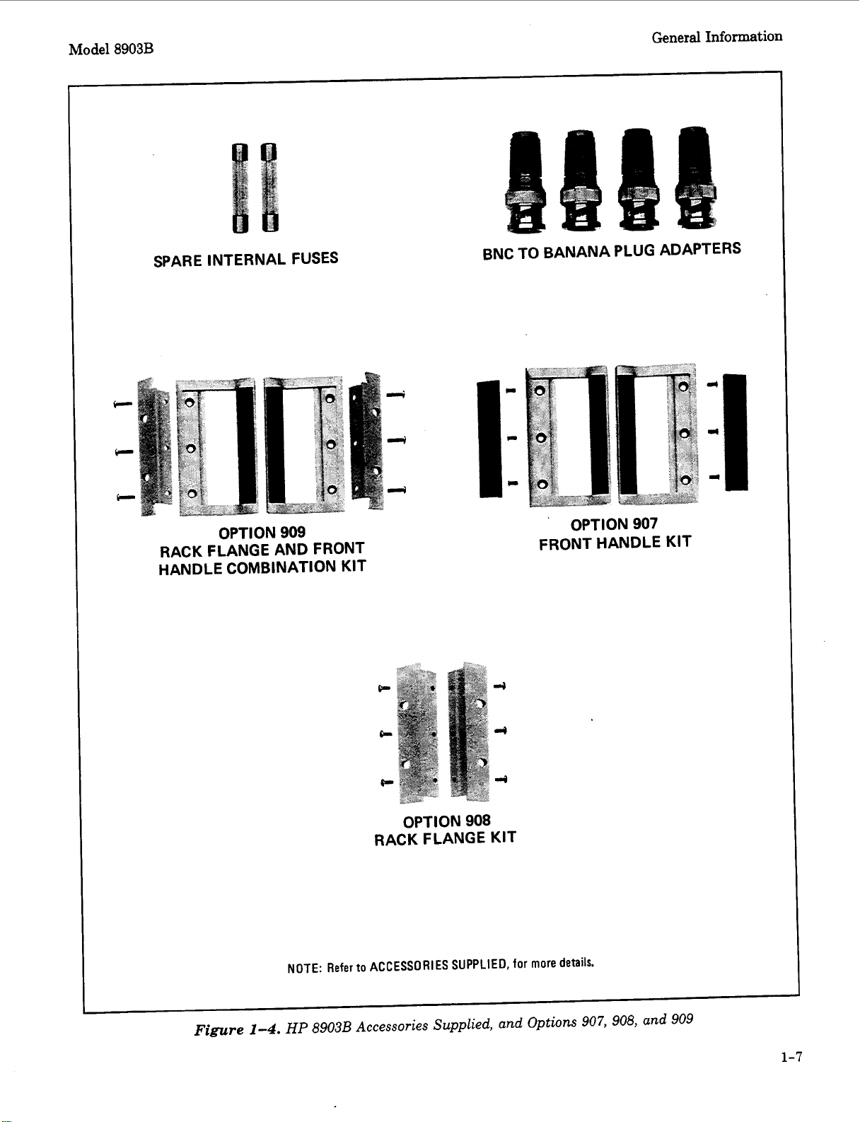
options are shown in Figure 1-4.
Front Handle Kit (Option
907).
Ease of handling
is
increased with the front-panel handles. Order
HP
part number 5061-9689.
Rack Flange
Kit
(Option
908).
The Audio Analyzer can be solidly mounted to an instrument rack
using the flange kit. Order HP part number 5061-9677.
Rack Flange and Front Handle Combination Kit (Option 909).
This
is
not a front handle kit and
a rack flange kit packaged together; it is composed of
a
unique part which combines both functions.
Order
HP
part number 5061-9683.
1-6
General Information
Model
8903B
SPARE INTERNAL FUSES
BNC TO BANANA PLUG ADAPTERS
OPTION
909
RACK FLANGE AND FRONT
HANDLE COMBINATION KIT
’
OPTION907
FRONT HANDLE KIT
OPTION
908
RACK FLANGE KIT
NOTE:
Refer
to
ACCESSORIES
SUPPLIED,
for
more
details.
Figure
1-4.
HP
8903B Accessories Supplied, and Options
907,
908, and 909
1-7

General Information Model 8903B
1-8.
HEWLETT-PACKARD INTERFACE BUS
Compatibility
The Audio Analyzer is compatible with HP-IB to the extent indicated by the following code: SH1,
AH1,
T5,
TEO, L3, LEO,
SR1,
RL1, PPO, DC1, DT1,
CO,
El.
The Audio Analyzer interfaces with the
bus via open collector TTL circuitry. An explanation of the compatibility code can be found in IEEE
Standard 488,
IEEE Standard Digital Interface for Programmable Instrumentation
or the identical
ANSI Standard MC1.l.
For
more detailed information relating to programmable control of the Audio
Analyzer, refer to
Remote Operation, Hewlett-Packard Interface
Bw
in Section 3 of this manual.
Selecting the HP-IB Address
The HP-IB address switches are located within the Audio Analyzer. The switches represent a five-
bit binary number. This number represents the talk and listen address characters which an HP-IB
controller is capable of generating. In addition,
two
more switches allow the Audio Analyzer to be set
to talk only
or
listen only.
A
table in Section 2 shows all HP-IB talk and listen addresses. Refer to
HP-IB
Address Selection
in Section 2
of
this manual.
1-9.
ACCESSORIES SUPPLIED
The accessories supplied with the Audio Analyzer are shown in Figure
1-4.
Fast
blow fuses with
a
1.5A rating for 100/120 Vac operation (HP 2110-0043) and a
1.OA
rating for
220/240 Vac operation (HP 2110-0001) are supplied. One fuse is installed in the instrument at the
time of shipment. The rating of the installed fuse is selected according to the line voltage specified by
the customer.
If
the voltage
is
not specified, the rating of the installed fuse will be selected according
to the country of destination.
Four type BNC-to-banana-plug adapters (HP 1250-2164) are also supplied for use when double-ended
inputs
or
outputs are desired. The conductor of the banana connector is connected to the center
conductor of the BNC connector adapted to. These adapters are used when the front-panel INPUT
or
OUTPUT FLOAT switches are set to FLOAT.
1-1
0.
ELECTRICAL EQUIPMENT AVAILABLE
(Also refer to Service Accessories, Table
1-4.)
HP-I6
Controllers
The Audio Analyzer has
an
HP-IB interface and can be used with any HP-IB compatible computing
controller
or
computer for automatic systems applications.
Front-to-Rear-Panel Connectors Retrofit Kit
This kit contains all the necessary components and full instructions for converting instruments with
front-panel connections for INPUT and OUTPUT HIGH and LOW to rear-panel connections.
For
serial prefixes 2730A and below, order
HP
part number 08903-60171. For serial prefix 2742A and
above, order HP part number 08903-60199. After installation and calibration, performance will be
identical to the
HP
8903B Option 001.
Rear-to-Front-Panel Connectors Retrofit Kit
This kit contains all the necessary components and full instructions for converting instruments with
rear-panel connections for INPUT and OUTPUT HIGH and
LOW
to front-panel connections. For
serial prefix 2730A and below order HP part number 08903-60172.
For
serial prefix 2742A and above,
order HP part number 08903-60200. After installation and calibration, performance will be identical
to the standard HP 8903B.
1-8
rev.26JU.9
Model
8903B
1-1
1.
MECHANICAL EQUIPMENT AVAILABLE
General Information
Chassis
Slide
Mount Kit
This kit
is
extremely useful when the Audio Analyzer
is
rack mounted. Access
to
internal circuits and
components
or
the rear-panel
is
possible without removing the instrument from the rack. Order HP
part number
1494-0060
for
431.8
mm
(17
in.) fixed slides and part number
1494-0061
for the correct
adapters for non-HP rack enclosures.
Chassis Tilt
Slide
Mount Kit
This kit
is
the same as the Chassis Slide Mount Kit above except
it
also allows the tilting of the
instrument up
or
down
90".
Order HP part number
1494-0062
for
431.8
mm
(17
in.) tilting slides and
part
number
1494-0061
for
the correct adapters for non-HP rack enclosures.
OIFFERENTIAL-
OVER- TO-SINGLE- PROGRAMMABLE
AC/OC
INPUT
VOLTAGE ENOEO- GAIN
ATTFTOR
PROTECTION
AMPLICIER AMPLIFIER
IN^
c>-
HIGH
I" I
-
-
OVFII-
I
I
%?
ACfOC
VOLTAGE
PROTECTION
INTERNAL
PLUG-IN
HP/BP
PROGRAMMABLE PROGRAMMABLE
MONITOR
FILTER
!t
1I
VOLTAGE-
TO-TIME
CONVERTER
SINAO METER
-0
RB8giE;o
..--
0
KEYBOARO AN0 OISPLAY
2
rn
a8
ooDD
D
w..
-P
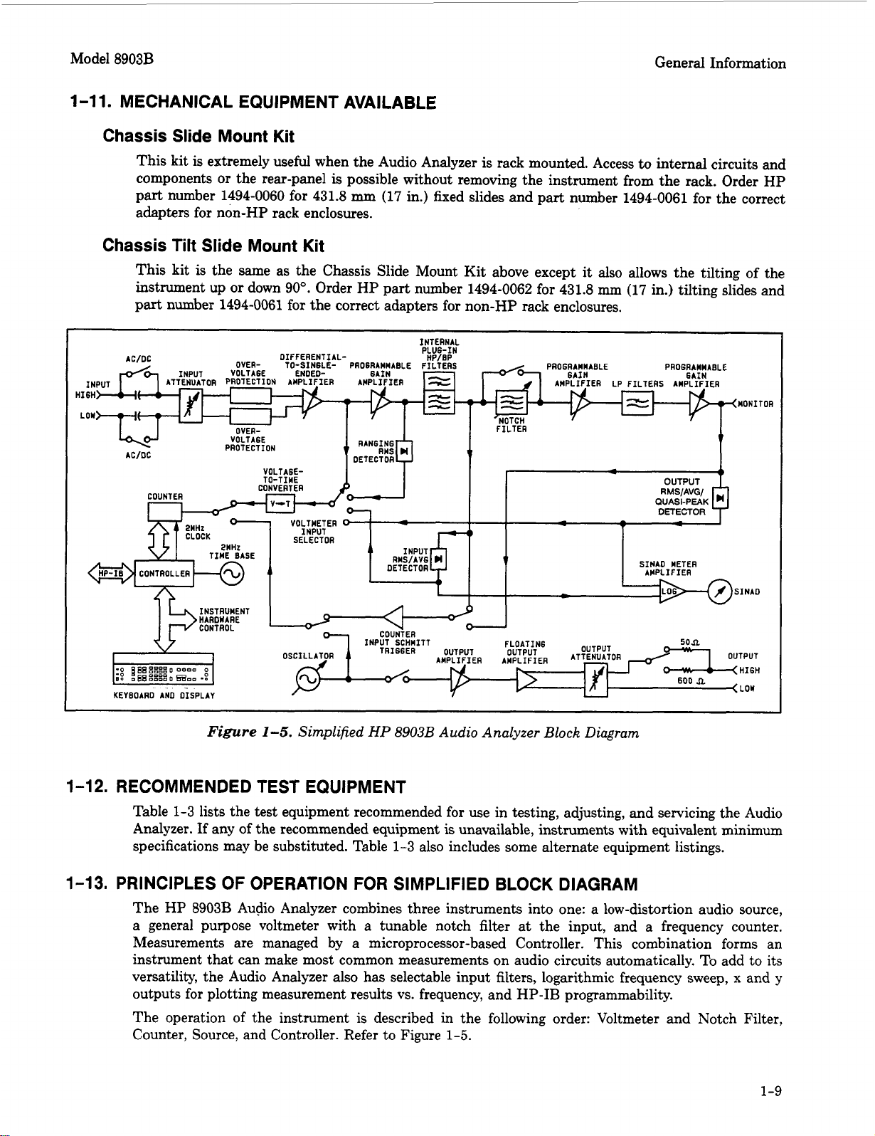
Figure
1-5.
Simplified
HP
8903B
Audio Analyzer
Block
Diagram
1-12.
RECOMMENDED TEST EQUIPMENT
Table
1-3
lists the test equipment recommended for use in testing, adjusting, and servicing the Audio
Analyzer.
If
any of the recommended equipment
is
unavailable, instruments with equivalent minimum
specifications may be substituted. Table
1-3
also includes some alternate equipment listings.
1-13.
PRINCIPLES OF OPERATION FOR SIMPLIFIED BLOCK DIAGRAM
The HP
8903B
Audio Analyzer combines three instruments into one: a low-distortion audio source,
a general purpose voltmeter with
a
tunable notch filter at the input, and a frequency counter.
Measurements are managed by a microprocessor-based Controller. This combination forms an
instrument that can make most common measurements on audio circuits automatically. To add to its
versatility, the Audio Analyzer also has selectable input filters, logarithmic frequency sweep,
x
and
y
outputs
for
plotting measurement results vs. frequency, and HP-IB programmability.
The operation
of
the instrument
is
described in the following order: Voltmeter and Notch Filter,
Counter, Source, and Controller. Refer to Figure
1-5.
1-9
General Information Model
8903B
Voltmeter
and
Notch
Filter
The amplitude measurement path flows from the INPUT connectors (HIGH and LOW) to the MONI-
TOR output (on the rear panel) and includes the Input RM$/Average and Output RMS/Average/Quasi-
Peak Detectors, dc voltmeter (the Voltage-to-Time Converter and Counter), and SINAD meter circuitry.
Measurements are made on the difference between the signals at the HIGH INPUT connector and the
LOW INPUT connector
(or
ground). Differential and common-mode levels can be as high as 300V.
Signals that are common to both the HIGH and LOW connectors are balanced out.
The input signal
is
ac coupled for all measurement modes except dc level. The signal
is
scaled by the
Input Attenuator to
a
level of 3V
or
less. To protect the active circuits that follow, the Over-Voltage
Protection circuit opens whenever its input exceeds 15V. The differential signal
is
converted
to
a
single-ended signal (that is, a signal referenced to ground) and amplified. In the dc level mode, the dc
voltage
is
measured at this point by the dc voltmeter. The signal
is
further amplified by a Programmable
Gain Amplifier which
is
ac coupled. The gain
of
this amplifier and the Differential-to-Single-Ended
Amplifier are programmed to keep the signal level into the Input Detector and Notch Filter between
1.7
and
3
Vrms
to
optimize their effectiveness and accuracy, particularly in the distortion and SINAD
modes.
The output from the first Programmable Gain Amplifier is converted to dc by the Ranging RMS
Detector and measured by the dc voltmeter. The output of this detector is used to set the gain of
the input circuits. The signal then passes through the
HP/BP
filters to the Input RMS/Average
Detector and becomes the numerator of the SINAD measurement and the denominator of the distortion
measurement (refer to
Basics
of
Audio Measurements).
The Input RMS/Average Detector
is
not used
to make the ac level measurement; the Output RMS/Average/Quasi-peak Detector is used for this
measurement. For dc level measurements, the Ranging RMS Detector also monitors the ac component
(if there
is
one) and lowers the gain of the input path
if
the signal will overload the input amplifiers;
otherwise, the gain of the input path is determined by measuring the dc level.
At
this point, one of the
two internal plug-in filters can be inserted into the signal path. The
400
Hz high-pass filter
is
usually
used to suppress line hum
or
the low frequency squelch tone used on some mobile transceivers. The
weighting filters have bandpass frequency responses that simulate the “average” response of human
hearing. In the SINAD, distortion, and distortion level modes, the frequency of the input signal is
counted at the output of the internal plug-in HP/BP Filters.
When measuring SINAD, distortion,
or
distortion level, the fundamental of the signal is removed by
the Notch Filter. The output from the filter
is
the distortion and noise of the signal. In the ac level
and signal-to-noise ratio modes the Notch Filter
is
bypassed. After amplifying and low-pass filtering,
the output from the Notch Filter is converted to dc by the Output RMS/Average/Quasi-peak Detector
and measured by the dc voltmeter.
When measuring distortion
or
distortion level, the Notch Filter
is
automatically tuned to the frequency
counted at the input to the filter. Coarse tuning
is
via the Controller. Fine tuning and balance are via
circuitry internal to the Notch Filter. When measuring SINAD, the Notch Filter
is
coarse tuned by
the Controller to the same frequency as the internal source. Thus, a SINAD measurement
is
normally
only made with the internal source as the stimulus and permits measurements in the presence
of
large amounts of noise (where the Controller would be unable to determine the input frequency).
If
an
external source
is
used in the SINAD measurement mode, the source frequency must be within
5%
of
the frequency of the internal source. The
two
Programmable Gain Amplifiers, following the Notch
Filter, amplify the low-level noise and distortion signals from the Notch Filter. The overall gain of the
two amplifiers is normally set to maintain a signal level of
0.3
to 3V at the MONITOR output.
The 30 kHz and
80
kHz LP Filters are selected from the Keyboard. With no low-pass filtering,
the
3
dB
bandwidth of the measurement system is approximately
750
kHz. The filters are most
often used to remove the high-frequency noise components in low-frequency SINAD and distortion
measurements. The output from the second Programmable Gain Amplifier drives the rear-panel
MONITOR output connector. The frequency of this signal
is
also measured by the Counter in the
ac
level
and signal-to-noise ratio measurement modes because of the increased sensitivity at this point.
The Output Detector is read by the dc voltmeter in the ac level, SINAD (the denominator), distortion
(the numerator), distortion level, and signal-to-noise ratio measurement modes.
It
is also used to set the
1-10
Model
8903B
General Information
gain
of
the
two
Programmable Gain Amplifiers. Both the input and output detectors can be configured
via special functions to respond to the absolute average of the signal instead
of
the true
rms
value.
In the SIN AD mode the outputs from the Input RMS/Average and Output RMS/Average/Quasi-peak
Detectors are converted to a current representing the log of the ratio
of
the
two
signals by the SINAD
Meter Amplifier
to
drive the SINAD panel meter. Since SINAD measurements are often made under
very noisy conditions, the panel meter makes
it
easier
to
average the reading and to discern trends.
The Voltage-to-Time Converter converts the dc inputs into a time interval which
is
measured by the
Counter. The Output Detector can also be configured via special functions to respond
to
the quasi-peak
of the signal. This type of detector
is
designed
to
respond to impulse type signals better than other
types. The Quasi-peak Detector has a fast rise time coupled with a slow decay time constant which
“captures” impulses
or
other
signals
with a high crest factor (noise
or
repetitive signal bursts).
Counter
The Counter
is
a reciprocal counter. To measure frequency, it counts the period of one
or
more cycles
of the signal at
its
input, then the Controller divides the number of periods by the accumulated count.
The reference
for
the Counter is the
2
MHz Time Base which also is the clock for the Controller. The
Counter has four inputs and three modes of operation:
Voltage Measurement.
The time interval from the Voltage-to-Time Converter
is
counted. The
accumulated count is proportional
to
the dc voltage.
For
direct measurements (ac level, dc level,
and distortion level), the count
is
processed directly by the Controller and displayed on the right
display. For ratio measurements (SIN
AD,
distortion, and signal-to-noise), the counts
of
two
successive
measurements are processed and displayed. For SINAD and distortion, the ratio of the output of the
Input RMS/Average Detector and Output RMSIAveragejQuasi-Peak Detector
is
computed. For signal-
to-noise, the ratio of
two
consecutive outputs from the Output RMS/Average/Quasi-peak Detector is
computed. One output is with the Oscillator on, the other is with the Oscillator
off.
Input Frequency Measurement.
The signal from the last Programmable Gain Amplifier or the HP/BP
Filters is conditioned by the Counter Input Schmitt Trigger to make it compatible with the Counter’s
input. The period of the signal is then counted, the count
is
processed by the Controller, and the
frequency is displayed on the left display.
Source Frequency Measurement.
The Counter measures the frequency
of
the internal source only
when the Oscillator
is
being tuned. The frequency is normally not displayed. To make a measurement
of the source frequency, the output
of
the Oscillator is fed
into
the Counter, the period measured,
and
the result processed by the Controller.
Source
The source covers the frequency range from
20
Hz
to
100
kHz.
It is tuned to the frequency entered
from Keyboard by the Controller using a tune-and-count routine. (Note that the frequency is not
obtained by frequency synthesis.) The switch following the Oscillator is normally closed except in the
signal-to-noise ratio measurement mode
or
when an amplitude of OV
is
entered from the Keyboard.
The output from the Oscillator
is
approximately
3V.
The Output Amplifier sets the source output level in fine steps. The Floating Output Amplifier converts
the single-ended input into a floating signal (either output can be grounded
or
floated up to
1OV
peak).
The Output Attenuator sets the output level in coarse steps. The maximum signal to the OUTPUT
connectors is 6V into an open circuit
or
3V into the matching termination. The output impedance of
the source is
HP-IB
programmable to either
50
or
600R. (The keyboard-selected level
is
the open-circuit
level.)
1-11
General Information Model
8903B
Controller
The entire operation of the instrument is under control of a microprocessor-based Controller. The
Controller sets up the instrument at turn-on, interprets Keyboard entries, executes changes
in
mode
of operation, continually monitors instrument operation, sends measurement results and errors to the
front-panel displays, and interfaces with HP-IB. In addition, its computing capability
is
used
to
simplify
circuit operation.
For
example, it forms the last stage of the Counter, converts measurement results
into ratios (in
’3%
or
dB),
etc. It also contains routines useful for servicing the instrument.
1-14.
BASICS
OF
AUDIO MEASUREMENTS
The “audion frequency range is usually taken to be from
20
Hz to
20
kHz. Few people have hearing
that good, but the term is a convenient one to describe sub-RF frequencies encountered in electronics.
The frequency range of the Audio Analyzer extends beyond the audio range
to
include fundamentals
up
to
100
kHz.
Electronic instrumentation provides most of the tools for quantitative analysis of audio signals. Thus,
if
the signal is non-electrical (for example, mechanical
or
acoustic),
it
must be converted
to
an electrical
signal by a transducer of some kind (for example, strain gauge or microphone) before
it
can be analyzed.
Apart
from attentive listening
to
a hi-fi system, the most intuitive way of analyzing an electrical signal
in the audio range
is
visually with an oscilloscope. Here you get a feeling for the signal’s size (loudness),
frequency (pitch), and shape (timbre). You can also determine
if
these parameters change with time
or
are stable, and you can even make some quantitative measurements on it (for example, peak level, dc
offset, period, risetime, etc.). Many times, however, the parameter sought does not lend itself
to
easy
visual analysis. Thus, the Audio Analyzer was designed.
It
combines into one instrument a series of
general and specialized instruments, under microprocessor control, that make it easy for you to obtain
accurate, quantitative measurements on audio signals of any general waveshape.
AC
Level
Consider the very common measurement of a signal’s ac rms level. To make this measurement with
an oscilloscope, you must first decide the nature of the signal, because from it, the relationship of the
peak level to the
rms
level can be mathematically determined. If the signal is sinusoidal, for example,
the rms value
is
the peak amplitude divided by
a.
This measurement is greatly simplified with a rms voltmeter which electronically measures the rms
level and displays the result. However, no other information about the signal is provided. The Audio
Analyzer contains both an rms- and an average-responding voltmeter. The
rms
level of the signal
is
displayed whenever the AC
LEVEL
mode is selected. The average level can be displayed by entering
5.2
SPCL. The quasi-peak level can be displayed by entering
5.7
SPCL.
A
special function
is
also provided
which converts the measurement result into watts for
a
specified (external) load resistance.
Another important ac signal characteristic
is
the variation in level vs. frequency (flatness). Of course
you can easily set a reference level (such as
1V)
at a particular frequency (such
as
1
kHz) and monitor
the change in level as the input frequency is changed. (The source’s level
is
assumed
to
be flat; otherwise,
it
too
must be checked.) The Audio Analyzer makes this measurement easier in three ways. First, the
analyzer contains a flat, wide-range oscillator that can be used as the stimulus. Second, the reference
can be set to
100%
or
0
dB
by the press of a button (the RATIO key). Third, the measurement can be
automatically swept and the results can be plotted by connecting an x-y recorder to the (rear-panel)
X AXIS and
Y
AXIS outputs.
An additional parameter related to ac level is gain, and more often, gain vs. frequency. To make a gain
measurement, measure the input to the device, then the output, and take the ratio. This measurement
is
made easier by the Audio Analyzer when used with
its
internal oscillator. You
first
key in the desired
input level, then either measure
it
and set it as a reference (press RATIO)
or
key in the
level
as the
ratio reference. Then measure the output. The result can be expressed in either
’%
or
dB.
If desired,
the input can be swept and the gain plotted
as
a function of frequency (since the frequency plots
logarithmically, the result
is
a Bode magnitude plot if
dJ3
is
used).
1-12
Model
8903B
General Information
Frequency
Another common and basic measurement
is
frequency. With an oscilloscope, you simply determine the
time interval between like points on the repetitive waveform and take the reciprocal. With
a
frequency
counter, frequency
is
measured electronically and displayed. The measurement
is
easier and usually
much more accurate than could be made visually with an oscilloscope.
The Audio Analyzer contains
a
counter which displays the frequency of the input signal for all ac
measurements.
It
should be noted that the counter
is
a reciprocal type; it measures the period
of
the signal (as you do with an oscilloscope) and computes the reciprocal
to
obtain the frequency. The
advantage of this technique
is
that for low (audio) frequencies, higher resolution
is
obtained in a shorter
measurement time.
DC
Level
Although not part of an audio signal, dc level
is
a quantity often encountered in audio equipment (for
example, bias voltages and outputs from ac-to-dc converters). Sometimes plots of dc level vs. frequency
are desired
(as
in the case of
an
ac-to-dc converter).
The Audio Analyzer has dc level as one of
its
measurement modes.
Signal Impurities
Distortion, SINAD, and signal-to-noise ratio are used to describe the impurity content of a signal.
These terms are somewhat related and
can
often be confused.
A
pure signal
is
defined
as
a perfect
sinusoid, that
is,
one whose frequency spectrum contains only a single spectral component. Impurities
are not always undesirable. Impurities, for example, are what add character
to
the sound of musical
instruments. Pure
signals
in music sound monotonous. However, when testing a linear audio system,
if
a pure signal is applied
to
the input, anything but a pure signal at the output indicates that the system
is
degrading the signal. There are several common classifications of impurities: harmonic distortion
(harmonics of the fundamental), intermodulation distortion (beat signals of
two or
more non-related
signals), noise (random signals), and spurious signals (for example, line hum and interference). All but
intermodulation distortion are easily measured by the Audio Analyzer.
Distortion
Harmonic distortion on a spectrally pure signal is created by non-linearities in the circuit through
which
it
passes. The non-linearities can arise in the transfer characteristics of the active devices
or
by
running the active device into saturation
or
cutoff. Often, distortion can be reduced by reducing the
signal level, filtering,
or
adding negative feedback.
According to Fourier mathematics, the non-linear terms in the circuit’s transfer function give rise
to
harmonics of the signal. Total harmonic distortion (THD) is usually defined
as
the ratio of the rms
sum of the harmonics to the rms level of the fundamental. The ratio
is
usually converted
to
7%
or
dB.
An oscilloscope gives only a rough indication of the amount of distortion present on a signal.
A
general
rule of thumb is that if the non-linearity causing the distortion
is
“gentle” (for example, not clipped),
a trained eye can discern distortion as low a
5%
on an oscilloscope display. Figure
1-6
shows several
examples of waveforms with
5%
THD and the components that combined
to
produce them.
(5%
distortion would be considered quite high in
a
quality hi-fi amplifier.)
An audio spectrum analyzer, which allows the user to see the magnitude of all harmonics,
is
perhaps
the best instrument to measure harmonic distortion. The audio spectrum analyzer method, however,
requires a fairly expensive instrument and some mathematical manipulation.
1-13
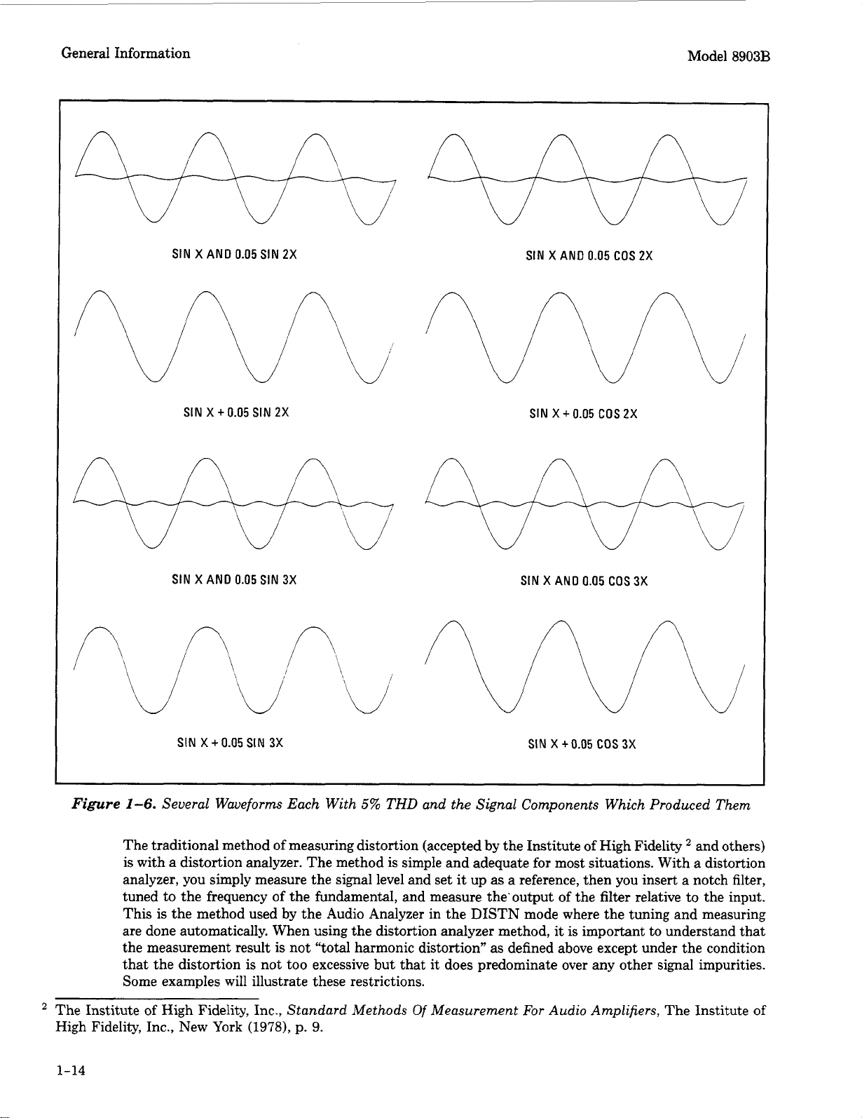
General Information Model
8903B
SIN
X
AND
0.05
SIN
2X
SIN
X
AND
0.05
COS
2X
SIN
X
+
0.05
SIN
2X
SIN
X
+
0.05
COS
2X
SIN
X
AND
0.05
SIN
3X
SIN
X
AND
0.05
COS
3X
SIN
X
+
0.05
SIN
3X
SIN
X
+
0.05
COS
3X
Figure
1-6. Several Waveforms Each With
5%
THD
and the Signal Components Which Produced Them
The traditional method
of
measuring distortion (accepted by the Institute of High Fidelity and others)
is
with a distortion analyzer. The method
is
simple and adequate for most situations. With a distortion
analyzer, you simply measure the signal level and set
it
up
as
a reference, then you insert a notch filter,
tuned to the frequency
of
the fundamental, and measure the’output of the filter relative to the input.
This is the method used by the Audio Analyzer in the DISTN mode where the tuning and measuring
are done automatically. When using the distortion analyzer method,
it
is
important to understand that
the measurement result
is
not “total harmonic distortion” as defined above except under the condition
that the distortion is not too excessive but that it does predominate over any other signal impurities.
Some examples will illustrate these restrictions.
The Institute of High Fidelity, Inc., Standard Methods
Of
Measurement
For
Audio Amplifiers,
The
Institute
of
High Fidelity, Inc., New
York
(1978),
p.
9.
1-14
Model
8903B
General Information
Consider the case of excessive harmonic distortion. Let us use the example of a signal with 10% actual
total harmonic distortion in which all the distortion comes from the second harmonic. The second
harmonic
is
then 20
dJ3
below the fundamental as viewed on
a’
spectrum analyzer. When this signal
is
measured by a distortion analyzer, an error results from the first part of the measurement (measuring
the input level) because the input level is not quite the same
as
the level of the fundamental.
If
the fundamental level were
1
Vrms, the second harmonic level would be
0.1
Vrms (one-tenth of the
fundamental). The total input level (measured with a true rms voltmeter)
is
the rms sum of the
two
components, namely,
Input
=
,/(1)2
+
(0.1)2
=
1.005V
or
0.5% high. Thus, the measurement result would be 9.95% distortion instead of the true 10%. Actually
you can see that the distortion must really be excessive to affect the measurement significantly.
Now consider the case where other types of impurities are significant. Suppose the actual total harmonic
distortion
is
1%
but that there is an additional hum component that has
a
level
1%
of
the fundamental
level. The distortion measured by a distortion analyzer will be 1.4% (that is, 40%
or
3
dB
high). How,
then, can you be sure that the result is a valid measurement of distortion? One way
is
to observe the
(rear-panel) MONITOR output with an oscilloscope. If the waveform
is
clean and harmonically related
to the fundamental, the measurement
is
actual total harmonic distortion.
If
it
is not, selectable filters
are provided to remove unwanted signals. Use the optional 400 Hz High-Pass Filter
to
remove line
hum. Use the
30
kHz
or
80
kHz Low Pass Filter
to
remove out-of-band noise. However, select only
filters that do not affect the fundamental and the harmonics of interest. Sometimes
it
is
desired to
include hum and noise as part of the “distortion” measurement. For this reason, the measurement
is
often referred to as a THD
+
N (total harmonic distortion plus noise) measurement.
SINAD
For most practical purposes the SINAD measurement, as made by the Audio Analyzer,
is
equal
to
the
reciprocal of the distortion measurement.
It
is usually expressed in
dB.
The one subtle distinction
is
that the notch filter
is
coarsely programmed to the frequency of the internal source (but fine tuned to
the signal at its input). This permits measurements in the presence of large amounts of impurities and
assures that the fundamental is tuned out.
If
an external source is used,
it
must be within 5%
of
the
frequency setting of the internal source.
SINAD is an acronym for SIgnal, Noise, And Distortion. The ratio (normally expressed in
dB)
computed in the
SINAD
measurement
is
rms value
of
signal, ndse and distortion
rms value
of
ndse and distortion
SINAD
=
20
log
The equation eliminates the
two
restrictions discussed in connection with the distortion measurement.
SINAD is used most often in determining the sensitivity of a receiver. Receiver sensitivity
is
defined
as the RF level that, when modulated in a specified manner with a pure audio tone, creates a certain
SINAD (usually 10
or
12
dB)
at the receiver’s audio output. (The tone can just be discerned in the
noise.) Sometimes a psophometric (that is, noise measuring) filter is required in the receiver sensitivity
measurement. Optional plug-in weighting filters modify the frequency response of the Audio Analyzer
with a bandpass characteristic that approximates the response of human hearing. Weighting filters
which meet most international standards are available.
Signal-to-Noise Ratio
Measurement of the signal-to-noise ratio requires the use of the Audio Analyzer’s internal source. The
Audio Analyzer simply turns the source (set to a specified level) on and
off
and measures the ac level
for both conditions. This
is
similar to the experience you have when listening to a recording at a
comfortable volume, then lifting the tone arm and listening to the level
of
the residual hiss and hum.
1-15
General Information
Model 8903B
Internal Source
The internal source
is
used when a low-distortion stimulus
for
the device under
test
is
desired. Its
distortion
is
about the same
as
that
of
the
Audio
Analyzer’s measurement system. The combination
permits measurements
of
distortion
as
low as
0.003%
(-90
dB).
Plotting
When used in conjunction with the sweep mode, any of the measurements vs. frequency can be plotted
using
the rear-panel
X
and
Y
AXIS outputs and
an
x-y recorder. The internal source is used as the
stimulus. This simplifies traditionally time consuming measurements such as flatness, gain, distortion,
and SINAD vs. frequency,
and
does not require the use
of
an external controller (although this
too
can
be used via HP-IB).
1-16
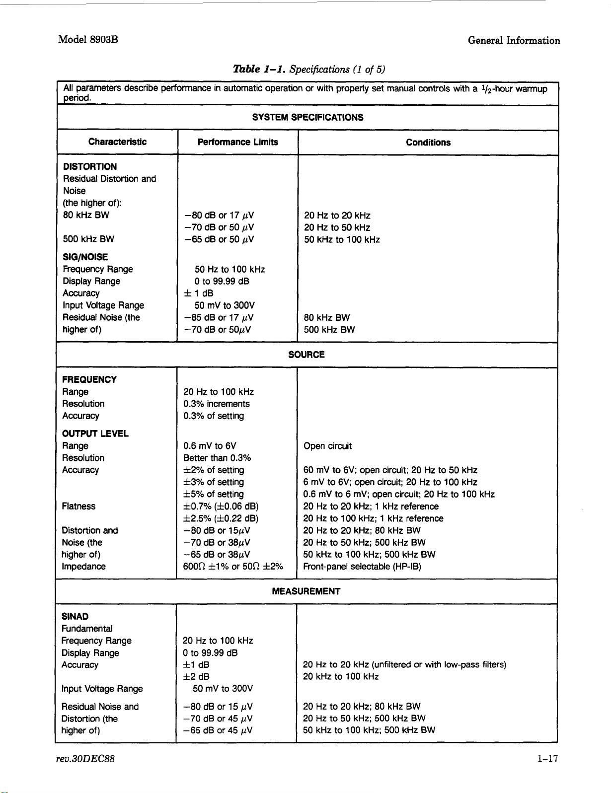
Model
8903B
General Information
lhble
1-1.
Specifications
(1
of
5)
All parameters describe performance in automatic operation or with properly set manual controls with a 1/2hour warmup
period.
SYSTEM SPECIFICATIONS
I------
Characteristic
DISTORTION
Residual Distortion and
Noise
(the higher
of):
80 kHz BW
500
kHz BW
SIG/NOISE
Frequency Range
Display Range
Accuracy
Input Voltage Range
Residual Noise (the
higher of)
FREQUENCY
Range
Resolution
Accuracy
OUTPUT
LEVEL
Range
Resolution
Accuracy
Flatness
Distortion and
Noise (the
higher of)
Impedance
SlNAD
Fundamental
Frequency Range
Display Range
Accuracy
Input Voltage Range
Residual Noise and
Distortion (the
higher of)
Performance Limits
-80 dB or
17
pV
-70
dB or
50
pV
-65 dB or
50
pV
50
Hz to 100 kHz
0
to 99.99 dB
f
1
dB
50
mV to 300V
-85 dB or
17
pV
-70
dB or 50pV
20 Hz to
100
kHz
0.3% increments
0.3% of setting
0.6 mV to 6V
Better than 0.3%
f2%
of setting
f3% of setting
f5%
of setting
f0.7%
(f0.06
dB)
f2.570 (f0.22
dB)
-80
dB or 15pV
-70
dB or 38pV
-65 dB or 38pV
6000
fl%
or
500
f2%
Conditions
20 Hz to
20
kHz
20
Hz to 50 kHz
50
kHz to 100 kHz
80 kHz BW
500 kHz BW
SOURCE
Open circuit
60 mV to 6V; open circuit;
20
Hz to
50
kHz
6 mV to
6V;
open circuit;
20
Hz to
100
kHz
0.6
mV to 6
rnV;
open circuit;
20
Hz to 100 kHz
20
Hz to
20
kHz; 1 kHz reference
20
Hz to
100
kHz; 1 kHz reference
20
Hz to
20
kHz; 80 kHz BW
20
Hz to
50
kHz;
500
kHz BW
50
kHz to
100
kHz; 500 kHz BW
Front-panel selectable
(HP-IB)
MEASUREMENT
20 Hz to 100 kHz
0 to 99.99 dB
fl
dB
f2
dB
50 mV
to
300V
-80 dB
or
15
pV
-70
dB or
45
pV
-65 dB or
45
pV
20 Hz to
20
kHz (unfiltered or with low-pass filters)
20
kHz to
100
kHz
20
Hz to
20
kHz; 80 kHz BW
20
Hz
to
50 kHz;
500
kHz
BW
50
kHz
to
100
kHz; 500 kHz BW
rev.
30DEC88
1-17
Loading...