

Page 1
Operation and Service
Guide
HP
Signal Generator
SERIAL NUMBERS
This manual applies directly to the following HP 8648 model/serial
prefix combinations and below:
HP
HP
HP
HP Part No. 08648-90048
Printed in USA April 1999
Supersedes: November 1998
Page 2

Notice. The information contained in this document is subject to
change without notice.
Hewlett-Packard makes no warranty of any kind with regard to this
material, including but not limited to, the implied warranties of
merchantability and fitness for a particular purpose. Hewlett-Packard
shall not be liable for errors contained herein or for incidental
or consequential damages in connection with the furnishing,
performance, or use of this material.
Copyright Hewlett-Packard Company 1996, 1998
All Rights Reserved. Reproduction, adaptation, or translation without
prior written permission is prohibited, except as allowed under the
copyright laws.
1400 Fountaingrove Parkway, Santa Rosa, CA 95403-1799, USA
FLEX and Motorola are trademarks of Motorola, Inc.
Windows@ and MS Windows@ are U.S. registered trademarks of
Microsoft Corporation.
Windows NT@ is a U.S. registered trademark of Microsoft
Corporation.
Page 3

Certification
Hewlett-Packard Company certifies that this product met its published
specifications at the time of shipment from the factory.
Packard further certifies that its calibration measurements are
traceable to the United States National Institute of Standards and
Technology, to the extent allowed by the Institute’s calibration facility,
and to the calibration facilities of other International Standards
Organization members.
Information
Warranty
Regulatory
The regulatory information is in Chapter 4, “Specifications.”
This Hewlett-Packard instrument product is warranted against defects
in material and workmanship for a period of one year from date of
shipment. During the warranty period, Hewlett-Packard Company
will, at its option, either repair or replace products which prove to be
defective.
For warranty service or repair, this product must be returned to a
service facility designated by Hewlett-Packard. Buyer shall prepay
shipping charges to Hewlett-Packard and Hewlett-Packard shall pay
shipping charges to return the product to Buyer. However, Buyer shall
pay all shipping charges, duties, and taxes for products returned to
Hewlett-Packard from another country.
Hewlett-Packard warrants that its software and firmware designated
by Hewlett-Packard for use with an instrument will execute its
programming instructions when properly installed on that instrument.
Hewlett- Packard does not warrant that the operation of the
instrument, or software, or firmware will be uninterrupted or
error-free.
LIMITATION OF WARRANTY
The foregoing warranty shall not apply to defects resulting from
improper or inadequate maintenance by Buyer, Buyer-supplied
software or interfacing, unauthorized modification or misuse,
operation outside of the environmental specifications for the
product, or improper site preparation or maintenance.
NO OTHER WARRANTY IS EXPRESSED OR IMPLIED.
HEWLETT-PACKARD SPECIFICALLY DISCLAIMS THE IMPLIED
WARRANTIES OF MERCHANTABILITY AND FITNESS FOR A
PARTICULAR PURPOSE.
EXCLUSIVE REMEDIES
THE REMEDIES PROVIDED HEREIN ARE BUYER’S SOLE AND
EXCLUSIVE REMEDIES. HEWLETT-PACKARD SHALL NOT BE
LIABLE FOR ANY DIRECT, INDIRECT, SPECIAL, INCIDENTAL, OR
CONSEQUENTIAL DAMAGES, WHETHER BASED ON CONTRACT,
TORT, OR ANY OTHER LEGAL THEORY.
. . .
Page 4

Assistance
maintenance
are available for
Refer
gour
list of
and
and
customer
$br
and
following
Page 5
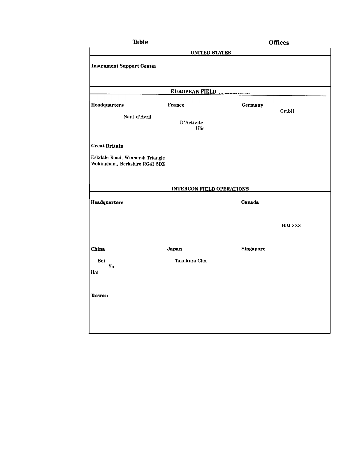
O-l. Hewlett-Packard Sales and Service
Hewlett-Packard Company
(800) 403-0801
Hewlett-Packard S.A. Hewlett-Packard France
150, Route du Nant-d’Avril 1 Avenue Du Canada
12 17 Meyrin O/Geneva
Switzerland F-91947 Les
(41 22) 780.8111 France
Hewlett-Packard Ltd.
,
England
(44 734) 696622
Hewlett-Packard Company
3495 Deer Creek Road
Palo Alto, California, USA
94304-1316
(415) 857-5027
Support
Zone D’Activite De Courtaboeuf 61352 Bad Homburg v.d.H
Cedex
(33 1) 69 82 60 60
Australia
Hewlett-Packard Australia Ltd.
31-41 Joseph Street
Blackburn, Victoria 3130
(61 3) 895-2895 Kirkland, Quebec
OPERATIONS
Hewlett-Packard
Hewlett-Packard Strasse
Germany
(49 6172) 16-O
Hewlett-Packard (Canada) Ltd.
17500 South Service Road
Trans-Canada Highway
2X8
Canada
(514) 697-4232
China Hewlett-Packard Company Hewlett-Packard Japan, Ltd.
38
San Huan Xl Road
Shuang
Beijing, China
(86 1) 256-6888
Hewlett-Packard Taiwan
8th Floor, H-P Building
337 Fu Hsing North Road
Taipei, Taiwan
(886 2) 712-0404
Shu Tokyo 192, Japan
Dian District (81 426) 60-2111
9-l
Hachioji
Hewlett-Packard Singapore (Pte.) Ltd.
150 Beach Road
#29-00 Gateway West
Singapore 0718
(65) 291-9088
V
Page 6
Safety Notes
The following safety notes are used throughout this manual.
Familiarize yourself with each of the notes and its meaning before
operating this instrument.
Caution
Warning
Instrument Markings
Caution denotes a hazard. It calls attention to a procedure that, if
not correctly performed or adhered to, would result in damage to or
destruction of the instrument. Do not proceed beyond a caution sign
until the indicated conditions are fully understood and met.
Warning denotes a hazard. It calls attention to a procedure
which, if not correctly performed or adhered to, could result in
injury or loss of life. Do not proceed beyond a warning note until
the indicated conditions are fully understood and met.
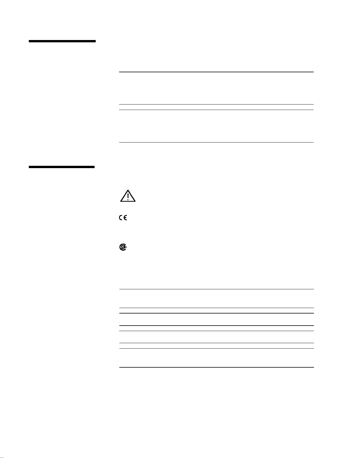
The following markings and caution and warning labels are used on
the instrument. Be sure to observe all cautions and warnings.
!
The instruction documentation symbol. The product is
marked with this symbol when it is necessary for the user
to refer to the instructions in the manual.
The CE93 mark shows compliance with the European
Community 1993 standards.
Warning
Warning
Warning
Caution
The CSA mark is the Canadian Standards Association
safety mark.
“ISMl-A” This is a symbol of an Industrial Scientific and Medical
Group 1 Class A product.
Hazardous voltage always present in this area with instrument
power cord connected to ac line.
Do not remove this screw when removing cover from instrument.
Hazardous Voltage
Hazardous electrical shock. Heat sink is live. Disconnect power
supply before servicing.
vi
Page 7

General Safety Considerations
Warning
Warning
Warning
Caution
No operator serviceable parts inside. Refer servicing to qualified
personnel.
If this instrument is used in a manner not specified by
Hewlett-Packard Co., the protection provided by the instrument
may be impaired.
For continued protection against fire hazard replace line fuse
only with same type and rating (3 A 250 V type F). The use of
other fuses or material is prohibited.
Always use the three-prong ac power cord supplied with this
instrument. Failure to ensure adequate earth grounding by not using
this cord may cause instrument damage.
prevent electrical shock, do not remove covers.
vii
Page 8

How to Use This Guide
This guide uses the
following convention:
Documentation
Description
KEY] This represents a key physically located on
the instrument.
Display
This font is used to represent text which
appears on the instrument display.
This guide contains the information required to operate, calibrate, and
repair the signal generator to the assembly level. Included are the
following:
n a quick overview of the signal generator
n examples of typical operation
n a reference section that describes all operation features
n explanations of error messages displayed on the signal generator
n installation instructions
tables of specifications
n tables of post-repair information and recommended equipment
required
n theory of operation of the signal generator
n troubleshooting procedures to identify failed assemblies
n disassembly procedures for removal and replacement of assemblies
n replaceable part numbers
n adjustments required after repair or performance test failure
n performance tests to test the instrument to specifications
n supplemental verification tests to test some unspecified parameters
of the instrument
. . .
Page 9

Contents
1. Operation
Quick Overview ...................
1. Power Key ...................
2. Display .....................
3. Function and Data Keys
4. Increment Set Keys
5. Knobs. .....................
6. MEMORY
Modulation Source
la. Operation Examples
Getting Started ....................
Operation Examples
Setting the RF Output Signal
Setting the Frequency
Setting the Amplitude
Turn on the RF Output
Setting the Modulation
Incrementing or Decrementing the RF Output Signal
Preliminary Steps ..................
Using the Knob ...................
Using the Increment keys
Using the Memory Registers
Saving Instrument Settings in Register Sequences
Selecting the Sequence
Saving Settings in Registers
Checking the Sequence
Checking a Different Sequence
Deleting a Register from the Sequence
Selecting the Sequence
Deleting a Register
Renumbering the Registers in a Sequence
Decreasing the Register Number
Checking the Sequence
Inserting a Register in a Sequence
Saving a New Register
Offsetting the RF Output from a Reference
Setting the Reference Value
Offsetting the RF Output
Turning the Reference Mode Off or On
Setting a New Reference Value
Holding the Output Attenuator Range
Set the Amplitude Level
Holding the Attenuator
Adjusting the Amplitude
....................
................
................
................
.............
...............
.............
...............
...............
...............
...............
..............
..............
..............
............
..............
..........
........
..............
......
..........
..............
..........
..............
.......
.............
..............
.......
..........
.........
..............
...............
..............
. .
...
l-2
l-2
l-2
l-3
l-4
l-4
l-4
l-5
la-l
la-2
la-3
la-3
la-3
la-4
la-4
la-5
la-5
la-5
la-6
la-7
la-8
la-8
la-8
la-10
la-10
la-12
la-12
la-12
la-14
la-14
la-15
la-16
la-17
la-18
la-18
la-19
la-19
la-20
la-21
la-21
la-21
la-22
Contents-l
Page 10
Setting a User Selectable Modulated Frequency and
Waveform (Option
or
Only) ........
Setting the Modulation Level ............
Setting the Modulated Waveform ..........
Setting the Modulated Frequency ..........
Signaling a Numeric-Type FLEX Pager (Option
Setting Up Pager Encoding .............
Entering Pager Encoding Settings ..........
Selecting the Format Settings ............
Selecting the Data Rate and Pager Type Settings ...
Selecting the Message Settings ............
Selecting Transmission Repetitions and amplitude . .
Selecting the Pager
(Address) ........
Selecting the Protocol Settings ...........
Selecting the Roaming Mode Settings ........
Encoding ......................
lb. Operation Reference
Frequency and Amplitude ...............
1. Knob ......................
2. Digit-Select Arrow Keys .............
3. REFSET ....................
Units
4. REF
: : : : : : : : : : : : : : : : : :
Function .......................
1. FREQUENCY ..................
2. AMPLITUDE ..................
...................
Setting Up the Pager Encoder .............
1. ENCODER. ...................
Setting the Format .................
FLEX/FLEX-TD
..................
Setting the Data Rate and Pager Type .......
Setting the Message ................
Setting the Encoding Mode ............
Entering the Pager
(Address) .......
Setting the Protocol ...............
Setting the Roaming Mode ............
Message During Encoding .............
Signaling Examples ................
Roaming Example ............
POCSAG
......................
Setting the Data Rate and Pager Type .......
Setting the Message ................
Setting the Encoding Mode ............
Entering the Pager
(Address) .......
Message During Encoding .............
RESYNC.. ....................
Setting the Encoding Mode ............
Message During
..........
.......................
Setting the Data Rate ...............
Message During Encoding .............
SERVICE
......................
Setting the Data Rate . . . . . . . . . . . . . . . lb-35
Only)
la-23
la-23
la-24
la-24
la-25
la-26
la-27
la-27
la-28
la-29
la-29
la-30
la-31
1 a-32
la-32
lb-2
lb-2
lb-2
lb-3
lb-3
lb-3
lb-4
lb-4
lb-5
lb-5
lb-6
lb-7
lb-8
lb-9
lb-9
lb-12
lb-14
lb-16
lb-18
lb-19
lb-22
lb-23
lb-25
lb-27
lb-27
lb-29
lb-31
lb-32
lb-32
lb-33
lb-33
lb-33
lb-34
lb-34
lb-34
lb-35
Contents2
Page 11
Message During Servicing
Pulse Modulation ...................
1. PULSE .....................
Increment Set ....................
1.
START/STOP Encoding
PREV and NEXT
Data .........................
1. MHz/dBm kHz/mV
Units Conversion
ENTER
SHIFT
2. Backspace ....................
3. emf .......................
4.f ........................
Instrument Preset ..................
.....................
.....................
HP-IB
Memory .......................
Modulation Source ..................
RF Output ......................
Rear Panel ......................
Remote Interface (Accessory)
Memory Interface (Accessory)
........................
1. ADRS ......................
2. LOCAL .....................
l.SAV .......................
2. REG ......................
3. Register Recall Arrows
5. DEL ......................
Renumbering the Registers
1. MOD ON/OFF ..................
2.
3. (FREQUENCY) 4. (FREQUENCY/ WAVEFORM)
5. EXTACEXTDC
Setting the Modulation Level
7. MOD INPUT/OUTPUT
1. RF ON/OFF ...................
Vernier Ranges ..................
3. RF OUTPUT ...................
1. 10 MHz REF INPUT and OUTPUT
2. DISPLAY CONTRAST
3. AUXILIARY INTERFACE
4. Line Voltage Connector
5. HP-IB Connector
6.
7. External Pulse Input
1. MOD ON/OFF ..................
2. RF ON/OFF ...................
3. Sequence Selection Arrows
4. Register Recall Arrows
....................
.................
.................
.....................
......................
.....................
kHz
.................
................
.................
ADJ and Language Switches
.............
..............
..............
............
..............
...........
..............
...............
.............
.............
...............
.............
............
..............
.............
........
...
.........
......
lb-35
lb-36
lb-36
lb-38
lb-38
lb-38
lb-38
lb-39
lb-39
lb-39
lb-39
lb-39
lb-40
lb-40
lb-40
lb-41
lb-41
lb-41
lb-45
1 b-45
lb-45
lb-46
lb-47
lb-47
lb-48
lb-48
lb-49
lb-49
lb-50
lb-51
lb-51
lb-51
lb-52
lb-52
lb-53
lb-53
lb-54
lb-54
lb-54
lb-54
lb-55
lb-56
lb-56
lb-56
lb-56
lb-57
lb-57
lb-57
lb-57
lb-58
lb-58
lb-58
lb-58
lb-59
1 b-60
Contents-3
Page 12
1. POWER
2. Copy Arrow Keys
.....................
................
Making a Copy ..................
3.
BUSY
......................
lc. Operation Messages
Front Panel Operation Messages ............
HP-IB
. Command Errors ...............
HP-IB Execution Errors ................
HP-IB Device-Specific Errors .............
HP-IB Query Errors ..................
Service Messages ...................
2. HP-IB Programming
Background .....................
Programming Guidelines ...............
HP-IB Definition ..................
What is Programmable ...............
HP-IB Address ...................
Error Messages ...................
Programming Language ...............
Query .......................
Advanced Programming ...............
Programming Examples ................
Programming RF Frequency .............
Programming RF Frequency and FM Modulation ...
Querying RF Frequency ...............
Programming RF Amplitude .............
Programming Pulse Modulation (Option
Programming Pager Encoder (Option
......
HP-IB Status Reporting ................
External Modulation Input Level Status .......
Example: Check the Condition of Modulation Input
(High or Low) .................
Example: Generate a Service Request for External
Modulation ..................
Reverse Power Protection Status
Example: Check the condition of’the
Unspecified Power (Amplitude) Entry Status .....
Example: Check the Condition of Unspecified Power
Entry .....................
Pager Encoding Status (Option
Only) ......
Example: Check the end of message encoding ...
Example: Check the start of each frame ......
SCPI Command Reference ...............
Subsystem (Option
Only) ........
AM Subsystem ...................
CAL Subsystem ...................
DM Subsystem (Option 1EP Only) ..........
FM Subsystem ...................
Only) ........
Subsystem (Option
Only) ........
PM Subsystem . . . . . . . . . . . . . . . . . . .
.....
lb-60
lb-60
lb-60
lb-61
lc-1
lc-5
lc-7
lc-7
lc-7
lc-8
2-l
2-2
2-2
2-2
2-2
2-2
2-2
2-2
2-2
2-3
2-3
2-3
2-4
2-4
2-4
2-5
2-12
2-14
2-14
2-15
2-16
2-16
2-17
2-17
2-18
2-18
2-19
2-20
2-21
2-21
2-22
2-22
2-23
2-24
2-24
2-24
2-25
2-37
Contents-4
Page 13

Subsystem
PULM Subsystem
Subsystem
Subsystem
.................
..................
.................
.................
Only)
........
Changing Parameters While Encoding (Option
Using the Buffer Memory for the Arbitrary Messages . .
HP-IB Capabilities
HP-IB Connector Information
HP 8656/57 Compatible Language
Program Code Implementation
Receiving the Clear Message
Additional Programming Information
..................
.............
...........
...........
.............
........
3. Installation
Unpacking Your Signal Generator
Connecting AC Power
Power Requirements
Replacing the Fuse
.................
................
.................
Turning On the Signal Generator
Connecting to Other Instruments
Storing the Signal Generator
Shipping the Signal Generator
...........
...........
...........
.............
.............
4. Specifications
Options
Frequency Specifications
Internal Reference Oscillator
output
Spectral Purity
Frequency Modulation
Phase Modulation
Amplitude Modulation
Modulation Source
Remote Programming
Environmental
General
Modulation Generator Option 1 E2
Pulse Modulation Option
Pager Encoder/Signaling Option 1 EP
Frequency
Frequency Modulation
Pager Signaling
Modulation Source
General
Regulatory Information
IS0 9002 Compliant
Statement of Compliance
Noise Declaration
.......................
...............
.............
........................
....................
................
...................
................
..................
.................
....................
.......................
...........
.............
..........
.....................
...............
...................
.................
......................
................
.................
..............
..................
only)
2-38
2-38
2-39
2-40
2-40
2-41
2-41
2-43
2-44
2-45
2-46
2-48
2-48
3-l
3-2
3-2
3-3
3-5
3-5
3-5
3-6
4-1
4-2
4-2
4-3
4-4
4-5
4-6
4-7
4-8
4-8
4-9
4-9
4-10
4-11
4-11
4-11
4-12
4-12
4-12
4-12
4-13
4-13
4-13
4-13
Contents-5
Page 14
5. Service
Shipping Your Instrument Back to Hewlett-Packard . . .
Recommended Test Equipment . . . . . . . . . . . .
Post-Repair . . . . . . . . . . . . . . . . . . . . . .
Safety Notes . . . . . . . . . . . . . . . . . . . . .
5a. Theory of Operation
Introduction
Overview
Al Front Panel
A2 Power Supply
A3 Motherboard
A4 Reference
A5 Sig Gen Synth
A6 Output (HP 8648A)
A6 Output (HP
A7 Attenuator (HP 8648A)
.....................
.....................
...................
..................
..................
...................
..................
...............
.............
.............
A10 Frequency Extension (HP
Al 1 Attenuator (HP
...........
Al2 Reverse Power Protection (HP
Al3 Pulse Modulator (HP
Al4 Modulation Generator (Option
Option
.......
A30 Pager Encoder (HP 8648A Option
5b. Troubleshooting Information
Introduction
Troubleshooting Checklist
.....................
...............
AC Mains (line) Fuse Removal .............
Remove the Fuse
................
Modulation Test Points and Power Supply LEDs
Power Supply Distribution ..............
Block Diagrams
....................
5-l
5-2
5-5
5-8
......
....
...
.....
.....
Contents-6
Service Error Messages
6. Replaceable Parts
Introduction . . . . . . . . . . . . . . . . . . . . .
Assembly Replacements . . . . . . . . . . . . . . .
7. Adjustments
Test Equipment ....................
Equipment Setup for Automated Tests
Test Point Extender
.................
........ 7-l
Manual Adjustments .................
Internal Reference Oscillator Adjustment
.......
Pager Encoder Timebase Frequency Adjustment
Automated Adjustments ................
AM Level and Distortion
..............
AM Level .....................
Detector Offset
Output Level
AM Level: FE
Predistortion and Detector Offset
Prelevel
......................
...................
....................
...................
..........
Output Level: Frequency Extension Calibration
...
...
6-l
6-l
7-l
7-2
7-3
7-4
7-6
7-8
7-9
7-11
7-13
7-14
7-15
7-17
7-18
7-19
Page 15

AM Modulator
Time Base DAC
Motherboard Audio Path
DCFM
.......................
Audio Generator
HF Power Level Accuracy
LF Output Level
LF Power Level Accuracy
FSK Deviation
Filter Path
Service Support Software
Required Test Equipment
Installing the Software
Running the Service Support Software
Starting the Software
Identifying the DUT
...................
...................
..............
..................
..............
..................
..............
...................
.....................
...............
..............
...............
........
...............
...............
Selecting the Performance Test or Adjustments and
the Test. ...................
Defining the Location where the Test Results are
Saved ....................
Running the Tests and Adjustments
........
Reviewing the Test and Adjustment Results
Printing the Test and Adjustment Results
Exiting the Software
Support Software Administration
Software Configuration
The User Configuration
The Administration Configuration
Adding Test Equipment
Removing Test Equipment
Editing Test Equipment
Adding Device Drivers
Removing Device Drivers
Adding Test Drivers
Removing Test Drivers
Adding Datapacks
Removing Datapacks
Motherboard Repair Utility
...............
..........
..............
.............
........
..............
.............
..............
..............
.............
................
..............
................
...............
.............
Reading Information from the A3 Motherboard
Storing Information in the A3 Motherboard
....
......
...
....
7-20
7-22
7-23
7-25
7-26
7-27
7-30
7-31
7-33
7-34
7-35
7-35
7-36
7-42
7-42
7-43
7-44
7-46
7-47
7-47
7-49
7-49
7-50
7-50
7-50
7-50
7-51
7-54
7-55
7-56
7-59
7-60
7-62
7-63
7-65
7-66
7-68
7-70
8. Performance Tests
Calibration Cycle
Required Test Equipment
Performance Test Descriptions
FM Accuracy Performance Test
...................
...............
.............
...........
FM Accuracy Performance Test (Option
FM Distortion Performance Test
AM Accuracy Performance Test
...........
...........
AM Accuracy Performance Test (Option lE2 only)
AM Distortion Performance Test
...........
Phase Modulation Distortion Performance Test
Residual FM Performance Test
Harmonics Performance Test
Spurious Performance Test
............
............
.............
Only)
. .
. .
....
Contents-7
8-l
8-2
8-5
8-6
8-8
8-10
8-12
8-13
8-14
8-15
8-17
8-19
8-20
Page 16
DC FM Frequency Error Performance Test . . . . . .
RF Level Accuracy Performance Test . . . . . . . . .
Pulse Modulation On/Off Ratio Performance Test
(Option
Only) . . . . . . . . . . . . . . . .
Pulse Modulation Rise Time Performance Test (Option
Only) . . . . . . . . . . . . . . . . . . . .
Pager Encoder Timebase Accuracy Performance Test
(Option 1EP Only) . . . . . . . . . . . . . . . .
FSK Deviation Accuracy Performance Test (Option
Only) . . . . . . . . . . . . . . . . . . . . . .
Internal Timebase: Aging Rate Performance Test
(Option
Only) . . . . . . . . . . . . . . . .
Power Level Accuracy Performance Test (Automated) .
HP 8648A Test Record . . . . . . . . . . . . . . .
HP
Test Record . . . . . . . . . . . . . . .
HP 8648C Test Record . . . . . . . . . . . . . . .
HP 8648D Test Record . . . . . . . . . . . . . . .
9. Supplemental Verification Tests
Required Test Equipment List . . . . . . . . . . . . .
CW Frequency Accuracy Supplemental Verification Test
9 kHz RF Level Accuracy Supplemental Verification Test
Index
8-21
8-22
8-26
8-27
8-29
8-30
8-35
8-38
8-41
8-61
8-85
8-109
9-2
9-3
9-8
Contents-l
Page 17
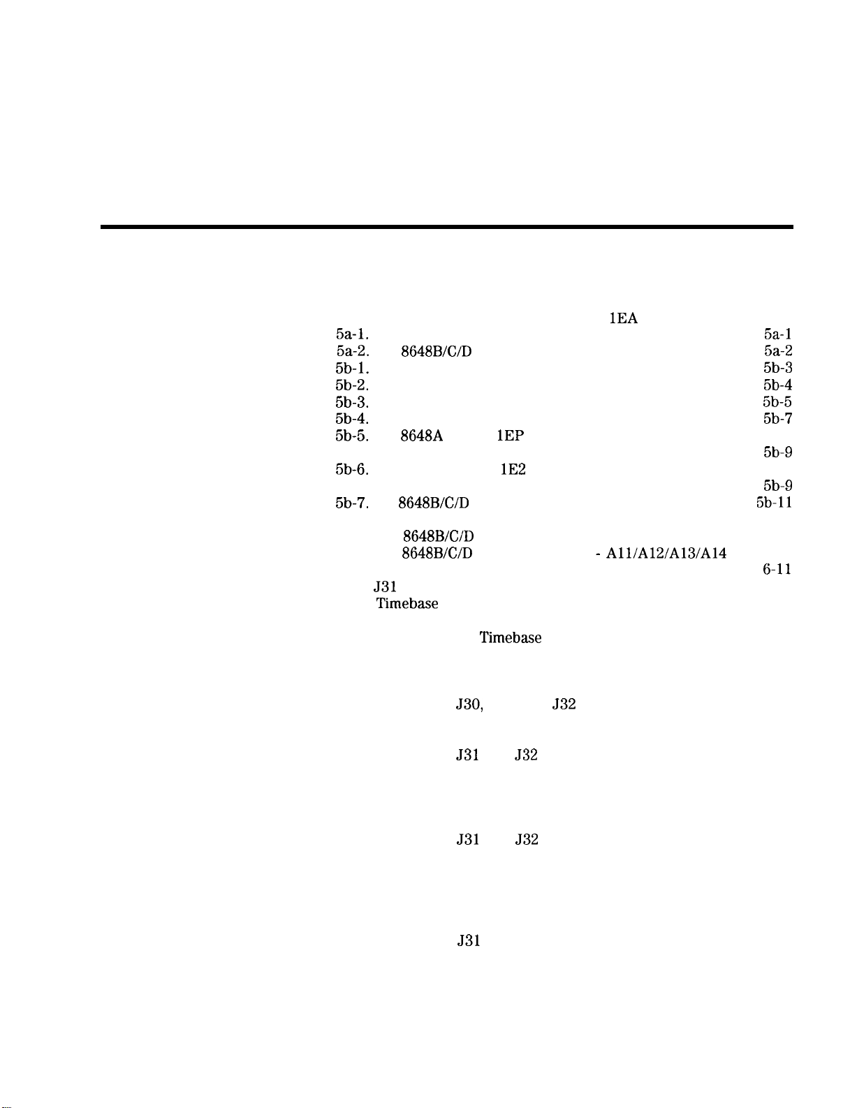
Figures
2-l. HP 8648 Status Register Model
2-2. Paging Encoding Status
3-l. Replacing the Fuse
...............
.................
3-2. Power Cable and Mains Plug
4-l. Typical Output Power with Option
HP 8648A Simplified Block Diagram
HP
Fuse Removal
Location Diagram
Simplified Block Diagram
...................
..................
...........
............
.......
.........
.......
Bottom View of Motherboard with Cover Removed . .
HP 8648A Block Diagram
HP
Option
..............
A30 Pager Encoder Block
Diagram ....................
HP 8648A Option
Al4 Modulation Generator Block
Diagram ....................
HP
Block Diagram (1 of 2)
6-l. HP 8648A Replaceable Parts
6-2. HP
6-3. HP
Replaceable Parts
Replaceable Parts
.............
...........
........
Detailed View ..................
7-l.
Test Point Extender
7-2. Timebase Adjust Switch Location
7-3. Internal Reference Oscillator Adjustment Setup
...............
..........
....
7-4. Pager Encoder Timebase Frequency Adjustment Setup
7-5. Variable Capacitor Location
7-6. AM Level and Distortion Test Setup 1
7-7. AM Level and Distortion Test Setup 2
7-8. Location of
531, and
7-9. AM Level Test Setup 1
7-10. AM Level Test Setup 2
7-11. Location of
and
7-12. Detector Offset Test Setup
7-13. Output Level Test Setup
7-14. AM Level: FE Test Setup 1
7-15. AM Level: FE Test Setup 2
7-16. Location of
and
7-17. Predistortion and Detector Offset Test Setup
7-18. Prelevel Test Setup
.................
.............
........
........
on the Motherboard
...............
...............
on the Motherboard
.....
..............
..............
.............
.............
on the Motherboard
.....
.....
7-19. Output Level: Frequency Extension Calibration Test
Setup ......................
7-20. AM Modulator Test Setup
7-21. Location of
on the Motherboard
7-22. Time Base DAC Test Setup
7-23. Motherboard Audio Path Test Setup
7-24. DCFM Test Setup
..................
7-25. Audio Generator Test Setup
..............
.........
.............
.........
.............
. .
2-13
2-18
3-3
3-4
4-3
6-3
6-9
7-3
7-4
7-4
7-6
7-7
7-9
7-9
7-10
7-11
7-11
7-12
7-13
7-14
7-15
7-15
7-16
7-17
7-18
7-19
7-20
7-21
7-22
7-24
7-25
7-26
Contents-9
Page 18
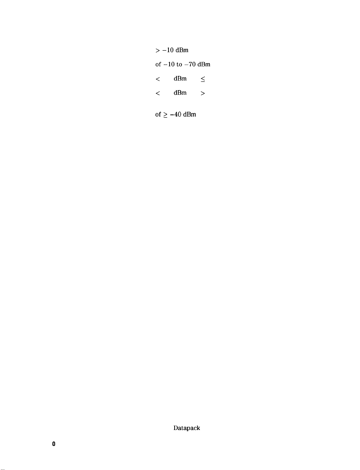
7-26. HF Power Level Accuracy Test Setup for Power Levels
...................
7-27. HF Power Level Accuracy Test Setup for Power Levels
...............
7-28. HF Power Level Accuracy Test Setup for Power Levels
7-29. HF Power Level Accuracy Test Setup for Power Levels
7-30. LF Output Level Test Setup .............
7-31. LF Power Level Accuracy Test Setup for Power Levels
.................
7-32. LF Power Level Accuracy Test Setup for Power Levels
of<-40dBm .................
7-33. FSK Deviation Test Setup ..............
7-34. Filter Path Test Setup ................
7-35. Welcome Screen ..................
7-36. Important Information Screen ............
7-37. Choose Destination Location Screen .........
7-38. Select Program Folder Screen ............
7-39. Start Copying Files Screen .............
7-40. Installation Status Gauge ..............
7-41. Setup Complete Screen ...............
7-42. Setup Complete Screen ...............
7-43. HP Service Support Program Group .........
7-44. HP Service Software for PC’s Selections .......
7-45. User Information Dialog Box ............
7-46. DUT Selection Dialog Box ..............
7-47. Select Test Equipment and Tests Window .......
7-48. Save As Dialog Box .................
7-49. HP Service Support Software Window ........
7-50. HP Service Support Software Window Displaying Test
Results .....................
7-51. Print the Log File? Dialog Box ...........
7-52. The User Information Window ............
7-53. Test Equipment Drivers in the File Drop-Down Menu .
7-54. Adding Test Equipment Using the Test Equipment Menu
7-55. Adding the Equipment Information Using the New Test
Equipment Window ...............
7-56. Removing and Editing Test Equipment Using the Test
Equipment Window ...............
7-57. The Select Test Equipment and Tests Window ....
7-58. Test Equipment Drivers in the File Drop-Down Menu .
7-59. Adding a Device Driver Using the Test Equipment
Drivers Window .................
7-60. Using the Open Dialog box to Search for a Device
Driver File to Add ................
7-61. Removing a Device Driver Using the Test Equipment
Drivers Window .................
7-62. Test Drivers in the File Drop-Down Menu ......
7-63. Adding a Test Driver Using the Test Drivers Window
7-64. Using the Open Dialog Box to Search for a Test Driver
File to Add ...................
7-65. Removing a Test Driver Using the Test Drivers Window
7-66. Datapacks in the File Drop-Down Menu .......
7-67. Adding a
Using the Datapacks Window . . .
7-27
7-28
7-28
7-29
7-30
7-31
7-32
7-33
7-34
7-36
7-37
7-38
7-38
7-39
7-39
7-40
7-40
7-42
7-42
7-43
7-43
7-44
7-46
7-47
7-47
7-49
7-50
7-51
7-52
7-53
7-54
7-56
7-57
7-57
7-58
7-59
7-60
7-61
.
7-61
7-62
7-63
7-64
Contents-l
Page 19
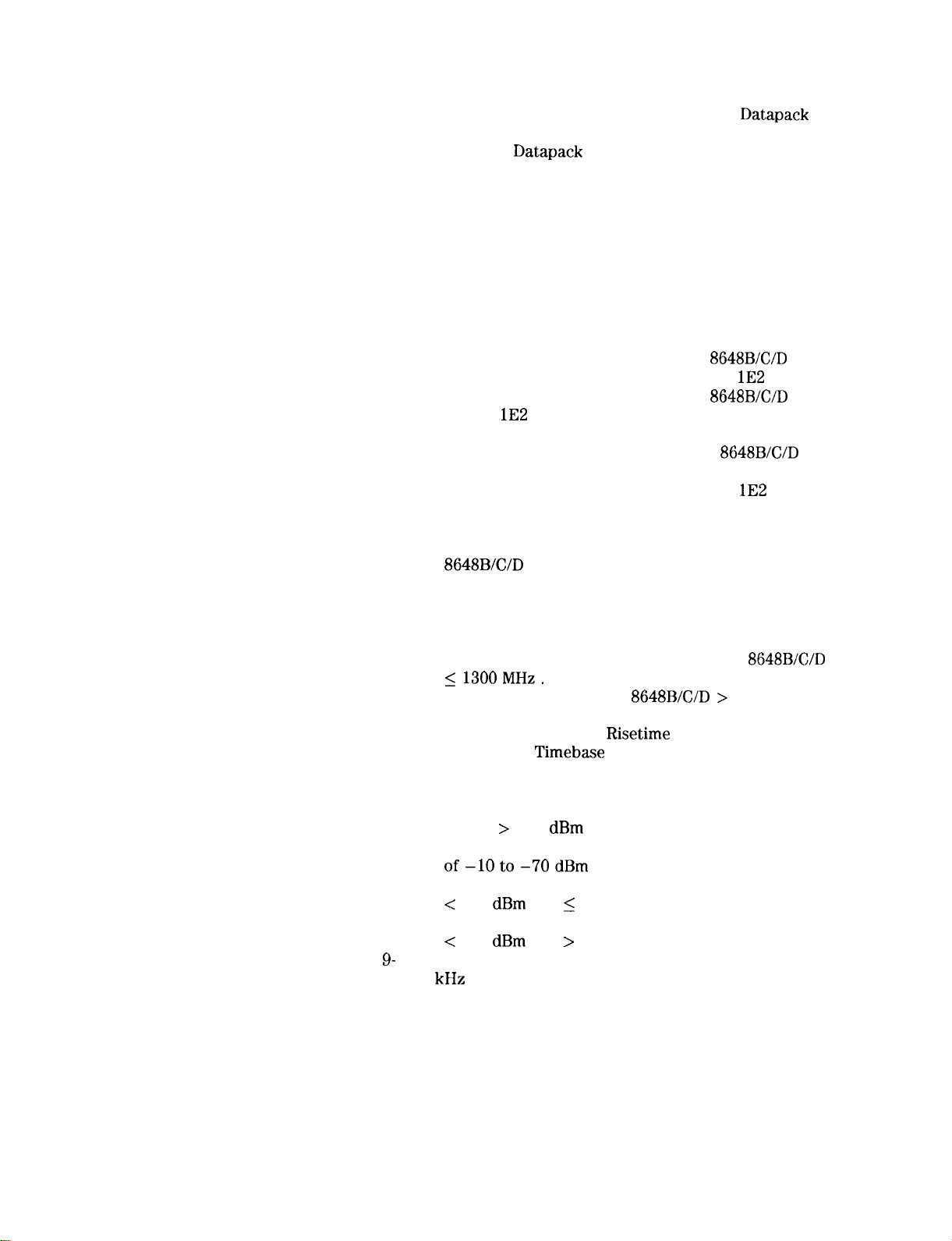
7-68. Using the Open Dialog Box to Search for a
File to Add
7-69. Removing a
7-70. 110 Port Error Message
7-71. HP Service Support Program Group
...................
Using the Datapacks Window
...............
.........
7-72. HP Service Software for PC’s Selections .......
7-73. Password Requested by User Information Dialog Box .
7-74. HP8648 Motherboard Repair Utility Window .....
7-75. HP Service Support Program Group
.........
7-76. HP Service Software for PC’s Selections .......
7-77. Password Requested by User Information Dialog Box .
7-78. HP8648 Motherboard Repair Utility Window .....
8-l. FM Accuracy Equipment Setup
8-2. FM Accuracy Equipment Setup for HP
8-3. FM Accuracy Equipment Setup for Option
...........
. .
....
8-4. FM Accuracy Equipment Setup for HP
Option
8-5. FM Distortion Equipment Setup
8-6. FM Distortion Equipment Setup for HP
8-7. AM Accuracy Equipment Setup
8-8. AM Accuracy Equipment Setup for Option
8-9. AM Distortion Equipment Setup
...................
...........
. .
...........
....
...........
8-10. Phase Modulation Distortion Equipment Setup ....
8-11. Phase Modulation Distortion Equipment Setup for HP
...................
8-12. Residual FM Equipment Setup
8-13. Harmonics Equipment Setup
8-14. Spurious Equipment Setup
............
............
.............
8-15. DC FM Frequency Error Equipment Setup ......
8-16. Equipment Setup for the HP 8648A and HP
8-17. Equipment Setup for the HP
..................
> 1300 MHz .
8-18. Pulse Modulation On/Off Ratio Equipment Setup. ...
8-19. Pulse Modulation On/Off
Equipment Setup.
.
8-20. Pager Encoder Timebase Accuracy Equipment Setup .
8-21. FSK Deviation Accuracy Equipment Setup ......
8-22. Internal Timebase: Aging Rate Test Setup ......
8-23. HF Power Level Accuracy Test Setup Setup for Power
Levels > -10 dBm
...............
8-24. HF Power Level Accuracy Test Setup for Power Levels
...............
8-25. HF Power Level Accuracy Test Setup for Power Levels
1300 MHz
...........
8-26. HF Power Level Accuracy Test Setup for Power Levels
...........
1. Frequency Accuracy Equipment Setup
........
9-2. 9 kHz RF Level Accuracy Equipment Setup .....
.
7-64
7-65
7-67
7-68
7-68
7-69
7-69
7-70
7-70
7-71
7-72
8-6
8-7
8-8
8-9
8-10
8-11
8-12
8-13
8-14
8-15
8-16
8-17
8-19
8-20
8-21
8-22
8-23
8-26
8-27
8-29
8-30
8-36
8-38
8-39
8-39
8-40
9-3
9-8
Contents-l 1
Page 20
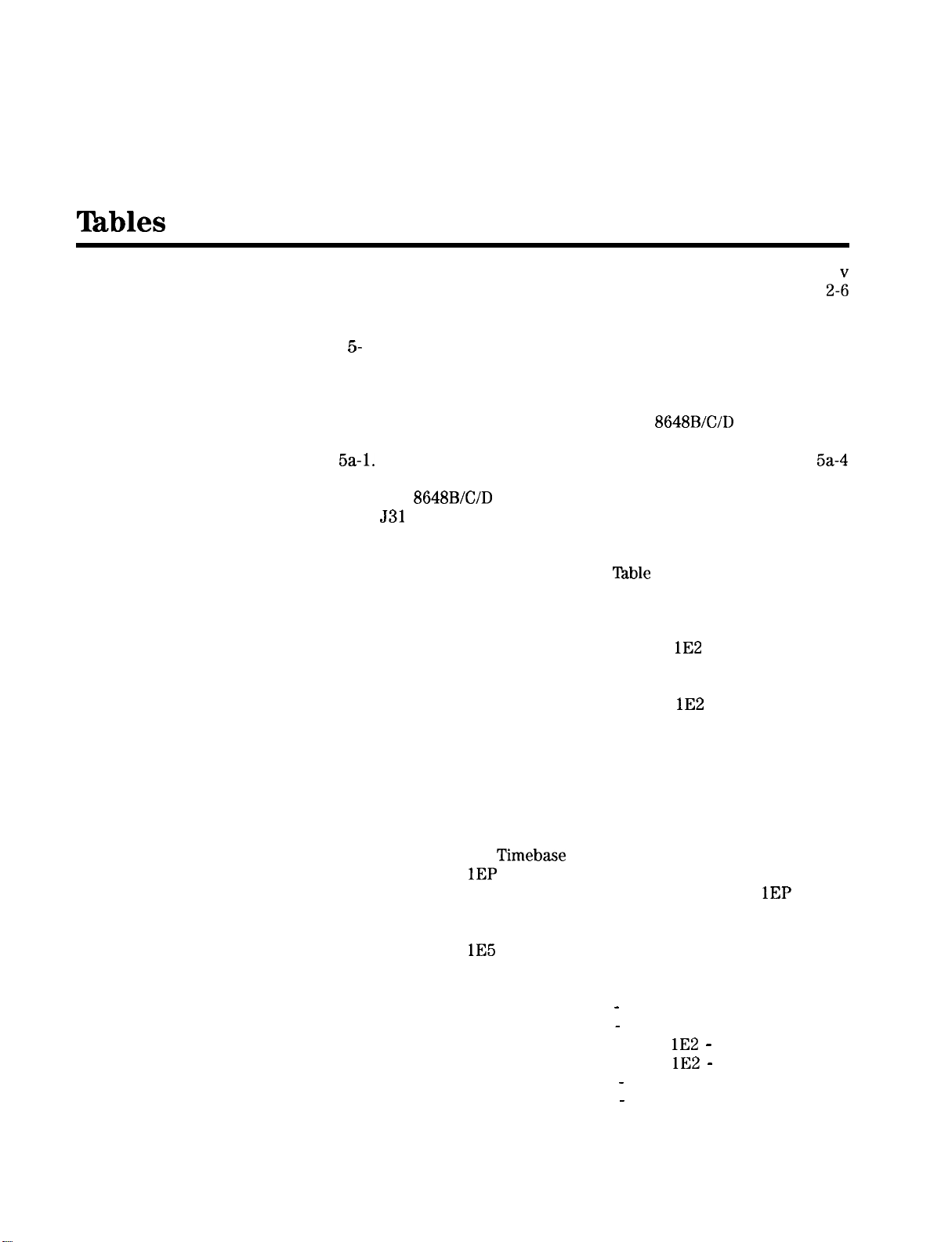
O-l. Hewlett-Packard Sales and Service Offices ......
2-1. Programming Command Statements and Descriptions .
2-2. Dictionary of Terms .................
2-3. IEEE 488.2 Capabilities ...............
1. Recommended Test Equipment ...........
5-2. Adjustments and Performance Tests Required after
Repair or Replacement of an HP 8648A Assembly .
5-3. Adjustments and Performance Tests Required after
Repair or Replacement of an HP
Assembly ....................
Al Front Panel (Keyboard) .............
6-l. HP 8648A Replaceable Parts .............
6-2. HP
7-l.
Test Point Extender Parts List ..........
Replaceable Parts ...........
7-2. An Example of Calibration Data for Power Sensors . .
8-l. High Power Level Accuracy Work Table .......
8-2. FSK Deviation Accuracy Work
.........
8-3. HP 8648A Test Record ...............
8-4. HP 8648A Test Record ...............
8-5. FM Accuracy Performance Test ...........
8-6. FM Accuracy Performance Test Option
......
8-7. FM Distortion Performance Test ...........
8-8. AM Accuracy Performance Test ...........
8-9. AM Accuracy Performance Test Option
.....
8-10. AM Distortion Performance Test ...........
8-l 1. Phase Modulation Distortion Performance Test ....
8-12. Residual FM Performance Test ............
8-13. Harmonics Performance Test .............
8-14. Spurious Performance Test .............
8-15. DC FM Frequency Error Performance Test ......
8-16. RF Level Accuracy Performance Test .........
8-17. Pager Encoder Timebase Accuracy Performance Test
(Option
Only) ................
8-18. FSK Deviation Accuracy Performance Test (Option
Only) ......................
8-19. Internal Timebase: Aging Rate Performance Test
(Option
Only) ................
8-20. HP 8648B Test Record ...............
8-21. HP 8648B Test Record ...............
8-22. FM Accuracy Performance Test
8-23. FM Accuracy Performance Test
8-24. FM Accuracy Performance Test Option
8-25. FM Accuracy Performance Test Option
8-26. FM Distortion Performance Test
8-27. FM Distortion Performance Test
Part 1 .......
Part 2 .......
Part 1 . .
Part 2 . .
Part 1 .......
Part 2 .......
8-28. AM Accuracy Performance Test ...........
2-20
2-43
5-2
5-5
5-6
6-5
6-13
7-2
7-53
8-25
8-33
8-41
8-42
8-43
8-44
8-45
8-46
8-48
8-50
8-51
8-51
8-52
8-53
8-54
8-55
8-60
8-60
8-60
8-61
8-62
8-63
8-63
8-64
8-64
8-65
8-65
8-66
Contents-l 2
Page 21
8-29. AM Accuracy Performance Test Option
8-30. AM Distortion Performance Test . . . . . . . . . . .
8-31. Phase Modulation Distortion Performance Test
8-32. Phase Modulation Distortion Performance Test
8-33. Residual FM Performance Test . . . . . . . . . . . .
8-34. Harmonics Performance Test . . . . . . . . . . . .
8-35. Spurious Performance Test . . . . . . . . . . . . .
8-36. DC FM Frequency Error Performance Test . . . . . .
8-37. RF Level Accuracy Performance Test
8-38. RF Level Accuracy Performance Test
8-39. RF Level Accuracy Performance Test
8-40. RF Level Accuracy Performance Test with Options
. . . . . . . . . . . . . . . .
8-41. RF Level Accuracy Performance Test
8-42. Pulse Modulation On/Off Ratio Performance Test
(Option
8-43. Pulse Modulation Rise Time Performance Test (Option
Only) . . . . . . . . . . . . . . . . . . . .
8-44. Internal Timebase: Aging Rate Performance Test
(Option
8-45. HP 8648C Test Record . . . . . . . . . . . . . . .
8-46. HP 8648C Test Record
8-47. FM Accuracy Performance
8-48. FM Accuracy Performance Test
8-49. FM Accuracy Performance Test Option
8-50. FM Accuracy Performance Test Option
8-51. FM Distortion Performance Test
8-52. FM Distortion Performance Test
8-53. AM Accuracy Performance Test . . . . . . . . . . .
8-54. AM Accuracy Performance Test Option lE2
8-55. AM Distortion Performance Test . . . . . . . . . . .
8-56. Phase Modulation Distortion Performance Test
8-57. Phase Modulation Distortion Performance Test
8-58. Residual FM Performance Test . . . . . . . . . . . .
8-59. Harmonics Performance Test . . . . . . . . . . . .
8-60. Spurious Performance Test . . . . . . . . . . . . .
8-61. DC FM Frequency Error Performance Test . . . . . .
8-62. RF Level Accuracy Performance Test
8-63. RF Level Accuracy Performance Test
8-64. RF Level Accuracy Performance Test
8-65. RF Level Accuracy Performance Test with Options
8-66. RF Level Accuracy Performance Test
8-67. Pulse Modulation On/Off Ratio Performance Test
(Option
8-68. Pulse Modulation Rise Time Performance Test
(Option
8-69. Internal Timebase: Aging Rate Performance Test
(Option lE5 Only) . . . . . . . . . . . . . . . .
8-70. HP 8648D Test Record . . . . . . . . . . . . . . .
8-71. HP 8648D Test Record . . . . . . . . . . . . . . .
8-72. FM Accuracy Performance Test
8-73. FM Accuracy Performance Test
8-74. FM Accuracy Performance Test Option
8-75. FM Accuracy Performance Test Option
Only) . . . . . . . . . . . . . . . .
Only) . . . . . . . . . . . . . . . .
Part 2
. . . . . . . . . . . . . . . .
Only) . . . . . . . . . . . . . . . .
Only) . . . . . . . . . . . . . . . .
Part 1
Part 2
Part 1 . . . . .
Part 2 . . . . .
Part 3 . . . . .
Part 4 . . . . .
‘1
Part 1 . . . . . . .
Part 2 . . . . . . .
Part 1 . . . . .
Part 2 . . . . .
Part 3 . . . . .
Part 4 . . . . .
. . . . .
Part 1
Part 2
. . . . . . .
Part 1 . .
Part 2 . .
. . . . .
Part 1
Part 2
. . . . . . .
. . . . . . .
Part 1 . .
Part 2 . .
8-68
8-70
8-71
8-71
8-71
8-72
8-73
8-74
8-75
8-81
8-81
8-82
8-82
8-82
8-83
8-83
8-85
8-86
8-87
8-87
8-88
8-88
8-89
8-89
8-90
8-92
8-94
8-95
8-95
8-95
8-96
8-97
8-98
8-99
8-105
8-106
8-106
8-107
8-107
8-108
8-108
8-109
8-110
8-111
8-111
8-112
8-112
Contents-13
Page 22
8-76. FM Distortion Performance Test
8-77. FM Distortion Performance Test
8-78. AM Accuracy Performance Test
Part 1
Part 2
...........
8-79. AM Accuracy Performance Test Option
8-80. AM Distortion Performance Test
...........
8-81. Phase Modulation Distortion Performance Test
8-82. Phase Modulation Distortion Performance Test
8-83. Residual FM Performance Test
8-84. Harmonics Performance Test
8-85. Spurious Performance Test
............
............
.............
8-86. DC FM Frequency Error Performance Test
8-87. RF Level Accuracy Performance Test
8-88. RF Level Accuracy Performance Test
8-89. RF Level Accuracy Performance Test
.......
.......
......
Part 1
Part 2
Part 3
.....
Part 1
Part 2
.....
.....
.....
8-90. RF Level Accuracy Performance Test with Options
................
8-91. RF Level Accuracy Performance Test
Part 4
.....
8-92. Pulse Modulation On/Off Ratio Performance Test
(Option
Only) ................
8-93. Pulse Modulation Rise Time Performance Test
(Option
Only) ................
8-94. Internal Timebase: Aging Rate Performance Test
(Option
Only) ................
1. HP 8648A Frequency Accuracy Supplemental
Verification Test .................
9-2. HP 8648B Frequency Accuracy Supplemental
Verification Test .................
9-3. HP 8648C Frequency Accuracy Supplemental
Verification Test .................
9-4. HP
Frequency Accuracy Supplemental
Verification Test .................
9-5. HP 8648A Option
Supplemental Verification Test
9-6. HP 8648B Option
Supplemental Verification Test
9-7. HP 8648C Option
Supplemental Verification Test
Frequency Accuracy
..........
Frequency Accuracy
..........
Frequency Accuracy
..........
9-8. HP 8648D Option lE5 Frequency Accuracy
Supplemental Verification Test
..........
9-9. HP 8648B 9 kHz RF Level Accuracy Supplemental
Verification Test .................
HP 8648C 9 kHz RF Level Accuracy Supplemental
Verification Test .................
9-l 1. HP 8648D 9 kHz RF Level Accuracy Supplemental
Verification Test .................
8-113
8-114
8-115
8-116
8-117
8-117
8-118
8-118
8-119
8-120
8-121
8-122
8-128
8-129
8-129
8-130
8-131
8-131
8-131
9-4
9-4
9-5
9-5
9-6
9-6
9-7
9-7
9-9
9-9
9-10
Contents-14
Page 23

Operation
“Operation” contains the following information:
1 Operation Provides a quick overview of the instrument’s
operation.
la Operation
Examples
lb Operation
Reference the instrument’s functions.
lc Operation
Messages HP-IB remote operation messages.
Provides examples to help you learn how to
operate the instrument.
Provides quick access to information about each of
Provides information about both front-panel and
Note
For information about service messages numbered 500 and above,
refer to Chapter
“Service Error Messages.”
Operation l-l
Page 24

Quick Overview
1. Power Key
2. Display
s
7
8648 Signal Generator
Press
to power up the instrument. The instrument powers up
to the same state it was in when power was turned off, except that
the RF output will be turned off and the digit-select arrow keys
and
will be reset to the least significant digit.
The display can be one of two displays depending on the serial
number prefix of your instrument as illustrated below.
,
AMPUI~E
1-2 Operation
Page 25
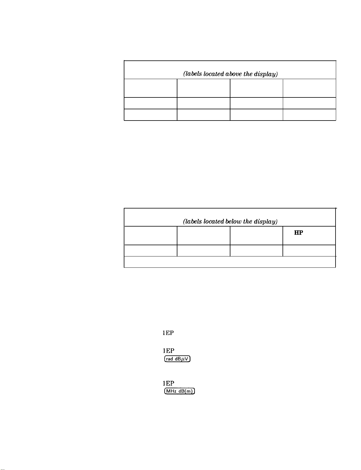
The following table describes the prefixes that apply to the various HP
8648 models equipped with an LCD.
A. Liquid Crystal Display (LCD)
display)
BP 8648A BP 8648B
Prefix Preflx
3636A and below 3623A and below 3623A and below 3613A and below
3643U and below 3642U and below 3642U and below 3642U and below
The display contrast of the LCD can be achieved using the adjustment
that is located on the rear panel of these instruments. Note that this
adjustment is only available for instruments equipped with an LCD.
It allows you to adjust the contrast of the LCD. Turn the adjustment
to optimize the display for viewing from most angles. If the display is
blank, first attempt to adjust the display contrast before returning the
instrument for service.
The following table describes the prefixes that apply to the various HP
8648 models equipped with a VFD.
B. Vacuum Fluorescent Display (VFD)
BP 8648A BP 8648B BP 8648C
Prefix Prefix Prefix Prefix
3836A and above 3836A and above 3836A and above 3836A and above
BP 8648C
Prefix
display)
BP 8648D
Prefix
8648D
3. Function and Data Keys
3836U and above 3836U and above 3836U and above 3836U and above
The VFD is a 2x40 display. The intensity of the this display is at 100
% and cannot be adjusted.
The keys in the FUNCTION and DATA blocks allow you to enter
values for setting the frequency, amplitude, and modulation level of
the RF output signal.
If Option
pager encoder (ENCODER) mode and FM mode.
If Option
mode, the
input alphabetical characters using the DATA and MODULATION
SOURCE blocks when you are in pager encoder mode.
If Option
mode, the
key must be used to store any numeric or alphabetic characters
entered by way of the DATA and MODULATION source blocks.
I
is present, the [FM) (ENCODER) key will toggle between
is present and the signal generator is in the ENCODER
key functions as a SHIFT key. This key lets you
is present and the signal generator is in the ENCODER
key functions as an ENTER key. The ENTER
I
I
Operation 1-3
Page 26
4. Increment Set Keys
When you press a FUNCTION key, that function becomes the active
function. Press
the active function. Press
function setting by the increment value. (If Option
and the signal generator is in the ENCODER mode, these keys have
alternate functions.)
to view or change the increment value for
or
at any time to change the active
is present
5. Knobs
6. MEMORY
If Option
mode, the
starts or stops any pager encoding activity. In addition, in this mode,
the
move the blinking cursor between each parameter when you are
entering the pager encoding settings.
The knobs are always active when the instrument is in local (front
panel) control. Turn them to increase or decrease the frequency or
amplitude of the RF output. Press
adjust the knob’s resolution.
Press
reference value and turn on the reference mode. Press (REF ON/OFF) to
turn on and off the reference mode without changing the reference
value. When the reference mode is on, the displayed value indicates
the offset between the reference value and the RF output signal.
If Option 1EP is present and the signal generator is in the ENCODER
mode, the AMPLITUDE/ENCODER knob is used to enter a setting for
a pager encoding parameter.
Memory registers allow you to save instrument set-ups and recall
them whenever you wish. Press
number to save the instrument’s current settings.
settings, press
allow you to recall registers in numerical sequence. You can arrange
your registers in up to ten different sequences.
and
is present and the signal generator is in the ENCODER
key functions as a START/STOP key. This key
function as PREV and NEXT keys. These keys let you
or
next to each knob, to set the displayed value as the
and enter a two-digit register
and enter the register number. The arrow keys
next to each knob, to
recall the
1-4 Operation
The number of the currently selected sequence and the last register
selected are always displayed in the lower-left corner of the display to
help you keep track of where you are in your testing process.
(If Option
on any pager encoding menu.) The memory register examples
provided in Chapter la, “Operation Examples,” show you how
to create a sequence and how to delete or add registers in your
sequence.
is present, the sequence and register are not displayed
Page 27
7. Modulation Source
Press
ON/OFF) to turn on or off the modulation source. Press
or
to select one of the internal source tones
for modulating the RF output signal. These tones are also available
as an output signal at the MOD INPUT/OUTPUT port when they are
selected. Press
or
to ac- or dc-couple an external
audio source via the MOD INPUT/OUTPUT port.
Press
+ EXT
to frequency modulate the RF signal with
the internal 1 kHz tone and an external source at the same time.
(Additional internal plus external modulation capabilities are available
for HP-IB operation.)
+ EXT
will also amplitude or phase
modulate the RF signal with the internal 1 kHz tone but it will not be
dc-coupled.
If Option 1EP is present, the
Option
is present, the
(FREQUENCY) key, or if
(FREQUENCY/WAVEFORM)
key scrolls between five states: a fixed 1 kHz internal source and a
variable-frequency internal source with four different waveform
selections. The four modulation waveforms are sine, triangle, square,
and sawtooth (or ramp).
Operation
Page 28

Operation Examples
This section contains operating examples to help you learn how to
operate the signal generator. These examples can be performed
without any additional equipment. The pager testing example can
only be performed if Option 1EP is present.
Getting Started
If this is the first time you have operated this instrument, perform
each of the following examples for a quick introduction to general
operation. After you have completed the examples, try operating the
instrument’s remaining functions on your own. If you have trouble
or want additional information on a function, refer to Chapter lb,
“Operation Reference.” If a message is displayed that you do not
understand, refer to Chapter lc, “Operation Messages.”
Operation Examples la-l
Page 29
Operation Examples
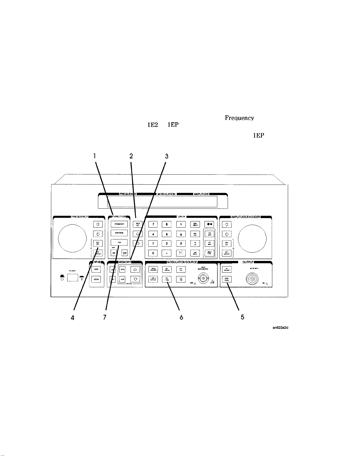
This section provides the following examples of signal generator
operation. The item numbers of the operation examples correspond to
the numbers called out on drawing of the instrument front panel.
1. Setting the RF Output Signal
2. Incrementing or Decrementing the RF Output Signal
3. Using the Memory Registers
4. Offsetting the RF Output from a Reference
5. Holding the Output Attenuator Range
6. Setting a User Selectable Modulated
(Option
or
Only)
7. Signaling a Numeric-Type FLEX Pager (Option
RF
A
and Waveform
Only)
la-2 Operation Examples
Page 30
Setting the RF Output Signal
In this example, you will set the frequency, amplitude, and modulation
level of the RF output signal.
Setting the Frequency
Setting the Amplitude
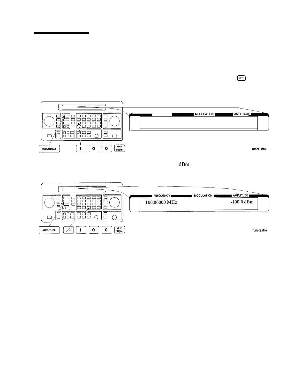
1. Set the frequency to 100 MHz using the keys shown below the
instrument diagram.
If you make a mistake while entering a value, press
to correct
it.
FREQUENCY
100.00000 MHz
2. Set the amplitude to -100 dBm.
Operation Examples la-3
Page 31

Turn on the RF Output
3. Press
to turn on the RF output.
RF OFF is displayed below the amplitude setting when the RF
output is turned off.
Setting the
Modulation
4. Set the FM deviation to 3 kHz.
The modulation rate is displayed below the deviation setting. Use
the MODULATION SOURCE keys to select a modulation source and
turn modulation on or off.
FREQUENCY
100.00000 MHz
MODULATION
FM 3.00
AMPLITUDE
-100.0 dBm
,
la-4 Operation Examples
Page 32

Incrementing or Decrementing the RF Output Signal
In this example, you will increment the amplitude and frequency of
the RF output signal.
Preliminary Steps
Using the Knob
1. If they are not already set, set the frequency to 100 MHz, and the
amplitude to -100 dBm.
FREQUENCY
100.00000 MHz
2. Increment the amplitude using the knob.
Press
or
when you wish to adjust the increment resolution.
MODULATION
AMPLITUDE
-100.0
.dnv
Operation Examples la-5
Page 33

Using the Increment
keys
3. Enter a frequency increment of 25 kHz.
The $ symbol is displayed when you press
that the displayed value is the increment set value.
-101.0
4. Increment the RF output frequency in 25 kHz steps.
The increment keys affect the last FUNCTION selected
(FREQUENCY, AMPLITUDE, FM, AM or
to indicate
000
0
0 00
q c
0 q OCI
FREQUENCY
100.02500 MHz
MODULATION
-101 .O dBm
la-6 Operation Examples
Page 34

Using the Memory Registers
The memory register examples show you how to create a sequence of
registers, delete a register from that sequence, renumber the registers
in the sequence, and insert a new register in the sequence.
Up to 10 register sequences can be defined (0 through 9). A sequence
can contain up to 100 registers (00 through 99). There are a total of
300 registers available in the instrument. The registers can be used
in the sequences in any combination (such as 10 sequences of 30
registers each, or 3 sequences of 100 registers each) as long as the
total does not exceed 300 registers. It is not possible to have all 10
sequences each contain 100 registers as that would be 1000 registers.
(If Option
is present, there are a total of 70 registers available.)
SEQ 0
SEQ
9
\
FM
REG 00
99
36.0dBm
RFOFF
Operation Examples la-7
Page 35

Saving Instrument
Settings in Register
Sequences
In this ten step example, you will use the memory keys to create
a sequence containing three registers. Each register will contain a
different frequency setting.
Selecting the Sequence
1. Select sequence 0.
If there are registers saved in sequence 0, the message shown
in the display below will not appear. Note that the steps in this
example will cause the settings in registers 00, 01, and 02 of
sequence 0 to be changed.
.dnv
Saving Settings in Registers
2. Set the frequency to 10 MHz.
3. Save the instrument settings in register 00.
FREQUENCY
10.00000 MHz
SEQ 0 REG 00
MODUIATION
,
la-8 Operation Examples
Page 36

4. Set the frequency setting to 11 MHz.
MODULATION
5. Save the instrument settings in register 01.
6. Set the frequency to 12 MHz.
Operation Examples la-9
Page 37

7. Save the instrument settings in register 02.
FREQUENCY
12.00000 MHz
SEQ 0 REG 02
Checking the Sequence
8. Recall the registers in sequence 0.
The
which key was pressed last
and
FREQUENCY
SEQ 0 REG 01
keys recall registers or sequences depending on
12.00000 MHz
SEQ 0 REG 02
10.00000 MHz
SEQ 0 REG 00
MODULATION
or
MODULATION
AMPLITUDE
AMPLITUDE
la-l 0
Operation Examples
Checking a
9. Select sequence 1.
SEQ
Sequence
FREQUENCY
MODULATION
Page 38

10. Step through the registers in sequence 1 if there are registers
saved in it.
Note
Sequence 1 does not contain the settings you saved in sequence
0. The instrument enables you to save different settings in each
sequence to create up to ten different sequences for your testing.
Remember when you save or recall a register, be sure that the correct
sequence is also selected.
Operation Examples
la-l 1
Page 39

Deleting a Register
from the Sequence
In this example, you will delete a register from the sequence you
created in the preceding example.
Selecting the Sequence
1. Select sequence 0.
Note
FREQUENCY
SEQ 0
MODULATION
AMPLITUDE
Deleting a Register
2. Delete register 01 from sequence 0.
The contents of the register are recalled when it is deleted. This
allows you to resave the contents if you need to.
FREQUENCY
11 .OOOOO MHz
SEQ 0 REG --
MODULATION
AMPLITUDE
,
la-12 Operation Examples
delregl
Page 40

Step through the remaining registers in sequence 0.
3.
The deleted register number has been removed from the sequence.
Note that the instrument does not renumber the registers when
one is deleted.
12.00000 MHz
SEQ 0 REG 02
10.00000 MHz
0 REG 00
MODULATION
AMPUTUDE
Operation Examples la-13
Page 41

Renumbering the
Registers in a
Sequence
In this example, you will eliminate the skip from register 00 to register
02 in sequence 0 caused when you deleted register 01 in the previous
example.
Decreasing the Register Number
1. Delete register 02.
The settings saved in register 02 are recalled when it is deleted.
2. Save the settings from register 02 into register 01.
12.00000 MHz
SEQ 0 REG 01
la-14 Operation Examples
Page 42

Checking the Sequence
3. Step through the register sequence.
Note
In this example, you renumbered one register. When you need to
renumber two or more registers, use
each register until you get to the last register in the sequence, then
use (DEL).
12.00000
MHz
instead of (DEL) to recall
I
Operation Examples la-15
Page 43

Inserting a Register in
a Sequence
In this example, you will insert a register into the sequence you
created in the previous example. The process involves incrementing
each register number that comes after the point in the sequence
where you wish to insert a register.
1. Recall the last register in sequence 0.
FREQUENCY
12.00000 MHz
SEQ 0 REG 01
MODULATION
AMPUTUDE
2. Save the recalled settings into register 02.
Operation Examples
la-l 6
3. Recall register 00.
Register 01 can now be used to save the settings that are saved in
register 00.
FREQUENCY
MODULATION
,
Page 44

4. Save the recalled settings into register 01.
Register 00 can now be used to save the new settings.
FREQUENCY
10.00000 MHz
SEQ 0 REG 01
Saving a New Register
5. Set the frequency to 8 MHz.
FREQUENCY
8.00000 MHz
I
6. Save the settings in register 00.
MODULATION
MODULATION
AMPUTUDE
,
I
Press
to check the new sequence.
8.00000 MHz
Operation Examples
la-l 7
Page 45

Offsetting the RF Output from a Reference
In this example, you will enter an RF output frequency, set it as the
reference value, and then offset the RF output frequency 10 MHz
below the reference value.
Setting the
Reference
Value
1. Set the frequency to 500 MHz.
500.00000 MHz
2. Set 500 MHz as the reference frequency.
The A symbol appears in the display to indicate that the reference
mode is selected. The output frequency is still 500 MHz.
la-l 6
Operation Examples
Page 46

Offsetting the RF
output
3. Offset the output frequency 10 MHz below the reference
frequency.
You can enter in the offset value directly, or use the knob or
and
keys.
FREQUENCY
-10.00000
MODULATION
AMPLITUDE
Attention!
In the reference mode, the output frequency equals the reference
frequency
Turning
4. Turn off the reference mode to display the actual output
frequency.
5. Turn on the reference mode without changing the reference
frequency.
the displayed offset frequency.
the Reference Mode Off or On
FREQUENCY
490.00000
MHz
MODULATION
AMPLITUDE
-------
.
I
Operation Examples la-19
Page 47

6. Change the displayed units to
Note that for amplitude, reference settings are displayed in
units only.
FREQUENCY
MODULATION
Setting a New Reference Value
7. Set the current output frequency as the new reference frequency
at any time.
la-20 Operation Examples
Page 48

Holding the Output Attenuator Range
In this example, you will hold the output attenuator so it does not
change ranges when you change the amplitude setting. This will
prevent attenuator range changes from affecting the output signal.
Set the Amplitude
Level
Holding the
Attenuator
1. Set the amplitude level to -82 dBm.
2. Hold the attenuator at this setting.
MODULATION
-82.0
AMPLITUDE
-82.0
HOLD
Operation Examples la-21
Page 49

Adjusting the
Amplitude
3. Adjust the amplitude setting.
Now amplitude changes do not cause the attenuator to change its
range setting. Consequently, amplitude changes are limited to the
range provided by the instrument’s vernier. For information about
the instrument’s vernier ranges, refer to Chapter lb, “Operation
Reference.
la-22 Operation Examples
Page 50

Setting a User
Selectable
Modulated
Frequency and
Waveform
(Option lE2 or
Note
Setting the
Modulation Level
This modulation example can only be performed if Option
is present.
In this example, you will select the modulation level and the
modulated frequency and waveform of the RF signal output.
1. Select FM modulation with a deviation of 25 kHz.
Either LAM) or
The modulation type (FM, AM, or
(deviation or depth) is displayed on the top line of the front-panel
display as shown.
modulation may be used instead of (FM.
and the modulation level
or
Operation Examples la-23
Page 51

Setting the Modulated
Waveform
(Frequency/
Waveform)
2. Press the
(FREQUENCY/WAVEFORM) key until
selected.
Repetitively pressing the
(FREQUENCY/WAVEFORM) key
selects one of five states:
n A fixed 1 kHz sine-wave internal source.
n A variable-frequency sine-wave source
(indicated by SIN preceded by the frequency value).
n A variable-frequency triangle source (TRI).
n A variable-frequency square-wave source
n A variable-frequency sawtooth (or ramp) source (SAW).
is
Setting the Modulated
Frequency
3. Set the modulated frequency to 1.5 kHz.
The
key is the only accepted units key.
la-24 Operation Examples
Page 52

Signaling a
Numeric-Type
FLEX Pager
(Option
Only)
In this example, you will set up the pager encoder to send a signal
appropriate to test a numeric-type FLEX pager.
Note
This pager encoding example can only be performed if Option
present.
The front panel of the Option 1EP instrument is different from the
standard instrument’s front panel. The green and blue labels are
incorporated for the pager encoding mode only. Therefore, these keys
have multiple functions on instruments with Option
FORMAT FLEX
POLARITY NORMAL
FILTER ON
is
HP 8648A Option
Signal Generator
Operation Examples la-25
Page 53

Setting Up Pager
Encoding
The following steps are required to set up pager encoding on the
signal generator. Details of setting each parameter are provided
following this overview.
1. Before entering the signal generator pager encoder mode,
set the correct carrier frequency and FM deviation for the
pager-under-test. (The FM deviation is 4.8 kHz for FLEX and is
4.5
for POCSAG.)
2. Press
below the amplitude setting when the RF output is turned off.)
3. Enter the pager encoder mode by pressing
wasn’t the last active function, press (FM) (ENCODER) twice.
4. Set up the pager encoder parameters to meet the test requirements
of your specific pager.
Use the
encoder parameters. The cursor will blink around the first letter
of the active parameter. The
sequentially through each pager encoder parameter and the
(PREV) ke
To move between settings for each parameter, rotate the
AMPLITUDE/ENCODER knob until the desired setting is
displayed. When characters are entered by way of the keypad
(such as the capcode), terminate the entry with the
(ENTER) key.
5. Start signaling the pager after all of the encoder parameters are set
by pressing the
to turn on the RF output. (RF OFF is displayed
(ENCODER). If FM
(NEXT) and
y moves backward sequentially.
(PREV) keys to scroll through the
(NEXT) key moves forward
(START/STOP) key.
la-26 Operation Examples
Page 54

Entering Pager
Encoding Settings
1. Display the first pager encoder menu.
After setting your pager’s carrier frequency and an FM deviation
of 4.8 kHz (for a FLEX pager) on the signal generator, press the
(ENCODER) key once again to display the first pager encoder
menu (FORMAT). The
(ENCODER) key toggles between the
frequency modulation menu and the pager encoder menu.
Selecting the Format
Settings
FORMAT
POLARITY
MODmION
FLEX
NORMAL
FILTER ON
2. Set FORMAT to FLEX, POLARITY to NORMAL, and FILTER to ON.
a. With the blinking cursor on the “F” of FORMAT, set the FLEX
format by rotating the AMPLITUDE/ENCODER knob until FLEX
is displayed.
b. Press the
(NEXT) key to move the blinking cursor to
POLARITY, then use the AMPLITUDE/ENCODER knob to set
the polarity to NORMAL.
c. Using the
(NEXT) key and the AMPLITUDE/ENCODER
knob, set FILTER to ON.
FORMAT
POLARITY
FLEX
NORMAL
FILTER ON
Press the
(NEXT) key to move to the next page.
Operation Examples la-27
Page 55

Selecting the Data
Rate and Pager Type
Settings
3. Set DATA RATE to
AMPLITUDE/ENCODER knob and the
and PAGER TYPE to NUMERIC, using the
(NEXT) key.
You may choose to set the data rate to one of the other settings;
your FLEX pager should automatically adjust.
1
Press the
DATA RATE
PAGER TYPE NUMERIC
(NEXT) key to move to the next page.
4. Set VECTOR TYPE to STANDARD using the AMPLITUDE/ENCODER
knob.
STANDARD
la-28 Operation Examples
Press the
(NEXT) key to move to the next page.
Page 56

Selecting the Message
Settings
5. You may choose one of the five fixed messages (only numbers one
and five are useful for numeric pagers) or you may define your
own message. For this example, use your own phone number as
the user-defined message:
a. Set MESSAGE NO. to 6 and MESSAGE LENGTH to 40 using the
AMPLITUDE/ENCODER knob and the
(NEXT) key.
Selecting
Transmission
Repetitions and
amplitude
b. Press the
(NEXT) key again to select the FREE MESSAGE
parameter.
c. Enter your phone number with the numeric keys and
terminate your entry with the
MESSAGELENGTH 40
Press the
MESSAGE NO.6
(NEXT) key to move to the next page.
6. Set MODE to SINGLE and AMPLITUDE to 0.
AMPLITUDE/ENCODER knob and the
(ENTER) key.
using the
(NEXT) key. Enter
the numeric values using the numeric keys and the
(ENTER) key.
Press the NEXT
key to move to the next page.
Operation Examples la-29
Page 57

7. Set IMMEDIATE STOP to OFF, HEADER to ON, and TERMINATOR to
ON using AMPLITUDE/ENCODER knob and the
These are default settings that normally would not be adjusted.
(NEXT) key.
Selecting the Pager
(Address)
Note
IMMEDIATE STOP OFF
HEADER ON
Press the
8. Enter your pager’s
menu. The
alphabetical characters. For example, to enter the following
Th
AMPLITUDE/ENCODER knob, set DUMMY CALL to OFF.
The pager’s
parameters of the last two menus.
(NEXT) key to move to the next page.
A0012477, press
(ENTER).
contains information that automatically sets the
(address) in the pager code
(SHIFT) key is required to enter
(SHIFT),
en, using the
TERMINATOR ON
(A), @i?ZV),
(NEXT) key and the
la-30 Operation Examples
Press the
(NEXT) key to move to the next page.
Page 58

9. ADDRESS TYPE and ADDRESS1 are set automatically when the
is entered in the previous menu. If A0012477 was
entered, SHORT and 0045245 would be displayed respectively.
Generally, you would not change these settings.
Selecting the Protocol
Settings
Note
Press the
10. FRAME, PHASE, and COLLAPSE CYCLE are also set automatically
when you enter the pager’s
previously, 0 11, D, and 4 would be displayed.
If MODE is set to BURST or CONT instead of SINGLE, you may choose
to change the collapse cycle to 0 to 7. With a collapse cycle of 4,
the pager will receive the message once every 16 frames
collapse is 0 or 1, the pager will receive the message either every
frame (2’), or every other frame (2l).
Press the
(NEXT) key to move to the next page.
If you entered A0012477
If the
(NEXT) key to move to the next page.
Operation Examples
la-3 1
Page 59

Selecting the Roaming
Mode Settings
11. Set ROAMING MODE to NONE using the AMPLITUDE/ENCODER
knob.
Encoding
Press the @j (NEXT) key to move to the next menu.
12. To start encoding after selecting all pager encoder parameters,
press the
(START/STOP) key.
la-32 Operation Examples
Page 60

Operation Reference
This chapter describes each of the instrument’s functions including all
of the front panel keys, the rear panel connectors, and the optional
remote interface and memory interface. This information is presented
in the same functional groups as the front panel key functional
groupings.
Note
Option
Consequently the front panel of the Option
different from the standard instrument’s front panel. The green and
blue labels are incorporated for the pager encoding settings only.
Therefore these keys have multiple functions on instruments with
Option
adds a pager encoder capability to the standard functions.
instrument is
Operation Reference
1 b-l
Page 61

Frequency/Amplitude
Frequency and Amplitude
1. Knob
2. Digit-Select Arrow Keys
Note
The knob and reference set keys work similarly for both frequency
and amplitude settings.
Turn the knobs to increment or decrement the frequency and
amplitude settings. The knobs are always active when the instrument
is in local operation.
If Option 1EP is present and the signal generator is in the ENCODER
mode, the knob in the AMPLITUDE/ENCODER block is used to select
the desired setting for each pager encoder parameter.
Press these digit-select arrow keys
changed with the knob.
The knobs increment the selected digit only. For information about
incrementing by an arbitrary value using the increment set keys, see
“Increment Set” in this chapter.
to select the digit to be
Operation Reference
1 b-2
Page 62

Frequency/Amplitude
3. REF SET
4. REF ON/OFF
Output Power
Trouble?
Press
RF output setting as the reference value. The reference value
is stored in non-volatile memory until you replace it by pressing
When you press
value and the units. When
the offset between the reference value and the RF output signal.
The RF output signal is not changed when you press this key.
to turn on the reference mode and to set the current
again.
the
symbol is displayed between the
appears, the displayed value indicates
Units
When you press
or kHz. For amplitude, values can be entered in any of the amplitude
units provided, but they are displayed in dB only.
Press (REF ON/OFF] to turn off the reference mode if it is on, or to turn
on the reference mode without changing the reference value.
When you turn on the reference mode, the displayed value indicates
the offset between the reference value and the current RF output
setting.
The RF output signal is not changed when you press this key.
If the RF output power seems too low, look for
between the power level value and the
that reference mode is turned on. The displayed value is not the
output power level; it is the offset between the reference value and
the output power. To exit the reference mode, press
can then reset the output power to the desired level.
for frequency, values can be entered in MHz
in the display
indicator. The
tells you
ON/OFF].
Operation Reference
1 b-3
Page 63

Function
Function
1. FREQUENCY
The RF output frequency range for each model is shown in the
following table. When making frequency changes, the instrument does
not turn off the RF output. However, the power does blank for a few
milliseconds when crossing the frequencies at 249, 501, 1001, 1260,
1600, 2001, 2520, and 3200 MHz.
Frequency Ranges
HP 8648A
HP 8648B
HP 8648C
HP
9 kHzto2000 MHz
9
9
1000 MHz
3200 MHz
4000 MHz
Frequency switching typically takes less than 75 ms at frequencies
lower than 1001 MHz, and less than 100 ms at higher frequencies.
1 b-4
Operation Reference
Page 64

Function
2. AMPLITUDE
3. FM
AM
The RF output amplitude range is shown in the following table. When
making amplitude changes, the instrument does not turn off the RF
output. The period of any over- or under-ranging that may occur
during level transitions is typically less than 30 ms.
Output Amplitude Ranges
Press
HP 8648A
HP 8648BICID
HP
with Option
to set the peak deviation for frequency modulation. Then
to 1000 MHz
MHz
MHz
< 100
1000 MHz
1500 MHz
2100 MHz
MHz
MHz
to
136
+13to
+
+17to136
+20to
+19to136
+17to136
+15to136
+13to136
136
to
136
136
use the data entry keys to enter the desired value of deviation. The
values allowed depend on the RF frequency selected. See Chapter 4,
“Specifications” for peak deviation specifications.
Press (AM) to set the amplitude modulation range. Then use the data
entry keys to set the desired value of range. Values from 0 through
100% are allowed.
Press
to set the peak deviation for phase modulation. Then use
the data entry keys to enter the desired value of deviation. The
values allowed depend on the RF frequency selected. See Chapter 4,
“Specifications” for peak deviation specifications.
Operation Reference
1 b-5
Page 65

Function
Setting Up the
Pager Encoder
Note
The pager encoder mode is available only on instruments with
Option
Option
functions. Consequently the front panel of the Option
is different from the standard instrument’s front panel. The green
and blue labels are incorporated for the pager encoding settings only.
Therefore these keys have multiple functions on instruments with
Option
FORMAT FLEX
POLARITY NORMAL FILTER ON
adds pager encoding/signaling capabilities to the standard
instrument
Operation Reference
1 b-6
HP 8648A Option
For numeric messages, the following keys are assigned for the special
characters in addition to the standard numeric keys (0 to 9).
Signal Generator
Front
Panel Key
S
S
UU UU
Space
Space SpaceSpace
Character B3 B2
(Hyphen)(Hyphen)
SpareSpare
BO
1 0 1 01 0 1 0
1 0 1 11 0 1 1
1 1 0 01 1 0 0
1 1 0 11 1 0 1
11101110
11111111
Page 66

1'
1. ENCODER
Function
Note
Before selecting the pager encoder mode check that the correct pager
carrier frequency and FM deviation have been set.
To select the pager encoder mode, press
(ENCODER) twice:
once to set FM deviation, then again to toggle between the standard
functions and the pager encoder mode. The display will look like the
following:
FORMAT
POLARITY
FLEX
NORMAL FILTER ON
This format menu is always displayed first when the pager encoder
mode is selected.
The
(PREV) and
(NEXT) keys are used to move the blinking
cursor between each parameter.
The knob in the AMPLITUDE/ENCODER block is used to select the
desired setting for each pager encoder parameter.
To start or stop encoding, press
(START/STOP).
Operation Reference
1 b-7
Page 67

Function
Setting the Format
Note
The format menu, shown in the previous figure, has the following
settings:
n FORMAT selects the pager protocol being tested.
FLEX:
FLEX-TD:
POCSAG:
PN15:
RESYNC:
FLEX format
FLEX-TD format
POCSAG format
Pseudorandom Sequence (PN 15)
Re-synchronization function (for FLEX/FLEX-TD
pagers only)
SERVICE:
Servicing the HP 8648A Option
Depending on the format selected, the parameter menus will be
different. Messages displayed while sending encoding signals are also
unique to each selection.
n POLARITY selects the data polarity.
NORMAL:
“1”: Carrier
“0”: Carrier + Deviation
Normal polarity
Deviation
“1”: Carrier
Carrier
Deviation “10”: Carrier
“11”: Carrier + (Deviation/J)
“01”: Carrier
Deviation “00”: Carrier
Deviation
Deviation
INVERSE:
“1”: Carrier + Deviation “1”: Carrier
“0”: Carrier
n FILTER selects whether or not the baseband modulation filter
Inverse polarity
Deviation “10”: Carrier
Deviation
Carrier + Deviation
Bessel low-pass filter, -3
Deviation
“11”: Carrier
“01”: Carrier + (Deviation/S)
at 3.9
(Deviation/J)
is used.
Normally the filter is on.
ON:
OFF:
Uses the low-pass filter
Does not use the low-pass filter
lb-6 Operation Reference
Page 68

FLEX/FLEX-TD
Function
Setting the Data Rate and Pager Type
The parameter menu for the data rate and the pager type looks like
the following:
MODULATION
DATA RATE
PAGER TYPE NUMERIC
n DATA RATE specifies how fast the data stream is output in bits per
second and whether it is 2-level or 4-level FSK.
1600 bps, 2-level FSK
3200 bps, 2-level FSK
3200 bps, 4-level FSK
6400 bps, 4-level FSK
n PAGER TYPE specifies the type of message a pager under test can
respond to and is selectable from the following:
TONE ONLY:
NUMERIC:
ALPHANUMERIC:
HEX/BIN:
Short Message/Tone only type
Numeric type
Alphanumeric type
HEX/Binary type
Operation Reference lb-9
Page 69

Function
q If NUMERIC is selected, the next setting to be selected is VECTOR
TYPE as shown:
TYPE
n VECTOR TYPE identifies the type of message as follows:
STANDARD:
The pager-under-test displays the numeric
STANDARD
message it receives.
SPECIAL:
The pager-under-test converts the numeric
message to a pre-defined message which is
displayed.
NUMBERED:
The message numbers are assigned for each
paging address separately starting at 0
and progressing up to a maximum of 63 in
consecutive order.
If NUMBERED is selected, the next parameter to be selected is
NUMBER as follows:
lb-10 Operation Reference
encode21
NUMBER is for setting the initial number of the numbered
numeric message that will be transmitted. The allowable range
is 0 to 63.
Page 70

q
If HEX/BIN
LENGTH:
is selected, the next setting to be selected is
BLOCKING
Function
Note
BLOCKING LENGTH
I
n
BLOCKING LENGTH
indicates the bits per character as follows:
1 bit per character
7BITS:
8BITS:
14BITS:
7 bits per character
8 bits per character
14 bits per character
16 bits per character
Enter the message in the hexadecimal format to the MESSAGE
NO. 6 in the message menu.
When
7 BITS
or
14 BITS
are selected, the total number of
hexadecimal character of the message must be a multiple of 7
characters (28 bits).
I
Operation Reference
1
Page 71

Function
Setting the Message
The message menu looks like the following:
MESSAGE NO.1
MESSAGE LENGTH 40
MESSAGE NO. is defined as the following where “X” represents the
phase setting:
0:
Arbitrary message set from the external controller using the
HP-IB capability. The data must be entered in units of words.
Refer to
the Buffer Memory for the Arbitrary Messages” in Chapter
START
FRAME and STOP FRAME are defined in the following
:PAGing
. . . ,
and “Using
2.
menu:
START FRAME
STOP FRAME 127
lb-12 Operation Reference
The frames between the START FRAME and STOP FRAME will be
transmitted. The allowable ranges for both are 000 to 127.
1: Displays: 0123456 [Xl
where “X” =
“3” for phase D.
2: Displays: ABCDEFG
3: Displays: TEST PAGING :XXXXXXX
where “XXXXXXX” = “PHASE A”, “PHASE B”, “PHASE C”, or
“PHASE D”.
4: Displays: ALPHANUMERIC 40CHARS TEST PAGING :XXXXXXX
where “XXXXXXX” = “PHASE A”, “PHASE B”, “PHASE C”, or
“PHASE
5: Displays: 8888888888888888888888888888888888888888
for phase A, “1” for phase B, “2” for phase C,
.
Page 72

Function
for LCD test with 40 characters of “8”.
6:
User-definable message, up to 40 characters long, set from
the front panel. Enter numeric messages with the keypad.
Alphanumeric messages require the
(SHIFT) key
to access the alphabetical characters (blue letters) above
the keypad. If required alphabetical characters are not
available on the front panel, send a message from an external
controller over HP-IB. Refer to
:
n MESSAGE LENGTH specifies the maximum number of characters that
FLEX
:
string”’ in Chapter 2.
:
will be sent out and displayed in the message field. The allowable
range is 1 to 40. After specifying the number of characters, press
(ENTER) to save the new value.
When the value of this parameter is equal to or greater than the
length of the message, the whole message will be sent out.
When the value of this parameter is less than the length of the
message, only the characters specified by this parameter are output.
(For example, if the MESSAGE NO. is 1 (0123456[Xj) and the MESSAGE
LENGTH is 5, the message which is displayed and will be sent out is
actually 01234.)
Operation Reference lb-13
Page 73

Function
Setting the Encoding Mode
The number of times a message is transmitted and the level of that
transmission are determined by the following menu:
MODE BURST
BURSTS 003
MODE determines whether the message will be output once or
multiple times when
SINGLE:
BURST:
CONT:
AMPLITUDE sets the output signal level of the carrier.
BURSTS sets the number of times the message will be transmitted.
This parameter is displayed only when the MODE parameter is set to
BURST. The allowable range is 1 to 256.
Outputs the message once.
Outputs the message the number of times specified
in the BURSTS field (3 times in this example).
Outputs the message continuously until the
(START/STOP) key is pressed a second
time. (Note: The collapse cycle described later
on in this section will determine how often the
message will be transmitted per cycle.)
(START/STOP) is pressed.
lb-14 Operation Reference
RF OFF is displayed below the amplitude setting when the RF output
is turned off. To toggle the RF signal output on and off, press
HOLD is displayed when the step attenuator is held at its current
range setting. To toggle the attenuator hold function on and off,
press
Page 74

Function
Another menu is displayed as follows for completing the Encoding
Mode:
IMMEDIATE STOP OFF
HEADER ON
TERMINATOR ON
IMMEDIATE STOP terminates pager signaling as follows when a stop
event occurs.
Note
ON:
OFF:
Terminates pager signaling immediately.
Default setting. Terminates pager signaling just
before the next instance the pager is on.
(If TERMINATOR is set to ON, the pager encoder
generates the re-synchronization pattern in the
frame that was supposed to contain the message.)
HEADER sets whether the idle frame signal is output in the frame
before the first message.
ON:
OFF:
Default setting. Outputs the idle frame signal.
Does not output the idle frame signal.
TERMINATOR sets whether the re-synchronization pattern is output
after the last message. The collapse cycle will determine in which
frame the re-synchronization pattern appears after the
(START/STOP) key is pressed to stop or at the end of a burst
sequence (refer to “FLEX/FLEX-TD Signaling Examples”).
ON:
Default setting. Outputs the re-synchronization
pattern.
OFF:
Does not output the re-synchronization pattern.
If TERMINATOR is set to OFF, the pager under test is not asynchronized.
Therefore, the pager can not be synchronized with the future
page until the re-synchronization pattern is sent. To send the
re-synchronization pattern, set TERMINATOR to ON in this menu or
select RESYNC in the format menu.
Operation Reference lb-15
Page 75

Function
Note
Entering the Pager
(Address)
The pager code menu looks like the following:
n PAGER CODE accepts alphanumeric characters up to 16 digits.
Use the numeric keys to enter the
alphabetical character, press
To select an
(SHIFT) before the numeric
key associated with the desired alphabetic character. Terminate
your entry with the
A FLEX/FLEX-TD pager’s
information. Entering the
(ENTER) key.
contains address and protocol
in the PAGER CODE data field
automatically sets up the ADDRESS TYPE, ADDRESSI, and ADDRESS2 in
the address menu, and the FRAME, PHASE, and COLLAPSE CYCLE in the
protocol menu as well.
The following table shows an example of the conversion from
to the parameters. Note that the values of COLLAPSE CYCLE
and FRAME are changed.
A0012477
n DUMMY CALL inserts a message with all 5s in all non-call phases. This
SHORT
SHORT
SHORT
0045245
0045245
0045245
None
None
None
011
011
127
COLLAPSE
D
D
D
4
2
2
is required by the FLEX-TD standard (RCR STD-43A) for sensitivity
testing.
ON:
Default setting. Activates the dummy call function
for equalizing the FSK deviation. An address for
the non-call phases must be set.
OFF:
Does not activates the dummy call function. Idle
frames are set in the non-call phases.
lb-16 Operation Reference
Page 76

The address menu will display the following information:
n ADDRESS TYPE selects the address length.
Function
encode41 .Cdr
SHORT:
LONG:
Short address
Long address
ADDRESS1 is the 7-digit short address or the primary address of the
long address.
n ADDRESS2 is the 7-digit secondary address of the long address. (This
is displayed only when ADDRESS TYPE is set to LONG.)
If DUMMY CALL is ON, the following address menu is displayed.
ADDRESS TYPE
ADDRESS1 0032769
SHORT
ADDRESS TYPE (DUMMY CALL) displays the address type used in the
non-call phases (automatically set).
SHORT:
LONG:
Short address
Long address
Note
n ADDRESS1 is the 7-digit short address or the primary address of the
long address.
n ADDRESS2 is the 7-digit secondary address of the long address. (This
is displayed only when ADDRESS TYPE (DUMMY CALL) is LONG.)
To equalize the FSK deviation, the addresses for DUMMY CALL should
contain an equal number of “1” and “0”.
Operation Reference lb-17
Page 77

Function
Setting the Protocol
The protocol menu displays the following information when
is the previously entered
I
I-
CYCLE 00
CYCLE 0
000
PHASE A
REPEAT 0
These parameters, except for CYCLE, are all automatically set when
the
n CYCLE: Defines the start cycle. The allowable range is 0 to 14.
is entered in the PAGER CODE data field:
FRAME: Defines the start frame where the message is located. The
allowable range is 0 to 127.
n PHASE: Defines the phase for the pager. The allowable range is A, B,
C, or D.
COLLAPSE CYCLE: Determines how many times a message repeats
within a cycle when BURST or CONT is active in the encoding MODE
setting. The default setting of 4 will repeat the message once every
16 frames
n REPEAT: Displayed only if FLEX-TD is selected in the format menu.
The allowable range is 0 through 7.
Defines the repetition transmission value. Determines how many
cycles the message will be repeated. The allowable range is 0 to 3.
1 b-l
Page 78

Setting the Roaming Mode
Function
ROAMING MODE NONE
n ROAMING MODE determines the mode in which a pager is tested.
NONE:
SSID:
Tests a pager without the roaming mode.
Tests a pager in the SSID mode which responds to
a simulcast transmission system. SSID consists of
three words as follows:
q
SSIDl (BIWOOO):
Local Channel ID
Coverage Zone
•I
Country Code
Traffic Management Flag
q Frame Offset (BIWlOl)
SSID, NID:
Tests a pager in the SSID and NID modes. The NID
mode, in addition to the SSID mode, is a roaming
network for covering wider multiple areas. NID
consists of a network address and a short message
vector as follows:
•I SSIDl (BIWOOO):
Local (Channel) ID
Coverage Zone
q
SSID2
Country Code
SSID Traffic Management Flag (TMF)
q Frame Offset (BIWlOl)
q
NID
Network Address: 21 bits
Short Message Vector:
RF Channel (M)
Multiplier
(Service) Area
NID Traffic Management Flag (TMF)
Operation Reference
1 b-l 9
Page 79

Function
Note
When ALPHANUMERIC is selected in the PAGER TYPE field and
SSID, NID is selected in the ROAMING MODE field, the maximum
allowable range of the MESSAGE LENGTH field is limited to 35.
The following menu is displayed for setting the SSID mode for a pager
to be tested:
n LOCAL ID: Defines the local channel ID of a pager under test. The
allowable range is 0 to 511.
n COVERAGE ZONE: Defines the coverage zone of a pager under test.
The allowable range is 0 to 3 1.
n COUNTRY CODE: Defines the country code. The allowable range is
0 to 1023.
n SSID TMF: Defines the SSID traffic management flag. This value is
automatically set when the
(address) is entered in the
PAGER CODE data field. The allowable range is 0 to 15.
After completing the previous menu, set FRAME OFFSET in the
following menu:
n FRAME OFFSET: Defines the number of frames to be offset by
range is 0 to 63.
lb-20 Operation Reference
Page 80

Function
The next menu is displayed for setting the NID mode after completing
the SSID mode settings only if the SSID and NID modes are selected:
n ADDRESS: Defines the network address which appears on the RF
channel within the address field in predicted frames. The allowable
range is 2058240 to 2062335.
RF CH: Represents each RF channel obtained by the formula as
follows:
RF CH = Modulo 8 of Integer [(RF Freq. kHz)/(channel space
The allowable range is 0 to 7.
n AREA: Defines the service area identification. The allowable range is
0 to 31.
n MULTIPLIER: Defines how much the network address is extended.
The allowable range is 0 to 7.
n NID TMF: Defines NID traffic management flag. This value is
automatically set when the
(address) is entered in the
PAGER CODE data field. The allowable range is 0 to 15.
Operation Reference lb-21
Page 81

Function
Message During Encoding
To start and stop encoding after selecting all pager encoder
parameters, press the
display is shown during encoding a pager under test:
(START/STOP) key. The following
Note
Note
REPEAT is displayed additionally only if FLEX-TD is selected in the
format menu.
If MESSAGE NO. is set to 0, the display is changed as follows:
If the RF output is turned off, AMPLITUDE x .
for RF OFF. While encoding, the blinking cursor is on the first
character A of AMPLITUDE or R of RF OFF.
will be substituted
1 b-22
Operation Reference
Page 82

Function
Signaling Examples
The following examples illustrate the frame structure for the three
transmission repetition settings. The HEADER and TERMINATOR
parameters are set to ON (default), and the COLLAPSE CYCLE (CC) is
set to 1 and 2 (messages will be repeated every 2 frames (2l) and
4 frames
n SINGLE Mode Example
q Since HEADER is set to ON, the idle signal is output at Frame 126.
q With TERMINATOR set to ON, the asynchronous state signal is
output after the message.
respectively).
Start Cycle: 10
Start Frame:
Collapse Cycle: Has no effect
CC= 1 idle message asynchronous
127
n BURST Mode Example
Start Cycle: 10
Start Frame:
Collapse Cycle: 1 (2l) and 2
Burst:
q Since HEADER is set to ON, the idle signal is output at Frame 126.
q With TERMINATOR set to ON, the asynchronous state signal is
3
output in the frame where the next message was supposed to
occur (as determined by the collapse cycle).
11
Cycle 10
Frame 126
CC= 1 idle message idle message idle message idle
CC=2 idle message idle idle idle message idle
10
127 0
11
11
11
1
2
11
3
4
127
11
5
asyn-
chronous
idle
11 11
6 7
idle message
11
11
asyn-
chronous
Operation Reference
1 b-23
Page 83

Function
n CONT Mode Example
Start Cycle: 10
Start Frame:
127
Collapse Cycle: 1 (2l) and 2
stop: Selected in frame f+ 1
Since HEADER is set to ON, the idle signal is output at Frame 126.
With TERMINATOR set to ON and IMMEDIATE STOP set to
OFF, selecting stop will replace the next message with the
asynchronous signal.
Cycle 10 10 11 11 11
0
1
2
message idle message idle
idle
CC=2 idle message
I I
idle
idle
idle . .
message idle
c
f+l
f
asyn-
chronous
idle idle asyn-
chronous
1 b-24
Operation Reference
Page 84

Function
Roaming Example
When the roaming function with SSID and NID is set to on with the
following conditions, the contents in each phase are shown in the
following table:
n 6400 bps, 4-level FSK
n Call in Phase: A
n Address Type: Long Address
n Roaming Mode: SSID, NID
(for Network Address)
IB
Idle
1 BIW 101 System Messages: Time Instruction,
Seconds Adjust: 0,
Daylight Savings: No (Standard Time),
Local Time Zone: Greenwich Meridian
2 Vector Type: Short Message/Tone Only,
Message Type: 3 Numeric Characters (000) with Short Address
Idle Idle
where,
BI:
AF:
VF:
MF:
IB:
Block Information
Address Field
Vector Field
Message Field
Idle Block
Operation Reference
1 b-25
Page 85

Function
If the firmware revision of the HP 8648A Option
is B.04.08 or
below, the contents in each phase are shown in the following table:
n 6400 bps, 4-level FSK
n Call in Phase: A
n Address Type: Long Address
Roaming Mode: SSID, NID
Dummy Address 2
block 2
where,
BI:
AF:
VF:
MF:
IB:
IB
Idle
Block Information
Address Field
Vector Field
Message Field
Idle Block
Dummy Message
Dummy Message
Idle
Dummy Message
Dummy Message
Idle
1 b-26
Operation Reference
Page 86

POCSAG
Function
Setting the Data Rate and Pager Type
The parameter menu for the data rate and the pager type looks like
the following:
n
DATA RATE
512:
1200:
2400:
n
PAGER TYPE
NUMERIC:
TONE ONLY:
ALPHANUM 7BIT:
ALPHANUM 8BIT:
ALPHANUMERIC:
DATA RATE
PAGER TYPE
5 12
512 bps
1200 bps
2400 bps
Numeric type
Tone only type
7-bit coded alphanumeric type entered by
hex-binary code
hex-binary code
7-bit coded alphanumeric type
FUNCTION 00
Operation Reference lb-27
Page 87

Function
Note
The ALPHANUM 7BIT and ALPHANUM 8BIT types can be used for
displaying two-byte special characters, for example Chinese
characters, through a conversion table.
The following examples show how the actual bit streams are
transmitted if
q
For ALPHANUM 8BIT
is set to the message (MESSAGE NO. 6):
First Byte Second Byte
MSB
LSB MSB
Bit number
Bit streams
Characters
q
For ALPHANUM
1011000010100001
B 0
A
1
The eighth bit (b8) is ignored as follows:
First Byte
MSB
LSB MSB
Second Byte
LSB
LSB
Bit number
b7 b6 b5 b4 b3 b2 bl
b7 b6 b5 b4 b3 b2 bl
Bit streams 01100000100001
Characters
(3)
0
1
When converting the binary data stream to 2-level FSK, the first bit
out becomes the least significant bit (LSB) of the 2-level symbol
with the following bit the most significant bit (MSB) of the symbol.
n FUNCTION determines the pager’s response depending on the pager
type. The allowable range is 00 to 11.
1 b-28
Operation Reference
Page 88

Setting the Message
The message menu looks like the following:
Function
MESSAGE NO.1
n MESSAGE NO. is defined as the following where “X” represents the
MESSAGE LENGTH 40
phase setting:
0:
Arbitrary message set from the external controller using the
HP-IB capability. The data must be entered in units of words.
Refer to
:
<NRl>,
:
:
. . . ,
FLEX
and “Using
the Buffer Memory for the Arbitrary Messages” in Chapter 2.
This arbitrary message buffer is divided into multiple segments
by assigning START BATCH and STOP BATCH in the following
menu:
FREQUENCY
AMlJlUDE
I
The allowable ranges for both are 000 to 127.
Displays: 0123456
1:
2: Displays: ABCDEFG [PI
3: Displays: TEST PAGING: POCSAG
4: Displays: ALPHANUMERIC 40CHARS TEST PAGING : POCSAG
5: Displays: 8888888888888888888888888888888888888888
for LCD test with 40 characters of “8”.
6:
User-definable message, up to 40 characters long, set from
the front panel. Enter numeric messages with the keypad.
Alphanumeric messages require the
(SHIFT) key
to access the alphabetical characters (blue letters) above
the keypad. If required alphabetical characters are not
available on the front panel, send a message from an external
Operation Reference
1 b-29
I
Page 89

Function
controller over HP-IB. Refer to
:
n MESSAGE LENGTH specifies the maximum number of characters that
I FLEX
: DEFine ‘string”’ in Chapter 2.
:
:
will be sent out and displayed in the message field. The allowable
range is 1 to 40. After specifying the number of characters, press
(ENTER) to save the new value.
When the value of this parameter is equal to or greater than the
length of the message, the whole message will be sent out.
When the value of this parameter is less than the length of the
message, only the characters specified by this parameter are output.
(For example, if the MESSAGE NO. is 1(0123456[-1) and the MESSAGE
LENGTH is 5, the message which is displayed and will be sent out is
actually 01234.)
lb-30 Operation Reference
Page 90

Setting the Encoding Mode
Function
The number of times a message
transmission are determined by
I
I 1
I
FREQUENCY
MODE BURST
BURSTS003
is transmitted and the level of that
the following menu:
MODE determines whether the message will be output once or
multiple times when
SINGLE:
BURST:
Outputs the message once.
Outputs the message the number of times specified
(START/STOP) is pressed.
in the BURSTS field (3 times in this example).
CONT:
Outputs the message continuously until the
(START/STOP) key is pressed a second
AMPLITUDE sets the signal output level of the carrier.
BURSTS sets the number of times the message will be transmitted.
This parameter is displayed only when the MODE parameter is set to
BURST. The allowable range is 1 to 255.
RF OFF is displayed below the amplitude setting when the RF output
is turned off. To toggle the RF signal output on and off, press
HOLD is displayed when the step attenuator is held at its current
range setting. To toggle the attenuator hold function on and off,
press
Operation Reference lb-31
Page 91

Function
Entering the Pager
(Address)
The pager code menu looks like the following:
PAGER CODE
n PAGER CODE accepts only numeric characters up to 7 digits.
Use the numeric keys to enter the
with the
(ENTER) key.
0000000
Terminate your entry
Message During Encoding
To start and stop encoding after selecting all pager encoder
parameters, press the
display is shown during encoding a pager under test.
(START/STOP) key. The following
Note
MESSAGE NO. 6
If the RF output is turned off, AMPLITUDE x .
AMPLITUDE O.OdBm
will be substituted
for RF OFF. While encoding, the blinking cursor is on the first
character A of AMPLITUDE or R of RF OFF.
1 b-32
Operation Reference
Page 92

RESYNC
Function
Setting the Encoding Mode
The following parameters must be set to activate the
resynchronization function for a FLEX/FLEX-TD pager under test:
BURSTS 001 AMPLITUDE
n BURSTS defines the number of data to make a pager
I
with this pager encoding signal. One burst is 1.92 s. The allowable
range is 000 to 256. 0 represents the continuous mode.
Note
This setting is required only when RESYNC is selected in the format
menu. The
(PREV) and
(NEXT) keys toggle the format menu
and this BURSTS menu. No other menus are displayed.
Message During
To start and stop encoding after selecting all pager encoder
parameters, press the
RESYNC SENDING
I
I
(START/STOP) key.
I
Note
If the RF output is turned off, AMPLITUDE x .
will be substituted
for RF OFF. While encoding, the blinking cursor is on the first
character A of AMPLITUDE or R of RF OFF.
Operation Reference
1 b-33
Page 93

Function
PN15
Setting the Data Rate
If PNl5 modulation is selected in the format menu, the following
parameters must be set to complete the pager encoder setup process.
DATA RATE
512 bps, 2-level FSK
1200 bps, 2-level FSK
1600 bps, 2-level FSK
2400 bps, 2-level FSK
3200 bps, 2-level FSK
3200 bps, 4-level FSK
6400 bps, 4-level FSK
Note
Note
This setting is required only when PNl5 is selected in the format
menu. The
(PREV) and
(NEXT) keys toggle the format menu
and this PN15 FSK data rate menu. No other menus are displayed.
Message During Encoding
To start and stop encoding, press the
PN15 SENDING
If the RF output is turned off, AMPLITUDE x .
for RF OFF. While encoding, the blinking cursor is on the first
character A of AMPLITUDE or R of RF OFF.
(START/STOP) key.
AMPLITUDE
encode31
will be substituted
1 b-34
Operation Reference
Page 94

Function
SERVICE
This function is used for servicing the HP 8648A Option lEP, and
provides a continuous FSK signal.
Setting the Data Rate
The following parameter must be set to activate the service function:
n CALIBRATION FSK is one of the data rates as follows:
512 bps, 2-level FSK
1200 bps, 2-level FSK
1600 bps, 2-level FSK
2400 bps, 2-level FSK
3200 bps, 2-level FSK
3200 bps, 4-level FSK
6400 bps, 4-level FSK
Note
Note
This setting is required only when SERVICE is selected in the format
menu. The
(PREV) and
(NEXT) keys toggle the blinking cursor
between the format parameter and this CALIBRATION FSK parameter.
No other menus are displayed.
Message During Servicing
To start and stop encoding, press the
If the RF output is turned off, AMPLITUDE x.
for RF OFF. While encoding, the blinking cursor is on the first
character A of AMPLITUDE or R of RF OFF.
(START/STOP) key.
will be substituted
Operation Reference
1 b-35
Page 95

Pulse Modulation
Pulse Modulation
Note
1. PULSE
Pulse modulation is valid only for instruments with Option
To select pulse modulation, press (AM) (PULSE) twice. If RF is on, the
display will look like the following representation. The
ON/OFF]
key enables or disables the pulse modulator.
Note
When the instrument is in the pulse modulation mode, pulse
modulation should be turned off using
ON/OFF) before switching
off the instrument. If the instrument is switched off while the pulse
modulation mode is turned on, the instrument will power up with no
RF output.
PULSE MOD
PULSE MOD
OF’F
The word PULSE is shown in the AMPLITUDE portion of the display
when pulse modulation is enabled ([MOD ON/OFF]) and the RF is
turned on
In this case, no RF will be present at the RF
output unless a TTL-high signal is applied to the rear-panel PULSE IN
connector.
1 b-36
Operation Reference
Page 96

Pulse Modulation
The following keys are invalid when the pulse modulation screen is
visible:
n
n
n @EC--
D
n
Operation Reference lb-37
Page 97

Increment Set
Increment Set
1. INCR SET
Note
Note
Press
to view or change the increment set value for the
currently active function (the active function is the last function key
you press;
press
0 is displayed between the value and the units. The
indicates that the displayed value is the increment set value.
An increment value cannot be set for the knobs or the memory recall
arrow keys.
Set Ranges
Function
Range
1 Hz to 999.75 MHz
FM Deviation
AM Denth
> 0.0 to 149.0
> 0.0 to 150.5
> 0.0 to 100 kHz
> 0.0 to 100%
(HP 8648A)
(HP
0.01 to 1.0 kHz
It is possible to set an increment value of greater resolution than can
be displayed or than the hardware can respond to. However, the
instrument records each arrow key press and will respond after the
appropriate number of presses.
1 b-38
Operation Reference
START/STOP Encoding
If Option
mode, the
is present and the signal generator is in the ENCODER
key functions as a START/STOP key to start or
stop the pager encoding when in the pager encoder mode.
PREV and NEXT
If Option
mode, the
is present and the signal generator is in the ENCODER
and
keys function as the PREV and NEXT keys to
change the blinking first character between each parameter when in
the pager encoder mode.
Page 98

Data
Data
\
1. MHz/dBm
Note
Press a units key after you enter a value. This terminates the entry.
Note that the units keys in the left column are each labeled with an
amplitude unit on the bottom and a frequency or modulation unit on
the top. The instrument applies the appropriate unit for the function
value you are entering. The bottom key in the row for instance,
terminates a
Memory register selections, sequence selections, and HP-IB address
entries do not require a units key to terminate the entry. These
entries are automatically terminated after the last digit is entered.
entry in radians or an amplitude entry in
Units Conversion
You can change the units of the displayed frequency or amplitude
value by selecting the FUNCTION (frequency or amplitude) and then
pressing a units key. The instrument will convert the displayed value
to the equivalent value for the units key you pressed.
ENTER
If Option 1EP is present and the signal generator is in the ENCODER
mode, the
key must be used to store any numeric or alphabetic characters
entered by way of the DATA and MODULATION source blocks.
key functions as an ENTER key. The ENTER
If Option 1EP is present and the signal generator is in the ENCODER
mode, the
input alphabetical characters using the DATA and MODULATION
SOURCE blocks when in the pager encoder mode.
key functions as a SHIFT key. This key lets you
Operation Reference lb-39
Page 99

2. Backspace
Press
the last digit entered.
when entering a numeric value to backspace and remove
3. emf
4.
Press these keys to display the amplitude value indicated on the key
label in electromotive force units. Emf is the RF output voltage with
no load. It is twice the output voltage with a 50 ohm load.
Press this key at any time while you are entering an amplitude or
reference offset value to change the sign of the value.
1 b-40
Operation Reference
Page 100

Instrument Preset
Instrument Preset
(POWER)
Note
Turn the instrument on while pressing the backspace key
perform an instrument preset. The instrument will power up to
factory-defined settings shown in the following table. Save and recall
registers are not affected by this operation.
Turn the instrument on while pressing the memory
perform a clear memory. This function erases all save/recall registers,
sets the HP-IB address to 19, and performs an instrument preset
where the instrument powers up to factory-defined settings shown in
the following table.
This will cause an error message to appear on the display:
627 Battery RAM failure
: memory lost.
This is normal.
to
key to
Operation Reference lb-41
 Loading...