


Keysight 87204/87206A, B, C Multiport Coaxial Switches
dc to 4 GHz, dc to 20 GHz, dc to 26.5 GHz
Technical Overview
High performance multiport switches for microwave and RF instrumentation and systems
––SP4T and SP6T configuration
––Exceptional repeatability for more than 5 million cycles
––Excellent isolation, typically >90 dB at 26.5 GHz
––Magnetic latching
––Terminated ports
––Self-interrupting drive circuit
––Fully compatible with Keysight 87130A/70611A switch drivers
Modern automated test systems demand higher accuracy and performance than ever before. The Keysight Technologies Inc. 87204A/B/C and 87206A/B/C multiport switches offer excellent insertion loss repeatability and high isolation necessary to achieve superior test system performance. Long life, repeatability, and reliability reduce the cost of ownership by reducing calibration cycles and increasing test system uptime. These features are vital to ATS measurement system integrity over time.
Description
The 87204A/B/C SP4T and 87206A/B/C SP6T terminated multiport switches provide the life and reliability required for automated test and measurement, signal monitoring, and routing applications. Innovative design and careful process control create switches which meet the requirements for highly repeatable switching elements in test instruments and switching interfaces. The switches are designed to operate for more than 10 million cycles. The exceptional 0.03 dB insertion loss
repeatability is warranted for 5 million cycles at 25 °C. This reduces sources of random errors in the measurement path and improves measurement uncertainty. Switch life is a critical consideration in production test systems, satellite and antenna monitoring systems, and test instrumentation. The longevity of these switches increases system uptime, and lowers the cost of ownership
by reducing calibration cycles and switch maintenance.
|
|
|
87204A,B,C |
|
|
|
|
50 Ω Termination |
|
|
|
|
|
|
|
6 |
5 |
3 |
2 |
C |
|
|
RF Port |
87206A,B,C |
|
|
|
|
|
|
|
|
|
|
6 |
5 |
4 |
3 |
2 |
1 |
C |
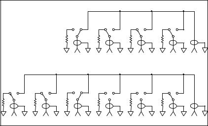
Figure 1. Keysight 87204A/B/C and 87206A/B/C simplified schematics
Operating to 4 GHz (A models), 20 GHz (B models), and 26.5 GHz (C models), these switches exhibit exceptional isolation performance required to maintain measurement integrity. Isolation between ports is typically >100 dB to 12 GHz and >90 dB to 26.5 GHz. This reduces the influence of signals from other
channels, sustains the integrity of the measured signal, and reduces system measurement uncertainties. These switches also minimize measurement uncertainty with low insertion loss and reflection, which makes them ideal elements in large, multi-tiered switching systems.
Both the 87204A/B/C and 87206A/B/C are designed to fall within most popular industry footprints. The 21/4 inch square flange provides mounting holes, while the rest of the 21/2 inch long by 21/4 inch diameter body will easily fit into most systems. Ribbon cable or optional solder terminal connections accommodate the need for secure and efficient control cable attachment.
Option 100 provides solder terminal connections in place of the 16-pin ribbon drive cable. Option 100 does not incorporate the “open all paths” feature.
Each port is individually controlled by its corresponding “close” and “open” control lines. All open paths are terminated with 50-ohm loads. A port is closed or open when its corresponding “close” or “open” pin
is connected to ground. At this point, the current to the solenoids is shut off by the optoelectronic interrupts. This improves reliability and extends the life of the switch by eliminating dc circuit contact failures characteristic of conventional electromechanical switches. This configuration allows compatibility with the Keysight 87130A and Keysight 70611A switch drivers’ position monitoring and reporting feature.
2

Applications
Multiport switches find use in a large number of applications, increasing system flexibility and simplifying system design.
Simple signal routing
The simplest signal routing scheme takes the form of single input to multiple outputs. These matrixes are often used at the input of an analyzer to test several two-port devices sequentially or to test multiport devices. In surveillance applications, a multiport switch can be used to select the optimum antenna for intercepting a signal.
Two methods can be used to accomplish the single input to multiple output arrangement. Traditionally, where isolation greater than 60 dB was required, a tree matrix composed of SPDT switches was used. While this provided high isolation, it was at the cost of more switches (Figure 2). The 87204 and 87206 switches have port- to-port isolations typically greater than 90 dB at 26.5 GHz, eliminating the need for a tree matrix to achieve high isolation (Figure 3). In addition to the reduced part count, the path lengths are shorter, so insertion
loss is less. Also, paths are of equal length, so phase shift is constant.
Figure 2. Tree matrix
Figure 3. Multiport matrix
Full access switching
Full access switching systems have the flexibility to route multiple input signals to multiple outputs simultaneously. Full access switching matrixes are used in test systems to provide flexible routing of signals between different devices under test and stimulus and analysis instrumentation. Cross-point matrixes, using single-pole double-throw and crosspoint switches, have traditionally been used to maintain high channel- to-channel isolation (Figure 4). As with the tree matrixes, this is at the cost of hardware and performance. Full access switching can also be achieved using multiport switches (Figure 5).
The advantage of the multiport matrix over the cross-point matrix is lower insertion loss and improved SWR performance due to consistent path length and fewer switches and connecting cables.
Figure 4. Cross-point matrix
Figure 5. Full access matrix
3
Dedicated switching
There are a number of applications where switching will be used, not for flexibility, but to accomplish a particular function within an instrument. For example, switched filter banks for reducing harmonics in the output of sources or at the input of analyzers can use multiport switches in series to select the right filter for the band of interest.
Driving the switch
Each RF path is controlled independently. An “open” or “closed” signal must be sent to achieve the desired state for each section of the switch (see Figure 8 on page 9 for drive connection diagrams).
–– Connect pin 1 to supply (+20 Vdc to +32 Vdc).
–– Connect pin 15 to ground (see Note 1).
–– “Open” desired RF path by applying ground to the corresponding “open” pin; for example, ground pin 4 to open RF path 1 (see Notes 2, 3).
–– Close desired RF path by applying ground to the corresponding RF path “close” pin; for example, ground pin 3 to close RF path 1 (see Notes 2, 3).
–– To open all RF paths, ensure that RF path “close” pins are disconnected from ground. Then, connect pin 16 to ground. Note: This feature is not available with Option 100.
For larger switching systems, where many switches will be used to provide complex signal routing, a switch driver such as the Keysight 87130A or 70611A is recommended. The 87130A rack-and-stack switch driver and the MMS-based 70611A are convenient, flexible GPIB or MSIB switch controllers, providing driver circuitry, position monitoring, and reporting, and firmware that makes it easy to integrate switch components into a switching system.
The 87130A must be controlled by either a PC or workstation-based GPIB controller and appropriate software (for example, Keysight ITG or VEE).1
The 70611A gives manual control via the MMS user interface or can also be controlled via a GPIB-equipped PC or workstation.
Accessory cables and adapters make it easy to connect an 87204/87206 to the 87130A (see Ordering Information). In addition, the built-in firmware makes it possible to define frequently used switch paths. With the path command, macros can be designed which open and close the right solenoids to select the desired switch port; this path may then be named.
A programmable wake-up condition makes it possible to ensure that the matrix or switching system starts up in a predetermined state.
For smaller switching needs, the Keysight 11713B 10-channel attenuator/switch controller provides simple GPIB control for one 87206 and one 87204 or two 87204 switches with Option 100. Connecting cables can be ordered that make it easy to connect the switches to the 11713B (see Ordering Information).
Notes:
1.Pin 15 must always be connected to ground to enable the electronic position-indicating circuitry and drive logic circuitry.
CAUTION: IF PIN 15 IS NOT CONNECTED TO POWER SUPPLY GROUND, CATASTROPHIC FAILURE WILL OCCUR.
2.After the RF path is switched and latched, the drive current is automatically interrupted by the electronic position-sensing circuitry. Pulsed control is not necessary, but if implemented, the pulse width must be 15 ms minimum to ensure that the switch is fully latched.
3.Make-before-break switching can be accomplished by closing the new RF path before opening the old RF path. This will simultaneously engage the old RF path and the new RF path. Once the new RF path is engaged (15 ms), open the closed path by grounding the RF path open select pin. Break-before-make is accomplished by opening the old RF path before closing the new
RF path.
1.ITG: Instrument Test Generator, VEE: Visual Engineering Environment
4
 Loading...