


 Loading...
HP 9000 rp7420 Server User Service Guide
HP Part Number: A7025-96023-ed5
Published: July 2009
Edition: Fifth Edition
© Copyright 1979-2009 Hewlett-Packard Development Company, L.P.
Legal Notices
The information contained herein is subject to change without notice.
The only warranties for HP products and services are set forth in the express warranty statements accompanying such products and services. Nothing herein should be construed as constituting an additional warranty. HP shall not be liable for technical or editorial errors or omissions contained herein.
Printed in U.S.A.
Intel, Pentium, Intel Inside, Itanium, and the Intel Inside logo are trademarks or registered trademarks of Intel Corporation or its subsidiaries in the United States and other countries.
Linux is a U.S. registered trademark of Linus Torvalds.
Microsoft and Windows are U.S. registered trademarks of Microsoft Corporation.


Table of Contents |
|
About This Document....................................................................................................... |
13 |
Intended Audience................................................................................................................................ |
13 |
New and Changed Information in This Edition................................................................................... |
13 |
Publishing History................................................................................................................................ |
13 |
Document Organization....................................................................................................................... |
13 |
Typographic Conventions..................................................................................................................... |
14 |
HP-UX Release Name and Release Identifier....................................................................................... |
15 |
Related Documents............................................................................................................................... |
15 |
HP Encourages Your Comments.......................................................................................................... |
15 |
1 Overview....................................................................................................................... |
17 |
Introduction.......................................................................................................................................... |
17 |
System Backplane............................................................................................................................ |
18 |
System Backplane to PCI-X Backplane Connectivity................................................................. |
19 |
Clocks and Reset........................................................................................................................ |
19 |
I/O Subsystem.................................................................................................................................. |
19 |
Detailed HP 9000 rp7420 Server Description........................................................................................ |
21 |
Cell Board........................................................................................................................................ |
22 |
PDH Riser Board........................................................................................................................ |
23 |
Central Processor Units.............................................................................................................. |
23 |
DIMMs........................................................................................................................................ |
24 |
Main Memory Performance....................................................................................................... |
25 |
Valid Memory Configurations................................................................................................... |
25 |
Cells and nPartitions........................................................................................................................ |
26 |
Internal Disk Devices for the HP 9000 rp7420 server...................................................................... |
26 |
MP/SCSI MP Core I/O Board........................................................................................................... |
27 |
Procurium LAN/SCSI Board........................................................................................................... |
27 |
Mass Storage (Disk) Backplane....................................................................................................... |
27 |
Server Description................................................................................................................................. |
28 |
Dimensions...................................................................................................................................... |
28 |
System Chassis................................................................................................................................. |
28 |
2 Unpacking the Server.................................................................................................. |
31 |
Unpacking a Racked Server.................................................................................................................. |
31 |
Securing the Cabinet........................................................................................................................ |
34 |
Unpacking a Non-Racked Server.......................................................................................................... |
35 |
Unloading With a Lifter................................................................................................................... |
35 |
Unloading the Server With Lift Handle Panels............................................................................... |
37 |
Installing the Server Into the Rack........................................................................................................ |
39 |
3 Installing Accessories................................................................................................... |
41 |
Installing the Wheel Kit........................................................................................................................ |
41 |
Required Tools................................................................................................................................. |
41 |
PCI-X Card Cage Assembly I/O Cards................................................................................................. |
45 |
Installing PCI I/O Cards.................................................................................................................. |
47 |
Prerequisites for Adding a PCI I/O Card Using the Attention Button...................................... |
47 |
Table of Contents |
5 |
4 Cabling and Powering the Server.............................................................................. |
51 |
AC Input Power.................................................................................................................................... |
51 |
Checking the Voltage............................................................................................................................ |
52 |
Checking the Voltage (Additional Procedure)...................................................................................... |
54 |
MP Core I/O Connections..................................................................................................................... |
55 |
MP/SCSI Connections...................................................................................................................... |
55 |
LAN/SCSI Connections................................................................................................................... |
56 |
Management Processor Access........................................................................................................ |
56 |
Setting Up the Customer Engineer Tool (PC) ................................................................................. |
56 |
Setting CE Tool Parameters........................................................................................................ |
56 |
Connecting the CE Tool to the Local RS-232 Port on the MP .................................................... |
57 |
Standby Power and Logging In to the MP...................................................................................... |
57 |
Configuring LAN Information For the MP..................................................................................... |
58 |
Accessing the MP Through a Web Browser.................................................................................... |
60 |
Verifying the Presence of the Cell Boards....................................................................................... |
61 |
Booting the HP 9000 rp7420 Server ...................................................................................................... |
62 |
Selecting a Boot Partition Using the MP.......................................................................................... |
63 |
Verifying the System Configuration using Boot Console Handler................................................. |
63 |
Booting HP-UX using Boot Console Handler................................................................................. |
63 |
Adding Processors With Instant Capacity On Demand....................................................................... |
64 |
Using the Checklist............................................................................................................................... |
64 |
5 Troubleshooting............................................................................................................ |
67 |
Common Installation Problems............................................................................................................ |
67 |
The Server Does Not Power On....................................................................................................... |
67 |
The Server Powers On Then Shuts Off With a Fault Light............................................................. |
68 |
Cell Board Extraction Levers........................................................................................................... |
68 |
LED Indicators...................................................................................................................................... |
69 |
Front Panel LEDs............................................................................................................................. |
69 |
Bulk Power Supply LEDs................................................................................................................ |
70 |
PCI Power Supply LEDs.................................................................................................................. |
71 |
System and PCI I/O Fan LEDs......................................................................................................... |
72 |
OL* LEDs......................................................................................................................................... |
72 |
PCI OL* Card Divider LEDs............................................................................................................ |
73 |
Core I/O LEDs.................................................................................................................................. |
74 |
Core I/O Buttons.............................................................................................................................. |
76 |
PCI-X Hot-Plug LED OL* LEDs...................................................................................................... |
77 |
Disk Drive LEDs.............................................................................................................................. |
77 |
Server Management Subsystem Hardware Overview......................................................................... |
78 |
Server Management Overview............................................................................................................. |
79 |
Server Management Behavior............................................................................................................... |
80 |
Thermal Monitoring........................................................................................................................ |
80 |
Fan Control...................................................................................................................................... |
80 |
Power Control.................................................................................................................................. |
81 |
Server Management Commands.......................................................................................................... |
81 |
6 Removing and Replacing Server Components.......................................................... |
83 |
HP 9000 rp7420 Server Customer Replaceable Units .......................................................................... |
83 |
Hot-Pluggable CRUs....................................................................................................................... |
83 |
Hot-Swappable CRUs...................................................................................................................... |
83 |
Other CRUs...................................................................................................................................... |
83 |
Safety and Environmental Considerations .......................................................................................... |
83 |
Communications Interference ........................................................................................................ |
83 |
6Table of Contents
Electrostatic Discharge ................................................................................................................... |
84 |
Powering Off Hardware Components and Powering On the Server................................................... |
84 |
Powering Off Hardware Components............................................................................................ |
84 |
Powering On the Server................................................................................................................... |
85 |
Removing and Replacing the Top Cover.............................................................................................. |
86 |
Removing the Top Cover................................................................................................................. |
86 |
Replacing the Top Cover................................................................................................................. |
87 |
Removing and Replacing a Side Cover................................................................................................ |
87 |
Removing a Side Cover................................................................................................................... |
88 |
Replacing a Side Cover.................................................................................................................... |
88 |
Removing and Replacing a Disk Drive................................................................................................. |
89 |
Removing a Disk Drive................................................................................................................... |
89 |
Replacing a Disk Drive.................................................................................................................... |
90 |
Removing and Replacing a CD/DVD/DAT Drive................................................................................ |
90 |
Removing a CD/DVD/DAT Drive................................................................................................... |
91 |
Replacing a CD/DVD/DAT Drive.................................................................................................... |
92 |
Removing and Replacing a Front Smart Fan Assembly....................................................................... |
92 |
Removing a Front Smart Fan Assembly.......................................................................................... |
93 |
Replacing a Front Smart Fan Assembly.......................................................................................... |
93 |
Removing and Replacing a Rear Smart Fan Assembly........................................................................ |
93 |
Removing a Rear Smart Fan Assembly........................................................................................... |
95 |
Replacing a Rear Smart Fan Assembly............................................................................................ |
95 |
Removing and Replacing a PCI-X Smart Fan Assembly...................................................................... |
95 |
Removing a PCI-X Smart Fan Assembly......................................................................................... |
96 |
Replacing a PCI-X Smart Fan Assembly......................................................................................... |
97 |
Removing and Replacing a Bulk Power Supply................................................................................... |
97 |
Removing a BPS............................................................................................................................... |
98 |
Replacing a BPS............................................................................................................................... |
99 |
Removing and Replacing a PCI Power Module................................................................................... |
99 |
Preliminary Procedures ................................................................................................................ |
100 |
Removing a PCI Power Module ................................................................................................... |
101 |
Replacing a PCI Power Module .................................................................................................... |
101 |
Removing and Replacing a PCI Card................................................................................................. |
101 |
Removing the PCI Card................................................................................................................. |
102 |
Replacing the PCI Card................................................................................................................. |
103 |
Removing and Replacing the PCA Front Panel Board....................................................................... |
104 |
Removing the PCA Front Panel Board.......................................................................................... |
104 |
Replacing the Front Panel Board................................................................................................... |
105 |
A Parts Information........................................................................................................ |
107 |
B System Specifications................................................................................................. |
109 |
Dimensions and Weights.................................................................................................................... |
109 |
Electrical Specifications....................................................................................................................... |
109 |
Grounding...................................................................................................................................... |
109 |
AC-Powered Systems.................................................................................................................... |
109 |
Circuit Breaker.......................................................................................................................... |
109 |
System AC Power Specifications.............................................................................................. |
110 |
Power Cords........................................................................................................................ |
110 |
System Power Specifications............................................................................................... |
110 |
DC-Powered Systems.................................................................................................................... |
111 |
Environmental Specifications............................................................................................................. |
111 |
Temperature and Humidity........................................................................................................... |
111 |
Table of Contents |
7 |
Operating Environment........................................................................................................... |
111 |
Environmental Temperature Sensor........................................................................................ |
111 |
Non-Operating Environment................................................................................................... |
111 |
Cooling........................................................................................................................................... |
111 |
Cell Section Cooling................................................................................................................. |
111 |
Bulk Power Supply Cooling..................................................................................................... |
112 |
PCI/Mass Storage Section Cooling........................................................................................... |
112 |
Standby Cooling....................................................................................................................... |
112 |
Typical Power Dissipation and Cooling........................................................................................ |
112 |
Acoustic Noise Specification......................................................................................................... |
112 |
Airflow........................................................................................................................................... |
113 |
System Requirements Summary......................................................................................................... |
113 |
Power Consumption and Air Conditioning.................................................................................. |
113 |
Weight............................................................................................................................................ |
113 |
C MP Commands.......................................................................................................... |
115 |
Server Management Commands......................................................................................................... |
115 |
D Site Preparation Guidelines..................................................................................... |
117 |
Equipment Footprint Templates......................................................................................................... |
117 |
Computer Room Layout Plan............................................................................................................. |
117 |
Index............................................................................................................................... |
125 |
8Table of Contents

List of Figures
1-1 |
HP 9000 rp7420 server (front view)............................................................................................... |
17 |
1-2 |
HP 9000 rp7420 server (without front bezel)................................................................................ |
18 |
1-3 |
System Backplane Block Diagram................................................................................................. |
19 |
1-4 |
PCI-X Board to Cell Board Block Diagram.................................................................................... |
20 |
1-5 |
HP 9000 rp7420 server 8-Socket Block Diagram........................................................................... |
21 |
1-6 |
Cell Board...................................................................................................................................... |
22 |
1-7 |
Memory Subsystem....................................................................................................................... |
23 |
1-8 |
CPU Locations on Cell Board........................................................................................................ |
24 |
1-9 |
DIMM Slot Layout......................................................................................................................... |
26 |
1-10 |
Internal Disks................................................................................................................................ |
27 |
1-11 |
Right-Front View of HP 9000 rp7420 server.................................................................................. |
29 |
1-12 |
Left-Rear View of HP 9000 rp7420 server..................................................................................... |
30 |
2-1 |
Removing the Polystraps and Cardboard..................................................................................... |
32 |
2-2 |
Removing the Shipping Bolts and Plastic Cover........................................................................... |
33 |
2-3 |
Preparing to Roll Off the Pallet..................................................................................................... |
33 |
2-4 |
Securing the Cabinet...................................................................................................................... |
34 |
2-5 |
RONI Lifter.................................................................................................................................... |
35 |
2-6 |
Server with Shipping Box Removed............................................................................................. |
36 |
2-7 |
Remove Cushions for Lift Access.................................................................................................. |
36 |
2-8 |
Raising a Server Off the Pallet....................................................................................................... |
37 |
2-9 |
Positioning the Lift Handles.......................................................................................................... |
38 |
2-10 |
Inserting the Pins Into the Rack.................................................................................................... |
38 |
2-11 |
Lift Handles Mounted................................................................................................................... |
39 |
3-1 |
Component Locations ................................................................................................................... |
42 |
3-2 |
Left Foam Block Position............................................................................................................... |
42 |
3-3 |
Right Foam Block Position............................................................................................................ |
43 |
3-4 |
Foam Block Removal..................................................................................................................... |
43 |
3-5 |
Attaching a Caster to the Server.................................................................................................... |
44 |
3-6 |
Securing Each Caster Cover to the Server..................................................................................... |
45 |
3-7 |
Server With Wheel Kit Installed.................................................................................................... |
45 |
3-8 |
PCI I/O Slot Details........................................................................................................................ |
48 |
4-1 |
Power Cord Configuration............................................................................................................ |
51 |
4-2 |
Power Source versus Power Distribution...................................................................................... |
52 |
4-3 |
Voltage Reference Points for IEC 320 C19 Plug............................................................................. |
53 |
4-4 |
Safety Ground Reference Check.................................................................................................... |
54 |
4-5 |
Wall Receptacle Pinouts................................................................................................................ |
55 |
4-6 |
Front Panel Display ...................................................................................................................... |
57 |
4-7 |
MP Main Menu.............................................................................................................................. |
58 |
4-8 |
The lc Command Screen.............................................................................................................. |
59 |
4-9 |
The ls Command Screen................................................................................................................ |
60 |
4-10 |
sa Command Screen...................................................................................................................... |
61 |
4-11 |
Browser Window........................................................................................................................... |
61 |
4-12 |
The du Command Screen.............................................................................................................. |
62 |
5-1 |
de Command Output.................................................................................................................... |
69 |
5-2 |
Front Panel with LED Indicators................................................................................................... |
69 |
5-3 |
BPS LED Locations........................................................................................................................ |
70 |
5-4 |
PCI Power Supply LED Locations................................................................................................. |
71 |
5-5 |
Front, Rear and PCI I/O Fan LEDs................................................................................................ |
72 |
5-6 |
Cell Board LED Locations............................................................................................................. |
73 |
5-7 |
PCI OL* LED Locations................................................................................................................. |
74 |
5-8 |
Core I/O Card Bulkhead LEDs...................................................................................................... |
75 |
9
5-9 |
Core I/O Button Locations............................................................................................................. |
76 |
5-10 |
Disk Drive LED Location.............................................................................................................. |
78 |
5-11 |
Temperature States........................................................................................................................ |
80 |
6-1 |
Top Cover...................................................................................................................................... |
86 |
6-2 |
Top Cover Retaining Screws......................................................................................................... |
86 |
6-3 |
Side Cover Locations .................................................................................................................... |
87 |
6-4 |
Side Cover Retaining Screw.......................................................................................................... |
88 |
6-5 |
Side Cover Removal Detail............................................................................................................ |
88 |
6-6 |
Disk Drive Location ...................................................................................................................... |
89 |
6-7 |
Disk Drive Detail .......................................................................................................................... |
89 |
6-8 |
CD/DVD/DAT Location ................................................................................................................ |
91 |
6-9 |
CD/DVD/DAT Detail..................................................................................................................... |
91 |
6-10 |
Front Smart Fan Assembly Locations .......................................................................................... |
92 |
6-11 |
Front Fan Detail............................................................................................................................. |
93 |
6-12 |
Rear Smart Fan Assembly Locations ............................................................................................ |
94 |
6-13 |
Rear Fan Detail.............................................................................................................................. |
95 |
6-14 |
PCI-X Smart Fan Assembly Location ........................................................................................... |
96 |
6-15 |
PCI-X Smart Fan Assembly Detail................................................................................................ |
96 |
6-16 |
BPS Location ................................................................................................................................. |
97 |
6-17 |
BPS Detail ..................................................................................................................................... |
98 |
6-18 |
Extraction Levers........................................................................................................................... |
99 |
6-19 |
PCI Power Module Location ....................................................................................................... |
100 |
6-20 |
PCI Power Module Detail............................................................................................................ |
101 |
6-21 |
PCI Card Location....................................................................................................................... |
102 |
6-22 |
PCI I/O Slot Details...................................................................................................................... |
103 |
6-23 |
Front Panel Assembly Location................................................................................................... |
104 |
6-24 |
Front Panel Board Detail............................................................................................................. |
105 |
6-25 |
Front Panel Board Cable Location on Backplane........................................................................ |
106 |
B-1 |
Airflow Diagram ......................................................................................................................... |
113 |
D-1 |
Space Requirements..................................................................................................................... |
117 |
D-2 |
Cabinet Template......................................................................................................................... |
118 |
D-3 |
Planning Grid.............................................................................................................................. |
119 |
D-4 |
Planning Grid.............................................................................................................................. |
120 |
D-5 |
Planning Grid.............................................................................................................................. |
121 |
D-6 |
Planning Grid.............................................................................................................................. |
122 |
D-7 |
Planning Grid.............................................................................................................................. |
123 |
10 List of Figures
List of Tables
1 |
Publishing History Details............................................................................................................ |
13 |
2 |
HP-UX 11i Releases....................................................................................................................... |
15 |
1-1 |
PCI-X Slot Types............................................................................................................................ |
20 |
1-2 |
Cell Board CPU Load Order.......................................................................................................... |
23 |
1-3 |
HP 9000 rp7420 server DIMMs..................................................................................................... |
24 |
1-4 |
DIMM Load Order........................................................................................................................ |
25 |
3-1 |
Wheel Kit Packing List.................................................................................................................. |
41 |
3-2 |
Caster Part Numbers..................................................................................................................... |
43 |
3-3 |
HP 9000 rp7420 server I/O Cards.................................................................................................. |
45 |
4-1 |
Single-Phase Voltage Examples..................................................................................................... |
53 |
4-2 |
Factory-Integrated Installation Checklist...................................................................................... |
64 |
5-1 |
Ready Bit States............................................................................................................................. |
69 |
5-2 |
Front Panel LEDs........................................................................................................................... |
70 |
5-3 |
BPS LEDs....................................................................................................................................... |
71 |
5-4 |
PCI Power Supply LEDs................................................................................................................ |
71 |
5-5 |
System and PCI I/O Fan LEDs....................................................................................................... |
72 |
5-6 |
Cell Board OL* LED Indicators..................................................................................................... |
73 |
5-7 |
Core I/O LEDs............................................................................................................................... |
75 |
5-8 |
Core I/O Buttons............................................................................................................................ |
77 |
5-9 |
OL* LED States.............................................................................................................................. |
77 |
5-10 |
Disk Drive LEDs............................................................................................................................ |
78 |
6-1 |
Front Smart Fan Assembly LED Indications................................................................................. |
93 |
6-2 |
Rear Smart Fan Assembly LED Indications.................................................................................. |
94 |
6-3 |
Smart Fan Assembly LED Indications.......................................................................................... |
96 |
6-4 |
PCI-X Power Supply LEDs.......................................................................................................... |
100 |
A-1 |
Server CRU List........................................................................................................................... |
107 |
B-1 |
HP Integrity rx7620 server Dimensions and Weights................................................................. |
109 |
B-2 |
HP Integrity rx7620 server Component Weights........................................................................ |
109 |
B-3 |
Power Cords................................................................................................................................ |
110 |
B-4 |
AC Power Specifications.............................................................................................................. |
110 |
B-5 |
Typical HP Integrity rx7620 server Configurations.................................................................... |
112 |
B-6 |
Example Weight Summary.......................................................................................................... |
114 |
B-7 |
Weight Summary......................................................................................................................... |
114 |
C-1 |
Service Commands...................................................................................................................... |
115 |
C-2 |
Status Commands........................................................................................................................ |
115 |
C-3 |
System and Access Config Commands....................................................................................... |
115 |
11
12

About This Document
This document provides information, installation procedures, and server specifications for the HP 9000 rp7420 server. It also provides parts information and describes how to remove and replace server components, troubleshoot, and diagnose server problems.
The document printing date and part number indicate the document’s current edition. The printing date changes when a new edition is printed. Minor changes may be made at reprint withoutchangingtheprintingdate.Thedocumentpartnumberchangeswhenextensivechanges are made.
Documentupdatesmaybeissuedbetweeneditionstocorrecterrorsordocumentproductchanges.
Toensurethatyoureceivetheupdatedorneweditions,youshouldsubscribetotheappropriate product support service. See your HP sales representative for details.
Thelatestversionofthisdocumentcanbefoundonlineat:http://docs.hp.com/en/hw.html under Enterprise Servers, Workstations, Systems Hardware.
Intended Audience
Thisdocumentisintendedtoprovidetechnicalproductandsupportinformationforauthorized service providers, customer system administrators, and HP support personnel.
This document is not a tutorial.
New and Changed Information in This Edition
This document has been updated into a new format for greater usability.
Publishing History
The publishing history below identifies the edition dates of this manual. Updates are made to this publication on an unscheduled, as needed, basis. The updates will consist of a complete replacement manual and pertinent online or CD documentation.
Table 1 Publishing History Details
Document |
Operating Systems |
Supported Product Versions |
Publication Date |
|
Manufacturing Part |
Supported |
|
|
|
Number |
|
|
|
|
A7027–96005 |
• |
HP-UX |
rp7420 |
December 2003 |
A7025–96011 |
• |
HP-UX |
rp7420 |
June 2004 |
A7025–96017 |
• |
HP-UX |
rp7420 |
October 2006 |
A7025-96023 |
• |
HP-UX |
rp7420 |
May 2007 |
A7025-96023–ed5 |
• |
HP-UX |
rp7420 |
July 2009 |
Document Organization
This guide is divided into the following chapters and appendices.
Chapter 1 |
Overview Use this chapter to learn about the features and components of the |
|
HP Integrity rp7420 server. |
Chapter 2 |
UnpackingtheServerUsethischaptertolearnabouthowtounpacktheserver |
|
from its shipping packaging. |
Chapter 3 |
Installing Accessories Use this chapter to learn about installing accessories |
|
into the server. |
Intended Audience |
13 |

Chapter 4 |
Cabling and Powering the Server Use this chapter to learn how to attach the |
|
cabling to the server, and how to perform the initial start up of the server. |
Chapter 5 |
TroubleshootingUsethischaptertolearnabouttroubleshootingproblemsyou |
|
may encounter with the server. |
Chapter 6 |
Removing and Replacing Server Components Use this chapter to learn how |
|
to remove and replace the various server components. |
Appendix A |
Parts Information Use this appendix to learn the part numbers of the server |
|
components. |
Appendix B |
SystemSpecificationsUsethisappendixforinformationregardingtheutilities |
|
available for the server. |
Appendix C |
MPCommandsUsethisappendixforinformationregardingtheMPcommands |
|
available for the server. |
Appendix D |
SitePreparationGuideUsethisappendixfortheenvironmentalrequirements |
|
for installing the server in a data center. |
Typographic Conventions
This document uses the following conventions.
 WARNING! A warning lists requirements that you must meet to avoid personal injury.
CAUTION: Acautionprovidesinformationrequiredtoavoidlosingdataoravoidlosingserver functionality.
NOTE: Anotehighlightsusefulinformationsuchasrestrictions,recommendations,orimportant details about HP product features.
Book Title |
The title of a book. On the Web and on the Instant Information CD, it may |
|
be a hot link to the book itself. |
KeyCap |
The name of a keyboard key or graphical interface item (such as buttons, |
|
tabs, and menu items). Note that Return and Enter both refer to the same |
|
key. |
Emphasis |
Text that is emphasized. |
Bold |
Text that is strongly emphasized. |
Bold |
The defined use of an important word or phrase. |
ComputerOut |
Text displayed by the computer. |
UserInput |
Commands and other text that you type. |
Command |
A command name or qualified command phrase. |
Option |
An available option. |
Screen Output |
Example of computer screen output. |
[ ] |
The contents are optional in formats and command descriptions. If the |
|
contents are a list separated by |, you must select one of the items. |
{ } |
The contents are required in formats and command descriptions. If the |
|
contents are a list separated by |, you must select one of the items. |
... |
The preceding element may be repeated an arbitrary number of times. |
|Separates items in a list of choices.
14

HP-UX Release Name and Release Identifier
Each HP-UX 11i release has an associated release name and release identifier. The uname( 1) command with the -r option returns the release identifier. Table 2 (page 15) shows the releases available for the rp7420 server.
Table 2 HP-UX 11i Releases
Release Identifier |
Release Name |
Supported Processor Architecture |
B.11.31 |
HP-UX 11i v 3.0 |
Intel Itanium |
Related Documents
You can find other information on HP server hardware management and diagnostic support tools in the following publications.
Web Site for HP Technical Documentation: http://docs.hp.com/en/hw.html
Server Hardware Information: http://docs.hp.com/en/hw.html
Windows Operating System Information You can find information about administration of the Microsoft Windows operating system at the following Web sites, among others:
•http://docs.hp.com/windows_nt/
•http://www.microsoft.com/technet/
Diagnostics and Event Monitoring: Hardware Support Tools Complete information about HP’s hardware support tools, including online and offline diagnostics and event monitoring tools, is at the http://docs.hp.com/hpux/diag/ Web site. This site has manuals, tutorials, FAQs, and other reference material.
Web Site for HP Technical Support: http://us-support2.external.hp.com/
Books about HP-UX Published by Prentice Hall The http://www.hp.com/hpbooks/ Web siteliststheHPbooksthatPrenticeHallcurrentlypublishes,suchasthefollowingHP-UXbooks:
•HP-UX 11i System Administration Handbook http://www.hp.com/hpbooks/prentice/ptr_0130600814.html
•HP-UX Virtual Partitions http://www.hp.com/hpbooks/prentice/ptr_0130352128.html
HP Books are available worldwide through bookstores, online booksellers, and office and computer stores.
HP Encourages Your Comments
HPencouragesyourcommentsconcerningthisdocument. Wearetrulycommittedtoproviding documentation that meets your needs.
Please send comments to: netinfo_feedback@cup.hp.com.
Please include title, manufacturing part number, and any comment, error found, or suggestion for improvement you have concerning this document. Also, please include what we did right so we can incorporate it into other documents.
HP-UX Release Name and Release Identifier 15
16

1 Overview
The HP 9000 rp7420 server is a member of the HP business-critical computing platform family. It is a mid-range, mid-volume server, positioned as an upgrade to the HP 9000 rp7410 server in the PL-1X product line. The HP 9000 rp7420 server shares the same hardware as the HP 9000 rp7410 server with changes to the cell board, CPU modules, core I/O, and the PCI-X backplane. The HP 9000 rp7420 server provides increased performance over its predecessor.
Introduction
The HP 9000 rp7420 server is a 10U, 8-socket symmetric multi-processing, rack-mounted server thataccommodatesupto64GBofmemory;PCI-XI/O,andinternalperipherals,includingdisks andDVD/tape.ItshighavailabilityfeaturesincludeN+1hot-pluggablefansandpower,redundant power cords, and hot-pluggable PCI-X cards and internal disks. It currently uses dual core, PA-RISC processors.
Figure 1-1 HP 9000 rp7420 server (front view)
Introduction 17
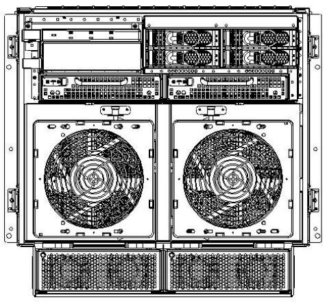
Figure 1-2 HP 9000 rp7420 server (without front bezel)
System Backplane
The system backplane is comprised of the system clock generation logic, the system reset generation logic, DC-to-DC converters, power monitor logic, and two Local Bus Adapter (LBA) link-to-PCI converter ASICs. It also includes connectors for attaching the cell boards, the PCI-X backplane, Management Processor (MP) Core I/O MP/SCSI boards, SCSI cables, bulk power, chassis fans, the front panel display, intrusion switches, and the system scan card. Unlike the Superdome or rp8400 servers, there are no Crossbar Chips (XBC) on the system backplane. The “crossbar-less”back-to-backCellController(CC)connectionincreasesperformanceandreduces costs.
Only half of the MP Core I/O board set connects to the system backplane. The MP/SCSI boards plug into the backplane, while the LAN/SCSI boards plug into the PCI-X backplane.
18 Overview

Figure 1-3 System Backplane Block Diagram
System Backplane to PCI-X Backplane Connectivity
The PCI-X backplane uses two connectors for the System Bus Adapter (SBA) link bus and two connectors for the high speed data signals and the manageability signals.
SBA link bus signals are routed through the system backplane to the CC on each corresponding cell board.
The high speed data signals are routed from the SBA chips on the PCI-X backplane to the two LBA PCI bus controllers on the system backplane.
Clocks and Reset
The system backplane contains reset and clock circuitry that propagates through the whole system. The central clocks drive all major chip set clocks. Therefore, these circuits represent a system-wide single point of failure.
I/O Subsystem
The cell board to the PCI-X board path runs from the CC to the SBA, from the SBA to the ropes, from the ropes to the LBA, and from the LBA to the PCI slots seen in Figure 1-4. The CC on cell board 0 and cell board 1 each communicate with individual SBAs over the SBA link. The SBA link consists of both an inbound and an outbound link with an effective bandwidth of approximately1GB/sec. TheSBAconvertstheSBAlinkprotocolinto“ropes.”Aropeisdefined as a high-speed, point-to-point data bus. The SBA can support up to 16 of these high-speed bi-directional rope links for a total aggregate bandwidth of approximately 4 GB/sec. Each LBA acts as a bus bridge, supporting either one or two ropes and capable of driving 33 Mhz or 66 Mhz for PCI cards. The LBAs can also drive at 66 Mhz or 133 Mhz for PCI-X cards.
Introduction 19

Figure 1-4 PCI-X Board to Cell Board Block Diagram

 NOTE: PCI-X slots 1 through 7 are dual rope slots, while slot 8 is a single rope slot.
ThePCI-XbackplaneistheprimaryI/OinterfaceforHP9000rp7420servers. Itprovidessixteen 64-bit, hot-plug PCI/PCI-X slots. Fourteen of the slots have dual ropes connected to the LBA chips.TheremainingtwoslotshaveasingleropeconnectedtoeachLBAchip.Eachofthesixteen slots are capable of 66 MHz/33 MHz PCI or 133 MHz/66 MHz PCI-X. All sixteen PCI slots are keyed for 3.3-volt connectors (accepting both Universal and 3.3-V cards). The PCI-X backplane does not provide any 5-volt slots for the I/O cards. For more details, see Table 1-1.
The PCI-X backplane is physically one board but behaves like two independent partitions. SBA 0 and its associated LBAs and eight PCI-X slots form one I/0 partition. SBA 1 and its associated LBAsandeightPCI-XslotsformtheotherI/0partition. OneI/Opartitioncanbepowereddown separate from the other I/O partition.
Table 1-1 PCI-X Slot Types
I/O Partition |
Slot |
Device1 |
0 |
8 |
PCI (33 or 66 MHz) / PCI-X (66 or 133 MHz) 64-bit, 3.3V connector, hot plug slot |
0 |
7 |
PCI (33 or 66 MHz) / PCI-X (66 or 133 MHz) 64-bit, 3.3V connector, hot plug slot |
0 |
6 |
PCI (33 or 66 MHz) / PCI-X (66 or 133 MHz) 64-bit, 3.3V connector, hot plug slot |
0 |
5 |
PCI (33 or 66 MHz) / PCI-X (66 or 133 MHz) 64-bit, 3.3V connector, hot plug slot |
20 Overview
 Table 1-1 PCI-X Slot Types (continued)
I/O Partition |
Slot |
Device1 |
0 |
4 |
PCI (33 or 66 MHz) / PCI-X (66 or 133 MHz) 64-bit, 3.3V connector, hot plug slot |
0 |
3 |
PCI (33 or 66 MHz) / PCI-X (66 or 133 MHz) 64-bit, 3.3V connector, hot plug slot |
0 |
2 |
PCI (33 or 66 MHz) / PCI-X (66 or 133 MHz) 64-bit, 3.3V connector, hot plug slot |
0 |
1 |
PCI (33 or 66 MHz) / PCI-X (66 or 133 MHz) 64-bit, 3.3V connector, hot plug slot |
1 |
8 |
PCI (33 or 66 MHz) / PCI-X (66 or 133 MHz) 64-bit, 3.3V connector, hot plug slot |
1 |
7 |
PCI (33 or 66 MHz) / PCI-X (66 or 133 MHz) 64-bit, 3.3V connector, hot plug slot |
1 |
6 |
PCI (33 or 66 MHz) / PCI-X (66 or 133 MHz) 64-bit, 3.3V connector, hot plug slot |
1 |
5 |
PCI (33 or 66 MHz) / PCI-X (66 or 133 MHz) 64-bit, 3.3V connector, hot plug slot |
1 |
4 |
PCI (33 or 66 MHz) / PCI-X (66 or 133 MHz) 64-bit, 3.3V connector, hot plug slot |
1 |
3 |
PCI (33 or 66 MHz) / PCI-X (66 or 133 MHz) 64-bit, 3.3V connector, hot plug slot |
1 |
2 |
PCI (33 or 66 MHz) / PCI-X (66 or 133 MHz) 64-bit, 3.3V connector, hot plug slot |
1 |
1 |
PCI (33 or 66 MHz) / PCI-X (66 or 133 MHz) 64-bit, 3.3V connector, hot plug slot |
1IftheslotisusedasaPCIslot,eitherthe33MHzor66MHzPCIfrequencyissupported. IftheslotisusedasaPCI-X slot, either the 66 MHz or 133 MHz PCI-X frequency is supported.
Detailed HP 9000 rp7420 Server Description
Figure 1-5 HP 9000 rp7420 server 8-Socket Block Diagram
Detailed HP 9000 rp7420 Server Description |
21 |
Cell Board
The cell board contains several hardware blocks connected by several data buses. The major hardware blocks are the Central Processor Units (CPUs), the Cell Controller, the Memory Controllers, and the Memory. Minor hardware blocks include Clock Distribution, Power Distribution,ResetCircuit,andPlatformDependentHardware(PDH)RiserBoardInterface.The busesincludetwoFrontSideBuses(FBS0andFBS1),aMemory(MID)bus,aCrossbar(XB)bus, and an I/O bus. All these blocks come together at the CC chip.
Figure 1-6 Cell Board
The HP 9000 rp7420 server has a 48-V distributed power system and receives the 48-V power from the system backplane board. The cell board contains DC-to-DC converters to generate the requiredvoltagerails.TheDC-to-DCconvertersonthecellboarddonotprovideN+1redundancy.
Because of space limitations on the cell board, the PDH/PDHC circuitry resides on a riser board that plugs into the cell board at a right angle. The cell board also includes clock circuits, test circuits, and de-coupling capacitors.
Figure 1-7 shows a simplified view of the memory subsystem. It consists of two independent accesspaths,eachpathhavingitsownaddressbus,controlbus,databus,andDIMMs.Inpractice, the CC runs the two paths 180 degrees out of phase with respect to each other to facilitate pipelining in the CC. Address and control signals are fanned out through register ports to the synchronous dynamic random access memory (SDRAM) on the DIMMs.
22 Overview
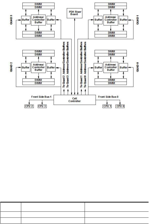
Figure 1-7 Memory Subsystem
PDH Riser Board
ThePlatformDependantHardwareRiserboardisadaughtercardforthecellboard. Itcontains a micro-processor memory interface microcircuit, processor-dependent hardware including the processor-dependent code (PDC), flash memory, and a manageability microcontroller, called thePlatformDependantHardwareController(PDHC)withassociatedcircuitry.ThePDHobtains cell board configuration information from cell board signals and from the LPM on the cell.
The PDH riser board contains circuitry that the cell board requires to function and, therefore, each cell board must have a PDH riser installed before it is added to a server.
Central Processor Units
The cell board can hold up to eight (four dual-core) CPUs and can be populated with CPUs in increments of two CPUs. On a cell board, the processors must be the same type and speed. Two CPUs is the minimum configuration allowed on the HP 9000 rp7420 server. There are two Frontside Buses (FBS), one for sockets 0 and 1, and one for sockets 2 and 3. Each FBS must have either a CPU or a terminator at the end of the bus or the board does not operate properly. There cannot be a terminator board in socket 1 or socket 3 locations. For the CPU load order that must be maintained when adding CPUs to the cell board, see Table 1-2. For the locations on the cell board for installing CPUs, see Figure 1-8.
Table 1-2 Cell Board CPU Load Order
Number of |
Socket 0 Location |
Socket 1 Location |
Socket 2 Location |
Socket 3 Location |
CPUs Installed |
|
|
|
|
Two |
CPU installed |
Empty slot |
Terminator |
Empty |
Four |
CPU installed |
Empty slot |
CPU installed |
Empty |
Detailed HP 9000 rp7420 Server Description |
23 |

 Table 1-2 Cell Board CPU Load Order (continued)
Number of |
Socket 0 Location |
Socket 1 Location |
Socket 2 Location |
Socket 3 Location |
CPUs Installed |
|
|
|
|
Six |
CPU installed |
CPU or empty |
CPU installed |
Empty or CPU |
Eight |
CPU installed |
CPU installed |
CPU installed |
CPU installed |
Figure 1-8 CPU Locations on Cell Board
DIMMs
Custom designed by HP, each DIMM contains 36 x 4 SDRAM memory components similar to PC-133 memory, but qualified to run at 125 MHz. They have a low-voltage TTL interface. The CEC does not support traditional DRAMs.
The HP 9000 rp7420 server supports DIMMs with 256 MB, 512, MB, 1 GB, and 2 GB capacity. Table 1-3shows each DIMM supported with its associated capacity, the resulting total system capacity, and the memory component density.
DIMMsmustbeloadedinsetsoftwoatspecificlocations.Forbestperformance,HPrecommends loading sets of eight DIMMs.
Table 1-3 HP 9000 rp7420 server DIMMs
DIMM Capacity |
Total Capacity |
Memory Component Density |
256 MB |
8 GB |
32 Mb |
512 MB |
16 GB |
64 Mb |
1 GB |
32 GB |
128 Mb |
2 GB |
64 GB |
256 Mb |
4 GB |
128 GB |
512 Mb |
24 Overview

Main Memory Performance
Latencytomainmemoryisanimportantparameterindeterminingoverallsystemperformance.
Withmemorybusesrunningat125MHz,thelatencyforapagehitis8.5cycles(68ns),thelatency for a page closed is 11.5 cycles (92 ns), and the latency for a page miss is 14.5 cycles (116 ns).
Valid Memory Configurations
TheHP9000rp7420serveriscapableofsupportingaslittleas0.5GBofmainmemoryusingtwo 256 MB DIMMs installed on a single cell board and as much as 128 GB by filling all 16 DIMM slots on both cell boards with 4 GB DIMMs.
DIMMs must be loaded in sets of two at specified locations on the cell board. Two DIMMs are called a rank; two ranks would be equivalent to four DIMMs, three ranks would be six DIMMs, andsoon. TheDIMMsmustbethesamesizeinarank. TheDIMMsacrossallcellsinapartition shouldhaveidenticalmemoryloaded. Figure1-9 showstheDIMMslotlayoutonthecellboard. For DIMM load order, see Table 1-4.
Aquadseenin Figure1-9 isagroupingoffourDIMMs. Configurationswith8or16DIMMslots loaded are recommended. The DIMM sizes in a quad can be different but the DIMMs in a rank must be the same size.
Table 1-4 DIMM Load Order
Number of DIMMs Installed |
Action Taken |
DIMM Location on Cell |
Quad Location |
|
|
Board |
|
2 DIMMs = 1 Rank |
Install First |
0A and 0B |
Quad 0 |
4 DIMMs = 2 Ranks |
Add Second |
1A and 1B |
Quad 1 |
6 DIMMs = 3 Ranks |
Add Third |
2A and 2B |
Quad 2 |
8 DIMMs = 4 Ranks |
Add Fourth |
3A and 3B |
Quad 3 |
10 DIMMs = 5 Ranks |
Add Fifth |
4A and 4B |
Quad 0 |
12 DIMMs = 6 Ranks |
Add Sixth |
5A and 5B |
Quad 1 |
14 DIMMs = 7 Ranks |
Add Seventh |
6A and 6B |
Quad 2 |
16 DIMMs = 8 Ranks |
Add Last |
7A and 7B |
Quad 3 |
Detailed HP 9000 rp7420 Server Description |
25 |

Figure 1-9 DIMM Slot Layout
Cells and nPartitions
A cell board that has an I/O link to a bootable device and a console (usually supplied by an MP coreI/Ocard)isapotentialbootcell. ThecellthatcontainsthebootconsoleI/Opathisthecalled therootcell.Bothcellsarepotentialrootcells.TheprimaryordefaultrootcellinasinglenPartition system is the bottom cell (cell 1).
An nPartition (also called a Protection Domain) is a cell or cells running the same operating system and sharing processes and memory space among the components. Each nPartition must have one root cell and can contain both cells. The HP 9000 rp7420 server has only two possible nPartition configurations: single or dual. The additional cell that can be part of the nPartition does not require I/O links or MP core I/O cards.
In the single nPartition case, if two cells are present, either cell can be the root cell, assuming both cells have MP core I/O functionality present. If only one cell is present, that cell is the root cell (and should be cell 1).
InthedualnPartitioncase(twocellsrequired),eachnPartitionconsistsofonecell,andeachcell must be a root cell. The ability to interconnect two cells in one nPartition or isolate the cells in a dualnPartitionsystemprovidessystemconfigurationflexibility.Systempartitioningisconfigured by the system MP.
NOTE: Partition configuration information is available on the HP website at http:// docs.hp.com. For more detail, see the HP Systems Partition Guide: Administration for nPartitions.
Internal Disk Devices for the HP 9000 rp7420 server
In an HP 9000 rp7420 server, the top internal disk drives connect to cell 1 through the core I/O for cell 1. Both of the bottom disk drives connect to cell 0 through the core I/O for cell 0.
The CD/DVD/DAT drive connects to cell 1 through the core I/O card for cell 1.
26 Overview

Figure 1-10 Internal Disks
MP/SCSI MP Core I/O Board
The HP 9000 rp7420 server accommodates two sets of MP Core I/O functionality. Each MP/SCSI core I/O board set consists of a MP/SCSI board and a Procurium LAN/SCSI board. At least one MP/SCSI board is required (independent of partitions). An additional MP/SCSI board can be added as well (and is required in a dual partition system). Both MP/SCSI boards are oriented vertically and plug into the system backplane. The MP/SCSI board incorporates a dual channel Ultra160 SCSI controller.
Procurium LAN/SCSI Board
AtleastoneProcuriumLAN/SCSIboardisrequiredfortheminimumsystemconfiguration;two arerequiredinadualpartitionsystem. TheProcuriumboardisastandardPCIformfactorcard with PCI card edge connectors. The PCI-X backplane has one slot location reserved for the required Procurium board and another that can accommodate either a Procurium board or any other supported add-in PCI-X card. The Procurium board is hot-pluggable.
Mass Storage (Disk) Backplane
Internal mass storage connections (to disks) are routed on the mass storage backplane, having connectors and termination circuitry. All disks are hot-pluggable. The HP 9000 rp7420 server accommodates one internal, removable media device. Therefore, only one power connector for aremovablemediadeviceisrequiredonthemassstoragebackplane.Themassstoragebackplane incorporates a circuit that enables power to the internal removable media device to be programmatically cycled.
Detailed HP 9000 rp7420 Server Description |
27 |
Server Description
Dimensions
The dimensions of the HP 9000 rp7420 server are as follows:
•Width: 44.45 cm (17.5 inches), constrained by EIA standard 19 inch racks
•Depth: Defined by cable management constraints to fit into standard 36-inch deep racks (Rittal/Compaq, Rosebowl I):
25.5 inches from front rack column to PCI connector surface
26.7 inches from front rack column to MP Core I/O connector surface
30 inches overall package dimension, including 2.7 inches protruding in front of the front rack columns
•Height:10U–0.54cm=43.91cm(17.287inches).Thisistheappropriateheightforaproduct that consumes 10U of rack height while allowing adequate clearance between products directly above and below this product. Fitting four server units per 2 m rack and upgrade of current 10U height products in the future are the main height constraints.
System Chassis
The mass storage section located in the front enables access to removable mass storage devices withoutremovalofthebezel(notshown).Thisisespeciallyhelpfulwhenthesystemismounted in the lowest position in a rack. The mass storage bay accommodates one 5.25-inch removable media device and up to four 3.5-inch hard drives. The front panel display board, containing LEDsandthesystempowerswitch,islocateddirectlyabovethe5.25-inchremovablemediabay.
Below the mass storage section and behind a removable bezel are two PCI DC-to-DC power converters.
TheBPSsectionispartitionedbyasealedmetallicenclosurelocatedinthebottomofthepackage. This enclosure houses the N+1 fully redundant BPS.
28 Overview
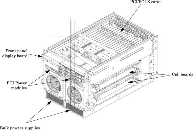
Figure 1-11 Right-Front View of HP 9000 rp7420 server
The PCI-X card section, located toward the rear, is accessed by removing the top cover.
ThePCIOLRfanmodulesarelocatedinfrontofthePCI-Xcards.Thesesix9.2-cmfansarehoused in plastic carriers. They are configured in two rows of three fans.
The MP/SCSI MP core I/O boards are positioned vertically at the rear of the chassis.
The PCI-X card bulkhead connectors are located in the top rear portion of the chassis.
FourOLRsystemfanmodules,externallyattachedtothechassis,are15-cm(6.5-inch)fans. Two fans are mounted on the front surface of the chassis and two are mounted on the rear surface. Thetwohot-pluggableN+1redundantBPSprovideawideinputvoltagerange.Theyareinstalled in the front of the chassis, directly under the front fans.
A cable harness that connects from the rear of the BPSs to the system backplane provides DC power distribution.
Access the system backplane by removing the left side cover. The system backplane inserts by a guide/insertion mechanism using a single large jack screw assembly.
SCSI ribbon-cable assemblies route from the mass storage area to the backside of the system backplane and to the Procurium PCI MP core I/O card.
Access the cell boards from the right side of the chassis behind the removable side cover.
Server Description |
29 |
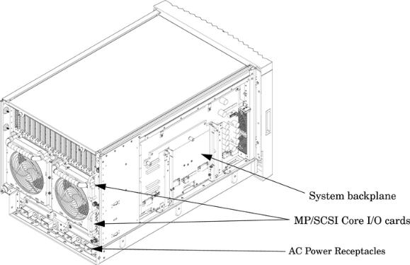
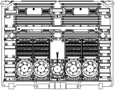
Figure 1-12 Left-Rear View of HP 9000 rp7420 server
30 Overview
Loading...