


 Loading...
User Service Guide
HP 9000 rp3410 and HP 9000 rp3440
Manufacturing Part Number: A7137-96008-ed5
Fifth Edition
September 2008
© Copyright 2003-2008 Hewlett-Packard Development Company, L.P.

Legal Notices
Copyright Notices. © Copyright 2003-2008 Hewlett-Packard Development Company, L.P.
The information contained herein is subject to change without notice. The only warranties for HP products and services are set forth in the express warranty statements accompanying such products and services. Nothing herein should be construed as constituting an additional warranty. HP shall not be liable for technical or editorial errors or omissions contained herein.
Printed in U.S.A.
Intel, Pentium, Intel Inside, Itanium, and the Intel Inside logo are trademarks or registered trademarks of Intel Corporation or its subsidiaries in the United States and other countries.
Linux is a U.S. registered trademark of Linus Torvalds.
2

Contents
1. Overview
HP 9000 rp3410 and rp3440 Server Views. . . . . . . . . . . . . . . . . . . . . . . . . . . . . . . . . . . . . . . . . . . . . . . . 20
Detailed Server Description . . . . . . . . . . . . . . . . . . . . . . . . . . . . . . . . . . . . . . . . . . . . . . . . . . . . . . . . . . . 22
Processor . . . . . . . . . . . . . . . . . . . . . . . . . . . . . . . . . . . . . . . . . . . . . . . . . . . . . . . . . . . . . . . . . . . . . . . . . 22
Memory . . . . . . . . . . . . . . . . . . . . . . . . . . . . . . . . . . . . . . . . . . . . . . . . . . . . . . . . . . . . . . . . . . . . . . . . . . 22
PCI Riser . . . . . . . . . . . . . . . . . . . . . . . . . . . . . . . . . . . . . . . . . . . . . . . . . . . . . . . . . . . . . . . . . . . . . . . . . 23
Internal Core I/O. . . . . . . . . . . . . . . . . . . . . . . . . . . . . . . . . . . . . . . . . . . . . . . . . . . . . . . . . . . . . . . . . . . 23
External Core I/O . . . . . . . . . . . . . . . . . . . . . . . . . . . . . . . . . . . . . . . . . . . . . . . . . . . . . . . . . . . . . . . . . . 23
Power Supply Unit . . . . . . . . . . . . . . . . . . . . . . . . . . . . . . . . . . . . . . . . . . . . . . . . . . . . . . . . . . . . . . . . . 23
System Board Manageability . . . . . . . . . . . . . . . . . . . . . . . . . . . . . . . . . . . . . . . . . . . . . . . . . . . . . . . . . 23
Enhanced Server Manageability Using the Integrity iLO MP . . . . . . . . . . . . . . . . . . . . . . . . . . . . . . 24
Hard Disk Drives . . . . . . . . . . . . . . . . . . . . . . . . . . . . . . . . . . . . . . . . . . . . . . . . . . . . . . . . . . . . . . . . . . 24
Internal RAID . . . . . . . . . . . . . . . . . . . . . . . . . . . . . . . . . . . . . . . . . . . . . . . . . . . . . . . . . . . . . . . . . . . . . 24
Firmware . . . . . . . . . . . . . . . . . . . . . . . . . . . . . . . . . . . . . . . . . . . . . . . . . . . . . . . . . . . . . . . . . . . . . . . . . 24
Dimensions and Values . . . . . . . . . . . . . . . . . . . . . . . . . . . . . . . . . . . . . . . . . . . . . . . . . . . . . . . . . . . . . 25
System Board . . . . . . . . . . . . . . . . . . . . . . . . . . . . . . . . . . . . . . . . . . . . . . . . . . . . . . . . . . . . . . . . . . . . . 25
Controls, Ports, and LEDs . . . . . . . . . . . . . . . . . . . . . . . . . . . . . . . . . . . . . . . . . . . . . . . . . . . . . . . . . . . . . 35
Control Panel . . . . . . . . . . . . . . . . . . . . . . . . . . . . . . . . . . . . . . . . . . . . . . . . . . . . . . . . . . . . . . . . . . . . . 35
Additional Controls and Indicators . . . . . . . . . . . . . . . . . . . . . . . . . . . . . . . . . . . . . . . . . . . . . . . . . . . . 37
Rear Panel . . . . . . . . . . . . . . . . . . . . . . . . . . . . . . . . . . . . . . . . . . . . . . . . . . . . . . . . . . . . . . . . . . . . . . . . 38
Powering the Server On and Off . . . . . . . . . . . . . . . . . . . . . . . . . . . . . . . . . . . . . . . . . . . . . . . . . . . . . . . . 44
Power States . . . . . . . . . . . . . . . . . . . . . . . . . . . . . . . . . . . . . . . . . . . . . . . . . . . . . . . . . . . . . . . . . . . . . . 44
Powering On the Server . . . . . . . . . . . . . . . . . . . . . . . . . . . . . . . . . . . . . . . . . . . . . . . . . . . . . . . . . . . . . 45
Powering Off the Server . . . . . . . . . . . . . . . . . . . . . . . . . . . . . . . . . . . . . . . . . . . . . . . . . . . . . . . . . . . . . 45
2. System Specifications
System Configuration . . . . . . . . . . . . . . . . . . . . . . . . . . . . . . . . . . . . . . . . . . . . . . . . . . . . . . . . . . . . . . . . 47
Dimensions and Values . . . . . . . . . . . . . . . . . . . . . . . . . . . . . . . . . . . . . . . . . . . . . . . . . . . . . . . . . . . . . . . 48
Grounding. . . . . . . . . . . . . . . . . . . . . . . . . . . . . . . . . . . . . . . . . . . . . . . . . . . . . . . . . . . . . . . . . . . . . . . . . . 49
Electrical Specifications. . . . . . . . . . . . . . . . . . . . . . . . . . . . . . . . . . . . . . . . . . . . . . . . . . . . . . . . . . . . . . . 49
AC Power Cords . . . . . . . . . . . . . . . . . . . . . . . . . . . . . . . . . . . . . . . . . . . . . . . . . . . . . . . . . . . . . . . . . . . 49
Circuit Breaker . . . . . . . . . . . . . . . . . . . . . . . . . . . . . . . . . . . . . . . . . . . . . . . . . . . . . . . . . . . . . . . . . . . . 50
System Power Specifications . . . . . . . . . . . . . . . . . . . . . . . . . . . . . . . . . . . . . . . . . . . . . . . . . . . . . . . . . 50
Power and Cooling . . . . . . . . . . . . . . . . . . . . . . . . . . . . . . . . . . . . . . . . . . . . . . . . . . . . . . . . . . . . . . . . . 51
Environmental Specifications . . . . . . . . . . . . . . . . . . . . . . . . . . . . . . . . . . . . . . . . . . . . . . . . . . . . . . . . . . 51
Operating Environment . . . . . . . . . . . . . . . . . . . . . . . . . . . . . . . . . . . . . . . . . . . . . . . . . . . . . . . . . . . . . 52
Environmental Temperature Sensor . . . . . . . . . . . . . . . . . . . . . . . . . . . . . . . . . . . . . . . . . . . . . . . . . . . 52
Nonoperating Environment . . . . . . . . . . . . . . . . . . . . . . . . . . . . . . . . . . . . . . . . . . . . . . . . . . . . . . . . . . 52
Cooling. . . . . . . . . . . . . . . . . . . . . . . . . . . . . . . . . . . . . . . . . . . . . . . . . . . . . . . . . . . . . . . . . . . . . . . . . . . 52
Acoustic Noise Specification. . . . . . . . . . . . . . . . . . . . . . . . . . . . . . . . . . . . . . . . . . . . . . . . . . . . . . . . . . 53
Physical and Environmental Specifications . . . . . . . . . . . . . . . . . . . . . . . . . . . . . . . . . . . . . . . . . . . . . . . 54
3. Installing the System
Introduction . . . . . . . . . . . . . . . . . . . . . . . . . . . . . . . . . . . . . . . . . . . . . . . . . . . . . . . . . . . . . . . . . . . . . . . . 55
Server Views . . . . . . . . . . . . . . . . . . . . . . . . . . . . . . . . . . . . . . . . . . . . . . . . . . . . . . . . . . . . . . . . . . . . . . 56
Detailed Server Description . . . . . . . . . . . . . . . . . . . . . . . . . . . . . . . . . . . . . . . . . . . . . . . . . . . . . . . . . . 58
3

Contents
Safety Information . . . . . . . . . . . . . . . . . . . . . . . . . . . . . . . . . . . . . . . . . . . . . . . . . . . . . . . . . . . . . . . . . 59 Installation Sequence and Checklist . . . . . . . . . . . . . . . . . . . . . . . . . . . . . . . . . . . . . . . . . . . . . . . . . . . 60 Unpacking and Inspecting the Server . . . . . . . . . . . . . . . . . . . . . . . . . . . . . . . . . . . . . . . . . . . . . . . . . . . 61 Verifying Site Preparation . . . . . . . . . . . . . . . . . . . . . . . . . . . . . . . . . . . . . . . . . . . . . . . . . . . . . . . . . . . 61 Inspecting the Shipping Containers for Damage . . . . . . . . . . . . . . . . . . . . . . . . . . . . . . . . . . . . . . . . . 61 Unpacking the Server. . . . . . . . . . . . . . . . . . . . . . . . . . . . . . . . . . . . . . . . . . . . . . . . . . . . . . . . . . . . . . . 61 Checking the Inventory . . . . . . . . . . . . . . . . . . . . . . . . . . . . . . . . . . . . . . . . . . . . . . . . . . . . . . . . . . . . . 61 Returning Damaged Equipment . . . . . . . . . . . . . . . . . . . . . . . . . . . . . . . . . . . . . . . . . . . . . . . . . . . . . . 62 Unloading the Server with a Lifter . . . . . . . . . . . . . . . . . . . . . . . . . . . . . . . . . . . . . . . . . . . . . . . . . . . . 62 Installing Additional Components . . . . . . . . . . . . . . . . . . . . . . . . . . . . . . . . . . . . . . . . . . . . . . . . . . . . . . 63 Removing and Replacing Server Covers and Bezels. . . . . . . . . . . . . . . . . . . . . . . . . . . . . . . . . . . . . . . 63 Installing Internal Hard Disk Drives . . . . . . . . . . . . . . . . . . . . . . . . . . . . . . . . . . . . . . . . . . . . . . . . . . 73 Installing a DVD Drive. . . . . . . . . . . . . . . . . . . . . . . . . . . . . . . . . . . . . . . . . . . . . . . . . . . . . . . . . . . . . . 77 Removing and Replacing Airflow Guides . . . . . . . . . . . . . . . . . . . . . . . . . . . . . . . . . . . . . . . . . . . . . . . 78 Installing Additional System Memory. . . . . . . . . . . . . . . . . . . . . . . . . . . . . . . . . . . . . . . . . . . . . . . . . . 84 Removing and Replacing the PCI Card Cage . . . . . . . . . . . . . . . . . . . . . . . . . . . . . . . . . . . . . . . . . . . . 88 Installing PCI Cards. . . . . . . . . . . . . . . . . . . . . . . . . . . . . . . . . . . . . . . . . . . . . . . . . . . . . . . . . . . . . . . . 90 Installing an Additional Power Supply . . . . . . . . . . . . . . . . . . . . . . . . . . . . . . . . . . . . . . . . . . . . . . . . . 92 Installing an Additional Processor Module . . . . . . . . . . . . . . . . . . . . . . . . . . . . . . . . . . . . . . . . . . . . . . 93 Replacing the System Battery . . . . . . . . . . . . . . . . . . . . . . . . . . . . . . . . . . . . . . . . . . . . . . . . . . . . . . . 102 Installing the Server Into a Rack, Non-HP Rack, or Pedestal . . . . . . . . . . . . . . . . . . . . . . . . . . . . . . . 104 HP Rack. . . . . . . . . . . . . . . . . . . . . . . . . . . . . . . . . . . . . . . . . . . . . . . . . . . . . . . . . . . . . . . . . . . . . . . . . 104 Non-HP Rack. . . . . . . . . . . . . . . . . . . . . . . . . . . . . . . . . . . . . . . . . . . . . . . . . . . . . . . . . . . . . . . . . . . . . 104 Pedestal Mount . . . . . . . . . . . . . . . . . . . . . . . . . . . . . . . . . . . . . . . . . . . . . . . . . . . . . . . . . . . . . . . . . . . 104 Connecting the Cables . . . . . . . . . . . . . . . . . . . . . . . . . . . . . . . . . . . . . . . . . . . . . . . . . . . . . . . . . . . . . . . 105 AC Input Power. . . . . . . . . . . . . . . . . . . . . . . . . . . . . . . . . . . . . . . . . . . . . . . . . . . . . . . . . . . . . . . . . . . 105 Core I/O Connections . . . . . . . . . . . . . . . . . . . . . . . . . . . . . . . . . . . . . . . . . . . . . . . . . . . . . . . . . . . . . . 105 Applying Standby Power to the Server . . . . . . . . . . . . . . . . . . . . . . . . . . . . . . . . . . . . . . . . . . . . . . . . 106 Connecting to the LAN . . . . . . . . . . . . . . . . . . . . . . . . . . . . . . . . . . . . . . . . . . . . . . . . . . . . . . . . . . . . . 106 Console Setup. . . . . . . . . . . . . . . . . . . . . . . . . . . . . . . . . . . . . . . . . . . . . . . . . . . . . . . . . . . . . . . . . . . . . . 107 Setup Checklist . . . . . . . . . . . . . . . . . . . . . . . . . . . . . . . . . . . . . . . . . . . . . . . . . . . . . . . . . . . . . . . . . . . 107 Setup Flowchart . . . . . . . . . . . . . . . . . . . . . . . . . . . . . . . . . . . . . . . . . . . . . . . . . . . . . . . . . . . . . . . . . . 108 Preparation . . . . . . . . . . . . . . . . . . . . . . . . . . . . . . . . . . . . . . . . . . . . . . . . . . . . . . . . . . . . . . . . . . . . . . 109 Configuring the iLO MP LAN Using DHCP and DNS . . . . . . . . . . . . . . . . . . . . . . . . . . . . . . . . . . . . 110 Configuring the iLO MP LAN Using ARP Ping . . . . . . . . . . . . . . . . . . . . . . . . . . . . . . . . . . . . . . . . . 110 Configuring the iLO MP LAN Using the RS-232 Serial Port. . . . . . . . . . . . . . . . . . . . . . . . . . . . . . . 112 Logging In to the iLO MP. . . . . . . . . . . . . . . . . . . . . . . . . . . . . . . . . . . . . . . . . . . . . . . . . . . . . . . . . . . 114 Additional Setup . . . . . . . . . . . . . . . . . . . . . . . . . . . . . . . . . . . . . . . . . . . . . . . . . . . . . . . . . . . . . . . . . . 114 Accessing the Host Console . . . . . . . . . . . . . . . . . . . . . . . . . . . . . . . . . . . . . . . . . . . . . . . . . . . . . . . . . . . 116 Accessing the Host Console With the TUI - CO Command . . . . . . . . . . . . . . . . . . . . . . . . . . . . . . . . 116 Interacting with the iLO MP Using the Web GUI . . . . . . . . . . . . . . . . . . . . . . . . . . . . . . . . . . . . . . . 116 Accessing the Graphic Console Using VGA. . . . . . . . . . . . . . . . . . . . . . . . . . . . . . . . . . . . . . . . . . . . . 117 Powering the Server ON and OFF . . . . . . . . . . . . . . . . . . . . . . . . . . . . . . . . . . . . . . . . . . . . . . . . . . . . . 119 Power States . . . . . . . . . . . . . . . . . . . . . . . . . . . . . . . . . . . . . . . . . . . . . . . . . . . . . . . . . . . . . . . . . . . . . 119 Powering On the Server . . . . . . . . . . . . . . . . . . . . . . . . . . . . . . . . . . . . . . . . . . . . . . . . . . . . . . . . . . . . 119 Powering Off the Server . . . . . . . . . . . . . . . . . . . . . . . . . . . . . . . . . . . . . . . . . . . . . . . . . . . . . . . . . . . . 120
4

Contents
Booting the Operating System . . . . . . . . . . . . . . . . . . . . . . . . . . . . . . . . . . . . . . . . . . . . . . . . . . . . . . . . 121 Supported Operating System. . . . . . . . . . . . . . . . . . . . . . . . . . . . . . . . . . . . . . . . . . . . . . . . . . . . . . . . 121 Booting and Shutting Down HP-UX . . . . . . . . . . . . . . . . . . . . . . . . . . . . . . . . . . . . . . . . . . . . . . . . . . 121 Verifying the Server Configuration Using Boot Console Handler . . . . . . . . . . . . . . . . . . . . . . . . . . . 123 Troubleshooting . . . . . . . . . . . . . . . . . . . . . . . . . . . . . . . . . . . . . . . . . . . . . . . . . . . . . . . . . . . . . . . . . . . . 124 Troubleshooting Methodology . . . . . . . . . . . . . . . . . . . . . . . . . . . . . . . . . . . . . . . . . . . . . . . . . . . . . . . 124 Troubleshooting Using the Server Power Button . . . . . . . . . . . . . . . . . . . . . . . . . . . . . . . . . . . . . . . . 124 Server Does Not Power On. . . . . . . . . . . . . . . . . . . . . . . . . . . . . . . . . . . . . . . . . . . . . . . . . . . . . . . . . . 125 Operating System Does Not Boot . . . . . . . . . . . . . . . . . . . . . . . . . . . . . . . . . . . . . . . . . . . . . . . . . . . . 125 Operating System Boots with Problems . . . . . . . . . . . . . . . . . . . . . . . . . . . . . . . . . . . . . . . . . . . . . . . 126 Intermittent Server Problems . . . . . . . . . . . . . . . . . . . . . . . . . . . . . . . . . . . . . . . . . . . . . . . . . . . . . . . 126 DVD Problems. . . . . . . . . . . . . . . . . . . . . . . . . . . . . . . . . . . . . . . . . . . . . . . . . . . . . . . . . . . . . . . . . . . . 126 Hard Drive Problems . . . . . . . . . . . . . . . . . . . . . . . . . . . . . . . . . . . . . . . . . . . . . . . . . . . . . . . . . . . . . . 126 Console Problems . . . . . . . . . . . . . . . . . . . . . . . . . . . . . . . . . . . . . . . . . . . . . . . . . . . . . . . . . . . . . . . . . 126 Downloading and Installing the Latest Version of the Firmware . . . . . . . . . . . . . . . . . . . . . . . . . . . 127 Troubleshooting Using LED Indicators. . . . . . . . . . . . . . . . . . . . . . . . . . . . . . . . . . . . . . . . . . . . . . . . 127 Information to Collect Before You Contact Support . . . . . . . . . . . . . . . . . . . . . . . . . . . . . . . . . . . . . . 130
4. Booting the Operating System
Supported Operating System . . . . . . . . . . . . . . . . . . . . . . . . . . . . . . . . . . . . . . . . . . . . . . . . . . . . . . . . . 131 Booting and Shutting Down HP-UX . . . . . . . . . . . . . . . . . . . . . . . . . . . . . . . . . . . . . . . . . . . . . . . . . . . . 132 Standard HP-UX Booting Using Boot Console Handler. . . . . . . . . . . . . . . . . . . . . . . . . . . . . . . . . . . 132 Booting HP-UX in Single-User Mode . . . . . . . . . . . . . . . . . . . . . . . . . . . . . . . . . . . . . . . . . . . . . . . . . 133 Booting HP-UX in LVM Maintenance Mode . . . . . . . . . . . . . . . . . . . . . . . . . . . . . . . . . . . . . . . . . . . . 133 Shutting Down HP-UX . . . . . . . . . . . . . . . . . . . . . . . . . . . . . . . . . . . . . . . . . . . . . . . . . . . . . . . . . . . . . 133 Verifying the Server Configuration Using Boot Console Handler. . . . . . . . . . . . . . . . . . . . . . . . . . . . . 134
5. Troubleshooting
Troubleshooting Methodology . . . . . . . . . . . . . . . . . . . . . . . . . . . . . . . . . . . . . . . . . . . . . . . . . . . . . . . . . 135 Troubleshooting System Power . . . . . . . . . . . . . . . . . . . . . . . . . . . . . . . . . . . . . . . . . . . . . . . . . . . . . . . . 136 Using the Front Panel Power Button. . . . . . . . . . . . . . . . . . . . . . . . . . . . . . . . . . . . . . . . . . . . . . . . . . 136 Operating System Does Boot . . . . . . . . . . . . . . . . . . . . . . . . . . . . . . . . . . . . . . . . . . . . . . . . . . . . . . . . 136 Operating System Does Not Boot . . . . . . . . . . . . . . . . . . . . . . . . . . . . . . . . . . . . . . . . . . . . . . . . . . . . 137 Troubleshooting Using Online Support Tools . . . . . . . . . . . . . . . . . . . . . . . . . . . . . . . . . . . . . . . . . . . . 137 Support Tools Manager . . . . . . . . . . . . . . . . . . . . . . . . . . . . . . . . . . . . . . . . . . . . . . . . . . . . . . . . . . . . 137 Event Monitoring Service. . . . . . . . . . . . . . . . . . . . . . . . . . . . . . . . . . . . . . . . . . . . . . . . . . . . . . . . . . . 137 iLO MP . . . . . . . . . . . . . . . . . . . . . . . . . . . . . . . . . . . . . . . . . . . . . . . . . . . . . . . . . . . . . . . . . . . . . . . . . 138 Troubleshooting Using Offline Support Tools . . . . . . . . . . . . . . . . . . . . . . . . . . . . . . . . . . . . . . . . . . . . 140 Offline Diagnostic Environment (ODE). . . . . . . . . . . . . . . . . . . . . . . . . . . . . . . . . . . . . . . . . . . . . . . . 140 Identifying and Diagnosing Hardware Problems. . . . . . . . . . . . . . . . . . . . . . . . . . . . . . . . . . . . . . . . . . 141 Troubleshooting Using LEDs . . . . . . . . . . . . . . . . . . . . . . . . . . . . . . . . . . . . . . . . . . . . . . . . . . . . . . . . . 141 Power and System LEDs . . . . . . . . . . . . . . . . . . . . . . . . . . . . . . . . . . . . . . . . . . . . . . . . . . . . . . . . . . . 141 LAN LEDs . . . . . . . . . . . . . . . . . . . . . . . . . . . . . . . . . . . . . . . . . . . . . . . . . . . . . . . . . . . . . . . . . . . . . . . 142 System Board LEDs . . . . . . . . . . . . . . . . . . . . . . . . . . . . . . . . . . . . . . . . . . . . . . . . . . . . . . . . . . . . . . . 144 Cleaning Procedures . . . . . . . . . . . . . . . . . . . . . . . . . . . . . . . . . . . . . . . . . . . . . . . . . . . . . . . . . . . . . . . . 145
5

Contents
6. Removing and Replacing Components
Safety Information . . . . . . . . . . . . . . . . . . . . . . . . . . . . . . . . . . . . . . . . . . . . . . . . . . . . . . . . . . . . . . . . . . 147
Required Service Tools. . . . . . . . . . . . . . . . . . . . . . . . . . . . . . . . . . . . . . . . . . . . . . . . . . . . . . . . . . . . . . . 148
Location of Internal Components and Connectors. . . . . . . . . . . . . . . . . . . . . . . . . . . . . . . . . . . . . . . . . 149
Removing and Replacing Server Covers and Bezel . . . . . . . . . . . . . . . . . . . . . . . . . . . . . . . . . . . . . . . . 151
Accessing a Rack-Mount Server. . . . . . . . . . . . . . . . . . . . . . . . . . . . . . . . . . . . . . . . . . . . . . . . . . . . . . 151
Accessing Pedestal-Mount Server . . . . . . . . . . . . . . . . . . . . . . . . . . . . . . . . . . . . . . . . . . . . . . . . . . . . 156
Removing and Replacing System Fans . . . . . . . . . . . . . . . . . . . . . . . . . . . . . . . . . . . . . . . . . . . . . . . . . . 161
Removing a System Fan . . . . . . . . . . . . . . . . . . . . . . . . . . . . . . . . . . . . . . . . . . . . . . . . . . . . . . . . . . . . 161
Replacing a System Fan . . . . . . . . . . . . . . . . . . . . . . . . . . . . . . . . . . . . . . . . . . . . . . . . . . . . . . . . . . . . 163
Removing and Replacing the Power Supply . . . . . . . . . . . . . . . . . . . . . . . . . . . . . . . . . . . . . . . . . . . . . . 163
Removing the Power Supply . . . . . . . . . . . . . . . . . . . . . . . . . . . . . . . . . . . . . . . . . . . . . . . . . . . . . . . . 164
Replacing the Power Supply. . . . . . . . . . . . . . . . . . . . . . . . . . . . . . . . . . . . . . . . . . . . . . . . . . . . . . . . . 165
Removing and Replacing an Internal Hard Disk Drive. . . . . . . . . . . . . . . . . . . . . . . . . . . . . . . . . . . . . 166
Removing a Hard Disk Drive . . . . . . . . . . . . . . . . . . . . . . . . . . . . . . . . . . . . . . . . . . . . . . . . . . . . . . . . 166
Replacing a Hard Disk Drive . . . . . . . . . . . . . . . . . . . . . . . . . . . . . . . . . . . . . . . . . . . . . . . . . . . . . . . . 168
Removing and Replacing Airflow Guides . . . . . . . . . . . . . . . . . . . . . . . . . . . . . . . . . . . . . . . . . . . . . . . . 170
Removing and Replacing the Memory Airflow Guide. . . . . . . . . . . . . . . . . . . . . . . . . . . . . . . . . . . . . 171
Removing and Replacing the Processor Airflow Guide. . . . . . . . . . . . . . . . . . . . . . . . . . . . . . . . . . . . 172
Removing and Replacing System Memory . . . . . . . . . . . . . . . . . . . . . . . . . . . . . . . . . . . . . . . . . . . . . . . 177
Supported DIMM Sizes . . . . . . . . . . . . . . . . . . . . . . . . . . . . . . . . . . . . . . . . . . . . . . . . . . . . . . . . . . . . 177
rp3410 Memory Configuration. . . . . . . . . . . . . . . . . . . . . . . . . . . . . . . . . . . . . . . . . . . . . . . . . . . . . . . 178
rp3440 Memory Configuration. . . . . . . . . . . . . . . . . . . . . . . . . . . . . . . . . . . . . . . . . . . . . . . . . . . . . . . 179
System Firmware Requirements . . . . . . . . . . . . . . . . . . . . . . . . . . . . . . . . . . . . . . . . . . . . . . . . . . . . . 179
Replacing Deallocated Memory Ranks . . . . . . . . . . . . . . . . . . . . . . . . . . . . . . . . . . . . . . . . . . . . . . . . 180
Removing System Memory. . . . . . . . . . . . . . . . . . . . . . . . . . . . . . . . . . . . . . . . . . . . . . . . . . . . . . . . . . 180
Installing System Memory . . . . . . . . . . . . . . . . . . . . . . . . . . . . . . . . . . . . . . . . . . . . . . . . . . . . . . . . . . 181
Removing and Replacing a Dual Processor Module. . . . . . . . . . . . . . . . . . . . . . . . . . . . . . . . . . . . . . . . 183
Removing a Dual Processor Module . . . . . . . . . . . . . . . . . . . . . . . . . . . . . . . . . . . . . . . . . . . . . . . . . . 183
Installing a Dual Processor Module. . . . . . . . . . . . . . . . . . . . . . . . . . . . . . . . . . . . . . . . . . . . . . . . . . . 190
Removing and Replacing the System Battery . . . . . . . . . . . . . . . . . . . . . . . . . . . . . . . . . . . . . . . . . . . . 198
Battery Notice . . . . . . . . . . . . . . . . . . . . . . . . . . . . . . . . . . . . . . . . . . . . . . . . . . . . . . . . . . . . . . . . . . . . 198
Removing the System Battery . . . . . . . . . . . . . . . . . . . . . . . . . . . . . . . . . . . . . . . . . . . . . . . . . . . . . . . 198
Replacing the System Battery . . . . . . . . . . . . . . . . . . . . . . . . . . . . . . . . . . . . . . . . . . . . . . . . . . . . . . . 199
Removing and Replacing the PCI Card Cage. . . . . . . . . . . . . . . . . . . . . . . . . . . . . . . . . . . . . . . . . . . . . 200
Removing the PCI Card Cage . . . . . . . . . . . . . . . . . . . . . . . . . . . . . . . . . . . . . . . . . . . . . . . . . . . . . . . 200
Replacing the PCI Card Cage . . . . . . . . . . . . . . . . . . . . . . . . . . . . . . . . . . . . . . . . . . . . . . . . . . . . . . . 202
Removing and Replacing PCI Cards. . . . . . . . . . . . . . . . . . . . . . . . . . . . . . . . . . . . . . . . . . . . . . . . . . . . 202
Removing a PCI or Graphics Card. . . . . . . . . . . . . . . . . . . . . . . . . . . . . . . . . . . . . . . . . . . . . . . . . . . . 203
Replacing a PCI or Graphics Card. . . . . . . . . . . . . . . . . . . . . . . . . . . . . . . . . . . . . . . . . . . . . . . . . . . . 204
Removing and Replacing the PCI Backplane . . . . . . . . . . . . . . . . . . . . . . . . . . . . . . . . . . . . . . . . . . . . . 205
Removing the PCI Backplane . . . . . . . . . . . . . . . . . . . . . . . . . . . . . . . . . . . . . . . . . . . . . . . . . . . . . . . 205
Replacing the PCI Backplane. . . . . . . . . . . . . . . . . . . . . . . . . . . . . . . . . . . . . . . . . . . . . . . . . . . . . . . . 206
Removing and Replacing a Removable Media Drive . . . . . . . . . . . . . . . . . . . . . . . . . . . . . . . . . . . . . . . 207
Removing a Removable Media Drive. . . . . . . . . . . . . . . . . . . . . . . . . . . . . . . . . . . . . . . . . . . . . . . . . . 208
Replacing a Removable Media Drive . . . . . . . . . . . . . . . . . . . . . . . . . . . . . . . . . . . . . . . . . . . . . . . . . . 208
6

Contents
Removing and Replacing the iLO MP Card . . . . . . . . . . . . . . . . . . . . . . . . . . . . . . . . . . . . . . . . . . . . . . 209 Removing the iLO MP Card . . . . . . . . . . . . . . . . . . . . . . . . . . . . . . . . . . . . . . . . . . . . . . . . . . . . . . . . . 209 Replacing the iLO MP card . . . . . . . . . . . . . . . . . . . . . . . . . . . . . . . . . . . . . . . . . . . . . . . . . . . . . . . . . 210 Removing and Replacing the iLO MP Card Battery . . . . . . . . . . . . . . . . . . . . . . . . . . . . . . . . . . . . . . . 211 Battery Notice . . . . . . . . . . . . . . . . . . . . . . . . . . . . . . . . . . . . . . . . . . . . . . . . . . . . . . . . . . . . . . . . . . . . 211 Removing the iLO MP Card Battery . . . . . . . . . . . . . . . . . . . . . . . . . . . . . . . . . . . . . . . . . . . . . . . . . . 211 Replacing the iLO MP Card Battery . . . . . . . . . . . . . . . . . . . . . . . . . . . . . . . . . . . . . . . . . . . . . . . . . . 212 Removing and Replacing the LED Status Panel . . . . . . . . . . . . . . . . . . . . . . . . . . . . . . . . . . . . . . . . . . 213 Removing the LED Status Panel . . . . . . . . . . . . . . . . . . . . . . . . . . . . . . . . . . . . . . . . . . . . . . . . . . . . . 213 Replacing the LED Status Panel . . . . . . . . . . . . . . . . . . . . . . . . . . . . . . . . . . . . . . . . . . . . . . . . . . . . . 213 Removing and Replacing the System Board. . . . . . . . . . . . . . . . . . . . . . . . . . . . . . . . . . . . . . . . . . . . . . 214 Removing the System Board . . . . . . . . . . . . . . . . . . . . . . . . . . . . . . . . . . . . . . . . . . . . . . . . . . . . . . . . 214 Replacing the System Board . . . . . . . . . . . . . . . . . . . . . . . . . . . . . . . . . . . . . . . . . . . . . . . . . . . . . . . . 217 Replacing the Resident System Board with a Replacement System Board . . . . . . . . . . . . . . . . . . . . . 221 Replacing a System Board . . . . . . . . . . . . . . . . . . . . . . . . . . . . . . . . . . . . . . . . . . . . . . . . . . . . . . . . . . 222 Removing and Replacing the Power Supply Interface Module . . . . . . . . . . . . . . . . . . . . . . . . . . . . . . . 223 Removing the Power Supply Interface Module . . . . . . . . . . . . . . . . . . . . . . . . . . . . . . . . . . . . . . . . . . 223 Replacing the Power Supply Interface Module . . . . . . . . . . . . . . . . . . . . . . . . . . . . . . . . . . . . . . . . . . 226 Removing and Replacing the Hard Disk Drive (SCSI) Backplane . . . . . . . . . . . . . . . . . . . . . . . . . . . . 227 Removing the Hard Drive Disk SCSI Backplane . . . . . . . . . . . . . . . . . . . . . . . . . . . . . . . . . . . . . . . . 227 Replacing the Hard Disk Drive SCSI Backplane . . . . . . . . . . . . . . . . . . . . . . . . . . . . . . . . . . . . . . . . 230
A. Replacement Parts
Parts Illustrations . . . . . . . . . . . . . . . . . . . . . . . . . . . . . . . . . . . . . . . . . . . . . . . . . . . . . . . . . . . . . . . . . . 232
Customer Self Repair. . . . . . . . . . . . . . . . . . . . . . . . . . . . . . . . . . . . . . . . . . . . . . . . . . . . . . . . . . . . . . . . 234
Replaceable Parts List . . . . . . . . . . . . . . . . . . . . . . . . . . . . . . . . . . . . . . . . . . . . . . . . . . . . . . . . . . . . . . . 236
B. Utilities
Boot Console Handler . . . . . . . . . . . . . . . . . . . . . . . . . . . . . . . . . . . . . . . . . . . . . . . . . . . . . . . . . . . . . . . 241 BCH Commands . . . . . . . . . . . . . . . . . . . . . . . . . . . . . . . . . . . . . . . . . . . . . . . . . . . . . . . . . . . . . . . . . . 241 iLO MP . . . . . . . . . . . . . . . . . . . . . . . . . . . . . . . . . . . . . . . . . . . . . . . . . . . . . . . . . . . . . . . . . . . . . . . . . . . 247
C. Physical and Environmental Specifications
Index . . . . . . . . . . . . . . . . . . . . . . . . . . . . . . . . . . . . . . . . . . . . . . . . . . . . . . . . . . . . . . . . . . . . . . 251
7

Contents
8

Tables
Table 1. Publishing History Details . . . . . . . . . . . . . . . . . . . . . . . . . . . . . . . . . . . . . . . . . . . . . . . . . . 15 Table 2. HP-UX 11i Releases . . . . . . . . . . . . . . . . . . . . . . . . . . . . . . . . . . . . . . . . . . . . . . . . . . . . . . . . 17 Table 1-1. Server Dimensions and Values. . . . . . . . . . . . . . . . . . . . . . . . . . . . . . . . . . . . . . . . . . . . . . 25 Table 1-2. Memory Array Capacities. . . . . . . . . . . . . . . . . . . . . . . . . . . . . . . . . . . . . . . . . . . . . . . . . . 29 Table 1-3. Internal Disk and DVD Paths . . . . . . . . . . . . . . . . . . . . . . . . . . . . . . . . . . . . . . . . . . . . . . 32 Table 1-4. Extended Core I/O Paths . . . . . . . . . . . . . . . . . . . . . . . . . . . . . . . . . . . . . . . . . . . . . . . . . . 32 Table 1-5. PCI I/O Paths . . . . . . . . . . . . . . . . . . . . . . . . . . . . . . . . . . . . . . . . . . . . . . . . . . . . . . . . . . . 33 Table 1-6. PCI I/O Hardware Paths . . . . . . . . . . . . . . . . . . . . . . . . . . . . . . . . . . . . . . . . . . . . . . . . . . 33 Table 1-7. Control Panel LEDs and Switches . . . . . . . . . . . . . . . . . . . . . . . . . . . . . . . . . . . . . . . . . . . 36 Table 1-8. Hot-Pluggable Disk Drive LED Definitions . . . . . . . . . . . . . . . . . . . . . . . . . . . . . . . . . . . 37 Table 1-9. DVD Drive LED Definitions. . . . . . . . . . . . . . . . . . . . . . . . . . . . . . . . . . . . . . . . . . . . . . . . 38 Table 1-10. Rear Panel Connectors and Switches . . . . . . . . . . . . . . . . . . . . . . . . . . . . . . . . . . . . . . . 39 Table 1-11. 10/100/1000 Base-T Ethernet LAN Connector LEDs . . . . . . . . . . . . . . . . . . . . . . . . . . . 40 Table 1-12. 10/100/1000 Base-T Ethernet LAN Connector Pinouts . . . . . . . . . . . . . . . . . . . . . . . . . 40 Table 1-13. USB Pinouts . . . . . . . . . . . . . . . . . . . . . . . . . . . . . . . . . . . . . . . . . . . . . . . . . . . . . . . . . . . 41 Table 1-14. SCSI Port Pinouts . . . . . . . . . . . . . . . . . . . . . . . . . . . . . . . . . . . . . . . . . . . . . . . . . . . . . . . 41 Table 1-15. iLO MP Card LAN LEDs . . . . . . . . . . . . . . . . . . . . . . . . . . . . . . . . . . . . . . . . . . . . . . . . . 43 Table 1-16. iLO MP Card LAN Connector Pinouts . . . . . . . . . . . . . . . . . . . . . . . . . . . . . . . . . . . . . . 44 Table 1-17. Power States . . . . . . . . . . . . . . . . . . . . . . . . . . . . . . . . . . . . . . . . . . . . . . . . . . . . . . . . . . . 44 Table 2-1. Minimum and Maximum System Configurations. . . . . . . . . . . . . . . . . . . . . . . . . . . . . . . 47 Table 2-2. Server Dimensions and Values. . . . . . . . . . . . . . . . . . . . . . . . . . . . . . . . . . . . . . . . . . . . . . 48 Table 2-3. Power Cords. . . . . . . . . . . . . . . . . . . . . . . . . . . . . . . . . . . . . . . . . . . . . . . . . . . . . . . . . . . . . 49 Table 2-4. System Power Specifications . . . . . . . . . . . . . . . . . . . . . . . . . . . . . . . . . . . . . . . . . . . . . . . 50 Table 2-5. Additional Component Power Consumption . . . . . . . . . . . . . . . . . . . . . . . . . . . . . . . . . . . 51 Table 2-6. Environmental Specifications . . . . . . . . . . . . . . . . . . . . . . . . . . . . . . . . . . . . . . . . . . . . . . 51 Table 2-7. Physical and Environmental Specifications . . . . . . . . . . . . . . . . . . . . . . . . . . . . . . . . . . . 54 Table 3-1. HP 9000 rp3410 and rp3440 Server Features. . . . . . . . . . . . . . . . . . . . . . . . . . . . . . . . . . 58 Table 3-2. Server Dimensions and Values. . . . . . . . . . . . . . . . . . . . . . . . . . . . . . . . . . . . . . . . . . . . . . 59 Table 3-3. Installation Sequence Checklist. . . . . . . . . . . . . . . . . . . . . . . . . . . . . . . . . . . . . . . . . . . . . 60 Table 3-4. Setup Checklist . . . . . . . . . . . . . . . . . . . . . . . . . . . . . . . . . . . . . . . . . . . . . . . . . . . . . . . . . 107 Table 3-5. Console Connection Matrix . . . . . . . . . . . . . . . . . . . . . . . . . . . . . . . . . . . . . . . . . . . . . . . 109 Table 3-6. LAN Configuration Methods . . . . . . . . . . . . . . . . . . . . . . . . . . . . . . . . . . . . . . . . . . . . . . 109 Table 3-7. ARP Ping Commands . . . . . . . . . . . . . . . . . . . . . . . . . . . . . . . . . . . . . . . . . . . . . . . . . . . . 111 Table 3-8. Power States . . . . . . . . . . . . . . . . . . . . . . . . . . . . . . . . . . . . . . . . . . . . . . . . . . . . . . . . . . . 119 Table 3-9. Server Power Button Functions When Server is On and at BCH . . . . . . . . . . . . . . . . . 124 Table 3-10. Server Power Button Functions When Server is On and OS is Running . . . . . . . . . . 125 Table 3-11. Server Power Button Functions When Server is Off . . . . . . . . . . . . . . . . . . . . . . . . . . 125 Table 3-12. Front Control Panel LED Definitions . . . . . . . . . . . . . . . . . . . . . . . . . . . . . . . . . . . . . . 128 Table 5-1. Power Button Functions . . . . . . . . . . . . . . . . . . . . . . . . . . . . . . . . . . . . . . . . . . . . . . . . . . 136 Table 5-2. ODE Commands . . . . . . . . . . . . . . . . . . . . . . . . . . . . . . . . . . . . . . . . . . . . . . . . . . . . . . . . 140 Table 5-3. System LED States. . . . . . . . . . . . . . . . . . . . . . . . . . . . . . . . . . . . . . . . . . . . . . . . . . . . . . 141 Table 5-4. 10/100/1000 Base-T Ethernet LAN Connector LEDs . . . . . . . . . . . . . . . . . . . . . . . . . . . 142 Table 5-5. iLO MP Card LAN LEDs . . . . . . . . . . . . . . . . . . . . . . . . . . . . . . . . . . . . . . . . . . . . . . . . . 143
9

Tables
Table 5-6. System Board LEDs . . . . . . . . . . . . . . . . . . . . . . . . . . . . . . . . . . . . . . . . . . . . . . . . . . . . . 145 Table 5-7. Cleaning . . . . . . . . . . . . . . . . . . . . . . . . . . . . . . . . . . . . . . . . . . . . . . . . . . . . . . . . . . . . . . 145 Table 6-1. Component Locations . . . . . . . . . . . . . . . . . . . . . . . . . . . . . . . . . . . . . . . . . . . . . . . . . . . . 149 Table 6-2. Connector Locations . . . . . . . . . . . . . . . . . . . . . . . . . . . . . . . . . . . . . . . . . . . . . . . . . . . . . 150 Table A-1. Customer Self Repair Information . . . . . . . . . . . . . . . . . . . . . . . . . . . . . . . . . . . . . . . . . 235 Table A-2. Replaceable Parts List . . . . . . . . . . . . . . . . . . . . . . . . . . . . . . . . . . . . . . . . . . . . . . . . . . . 236 Table B-1. BCH Main Menu, Submenus, and Commands . . . . . . . . . . . . . . . . . . . . . . . . . . . . . . . . 242 Table B-2. Boot Paths. . . . . . . . . . . . . . . . . . . . . . . . . . . . . . . . . . . . . . . . . . . . . . . . . . . . . . . . . . . . . 242 Table C-1. Physical and Environmental Specifications . . . . . . . . . . . . . . . . . . . . . . . . . . . . . . . . . . 249
10
Figures
Figure 1-1. HP 9000 rp3410 and rp3440 Servers - Front View . . . . . . . . . . . . . . . . . . . . . . . . . . . . . 20 Figure 1-2. HP 9000 rp3410 and rp3440 Servers - Front View with Bezel Removed . . . . . . . . . . . 20 Figure 1-3. HP 9000 rp3410 and rp3440 Servers - Rear View. . . . . . . . . . . . . . . . . . . . . . . . . . . . . . 21 Figure 1-4. HP 9000 rp3410 and rp3440 Servers - Pedestal Mount . . . . . . . . . . . . . . . . . . . . . . . . . 21 Figure 1-5. System Block Diagram . . . . . . . . . . . . . . . . . . . . . . . . . . . . . . . . . . . . . . . . . . . . . . . . . . . 26 Figure 1-6. Memory Block Diagram . . . . . . . . . . . . . . . . . . . . . . . . . . . . . . . . . . . . . . . . . . . . . . . . . . 28 Figure 1-7. Front View . . . . . . . . . . . . . . . . . . . . . . . . . . . . . . . . . . . . . . . . . . . . . . . . . . . . . . . . . . . . . 35 Figure 1-8. Control Panel LEDs and Buttons. . . . . . . . . . . . . . . . . . . . . . . . . . . . . . . . . . . . . . . . . . . 35 Figure 1-9. Hot-Pluggable Disk Drive LED Indicators . . . . . . . . . . . . . . . . . . . . . . . . . . . . . . . . . . . 37 Figure 1-10. DVD Drive . . . . . . . . . . . . . . . . . . . . . . . . . . . . . . . . . . . . . . . . . . . . . . . . . . . . . . . . . . . . 38 Figure 1-11. Rear View . . . . . . . . . . . . . . . . . . . . . . . . . . . . . . . . . . . . . . . . . . . . . . . . . . . . . . . . . . . . 38 Figure 1-12. 10/100/1000 Base-T Ethernet LAN Connector LEDs . . . . . . . . . . . . . . . . . . . . . . . . . . 39 Figure 1-13. Dual USB Port Connector. . . . . . . . . . . . . . . . . . . . . . . . . . . . . . . . . . . . . . . . . . . . . . . . 40 Figure 1-14. Single USB Port . . . . . . . . . . . . . . . . . . . . . . . . . . . . . . . . . . . . . . . . . . . . . . . . . . . . . . . 41 Figure 1-15. SCSI Port, Ultra 3, 68-Pin . . . . . . . . . . . . . . . . . . . . . . . . . . . . . . . . . . . . . . . . . . . . . . . 41 Figure 1-16. iLO MP Card LAN LEDs . . . . . . . . . . . . . . . . . . . . . . . . . . . . . . . . . . . . . . . . . . . . . . . . 43 Figure 3-1. HP 9000 rp3410/rp3440 Server (Front View) . . . . . . . . . . . . . . . . . . . . . . . . . . . . . . . . . 56 Figure 3-2. HP 9000 rp3410/rp3440 Server (Front View with Bezel Removed) . . . . . . . . . . . . . . . . 56 Figure 3-3. HP 9000 rp3410/rp3440 Server (Rear View) . . . . . . . . . . . . . . . . . . . . . . . . . . . . . . . . . . 56 Figure 3-4. HP 9000 rp3410/rp3440 Server (Pedestal Mount) . . . . . . . . . . . . . . . . . . . . . . . . . . . . . 57 Figure 3-5. Release the Rack Latches . . . . . . . . . . . . . . . . . . . . . . . . . . . . . . . . . . . . . . . . . . . . . . . . 64 Figure 3-6. Removing and Replacing the Top Cover on a Rack-Mounted Server . . . . . . . . . . . . . . 65 Figure 3-7. Aligning the Top Cover . . . . . . . . . . . . . . . . . . . . . . . . . . . . . . . . . . . . . . . . . . . . . . . . . . 65 Figure 3-8. Closing the Top Cover . . . . . . . . . . . . . . . . . . . . . . . . . . . . . . . . . . . . . . . . . . . . . . . . . . . 66 Figure 3-9. Front Bezel Retaining Clip . . . . . . . . . . . . . . . . . . . . . . . . . . . . . . . . . . . . . . . . . . . . . . . 66 Figure 3-10. Replacing the Front Bezel . . . . . . . . . . . . . . . . . . . . . . . . . . . . . . . . . . . . . . . . . . . . . . . 67 Figure 3-11. Removing the Side Cover on a Pedestal-Mounted Server . . . . . . . . . . . . . . . . . . . . . . 68 Figure 3-12. Removing the Top Cover on a Pedestal-Mounted Server. . . . . . . . . . . . . . . . . . . . . . . 69 Figure 3-13. Top Cover Alignment Mark . . . . . . . . . . . . . . . . . . . . . . . . . . . . . . . . . . . . . . . . . . . . . . 70 Figure 3-14. Replacing the Top Cover on a Pedestal-Mounted Server. . . . . . . . . . . . . . . . . . . . . . . 70 Figure 3-15. Replacing the Side Cover on a Pedestal-Mounted Server . . . . . . . . . . . . . . . . . . . . . . 71 Figure 3-16. Removing the Front Bezel on a Pedestal-Mounted Server . . . . . . . . . . . . . . . . . . . . . . 72 Figure 3-17. Aligning the Pedestal Front Bezel . . . . . . . . . . . . . . . . . . . . . . . . . . . . . . . . . . . . . . . . . 73 Figure 3-18. Front View of the HP 9000 rp3410/rp3440 Server . . . . . . . . . . . . . . . . . . . . . . . . . . . . 74 Figure 3-19. Filler Removal from Slot 1. . . . . . . . . . . . . . . . . . . . . . . . . . . . . . . . . . . . . . . . . . . . . . . 75 Figure 3-20. Disk Drive Installation in Slot 3 . . . . . . . . . . . . . . . . . . . . . . . . . . . . . . . . . . . . . . . . . . 75 Figure 3-21. Hard Drive Lock. . . . . . . . . . . . . . . . . . . . . . . . . . . . . . . . . . . . . . . . . . . . . . . . . . . . . . . 76 Figure 3-22. DVD Drive Installation. . . . . . . . . . . . . . . . . . . . . . . . . . . . . . . . . . . . . . . . . . . . . . . . . . 77 Figure 3-23. Airflow Guides Locations . . . . . . . . . . . . . . . . . . . . . . . . . . . . . . . . . . . . . . . . . . . . . . . . 79 Figure 3-24. Removing the Memory Airflow Guide. . . . . . . . . . . . . . . . . . . . . . . . . . . . . . . . . . . . . . 79 Figure 3-25. Removing the Processor Airflow Guide . . . . . . . . . . . . . . . . . . . . . . . . . . . . . . . . . . . . 80 Figure 3-26. Removing Fans 1A and 1B. . . . . . . . . . . . . . . . . . . . . . . . . . . . . . . . . . . . . . . . . . . . . . . 81 Figure 3-27. Open the Release Clip . . . . . . . . . . . . . . . . . . . . . . . . . . . . . . . . . . . . . . . . . . . . . . . . . . 82
11

Figures
Figure 3-28. Remove the Front Portion of the Processor Airflow Guide . . . . . . . . . . . . . . . . . . . . . 82 Figure 3-29. Routing the Turbofan Power Cables through Heatsink Posts. . . . . . . . . . . . . . . . . . . 83 Figure 3-30. DIMM Slot Identification . . . . . . . . . . . . . . . . . . . . . . . . . . . . . . . . . . . . . . . . . . . . . . . . 85 Figure 3-31. Inserting DIMM into Connector . . . . . . . . . . . . . . . . . . . . . . . . . . . . . . . . . . . . . . . . . . 88 Figure 3-32. Removing the PCI Card Cage . . . . . . . . . . . . . . . . . . . . . . . . . . . . . . . . . . . . . . . . . . . . 89 Figure 3-33. Removing the PCI Card Cage Cover. . . . . . . . . . . . . . . . . . . . . . . . . . . . . . . . . . . . . . . 90 Figure 3-34. Installing a PCI Card. . . . . . . . . . . . . . . . . . . . . . . . . . . . . . . . . . . . . . . . . . . . . . . . . . . 91 Figure 3-35. Removing the Power Supply Filler Panel . . . . . . . . . . . . . . . . . . . . . . . . . . . . . . . . . . . 92 Figure 3-36. Replacing the Power Supply . . . . . . . . . . . . . . . . . . . . . . . . . . . . . . . . . . . . . . . . . . . . . 93 Figure 3-37. Unlocking the Dual Processor Module Locking Mechanism . . . . . . . . . . . . . . . . . . . . 94 Figure 3-38. Aligning the Processor Module . . . . . . . . . . . . . . . . . . . . . . . . . . . . . . . . . . . . . . . . . . . 95 Figure 3-39. Locking the Dual Processor Module in Place . . . . . . . . . . . . . . . . . . . . . . . . . . . . . . . . 96 Figure 3-40. Slide the Sequencing Retainer Plate . . . . . . . . . . . . . . . . . . . . . . . . . . . . . . . . . . . . . . 96 Figure 3-41. Secure the Captive Screws . . . . . . . . . . . . . . . . . . . . . . . . . . . . . . . . . . . . . . . . . . . . . . 97 Figure 3-42. Power Module Shims . . . . . . . . . . . . . . . . . . . . . . . . . . . . . . . . . . . . . . . . . . . . . . . . . . . 97 Figure 3-43. Aligning the Processor Module Power Pod . . . . . . . . . . . . . . . . . . . . . . . . . . . . . . . . . . 98 Figure 3-44. Installing the Processor Module Power Pod Mounting Screws . . . . . . . . . . . . . . . . . . 99 Figure 3-45. Connecting the Power Pod Cable . . . . . . . . . . . . . . . . . . . . . . . . . . . . . . . . . . . . . . . . 100 Figure 3-46. Routing the Turbofan Power Cables through Heatsink Posts. . . . . . . . . . . . . . . . . . 101 Figure 3-47. Replacing the System Battery. . . . . . . . . . . . . . . . . . . . . . . . . . . . . . . . . . . . . . . . . . . 103 Figure 3-48. LAN Ports on Server Rear . . . . . . . . . . . . . . . . . . . . . . . . . . . . . . . . . . . . . . . . . . . . . . 106 Figure 3-49. iLO MP Setup Flowchart . . . . . . . . . . . . . . . . . . . . . . . . . . . . . . . . . . . . . . . . . . . . . . . 108 Figure 3-50. Web Login Page . . . . . . . . . . . . . . . . . . . . . . . . . . . . . . . . . . . . . . . . . . . . . . . . . . . . . . 116 Figure 3-51. Status Summary Page . . . . . . . . . . . . . . . . . . . . . . . . . . . . . . . . . . . . . . . . . . . . . . . . . 117 Figure 3-52. Control Panel LEDs and Buttons. . . . . . . . . . . . . . . . . . . . . . . . . . . . . . . . . . . . . . . . . 128 Figure 5-1. Control Panel LEDs . . . . . . . . . . . . . . . . . . . . . . . . . . . . . . . . . . . . . . . . . . . . . . . . . . . . 141 Figure 5-2. Location of the STBY and BMC LEDs. . . . . . . . . . . . . . . . . . . . . . . . . . . . . . . . . . . . . . 144 Figure 6-1. Internal Physical Layout . . . . . . . . . . . . . . . . . . . . . . . . . . . . . . . . . . . . . . . . . . . . . . . . 149 Figure 6-2. System Board Connectors and Slots . . . . . . . . . . . . . . . . . . . . . . . . . . . . . . . . . . . . . . . 150 Figure 6-3. Release the Rack Latches . . . . . . . . . . . . . . . . . . . . . . . . . . . . . . . . . . . . . . . . . . . . . . . 152 Figure 6-4. Removing the Top Cover on a Rack-Mounted Server . . . . . . . . . . . . . . . . . . . . . . . . . 153 Figure 6-5. Aligning the Top Cover on a Rack-Mounted Server. . . . . . . . . . . . . . . . . . . . . . . . . . . 154 Figure 6-6. Closing the Top Cover on a Rack-Mounted Server. . . . . . . . . . . . . . . . . . . . . . . . . . . . 154 Figure 6-7. Front Bezel Retaining Clip . . . . . . . . . . . . . . . . . . . . . . . . . . . . . . . . . . . . . . . . . . . . . . 155 Figure 6-8. Replacing the Front Bezel on a Rack-Mounted Server . . . . . . . . . . . . . . . . . . . . . . . . 156 Figure 6-9. Removing the Side Cover on a Pedestal-Mounted Server . . . . . . . . . . . . . . . . . . . . . . 157 Figure 6-10. Removing the Top Cover on a Pedestal-Mounted Server. . . . . . . . . . . . . . . . . . . . . . 157 Figure 6-11. Top Cover Alignment Mark . . . . . . . . . . . . . . . . . . . . . . . . . . . . . . . . . . . . . . . . . . . . . 158 Figure 6-12. Replacing the Top Cover on a Pedestal-Mounted Server. . . . . . . . . . . . . . . . . . . . . . 159 Figure 6-13. Replacing the Side Cover on a Pedestal-Mounted Server . . . . . . . . . . . . . . . . . . . . . 159 Figure 6-14. Removing the Front Bezel on a Pedestal-Mounted Server . . . . . . . . . . . . . . . . . . . . . 160 Figure 6-15. Aligning the Pedestal Front Bezel . . . . . . . . . . . . . . . . . . . . . . . . . . . . . . . . . . . . . . . 161 Figure 6-16. Fan 1A or Fan 1B Removal . . . . . . . . . . . . . . . . . . . . . . . . . . . . . . . . . . . . . . . . . . . . . 162
12

Figures
Figure 6-17. Fan 2 Removal . . . . . . . . . . . . . . . . . . . . . . . . . . . . . . . . . . . . . . . . . . . . . . . . . . . . . . . 162 Figure 6-18. Fan 3 Removal . . . . . . . . . . . . . . . . . . . . . . . . . . . . . . . . . . . . . . . . . . . . . . . . . . . . . . . 163 Figure 6-19. Releasing the Power Supply Retaining Clip. . . . . . . . . . . . . . . . . . . . . . . . . . . . . . . . 164 Figure 6-20. Removing the Power Supply . . . . . . . . . . . . . . . . . . . . . . . . . . . . . . . . . . . . . . . . . . . . 165 Figure 6-21. Replacing the Power Supply . . . . . . . . . . . . . . . . . . . . . . . . . . . . . . . . . . . . . . . . . . . . 165 Figure 6-22. Unlocking the Disk Drive . . . . . . . . . . . . . . . . . . . . . . . . . . . . . . . . . . . . . . . . . . . . . . 167 Figure 6-23. Releasing the Disk Drive . . . . . . . . . . . . . . . . . . . . . . . . . . . . . . . . . . . . . . . . . . . . . . . 167 Figure 6-24. Removing the Disk Drive. . . . . . . . . . . . . . . . . . . . . . . . . . . . . . . . . . . . . . . . . . . . . . . 168 Figure 6-25. Removing Disk Drive Slot Filler . . . . . . . . . . . . . . . . . . . . . . . . . . . . . . . . . . . . . . . . . 169 Figure 6-26. Hard Disk Drive Installation . . . . . . . . . . . . . . . . . . . . . . . . . . . . . . . . . . . . . . . . . . . 170 Figure 6-27. Airflow Guides Locations . . . . . . . . . . . . . . . . . . . . . . . . . . . . . . . . . . . . . . . . . . . . . . . 171 Figure 6-28. Removing the Memory Airflow Guide. . . . . . . . . . . . . . . . . . . . . . . . . . . . . . . . . . . . . 172 Figure 6-29. Removing the Processor Airflow Guide . . . . . . . . . . . . . . . . . . . . . . . . . . . . . . . . . . . 173 Figure 6-30. Open the Release Clip . . . . . . . . . . . . . . . . . . . . . . . . . . . . . . . . . . . . . . . . . . . . . . . . . 174 Figure 6-31. Remove the Front Portion of the Processor Airflow Guide . . . . . . . . . . . . . . . . . . . . 175 Figure 6-32. Routing Power Cables through Heatsink Posts . . . . . . . . . . . . . . . . . . . . . . . . . . . . . 176 Figure 6-33. DIMM Slot Identification . . . . . . . . . . . . . . . . . . . . . . . . . . . . . . . . . . . . . . . . . . . . . . . 178 Figure 6-34. Inserting DIMM into Connector . . . . . . . . . . . . . . . . . . . . . . . . . . . . . . . . . . . . . . . . . 182 Figure 6-35. Disconnect Power Pod Cable . . . . . . . . . . . . . . . . . . . . . . . . . . . . . . . . . . . . . . . . . . . . 184 Figure 6-36. Remove Power Pod Mounting Screws . . . . . . . . . . . . . . . . . . . . . . . . . . . . . . . . . . . . . 184 Figure 6-37. Disconnect Power Pod from Dual Processor Module . . . . . . . . . . . . . . . . . . . . . . . . . 185 Figure 6-38. Remove Power Pod . . . . . . . . . . . . . . . . . . . . . . . . . . . . . . . . . . . . . . . . . . . . . . . . . . . . 186 Figure 6-39. Disconnect the Turbo Fan Cable . . . . . . . . . . . . . . . . . . . . . . . . . . . . . . . . . . . . . . . . . 187 Figure 6-40. Release Heatsink Captive Screws. . . . . . . . . . . . . . . . . . . . . . . . . . . . . . . . . . . . . . . . 187 Figure 6-41. Unlocking the Dual Processor Module Locking Mechanism . . . . . . . . . . . . . . . . . . . 188 Figure 6-42. Removing the Dual Processor Module . . . . . . . . . . . . . . . . . . . . . . . . . . . . . . . . . . . . 189 Figure 6-43. Dual Processor Module Removal and Replacement . . . . . . . . . . . . . . . . . . . . . . . . . . 190 Figure 6-44. Unlocking the Dual Processor Module Locking Mechanism . . . . . . . . . . . . . . . . . . . 191 Figure 6-45. Aligning the Dual Processor Module. . . . . . . . . . . . . . . . . . . . . . . . . . . . . . . . . . . . . . 192 Figure 6-46. Locking the Dual Processor Module in Place . . . . . . . . . . . . . . . . . . . . . . . . . . . . . . . 193 Figure 6-47. Securing the Captive Screws. . . . . . . . . . . . . . . . . . . . . . . . . . . . . . . . . . . . . . . . . . . . 193 Figure 6-48. Power Module Shims . . . . . . . . . . . . . . . . . . . . . . . . . . . . . . . . . . . . . . . . . . . . . . . . . . 194 Figure 6-49. Aligning the Processor Module Power Pod . . . . . . . . . . . . . . . . . . . . . . . . . . . . . . . . . 195 Figure 6-50. Installing the Processor Module Power Pod Mounting Screws . . . . . . . . . . . . . . . . . 196 Figure 6-51. Routing the Turbofan Power Cables through the Heatsink Posts . . . . . . . . . . . . . . 197 Figure 6-52. Connecting the Power Pod Cable . . . . . . . . . . . . . . . . . . . . . . . . . . . . . . . . . . . . . . . . 197 Figure 6-53. Removing the System Battery. . . . . . . . . . . . . . . . . . . . . . . . . . . . . . . . . . . . . . . . . . . 199 Figure 6-54. Removing the PCI Card Cage . . . . . . . . . . . . . . . . . . . . . . . . . . . . . . . . . . . . . . . . . . . 201 Figure 6-55. Removing the PCI Card Cage Cover. . . . . . . . . . . . . . . . . . . . . . . . . . . . . . . . . . . . . . 202 Figure 6-56. Installing a PCI Slot Cover . . . . . . . . . . . . . . . . . . . . . . . . . . . . . . . . . . . . . . . . . . . . . 204 Figure 6-57. Installing a PCI Card. . . . . . . . . . . . . . . . . . . . . . . . . . . . . . . . . . . . . . . . . . . . . . . . . . 204 Figure 6-58. Removing the PCI Backplane . . . . . . . . . . . . . . . . . . . . . . . . . . . . . . . . . . . . . . . . . . . 206 Figure 6-59. Replacing the PCI Backplane . . . . . . . . . . . . . . . . . . . . . . . . . . . . . . . . . . . . . . . . . . . 207
13

Figures
Figure 6-60. Removable Media Drive Removal and Replacement . . . . . . . . . . . . . . . . . . . . . . . . . 208 Figure 6-61. Removing the iLO MP card . . . . . . . . . . . . . . . . . . . . . . . . . . . . . . . . . . . . . . . . . . . . . 210 Figure 6-62. Removing the iLO MP Card Battery. . . . . . . . . . . . . . . . . . . . . . . . . . . . . . . . . . . . . . 212 Figure 6-63. Removing the LED Status Panel . . . . . . . . . . . . . . . . . . . . . . . . . . . . . . . . . . . . . . . . 213 Figure 6-64. Remove Mechanical Covers . . . . . . . . . . . . . . . . . . . . . . . . . . . . . . . . . . . . . . . . . . . . . 214 Figure 6-65. Remove Backplane System Board Mounting Screws. . . . . . . . . . . . . . . . . . . . . . . . . 215 Figure 6-66. Remove the System Board Mounting Screw . . . . . . . . . . . . . . . . . . . . . . . . . . . . . . . 215 Figure 6-67. Remove the System Board. . . . . . . . . . . . . . . . . . . . . . . . . . . . . . . . . . . . . . . . . . . . . . 216 Figure 6-68. Align the System Board PCI Connector . . . . . . . . . . . . . . . . . . . . . . . . . . . . . . . . . . . 217 Figure 6-69. Slide System Board in Chassis . . . . . . . . . . . . . . . . . . . . . . . . . . . . . . . . . . . . . . . . . . 218 Figure 6-70. Installing the Rear Panel Mounting Screws. . . . . . . . . . . . . . . . . . . . . . . . . . . . . . . . 218 Figure 6-71. Replacing Mechanical Covers . . . . . . . . . . . . . . . . . . . . . . . . . . . . . . . . . . . . . . . . . . . 219 Figure 6-72. Reinstalling the Power Connectors . . . . . . . . . . . . . . . . . . . . . . . . . . . . . . . . . . . . . . . 219 Figure 6-73. System Product Number, System Serial Number, Key Certificate . . . . . . . . . . . . . . 222 Figure 6-74. Power Cables and Holding Clips . . . . . . . . . . . . . . . . . . . . . . . . . . . . . . . . . . . . . . . . . 224 Figure 6-75. Remove the Mounting Screw. . . . . . . . . . . . . . . . . . . . . . . . . . . . . . . . . . . . . . . . . . . . 225 Figure 6-76. Remove the PSI Interface Module. . . . . . . . . . . . . . . . . . . . . . . . . . . . . . . . . . . . . . . . 225 Figure 6-77. Replacing the Power Supply Interface Module . . . . . . . . . . . . . . . . . . . . . . . . . . . . . 226 Figure 6-78. Securing the Power Supply Interface Module and Cables. . . . . . . . . . . . . . . . . . . . . 226 Figure 6-79. Open the Fan Power Bridge. . . . . . . . . . . . . . . . . . . . . . . . . . . . . . . . . . . . . . . . . . . . . 227 Figure 6-80. Disconnect SCSI Cables. . . . . . . . . . . . . . . . . . . . . . . . . . . . . . . . . . . . . . . . . . . . . . . . 228 Figure 6-81. Remove Mounting Screws . . . . . . . . . . . . . . . . . . . . . . . . . . . . . . . . . . . . . . . . . . . . . . 228 Figure 6-82. Remove the SCSI Backplane . . . . . . . . . . . . . . . . . . . . . . . . . . . . . . . . . . . . . . . . . . . . 229 Figure 6-83. Remove the SCSI Backplane from Chassis . . . . . . . . . . . . . . . . . . . . . . . . . . . . . . . . 229 Figure A-1. Parts Identification. . . . . . . . . . . . . . . . . . . . . . . . . . . . . . . . . . . . . . . . . . . . . . . . . . . . . 232 Figure A-2. Pedestal and Rack Parts . . . . . . . . . . . . . . . . . . . . . . . . . . . . . . . . . . . . . . . . . . . . . . . . 233
14

About This Document
This document provides information and instructions on how to service and troubleshoot the HP 9000 rp3410 and rp3440 servers.
The document printing date and part number indicate the document’s current edition. The printing date changes when a new edition is printed. Minor changes may be made at reprint without changing the printing date. The document part number changes when extensive changes are made.
Document updates may be issued between editions to correct errors or document product changes. To ensure you receive the updated or new editions, subscribe to the appropriate product support service. See your HP sales representative for details.
The latest version of this document can be found on the web at:
http://www.docs.hp.com.
Intended Audience
This document is intended to provide technical product and support information for authorized service providers, system administrators, and HP support personnel.
This document is not a tutorial.
New and Changed Information in This Edition
This following changes are included in this edition:
•The User Service Guide includes the contents of the Maintenance Guide and the Operations Guide.
•Server specification and installation information has been included.
•Physical and environmental specifications table was added.
Publishing History
Table 1 lists the publishing history details for this document.
Table 1 |
Publishing History Details |
|
||
|
|
|
|
|
Document |
Operating Systems |
|
|
|
Manufacturing |
Supported Product Versions |
Publication Date |
||
Supported |
||||
Part Number |
|
|
||
|
|
|
||
|
|
|
|
|
A7137-96008-ed5 |
HP-UX 11i v1 |
HP 9000 rp3410 and rp3440 |
September 2008 |
|
|
HP-UX 11i v2 |
|
|
|
|
HP-UX 11i v3 |
|
|
|
|
|
|
|
|
A7137-96008 |
HP-UX 11i v1 |
HP 9000 rp3410 and rp3440 |
April 2007 |
|
|
HP-UX 11i v2 |
|
|
|
|
HP-UX 11i v3 |
|
|
|
|
|
|
|
|
A7137-96002 |
HP-UX 11i v1 |
HP 9000 rp3410 and rp3440 |
April 2005 |
|
A7137-96003 |
|
|
|
|
|
|
|
|
|
N/A |
HP-UX 11i v1 |
HP 9000 rp3410 and rp3440 |
July 2003 |
|
|
|
|
|
|
15

Document Organization
This guide is divided into the following chapters:
Chapter 1 Overview: Provides views and descriptions of the server.
Chapter 2 System Specifications: Server details such as system configuration, physical specifications, and requirements.
Chapter 3 Installing the System: Unpacking, installation, and preparation for booting the operating system.
Chapter 4 Booting and Shutting Down the Operating System: Provides procedures to boot and shut down the operating system.
Chapter 5 Troubleshooting: Provides diagnostics and basic troubleshooting methodology.
Chapter 6 Removing and Replacing Components: Provides instructions and procedures on how to remove and replace server components.
Appendix A Replacement Parts: Provides a list of available customer self-repair parts.
Appendix B Utilities: Provides information on the utilities on the server such as Boot Console Handler (BCH) and the Integrity iLO MP.
Appendix C Physical and Environmental Specifications: Provides temperature and airflow information for minimum, typical, and maximum configurations for the server. Also lists the server and rack weights and dimensions.
Typographic Conventions
This document uses the following conventions.
WARNING A warning lists requirements that you must meet to avoid personal injury.
CAUTION A caution provides information required to avoid losing data or avoid losing system functionality.
IMPORTANT Important messages provide essential information to explain a concept or to complete a task.
NOTE |
A note highlights useful information such as restrictions, recommendations, or important |
|
details about HP product features. |
|
|
|
|
TIP |
Tips provide you with helpful hints for completing a task. A tip is not used to give essential |
|
information, but can be used, for example, to provide an alternate method for completing the |
|
task that precedes it. |
|
|
Book Title |
The title of a book. On the web and on the Instant Information CD, it can be a hot link to the |
|
book itself. |
KeyCap |
The name of a keyboard key or graphical interface item (such as buttons, tabs, and menu |
|
items). Return and Enter both refer to the same key. |
16

Emphasis |
Text that is emphasized. |
Bold |
Text that is strongly emphasized. |
Bold |
The defined use of an important word or phrase. |
ComputerOut |
Text displayed by the computer. |
UserInput |
Commands and other text that you type. |
Command |
A command name or qualified command phrase. |
Option |
An available option. |
Screen Output |
Example of computer screen output. |
[ ] |
The contents are optional in formats and command descriptions. If the contents are a list |
|
separated by |, you must select one of the items. |
{ } |
The contents are required in formats and command descriptions. If the contents are a list |
|
separated by |, you must select one of the items. |
... |
The preceding element can be repeated an arbitrary number of times. |
| |
Separates items in a list of choices. |
HP-UX Release Name and Release Identifier
Each HP-UX 11i release has an associated release name and release identifier. The uname (1) command with the -r option returns the release identifier.
Table 2 shows the releases available for HP-UX 11i.
Table 2 |
HP-UX 11i Releases |
|
|
|
|
|
|
Release Identifier |
Release Name |
Supported Processor Architecture |
|
|
|
|
|
B.11.20 |
|
HP-UX 11i v1.5 |
Intel→ Itanium→ |
|
|
|
|
B.11.22 |
|
HP-UX 11i v1.6 |
Intel Itanium |
|
|
|
|
B.11.23 |
|
HP-UX 11i v2 |
Intel Itanium |
|
|
|
|
B.11.31 |
|
HP-UX 11i v3 |
Intel Itanium |
|
|
|
|
Related Documents
You can find other information on HP server hardware management and diagnostic support tools in the following publications.
Website for HP Technical Documentation:
http://docs.hp.com
Server Hardware Information:
http://docs.hp.com/hpux/hw/
Diagnostics and Event Monitoring: Hardware Support Tools
Complete information about HP’s hardware support tools, including online and offline diagnostics and event monitoring tools, is available at:
http://docs.hp.com/hpux/diag/
17

This site has manuals, tutorials, FAQs, and other reference material.
Web Site for HP Technical Support:
http://us-support2.external.hp.com/
Books about HP-UX Published by Prentice Hall
The http://www.hp.com/hpbooks/ website lists the HP books that Prentice Hall currently publishes, including the following:
•HP-UX 11i System Administration Handbook http://www.hp.com/hpbooks/prentice/ptr_0130600814.html
•HP-UX Virtual Partitions http://www.hp.com/hpbooks/prentice/ptr_0130352128.html
HP Books are available worldwide through bookstores, online booksellers, and office and computer stores.
HP Encourages Your Comments
HP encourages your comments concerning this document. We are truly committed to providing documentation that meets your needs.
Send comments to:
netinfo_feedback@cup.hp.com
Include title, manufacturing part number, and any comments, errors found, or suggestions for improvement you have concerning this document. Also, please include what we did right so we can incorporate it into other documents.
18

1 Overview
The HP 9000 rp3410 server is a 1P/1C, 1P/2C, rackor pedestal-mount server. Similarly, the HP 9000 rp3440 server is a 1P/1C, 1P/2C, 2P/2C, or 2P/4C rackor pedestal-mount server. Both of these servers are based on the PA-RISC processor family architecture.
The server accommodates up to 12 DIMMs and internal peripherals including disks and DVD. Its high-availability features include hot-swappable power supplies and hot-pluggable disk drives.
The supported operating system is HP-UX 11i v1 (and newer HP-UX versions that support PA-RISC systems).
This chapter addresses the following topics:
•“HP 9000 rp3410 and rp3440 Server Views” on page 20
•“Detailed Server Description” on page 22
•“Controls, Ports, and LEDs” on page 35
•“Powering the Server On and Off” on page 44
Chapter 1 |
19 |

Overview
HP 9000 rp3410 and rp3440 Server Views
HP 9000 rp3410 and rp3440 Server Views
Figure 1-2, Figure 1-2, Figure 1-3, and Figure 1-4 show the front, rear, and pedestal views of the HP 9000 rp3410 and rp3440 servers.
Figure 1-1 HP 9000 rp3410 and rp3440 Servers - Front View
Figure 1-2 HP 9000 rp3410 and rp3440 Servers - Front View with Bezel Removed
20 |
Chapter 1 |
Overview
HP 9000 rp3410 and rp3440 Server Views
Figure 1-3 HP 9000 rp3410 and rp3440 Servers - Rear View
Figure 1-4 HP 9000 rp3410 and rp3440 Servers - Pedestal Mount
Chapter 1 |
21 |

Overview
Detailed Server Description
Detailed Server Description
This section provides information on the features that comprise the HP 9000 rp3410 and rp3440 servers.
Processor
The following is supported on the HP 9000 rp3410 and rp3440 servers:
•800 MHz/1.5 GB cache (HP 9000 rp3410 and rp3440 servers).
•1 GHz/1.5 GB cache (HP 9000 rp3440 server only).
•Both processors are available with 32 MB or 64 MB L2 cache.
•HP 9000 rp3410 servers can be 1P/1C and 1P/2C.
•HP 9000 rp3440 servers can be 1P/1C and 1P/2C, and 2P/2C.
Memory
The following is supported on the HP 9000 rp3410 and rp3440 servers:
•12 memory DIMM slots.
•Minimum memory size is as follows:
—512 MB (2 x 256 MB DIMMs in a HP 9000 rp3410, model A7136A server).
—1 GB (4 x 256 MB DIMMs in a HP9000 rp3410 model A7136B server, or in a HP 9000 rp3440 server).
•Maximum memory size is as follows:
—6 GB (HP 9000 rp3410 server), 24 GB (HP 9000 rp3440 server with 2 GB DIMMs installed in all 12 slots). or
—32 GB (HP 9000 rp3440 server with 4 GB DIMMs installed in the first eight slots)
•For the HP 9000 rp3410 server, DIMMs are as follows:
—256 MB, 512 MB, and 1 GB
—standard 184 pins 2.5V
—DDR266, CL2, registered, ECC
•For the HP 9000 rp3440 server, DIMMs are as follows:
—256 MB, 512 MB, and 1 GB, 2 GB, 4 GB
—standard 184 pins 2.5V
—DDR266, CL2, registered, ECC
•Only one supported configuration for 4 GB DIMMs; 2 quads (8 DIMMs); and no other DIMMs can be installed.
•DIMMs loaded by quads enable interleaved mode and chip spare.
•Memory is loaded across both memory busses (two DIMMs on each bus) to ensure maximum bandwidth and performance.
•133 MHz memory bus frequency, 266 MTransfers/s data, 8.5 GB/s peak data bandwidth.
22 |
Chapter 1 |

Overview
Detailed Server Description
•Total memory bandwidth is 8.5 GB/s, split across two 4.25 GB/s memory buses.
•Open page memory latency is 80 nanoseconds.
PCI Riser
Two (HP 9000 rp3410 server) or four (HP 9000 rp3440 server) independent PCI-X 133 MHz 64-bit 3.3V 15W slots. No 5V card and hot-pluggable support.
Internal Core I/O
The following is supported on the HP 9000 rp3410 and rp3440 servers:
•Dual-channel SCSI U160 interface, two internal 68-pin connectors, one 68-pin external connector.
•SCSI backplane configured either as two channels with 2+1 drives. A SAF-TE accessory (currently not available) is required to configure the SCSI backplane as one channel with three drives.
•Three internal SCSI drive connectors are of the 80-pin type and provide drive electrical hot-pluggable capability.
•SCSI backplane is designed to support a SCSI management piggy board accessory that provides a SCSI management SAF-TE chip and shunts the backplane's channels A and B to provide three disks on channel A and leave only the external connector on channel B.
•One internal IDE connector for a slim-line optical device (CD and DVD).
•No floppy connector.
External Core I/O
The following is supported on the HP 9000 rp3410 and rp3440 servers:
•One SCSI U160 68-pin connector.
•One 10/100/1000Base-T Ethernet LAN connectors for copper cable.
•Four USB 2.0 ports.
•Three DB-9 ports (console, UPS, and modem) through a 3-connector M cable.
Power Supply Unit
The following is supported on the HP 9000 rp3410 and rp3440 servers:
•650W output power.
•The power supply is split in a front end block (the actual power supply case) that converts the line voltage into a high dc voltage and back end voltage regulation modules (on the motherboard) that step down the front end dc voltage to the required voltages.
•Redundant and hot-pluggable power supplies (front end block only).
System Board Manageability
The following is supported on the HP 9000 rp3410 and rp3440 servers:
•Baseboard Management Controller (BMC).
•Temperature monitoring and fans regulation by BMC.
Chapter 1 |
23 |

Overview
Detailed Server Description
•BMC manageability console shared with system console/general purpose serial port.
•IPMI protocol for communication between BMC/system/iLO MP.
•Hardware diagnostics by BMC displayed on the front status panel.
•Locator front/rear LEDs.
•Field replacement units monitoring by BMC.
Enhanced Server Manageability Using the Integrity iLO MP
The following is supported on the HP 9000 rp3410 and rp3440 servers:
•LAN telnet console.
•Web GUI.
•Serial port for local console.
•Serial port for modem console.
•Duplication of console screen content across all consoles.
Hard Disk Drives
Three half-height hard disk drives (1-inch height).
Internal RAID
The following is supported on the HP 9000 rp3410 and rp3440 servers:
•The A9890A and A9891A RAID cards are supported to provide RAID for the embedded drives.
•The A9827A cabling kit is required for internal RAID. See the HP 9000 rp3410 and HP 9000 rp3440 Upgrade Guide for complete RAID installation instructions.
Firmware
Firmware consists of many individually linked binary images that are bound together by a single framework at run time. Internally, the firmware employs a software database called a device tree to represent the structure of the hardware platform and to provide a means of associating software elements with hardware functionality.
The firmware incorporates the Boot Console Handler (BCH) which provides an interface between the operating system and the platform firmware.
The firmware supports the HP-UX 11i version 1 (and higher HP-UX versions that support PA-RISC systems) operating system through the HP 9000 processor family standards and extensions, and has no operating system-specific functionality included. The operating system is presented with the same interface to system firmware, and all features are available to the operating system.
Event IDs for Errors and Events
The server firmware generates event IDs similar to chassis codes for errors, events, and forward progress to the Integrity Integrated Light-Out Management Processor (iLO MP) through common shared memory. The integrity iLO MP interprets and stores event IDs. Reviewing these events helps you diagnose and troubleshoot problems with the server.
24 |
Chapter 1 |

Overview
Detailed Server Description
Dimensions and Values
Table 1-1 lists the dimensions and their values of the HP 9000 rp3410 and rp3440 servers.
Table 1-1 |
Server Dimensions and Values |
|
|
|
|
|
Dimension |
Values |
|
|
|
Rack dimensions (depth x width x height) |
26.8 in (67.9 cm) max. x 19.0 in (48.3 cm) x 3.4 in (8.6 cm) |
|
Pedestal dimensions (depth x width x height) |
26.6 in (67.5 cm) x 11.6 in (29.5 cm) x 19.5 in (49.4 cm) |
|
|
|
|
Rack weight |
|
Minimum: 38.6 lbs (17.5 kg) |
|
|
Maximum: 49.0 lbs (22.2 kg) |
Pedestal weight |
|
Minimum: 49.4 lbs (22.4 kg) |
|
|
Maximum: 56.3 lbs (25.5 kg) |
|
|
|
Pedestal footprint |
0.2 m2 (2.1 sq. ft.) |
|
Rack units |
|
2U |
|
|
|
System Board
This section provides a block diagram of the system board and descriptions of key components (integrated circuits) on the board.
Chapter 1 |
25 |

Overview
Detailed Server Description
Figure 1-5 shows the system block diagram.
Figure 1-5 System Block Diagram
|
|
|
|
|
|
|
|
|
|
|
|
|
|
|
|
|
|
|
|
|
|
|
|
|
|
|
PA-RISC |
|
|
|
|
|
|
|
|
|
|
|
|
|
|
|
|
|
|
PA-RISC |
|
|
|
|
|
|
|
|
|
|
|
|
|
|
|
|
|||
|
|
Processor |
|
|
Processor |
|
|
ASIC |
|
|
|
|
|
|
|
|
|
|
|
|
|
|
|
|
|
|
|
|
|
|
|
|
|
|
|
|
|
|
|
||||
|
|
|
|
|
|
|
|
|
|
|
|
|
|
|
|
|
|
|
|
|
|
|
|
|
|
|
|
|
|
|
Bus |
|
|
|
|
|
|
|
|
|
|
|
|
|
|
|
|
|
|
|
|
|
Interface |
|
ASIC |
|
|
|
|
|
|
|
|
|
|
|
|
|
|
|
|
|
|
|
|
|
|
|
|
|
|
|
|
|
|
|
|
|
ASIC |
|
|
|
|
|
|
|
|
Bus |
|
|
|
|
|
|
|
|
|
|
|
|
Bus |
|
|
|
|
|
|
|
|
|
Interface |
|
|
|
|
|
|
|
|
|
|
Interface |
|
|
|
|
|
|
|
|
|
|
|
|
|
|
|
|
|
|
|
||
|
ASIC |
|
|
|
|
|
|
|
|
|
|
|
|
|
|
|
|
|
|
|
|
|
|
|
|
|
|
|
|
|
|
|
|
|
|
|
|
|
|
|
|
||
|
Bus |
|
|
|
|
|
|
|
|
|
|
|
|
|
|
|
|
|
|
|
|
|
|
|
|
|
|
|
|
|
|
|
|
|
|
|
|
|
|
|
|
|
|
|
Interface |
|
|
|
|
|
|
|
|
|
|
|
|
|
|
|
|
|
|
|
|
|
|
|
|
|
|
|
|
|
|
|
|
|
|
|
|
|
|
|
|
|
|
|
ASIC |
|
|
|
|
|
|
|
|
|
|
|
|
|
|
|
|
|
|
||
|
Bus |
|
|
|
|
|
|
|
|
|
|
|
|
|
|
|
|
|
|
|
|
|
Interface |
|
|
|
|
|
|
|
|
|
|
|
|
|
|
|
|
|
|
|
|
|
ASIC |
|
|
|
|
|
|
|
|
|
|
|
|
|
|
|
|
|
|
|
|
|
Bus |
|
|
|
|
|
|
|
|
|
|
|
|
|
|
|
|
|
|
|
|
Interface |
|
|
|
|
|
|
|
|
|
|
|
|
|
|
|
|
|
|
|
||
|
|
|
|
|
|
|
|
|
|
|
ASIC |
|
|
|
|
|
|
|
|
|
|
|
|
|
|
|
|
|
|
|
|
|
Bus |
|
|
|
|
|
|
|
|
|
|
|
|
|
|
|
|
ASIC |
|
|
|
Interface |
|
|
|
|
ASIC |
|
|
|
|||
|
|
|
|
|
|
|
|
|
|
|
|
|
|
|
|
|
|||||
|
|
|
|
|
|
Bus |
|
|
|
|
|
|
|
|
Bus |
|
|
|
|||
|
|
|
|
|
|
Interface |
|
|
|
|
|
|
|
|
Interface |
|
|
|
|||
|
|
|
|
|
|
|
|
|
|
|
|
|
|
|
|
|
|
|
|
|
|
|
|
|
|
|
|
|
|
|
|
|
|
|
|
|
|
|
|
|
|
|
|
|
|
|
|
|
|
|
|
|
|
|
|
|
|
|
|
|
|
|
|
|
|
|
|
|
|
|
|
|
|
|
|
|
|
|
|
|
|
|
|
|
|
|
|
*Factory use only
System Board Components
The following describes the main components of the system board:
•Dual PA-RISC processors:
—One or two processors enabled in HP 9000 rp3410 server
—One, two, or four processors enabled in HP 9000 rp3440 server
•ZX1 I/O and memory controller
•ZX1 PCI bus controller
•Processor dependent hardware controller
•Field processor gate array controller
•BMC
•SCSI controller
*
*
26 |
Chapter 1 |

Overview
Detailed Server Description
•IDE controller
•USB controller
•10/100/1000 LAN
PA RISC Processor
The system board consists of two Zero Insertion Force (ZIF) processor sockets, the Core Electronic Complex (CEC), and circuits for clock and power generation and distribution, boundary Scan, In-target Probe (ITP), and debug.
The Front Side Bus (FSB) is the IA64 processor bus based on bus protocol from Intel. This enables processor customer self-repair (CSR) parts to be dropped in, provided that electrical and mechanical compatibility and support circuitry exist. A processor CSR consists of a dual processor module with heatsink assembly.
One end of the FSB is terminated with an I/O ASIC. The other end of the bus is terminated with a CSR. An additional CSR can be loaded in the middle. For the system to function properly, the processor farthest away from the I/O ASIC must be loaded at all times to electrically terminate the FSB.
Each processor module plugs directly into and is powered by its own 12V to 1.2V power-pod. Other power for the system board comes from multiple on-board dc/dc converters. Each processor module is attached to the board through a ZIF socket and the entire CSR secured down by a heatsink bolster plate.
Processor Bus
The processor bus (Front Side Bus [FSB]) in this product runs at 200 MHz. Data on the FSB are transferred at a double data rate, which enables a peak FSB bandwidth of 6.4 Gb/sec.
ZX1 I/O and Memory Controller
HP 9000 rp3410 and rp3440 servers support the following features of the ZX1 I/O and memory controller chip:
•3.3 GB/s peak IO bandwidth.
•Provides eight communication paths.
•Peak memory bandwidth of 8.5 GBs.
•Two memory cells, 144 data bits each.
Memory
The memory subsystem provides two memory cells, each of which is 144 data bits wide. Each cell has six DIMM slots, which means a total of 12 DIMM slots are available. The memory bus clock speed is 133 MHz, and the data transfer rate is 266Mtransfers/second as data is clocked on both edges of the clock. The peak data bandwidth for this memory subsystem design is 8.5 GB/s. DIMMs must be loaded in quads with qualified modules, with the exception of 256 MB DIMMs which is loaded in pairs. Memory is protected by data error correction code (ECC), and the hardware implementation supports the chip-spare feature.
The minimum amount of memory that you can install is 512 MB (2x256 MB modules in a HP 9000 rp3410 model A7136A server), and 1 GB (4x256 MB modules in other HP 9000 rp34x0 servers). The maximum amount of memory that you can install is limited to 24 GB (12 x 2 GB modules) or 32 GB (8 x 4 GB modules) in a HP 9000 rp3440 server.
This design does not support any non industry-standard DDR DIMMs. Only qualified DIMMs are supported.
Chapter 1 |
27 |
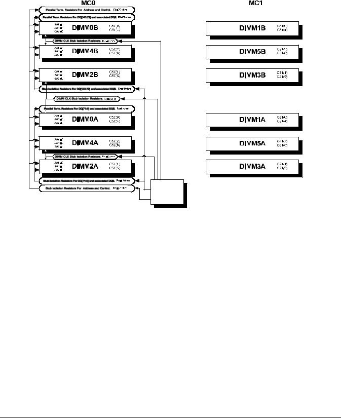
Overview
Detailed Server Description
Figure 1-6 shows the memory block diagram.
Figure 1-6 Memory Block Diagram
Memory |
Controller |
Memory Architecture
The I/O ASIC memory interface supports two DDR cells, each of which is 144 data bits wide. The memory subsystem physical design uses a comb-filter termination scheme for both the data and address/control buses. This part of the topology is similar to other DDR designs in the computer industry. Clocks are distributed directly from the I/O ASIC; each clock pair drives two DIMMs.
Memory data is protected by ECC. Eight ECC bits per DIMM protect 64 bits of data. The use of ECC enables correction of single-bit errors, and detection of multi-bit errors. Only DIMMs with ECC are qualified or supported.
DIMMs
The memory subsystem only supports DDR SDRAM (Double Data Rate Synchronous Dynamic Random Access Memory) technology utilizing industry-standard PC-1600 type DDR SDRAM DIMMs, 1.2" tall. This is currently being used by high-volume products. The DIMMs use a 184-pin JEDEC standard connector.
DIMMs are loaded in groups of four, known as a rank or quad (except for 256 MB DIMMs, which is loaded in pairs). All four DIMMs in a rank or quad must be the same size. The following information summarizes the memory solutions.
28 |
Chapter 1 |

Overview
Detailed Server Description
Memory Array Capacities
Table 1-2 lists the memory array capacities for the server.
Table 1-2 |
Memory Array Capacities |
||
|
|
|
|
Minimum and |
|
|
|
Maximum |
|
Single DIMM Size |
DDR SDRAM Count, Type and Technology |
Memory Size |
|
|
|
|
|
|
|
0.5 GB / 3 GB |
|
256 MB DIMM |
18 x 32 MB x 4 DDR SDRAMs (128 MB) |
|
|
|
|
2 GB / 6 GB |
|
512 MB DIMM |
36 x 32 MB x 4 DDR SDRAMs (128 MB) |
|
|
|
|
4 GB / 12 GB |
|
1024 MB DIMM |
36 x 64 MB x 4 DDR SDRAMs (256 MB) |
|
|
|
|
8 GB / 24 GB |
|
2048 MB DIMM |
36 x 128 MB x 4 DDR SDRAMs (512 MB) |
|
|
|
|
16 GB / 32 GB |
|
4096 MB DIMM |
36 x 256 MB x 4 DDR SDRAMs (1024 MB) |
|
|
|
|
Chip Spare Functionality
Chip spare enables an entire DDR SDRAM chip on a DIMM to be bypassed in the event that a multi-bit error is detected on the DDR SDRAM. In order to use the chip spare functionality on the server, only DIMMs built with ×4 DDR SDRAM parts are used, and these DIMMs must be loaded in quads.
The memory subsystem design supports the I/O ASIC chip’s spare functionality. Chip spare enables an entire SDRAM chip on a DIMM to be bypassed/replaced in the event that a multi-bit error is detected on that SDRAM. In order to use the chip spare functionality, only DIMMs built with x4 SDRAM parts are used, and these DIMMs must be loaded in quads (2 DIMMs per memory cell, loaded in the same location in each memory cell). Each DIMM within a quad must be identical to all the other DIMMs in the quad.
Using the DIMM loading order figure from above, chip spare is achieved if four identical DIMMs are loaded in the slots labeled “1st” and “2nd.” If more DIMMs are added, they must be loaded in quads in order to maintain the chip spare functionality. If more DIMMs are added to the example case, four identical DIMMs (identical to each other, but can be different from the original quad that was loaded) must be loaded in the slots labeled “3rd” and “4th.”
Maximum memory capability of the HP 9000 rp3440 server is 24 GB or 32 GB. If 4 GB DIMMs are used, install eight DIMMs in the first eight slots. The remaining slots (9-12) must remain empty when 4 GB DIMMs are used.
Serial Presence Detect
Each DIMM contains an I2C EEPROM whose content describes the module’s characteristics: speed, technology, revision, vendor, etc. This feature is called serial presence detect (SPD). Firmware typically uses this information to detect unmatched pairs of DIMMs, and configure certain memory subsystem parameters.
The SPD information for DIMMs loaded in the system are also accessible to the BMC through the I2C bus.
I/O Bus Interface
The I/O bus interface has these features:
•Provides industry standard PCI 33 MHz and 66 MHz, PCI-X 66 MHz to 133 MHz, 32 or 64 data bit support.
•Uses 3.3V PCI only, and it does not support 5V PCI.
•Optimizes for DMA performance.
Chapter 1 |
29 |

Overview
Detailed Server Description
•Supports 3.3V or universal-keyed PCI cards. 5V-keyed PCI cards are not supported.
Processor Dependent Hardware (PDH) Controller
The Processor Dependent Hardware (PDH) controller provides the following features.
•16-bit PDH bus with reserved address space for the following:
—Flash memory
—Nonvolatile memory
—Scratch RAM
—Real time clock
—UARTs
—External registers
—Firmware read/writable registers
—Two general purpose 32-bit registers
—Semaphore registers
—Monarch selection registers
—Test and reset register
•Reset and INIT generation
Field Programmable Gate Array
The Field Programmable Gate array (FPGA) provides ACPI and LPC support for the PDH bus and provides these features:
•ACPI 2.0 interface.
•LPC bus interface to support BMC.
•Decoding logic for PDH devices.
BMC
The BMC supports the industry-standard Intelligent Platform Management Interface (IPMI) specification. This specification describes the management features that have been built into the system board. These features include: diagnostics (both local and remote), console support, configuration management, hardware management and troubleshooting.
The BMC provides the following:
•Compliance with IPMI 1.0.
•Tachometer inputs for fan speed monitoring.
•Pulse width modulator outputs for fan speed control.
•Push-button inputs for front panel buttons and switches.
•One serial port, multiplexed with the system console port.
•Remote access and intelligent chassis management bus (ICMB) support.
•Three I2C master/slave ports (one of the ports is used for intelligent platform management bus (IPMB).
30 |
Chapter 1 |
Loading...