


 Loading...
HP 1820 Switches
Management and Configuration Guide

HP 1820 Switches
October 2016
Management and Configuration Guide

© Copyright 2015, 2016 Hewlett Packard Enterprise Development, L.P. The information contained herein is subject to change without notice. All Rights Reserved.
This document contains proprietary information, which is protected by copyright. No part of this document may be photocopied, reproduced, or translated into another language without the prior written consent of HewlettPackard.
Publication Number
5998-7651a October 2016
Applicable Products
HP 1820-8G Switch |
J9979A |
HP 1820-8G-PoE+ Switch |
J9982A |
HP 1820-24G Switch |
J9980A |
HP 1820-24G-PoE+ Switch |
J9983A |
HP 1820-48G Switch |
J9981A |
HP 1820-48G-PoE+ Switch |
J9984A |
Trademark Credits
Microsoft®, Windows®, and Windows NT® are US registered trademarks of Microsoft Corporation. JavaTM is a US trademark of Sun Microsystems, Inc.
Open Source Code Notice
Open Source Software shall mean those portions of the software that were made available to HP pursuant to, and may only be distributed pursuant to, the GNU General Public License* or a similar license that prohibits distribution of Open Source Software or derivative works of the Open Source Software on alternative terms.
HP makes such Open Source Software available to you pursuant to the same terms on which such Open Source Software was made available to HP and on no other or additional terms.
The Open Source Software modules and “make” files contained in the Software are available for HP in the form of a compact disk (CD). The CD includes the “original package” (original source files plus the “make” files) as well as a “patch” file that accounts for the modification made from the original source code. To receive the CD, HP charges a small fee in order to cover the actual costs of manufacturing and shipping the CD.
The information contained herein is subject to change without notice.
Disclaimer
The information contained herein is subject to change without notice. The only warranties for Hewlett Packard Enterprise products and services are set forth in the express warranty statements accompanying such products and services.
Nothing herein should be construed as constituting an additional warranty. Hewlett Packard Enterprise shall not be liable for technical or editorial errors or omissions contained herein.
Confidential computer software. Valid license from Hewlett Packard Enterprise required for possession, use, or copying. Consistent with FAR 12.211 and 12.212, Commercial Computer Software, Computer Software Documentation, and Technical Data for Commercial Items are licensed to the U.S. Government under vendor's standard commercial license.
Warranty
For HPE networking warranty information, visit www.hpe.com/networking/warranty
A copy of the specific warranty terms applicable to your Hewlett Packard Enterprise products and replacement parts can be obtained from your HPE Sales and Service Office or authorized dealer.
Hewlett Packard Enterprise
8000 Foothills Boulevard, m/s 5551 Roseville, California 95747-5551 www.hpe.com/networking/support

Preface
Preface
About This Document
HP 1820 series switches provide reliable, plug-and-play Gigabit network connectivity. As the follow-on to the popular HP Switch 1810 series, the HP 1820 series switches provide extended power-over-Ethernet capabilities, support additional networking protocols such as LLDP-MED and IGMP snooping, and provide enhanced switch management capabilities. The HP 1820 series switches are ideal for open offices that require silent operation or businesses making the transition from unmanaged to managed networks.
The HP 1820 series switches can be managed in-band from a remote network station using a web-based graphical user interface (GUI), and its configuration may also be viewed using the SNMP manager. This guide describes how to configure and view the software features using the web GUI.
Audience
The information in this guide is primarily intended for system administrators and support providers who are responsible for configuring, operating, or supporting a network using HP 1820 series switch software. An understanding of the software specifications for the networking device platform, and a basic knowledge of Ethernet and networking concepts, are presumed.
About Your Switch Manual Set
The switch manual set includes the following:
■Quick Setup Guide - a printed guide shipped with your switch. Provides illustrations for basic installation and setup guidelines.
■Regulatory and Safety Information- printed documentation shipped with your switch. Includes Regulatory statements and standards supported by the switch, along with product specifications.
■Installation and Getting Started Guide - (HP web site only). Provides detailed installation guide for your switch, including physical installation on your network, basic troubleshooting, product specifications, supported accessories, Regulatory and Safety information.
■Management and Configuration Guide - This guide describes how to manage and configure switch features using a web browser interface.
■Release Notes - (HP web site only). Provides information on software updates. The Release Notes describe new features, fixes, and enhancements that become available between revisions of the above guides.
iii

Preface
Note
For the latest version of all HPE documentation, visit the HPE web site at www.hpe.com/networking/ support. Then select your switch product.
Supported Features
HP 1820 series switches include support for the following features:
Feature |
1820 Series Switches |
|
|
HTTP and HTTPS sessions |
4 each, 8 total |
SNMP v1/v2c (read-only) community |
1 |
MAC table |
8000 entries for 8- and 24-port |
|
switches; 16000 entries for 48-port |
|
switches |
SNTP server configuration |
1 |
|
|
Time zones count |
91 |
Jumbo frame size |
9216 bytes |
Soft session web session timeout |
1 min–60 min |
Hard session web session timeout |
1 Hr–168 Hrs |
|
|
Trunk configuration (1820-8G/1820-8G- |
4 |
PoE+) |
|
Trunk configuration (1820-24G/1820-24G- |
8 |
PoE+) |
|
Trunk configuration (1820-48G) |
16 |
Trunk membership ports (1820-8G/1820-8G- |
4 |
PoE+/1820-24G/1820-24G-PoE+) |
|
Trunk membership ports (1820-48G) |
8 |
|
|
VLANs |
64 |
VLAN IDs |
1-4093 |
VLAN priority levels |
0–7 |
Syslog servers |
1 |
|
|
Buffered logs |
100 (total storage 10K) |
Maintenance users |
1 |
Password length |
8 chars–64 chars |
Images |
2 |
|
|
iv

Contents
Preface
About This Document . . . . . . . . . . . . . . . . . . . . . . . . . . . . . . . . . . . . . . . . . . . . . . . . . . . . . . . . . . . . . . . . . iii About Your Switch Manual Set . . . . . . . . . . . . . . . . . . . . . . . . . . . . . . . . . . . . . . . . . . . . . . . . . . . . . . . . . iii Supported Features . . . . . . . . . . . . . . . . . . . . . . . . . . . . . . . . . . . . . . . . . . . . . . . . . . . . . . . . . . . . . . . . . . . .iv
1 Getting Started
Connecting the Switch to a Network . . . . . . . . . . . . . . . . . . . . . . . . . . . . . . . . . . . . . . . . . . . . . . . . . . . 1-1 Operating System and Browser Support . . . . . . . . . . . . . . . . . . . . . . . . . . . . . . . . . . . . . . . . . . . . . 1-2 Getting Started With the Web Interface . . . . . . . . . . . . . . . . . . . . . . . . . . . . . . . . . . . . . . . . . . . . . . . . . 1-3 Logging On . . . . . . . . . . . . . . . . . . . . . . . . . . . . . . . . . . . . . . . . . . . . . . . . . . . . . . . . . . . . . . . . . . . . . . 1-3 Interface Layout and Features . . . . . . . . . . . . . . . . . . . . . . . . . . . . . . . . . . . . . . . . . . . . . . . . . . . . . 1-4 Common Page Elements . . . . . . . . . . . . . . . . . . . . . . . . . . . . . . . . . . . . . . . . . . . . . . . . . . . . . . . . . . 1-5 Saving Changes . . . . . . . . . . . . . . . . . . . . . . . . . . . . . . . . . . . . . . . . . . . . . . . . . . . . . . . . . . . . . . . . . . 1-5 Graphical Switch . . . . . . . . . . . . . . . . . . . . . . . . . . . . . . . . . . . . . . . . . . . . . . . . . . . . . . . . . . . . . . . . 1-5
2Dashboard
3Setup Network
Get Connected . . . . . . . . . . . . . . . . . . . . . . . . . . . . . . . . . . . . . . . . . . . . . . . . . . . . . . . . . . . . . . . . . . . . . . 3-1
System Time Pages . . . . . . . . . . . . . . . . . . . . . . . . . . . . . . . . . . . . . . . . . . . . . . . . . . . . . . . . . . . . . . . . . . 3-4
Time Zone Summary . . . . . . . . . . . . . . . . . . . . . . . . . . . . . . . . . . . . . . . . . . . . . . . . . . . . . . . . . . . . . 3-4
Time Configuration . . . . . . . . . . . . . . . . . . . . . . . . . . . . . . . . . . . . . . . . . . . . . . . . . . . . . . . . . . . . . . 3-6
Time Zone Configuration . . . . . . . . . . . . . . . . . . . . . . . . . . . . . . . . . . . . . . . . . . . . . . . . . . . . . . . . . . 3-8
Daylight Saving Time Configuration . . . . . . . . . . . . . . . . . . . . . . . . . . . . . . . . . . . . . . . . . . . . . . . . 3-9
4 Switching Features
Port Configuration . . . . . . . . . . . . . . . . . . . . . . . . . . . . . . . . . . . . . . . . . . . . . . . . . . . . . . . . . . . . . . . . . . . 4-1
Port Status . . . . . . . . . . . . . . . . . . . . . . . . . . . . . . . . . . . . . . . . . . . . . . . . . . . . . . . . . . . . . . . . . . . . . . 4-1
Port Summary Statistics . . . . . . . . . . . . . . . . . . . . . . . . . . . . . . . . . . . . . . . . . . . . . . . . . . . . . . . . . . 4-3
Port Mirroring . . . . . . . . . . . . . . . . . . . . . . . . . . . . . . . . . . . . . . . . . . . . . . . . . . . . . . . . . . . . . . . . . . . . . . 4-5
Jumbo Frames . . . . . . . . . . . . . . . . . . . . . . . . . . . . . . . . . . . . . . . . . . . . . . . . . . . . . . . . . . . . . . . . . . . . . . 4-7
Flow Control . . . . . . . . . . . . . . . . . . . . . . . . . . . . . . . . . . . . . . . . . . . . . . . . . . . . . . . . . . . . . . . . . . . . . . . 4-8
Spanning Tree . . . . . . . . . . . . . . . . . . . . . . . . . . . . . . . . . . . . . . . . . . . . . . . . . . . . . . . . . . . . . . . . . . . . . . 4-9
Global STP Settings and Port Status . . . . . . . . . . . . . . . . . . . . . . . . . . . . . . . . . . . . . . . . . . . . . . . 4-10
Port STP Settings . . . . . . . . . . . . . . . . . . . . . . . . . . . . . . . . . . . . . . . . . . . . . . . . . . . . . . . . . . . . . . . 4-13
Loop Protection . . . . . . . . . . . . . . . . . . . . . . . . . . . . . . . . . . . . . . . . . . . . . . . . . . . . . . . . . . . . . . . . . . . . 4-16
Loop Protection Status . . . . . . . . . . . . . . . . . . . . . . . . . . . . . . . . . . . . . . . . . . . . . . . . . . . . . . . . . . 4-16
Loop Protection Configuration . . . . . . . . . . . . . . . . . . . . . . . . . . . . . . . . . . . . . . . . . . . . . . . . . . . . 4-17
IGMP Snooping . . . . . . . . . . . . . . . . . . . . . . . . . . . . . . . . . . . . . . . . . . . . . . . . . . . . . . . . . . . . . . . . . . . . 4-20
v

5 Virtual LAN
Viewing VLAN Status and Adding VLANs . . . . . . . . . . . . . . . . . . . . . . . . . . . . . . . . . . . . . . . . . . . . . . . . 5-1
Adding VLANs . . . . . . . . . . . . . . . . . . . . . . . . . . . . . . . . . . . . . . . . . . . . . . . . . . . . . . . . . . . . . . . . . . . 5-2
Changing a VLAN Name . . . . . . . . . . . . . . . . . . . . . . . . . . . . . . . . . . . . . . . . . . . . . . . . . . . . . . . . . . . 5-2
Configuring Interfaces as VLAN Members . . . . . . . . . . . . . . . . . . . . . . . . . . . . . . . . . . . . . . . . . . . . . . . 5-3
VLAN Port Configuration . . . . . . . . . . . . . . . . . . . . . . . . . . . . . . . . . . . . . . . . . . . . . . . . . . . . . . . . . . . . . 5-4
6 Trunks
Trunk Configuration . . . . . . . . . . . . . . . . . . . . . . . . . . . . . . . . . . . . . . . . . . . . . . . . . . . . . . . . . . . . . . . . . 6-1
Modifying Trunk Settings . . . . . . . . . . . . . . . . . . . . . . . . . . . . . . . . . . . . . . . . . . . . . . . . . . . . . . . . . 6-2
Trunk Statistics . . . . . . . . . . . . . . . . . . . . . . . . . . . . . . . . . . . . . . . . . . . . . . . . . . . . . . . . . . . . . . . . . . . . . 6-4
7 Link Layer Discovery Protocol (LLDP and LLDP-MED)
LLDP Global Configuration . . . . . . . . . . . . . . . . . . . . . . . . . . . . . . . . . . . . . . . . . . . . . . . . . . . . . . . . . . . 7-1
LLDP Local Device Summary . . . . . . . . . . . . . . . . . . . . . . . . . . . . . . . . . . . . . . . . . . . . . . . . . . . . . . . . . . 7-4
Displaying Port Details . . . . . . . . . . . . . . . . . . . . . . . . . . . . . . . . . . . . . . . . . . . . . . . . . . . . . . . . . . . 7-5
LLDP Remote Device Summary . . . . . . . . . . . . . . . . . . . . . . . . . . . . . . . . . . . . . . . . . . . . . . . . . . . . . . . . 7-6
LLDP Global Statistics . . . . . . . . . . . . . . . . . . . . . . . . . . . . . . . . . . . . . . . . . . . . . . . . . . . . . . . . . . . . . . . 7-7
LLDP-MED Global Configuration . . . . . . . . . . . . . . . . . . . . . . . . . . . . . . . . . . . . . . . . . . . . . . . . . . . . . . 7-9
LLDP-MED Local Device Summary . . . . . . . . . . . . . . . . . . . . . . . . . . . . . . . . . . . . . . . . . . . . . . . . . . . . 7-11
LLDP-MED Remote Device Summary . . . . . . . . . . . . . . . . . . . . . . . . . . . . . . . . . . . . . . . . . . . . . . . . . . 7-12
Displaying Remote Device Details . . . . . . . . . . . . . . . . . . . . . . . . . . . . . . . . . . . . . . . . . . . . . . . . . 7-12
8 Power Over Ethernet
PoE Capabilities . . . . . . . . . . . . . . . . . . . . . . . . . . . . . . . . . . . . . . . . . . . . . . . . . . . . . . . . . . . . . . . . . . . . . 8-1
PoE Configuration . . . . . . . . . . . . . . . . . . . . . . . . . . . . . . . . . . . . . . . . . . . . . . . . . . . . . . . . . . . . . . . . . . . 8-2
PoE Port Configuration . . . . . . . . . . . . . . . . . . . . . . . . . . . . . . . . . . . . . . . . . . . . . . . . . . . . . . . . . . . . . . |
8-3 |
Modifying Port PoE Settings . . . . . . . . . . . . . . . . . . . . . . . . . . . . . . . . . . . . . . . . . . . . . . . . . . . . . . . |
8-4 |
Viewing PoE Port Details . . . . . . . . . . . . . . . . . . . . . . . . . . . . . . . . . . . . . . . . . . . . . . . . . . . . . . . . . |
8-5 |
PoE Port Schedule . . . . . . . . . . . . . . . . . . . . . . . . . . . . . . . . . . . . . . . . . . . . . . . . . . . . . . . . . . . . . . . . . . . 8-6
Configuring an Absolute Time Period . . . . . . . . . . . . . . . . . . . . . . . . . . . . . . . . . . . . . . . . . . . . . . . 8-7
Adding a Periodic Time Period . . . . . . . . . . . . . . . . . . . . . . . . . . . . . . . . . . . . . . . . . . . . . . . . . . . . . 8-8
9 Security
Advanced Security Configuration . . . . . . . . . . . . . . . . . . . . . . . . . . . . . . . . . . . . . . . . . . . . . . . . . . . . . . 9-1
Secure Connection . . . . . . . . . . . . . . . . . . . . . . . . . . . . . . . . . . . . . . . . . . . . . . . . . . . . . . . . . . . . . . . . . . 9-3
Uploading SSL Certificates and Encryption Files . . . . . . . . . . . . . . . . . . . . . . . . . . . . . . . . . . . . . 9-5
10 Green Features
Green Features Configuration . . . . . . . . . . . . . . . . . . . . . . . . . . . . . . . . . . . . . . . . . . . . . . . . . . . . . . . . 10-1
EEE Status . . . . . . . . . . . . . . . . . . . . . . . . . . . . . . . . . . . . . . . . . . . . . . . . . . . . . . . . . . . . . . . . . . . . . . . . 10-3
vi

11 Diagnostics
Buffered Log . . . . . . . . . . . . . . . . . . . . . . . . . . . . . . . . . . . . . . . . . . . . . . . . . . . . . . . . . . . . . . . . . . . . . . . 11-1
Log Configuration . . . . . . . . . . . . . . . . . . . . . . . . . . . . . . . . . . . . . . . . . . . . . . . . . . . . . . . . . . . . . . . . . . 11-3
Ping Test . . . . . . . . . . . . . . . . . . . . . . . . . . . . . . . . . . . . . . . . . . . . . . . . . . . . . . . . . . . . . . . . . . . . . . . . . . 11-5
Reboot Switch . . . . . . . . . . . . . . . . . . . . . . . . . . . . . . . . . . . . . . . . . . . . . . . . . . . . . . . . . . . . . . . . . . . . . 11-6
Factory Defaults . . . . . . . . . . . . . . . . . . . . . . . . . . . . . . . . . . . . . . . . . . . . . . . . . . . . . . . . . . . . . . . . . . . 11-6
Support File . . . . . . . . . . . . . . . . . . . . . . . . . . . . . . . . . . . . . . . . . . . . . . . . . . . . . . . . . . . . . . . . . . . . . . . 11-7
Locator . . . . . . . . . . . . . . . . . . . . . . . . . . . . . . . . . . . . . . . . . . . . . . . . . . . . . . . . . . . . . . . . . . . . . . . . . . . 11-8
MAC Table . . . . . . . . . . . . . . . . . . . . . . . . . . . . . . . . . . . . . . . . . . . . . . . . . . . . . . . . . . . . . . . . . . . . . . . . 11-9
12 Maintenance Pages
Password Manager . . . . . . . . . . . . . . . . . . . . . . . . . . . . . . . . . . . . . . . . . . . . . . . . . . . . . . . . . . . . . . . . . |
12-1 |
Backup and Update Manager . . . . . . . . . . . . . . . . . . . . . . . . . . . . . . . . . . . . . . . . . . . . . . . . . . . . . . . . . |
12-2 |
Backing Up Files . . . . . . . . . . . . . . . . . . . . . . . . . . . . . . . . . . . . . . . . . . . . . . . . . . . . . . . . . . . . . . . . |
12-2 |
Updating Files . . . . . . . . . . . . . . . . . . . . . . . . . . . . . . . . . . . . . . . . . . . . . . . . . . . . . . . . . . . . . . . . . . |
12-3 |
Dual Image Configuration . . . . . . . . . . . . . . . . . . . . . . . . . . . . . . . . . . . . . . . . . . . . . . . . . . . . . . . . . . . |
12-5 |
vii

viii
1
Getting Started
Note
This chapter describes how to make the initial connections to the switch and provides an overview of the web interface.
Connecting the Switch to a Network
To enable remote management of the switch through a web browser, the switch must be connected to the network. The switch is preconfigured with an IP address for management purposes. After initial configuration, the switch can also be configured to acquire its address from a DHCP server on the network.
By default, the switch is assigned the following static IP information for access to the web interface:
■ |
IP address: |
192.168.1.1 |
■ |
Network mask: |
255.255.255.0 |
■Gateway: 0.0.0.0
1.Connect the switch to the management PC or to the network using any of the available network ports.
2.Power on the switch.
3.Set the IP address of the management PC’s network adaptor to be in the same subnet as the switch.
Example: Set it to IP address 192.168.1.2, mask 255.255.255.0.
4.Enter the IP address shown above in the web browser. See page 1-3 for web browser requirements.
Thereafter, use the web interface to configure a different IP address or configure the switch as a DHCP client so that it receives a dynamically assigned IP address from the network.
■If you enable DHCP for IP network configuration, the switch must be connected to the same network as the DHCP server. You will need to access your DHCP server to determine the IP address assigned to the switch.
■The switch supports LLDP (Link Layer Discovery Protocol), allowing discovery of its IP address from a connected device or management station.
■If DHCP is used for configuration and the switch fails to be configured, the IP address 192.168.1.1 is assigned to the switch interface.
After the switch is able to communicate on your network, enter its IP address into your web browser’s address field to access the switch management features.
1-1

Getting Started
Connecting the Switch to a Network
Operating System and Browser Support
The following operating systems and browsers with JavaScript enabled are supported:
Operating System |
Browser |
|
|
Windows 7 |
Internet Explorer 9, 10 |
|
Firefox 25 |
|
Chrome 30 |
Windows 8 |
Internet Explorer 10 |
|
Firefox 25 |
|
Chrome 30 |
MacOS X 10.9 |
Firefox 25 |
|
Chrome 30 |
|
Safari 7 |
|
|
1-2
Getting Started
Getting Started With the Web Interface
Getting Started With the Web Interface
This section describes the following web pages:
■“Logging On” on page 1-3
■“Interface Layout and Features” on page 1-4
Logging On
Follow these steps to log on through the web interface:
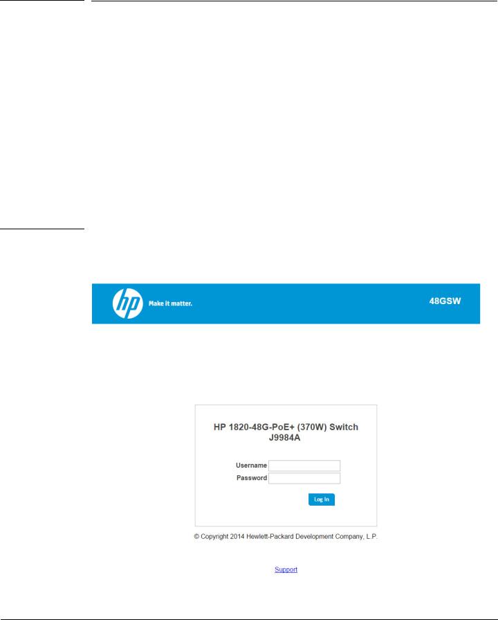
1.Open a web browser and enter the IP address of the switch in the web browser address field.
2.On the Login page, enter the username and password (if one has been set), and then click Log In.
By default, the username is admin and there is no password. After the initial log on, the administrator may configure a password.
Note |
To set the password or change the username, see “Password Manager” on page 12-1. |
|
Figure 1-1. Login Page |
|
1-3

Getting Started
Getting Started With the Web Interface
Interface Layout and Features
Figure 1-2 shows the initial view.
Figure 1-2. Interface Layout and Features
Navigation Pane |
|
Graphical Switch |
|
Common Links |
|
|
|
|
|
Click on any topic in the navigation page to display related configuration options.
The Dashboard page displays when you first log on and when you click Dashboard in the navigation pane. See “Dashboard” on page 2-1 for more information.
You can click the Setup Network link beneath Dashboard to display the Get Connected page, which you use to set up a management connection to the switch. See “Get Connected” on page 3-1 for more information.
The graphical switch displays summary information for the switch LEDs and port status. For information on this feature see “Graphical Switch” on page 1-5.
1-4
Getting Started
Getting Started With the Web Interface
Common Page Elements
■Click on any page to display a help panel that explains the fields and configuration options on the page.
■Click  to send the updated configuration to the switch. Applied changes update the device running configuration and take effect immediately. If you want the device to retain these changes across a reboot, you must first save the configuration. See “Saving Changes” on page 1-5.
■Click  to refresh the page with the latest information from the switch.
■Click  to clear any configurations changes that have not yet been applied on a page.
■Click  to end the current management session.
Saving Changes
When you click  , changes are saved to the running configuration file in RAM. Unless you save them to system flash memory, the changes will be lost if the system reboots. To save them permanently, click
on the upper right side of the page. Note that when there are unsaved changes, the button displays a file image ( ). A page displays to confirm that you want to save, followed by a page that confirms that the operation was completed successfully.
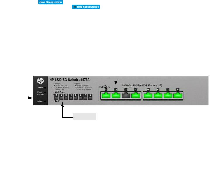
Graphical Switch
The graphical switch, shown in Figure 1-3, displays at the top of the page as a representation of the physical switch to provide status information about individual ports. The graphical switch enables easy system configuration and web-based navigation.
You can right-click anywhere on the graphic and select from the menu to display the product information on the Dashboard page, to refresh the graphic display, and to set the automatic refresh rate.
Figure 1-3. Graphical Switch
|
|
|
|
Port Configuration and Summary |
||
System LEDs |
||||||
|
(Point, left-click, or right-click on any port for options) |
|||||
|
|
|
|
|
|
|
|
|
|
|
|
|
|
|
|
|
|
|
|
|
Port LEDs
Port Configuration and Summary
You can point to any port to display the following information about the port:
■The link status (up or down).
■Auto negotiation status.
■Speed and full-duplex/half-duplex settings.
1-5

Getting Started
Getting Started With the Web Interface
■The maximum transmission unit (MTU), which is the largest packet size that can be transmitted on the port.
You can left-click a port to display the Port Status page.
System LEDs
The following System LEDs reflect the status of the actual LEDs on the switch:
■Power (Green)
•On— The switch is receiving power.
•Blinking—The switch is receiving power through its Power Over Ethernet (PoE) port.
•Off—The switch is NOT receiving power.
■Fault/Locator (Orange)
•Blinking rapidly—A fault has occurred, other than during self-test.
•Blinking slowly—The locator function has been enabled to help physically locate the switch.
•On—If continuously on, no firmware was detected upon boot-up.
•Off—The locator function is disabled and the switch is operating properly.
Port LEDs
Each 10/100/1000 Mbps RJ45 port has two single-color LEDs that reflect the status of the actual LEDs on the switch. The upper LED indicates the link/activity status and the lower LED indicates the mode (speed).
The Link/Act LED status can be one of the following:
■On—A self-test is being performed on the port.
■Blinking—The port has network activity.
■Off—The port has no active network cable connected, is not receiving link signal, or is disabled. The function of the Mode LED changes depending on whether the switch supports Power-Over-Ethernet:
■When the switch supports PoE, the Mode LED indicates PoE status for port:
•On—PoE mode is enabled on the port.
•Blinking—The PoE port failed or is not currently providing power because it has temporarily exceeded its allocated power limit.
•Off—PoE mode is disabled on the port.
■When the switch does not support PoE, the Mode LED indicates port speed:
•On—The port is operating continuously at 1000 Mbps.
•Blinking—The port is operating at 100 Mbps.
•Off—The port is operating at 10 Mbps.
1-6
2
Dashboard
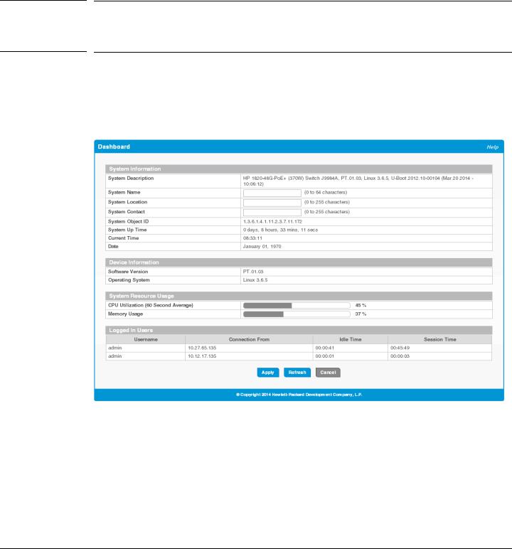
You can use the Dashboard page to display and configure basic information about the system.
The Dashboard page displays basic information such as the configurable switch name and description, the IP address for management access, and the software and operating system versions. This page also shows resource usage statistics.
This page is displayed when you first log on or when you click Dashboard in the navigation pane.
Figure 2-1. Dashboard Page
If you update the name, location, or contact information, click Apply to save any changes for the current boot session. The changes take effect immediately.
2-1

Dashboard
Table 2-1. Dashboard Page Fields
Field |
Description |
|
|
System Information |
|
|
|
System Description |
A description of the switch hardware, including the hardware type, software version, |
|
operating system version, and boot loader (U-Boot) version. |
|
|
System Name |
Enter the preferred name to identify this switch. A maximum of 64 alpha-numeric characters |
|
including hyphens, commas and spaces are allowed. This field is blank by default. |
|
The user configurable switch name will appear in the login screen banner. |
|
|
System Location |
Enter the location of this switch. A maximum of 255 alpha-numeric characters including |
|
hyphens, commas, and spaces are allowed. This field is blank by default. |
|
|
System Contact |
Enter the name of the contact person for this switch. A maximum of 255 alpha-numeric |
|
characters including hyphens, commas, and spaces are allowed. This field is blank by default. |
|
|
System Object ID |
The base object ID for the switch's enterprise MIB. |
|
|
System Up Time |
The time in days, hours and minutes since the last switch reboot. |
|
|
Current Time |
The current time in hours, minutes, and seconds as configured (24or 12-hr AM/PM format) |
|
by the user. |
|
|
Date |
The current date in month, day, and year format. |
|
|
Device Information |
|
|
|
Software Version |
The version of the code running on the switch. |
|
|
Operating System |
The version of the operating system running on the switch. |
|
|
System Resource Usage |
|
|
|
CPU Utilization |
The percentage of CPU utilization for the entire system averaged over the past 60 seconds. |
|
|
Memory Usage |
The percentage of total system memory (RAM) currently in use. |
Logged In Users—These fields display only when more than one user is logged into the management utility.
Username |
The username of each logged in user. |
|
|
Connection From |
The IP address from which the user logged in. |
|
|
Idle Time |
The time that has elapsed since the last user activity. |
|
|
Session Time |
The amount of time the user session has been active. |
|
|
2-2
3
Setup Network
You can use the Setup Network pages to configure how a management computer connects to the switch and how the switch connects to a server to synchronize its time.
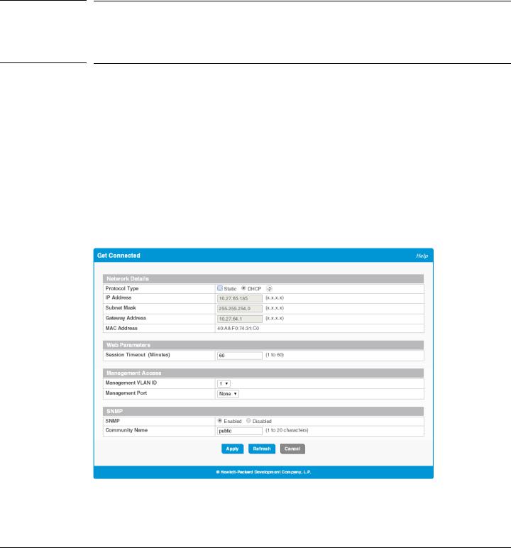
Get Connected
Use the Get Connected page to configure settings for the network interface. The network interface is defined by an IP address, subnet mask, and gateway. Any one of the switch's front-panel ports can be selected as the management port for the network interface. The configuration parameters associated with the switch's network interface do not affect the configuration of the front-panel ports through which traffic is switched or forwarded except that, for the management port, the port VLAN ID (PVID) will be the management VLAN.
To display the Get Connected page, click Setup Network > Get Connected.
In the example configuration in Figure 3-1, the switch is configured to acquire its IP address through DHCP, which is the default setting. Access to the management software is restricted to members of VLAN 1.
Figure 3-1. Get Connected Page
3-1

Setup Network
Get Connected
Table 3-1. Get Connected Fields
Field |
Description |
|
|
Network Details |
|
|
|
Protocol Type |
Select the type of network connection: |
|
• Static—Select this option to enable the IP address, subnet mask, and gateway fields for |
|
data entry. |
|
• DHCP—Select this option to enable the switch to obtain IP information from a DHCP |
|
server on the network. If the DHCP server responds, then the assigned IP address is used. |
|
If DHCP is enabled but the DHCP server does not respond, the default static IP address |
|
192.168.1.1 is used. DHCP operation is enabled by default. |
|
When a server assigns an IP address to the switch, it specifies the time for which the |
|
assignment is valid. After the time expires, the server may reclaim the address for |
|
assignment to another device. When DHCP is enabled, you can click to send a request |
|
to the DHCP server to renew the lease. |
|
Only a user-configured, static IP address is saved to flash. |
|
CAUTION: Changing the protocol type or IP address discontinues the current connection; |
|
you can log on again using the new IP information. |
|
|
IP Address |
The IPv4 address to be used. The default IP address is 192.168.1.1. |
|
Note: A broadcast IP address cannot be entered in this field. |
|
|
Subnet Mask |
The IPv4 subnet address to be used. The default IP subnet address is 255.255.255.0. |
|
|
Gateway Address |
The IPv4 gateway address to be used. When in doubt, set this to be the same as the default |
|
gateway address used by your PC. |
|
|
MAC Address |
The burned-in universally administered MAC address of this switch. |
|
|
Web Parameters |
|
|
|
Session Timeout |
Specify the amount of time in minutes that a connection to the web interface remains active, |
|
assuming no user activity. The range is 1 to 60 and the default is 5 minutes. To keep the |
|
connection active regardless of user activity, set this value to 0. |
|
CAUTION: When a session window is closed without logging out, the server connection |
|
remains open until the session times out. When the session timeout is set to 0, closing a |
|
session window without logging out keeps the session open at the server indefinitely. In such |
|
cases, you may fail to connect after the maximum sessions are left open indefinitely. |
|
|
Management Access |
|
|
|
Management VLAN |
Access to the management software is controlled by the assignment of a management VLAN |
ID |
ID. Only ports that are members of the management VLAN allow access to the management |
|
software. |
|
By default, the management VLAN ID is 1. The allowed range is 1 to 4093. All ports are |
|
members of VLAN 1 by default; the administrator may want to create a different VLAN to |
|
assign as the management VLAN and associate it with a management port (see the next field). |
|
A VLAN that does not have any member ports (either tagged or untagged) cannot be |
|
configured as the management VLAN. |
|
When the network protocol is configured to be DHCP, any change in the configured |
|
management VLAN ID may cause disruption in connectivity because the switch acquires a |
|
new IP address when the management subnet is changed. To reconnect to the switch, the user |
|
must determine the new IP address by viewing the log on the DHCP server. |
|
|
3-2
|
|
|
|
Setup Network |
|
|
|
|
Get Connected |
|
|
|
|
|
|
|
Field |
Description |
|
|
|
|
|
|
|
|
Management Port |
Access to the management software can also be controlled by the selection of a management |
|
|
|
|
port. The selected management port is auto-configured to be an untagged member of the |
|
|
|
|
management VLAN and is excluded from any other untagged VLANs. |
|
|
|
|
When the switch boots with the default configuration, any port can be used as management |
|
|
|
|
port and this field is configured as 'None'. |
|
|
|
|
You can configure a management port to ensure that a port always remains an untagged |
|
|
|
|
member of the configured management VLAN; this helps to ensure management connectivity |
|
|
|
|
in case of an accidental change in VLAN membership. |
|
|
|
|
If no management port is specified, then all ports that are members of the management VLAN |
|
|
|
|
provide access to the switch management interface. If a management port is configured, |
|
|
|
|
access to the switch is restricted to that port. For example, if VLAN 1 is the management |
|
|
|
|
VLAN and port 10 is the management port, other ports that are members of VLAN 1 will |
|
|
|
|
not provide access to the switch management interface. |
|
|
|
|
|
|
|
|
SNMP |
|
|
|
|
|
|
|
|
|
SNMP |
Enable or disable Simple Network Management Protocol (SNMP). If enabled, the |
|
|
|
|
administrator can view switch data using an SNMPv1/v2c manager. The switch supports |
|
|
|
|
read-only access to a limited set of MIBs. SNMP is enabled by default. |
|
|
|
|
|
|
|
|
Community Name |
Specify a community name or use the default name, public. |
|
|
|
|
The switch supports the following MIBs: |
|
|
|
|
• BRIDGE-MIB (IEEE 802.1Q) |
|
|
|
|
• LLDP-MIB (IEEE 802.3AB) |
|
|
|
|
• |
EtherLike-MIB |
|
|
|
• |
IF-MIB |
|
|
|
• |
RFC1213-MIB |
|
|
|
• RMON-MIB (RMON History as in v1) |
|
|
|
|
• Power Ethernet MIB (RFC3621), only on switches that support PoE+. (No SNMP |
|
|
|
|
|
information is available on configured PoE schedules.) |
|
|
|
||
|
|
Click Apply to save any changes for the current boot session. The changes take effect immediately. |
||
|
|
|
||
Note |
|
A power cycle does not reset the IP address to its factory-default value. If the configured IP address is unknown, |
||
|
|
you can perform a manual reset to factory defaults to regain access to the switch. |
||
|
|
|
|
|
3-3
Setup Network
System Time Pages
System Time Pages
You click Setup Network > System Time to display the web pages for configuring the system clock, SNTP client functionality, system time zone, and daylight saving time settings.
Time Zone Summary
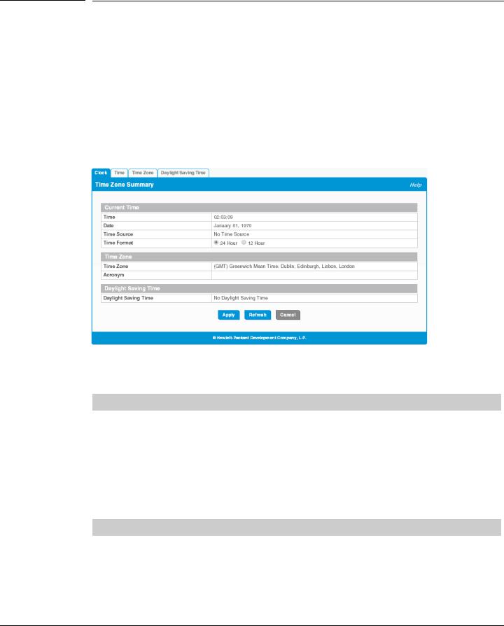
The Time Zone Summary page displays the current time, time zone, and Daylight Saving Time settings, and enables you to configure the time display format. To display the Time Zone Summary page, click Setup Network > System Time in the navigation bar and ensure that the Clock tab is selected.
Figure 3-2. Time Zone Summary Page
Table 3-2. Time Zone Summary Fields
Field |
Description |
|
|
Current Time |
|
|
|
Time |
The current time. This value is determined by an SNTP server. When SNTP is disabled, the |
|
system time increments from 00:00:00, 1 Jan 1970, which is set at bootup. |
|
|
Date |
The current date. |
|
|
Time Source |
The source from which the time and date is obtained: |
|
• SNTP—The time has been acquired from an SNTP server. |
|
• No Time Source—The time has been either manually configured or not configured at |
|
all. This is the default selection. |
|
|
Time Format |
Select 24 Hour (“military” time) or 12 Hour (the default) to specify the time display format. |
|
|
Time Zone |
|
|
|
Time Zone |
The currently set time zone. The default is (GMT) Greenwich Mean Time: Dublin, |
|
Edinburgh, Lisbon, London. |
|
|
Acronym |
The acronym for the time zone, if one is configured on the system (e.g., PST, EDT). |
|
|
3-4

Setup Network
System Time Pages
Field |
Description |
|
|
Daylight Saving Time |
|
Daylight Saving Time Shows whether Daylight Saving Time (DST) is enabled and the mode of operation:
•No Daylight Saving Time—No clock adjustment will be made for DST (default).
•Recurring Every Year—The settings will be in effect for the upcoming period and subsequent years.
•Non-Recurring—The settings will be in effect only for a specified period during the year (i.e., they will not carry forward to subsequent years).
If DST is enabled and the current time is within the configured DST period, then “(On DST)” displays following this field value.
For instructions on configuring the system time, see “Time Configuration” on page 3-6, “Time Zone Configuration” on page 3-8, and “Daylight Saving Time Configuration” on page 3-9.
3-5
Setup Network
System Time Pages
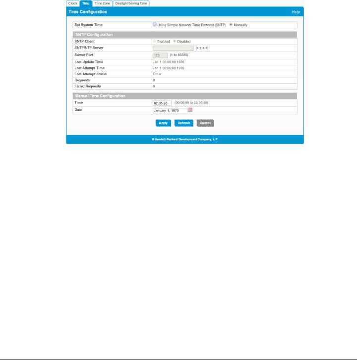
Time Configuration
You can configure the system time manually or acquire time information automatically from a Simple Network Time Protocol (SNTP) server. Using SNTP ensures accurate network device clock time synchronization up to the millisecond. Time synchronization is performed by a network SNTP server. The software operates only as an SNTP client and cannot provide time services to other systems.
To display the Time Configuration page, click Setup Network > System Time in the navigation pane and click the Time tab.
Figure 3-3. Time Configuration Page
3-6

Setup Network
System Time Pages
Table 3-3. Time Configuration Fields
Field |
Description |
|
|
Set System Time |
Select Using Simple Network Time Protocol (SNTP) to configure the switch to acquire its time |
|
settings from an SNTP server. When selected, only the SNTP Configuration fields are available |
|
for configuration. |
|
Select Manually to disable SNTP and configure the time manually. When selected, only the |
|
Manual Time Configuration fields are available for configuration. |
SNTP Configuration
SNTP Client |
Select Enabled or Disabled (default) to configure the SNTP client mode. When disabled, the |
|
system time increments from 00:00:00, 1 Jan 1970, which is set at bootup. |
|
|
SNTP/NTP Server |
Specify the IPv4 address of the SNTP server to send requests to. |
|
|
Server Port |
Specify the server's UDP port to listen for responses/broadcasts. The range is 1 to 65535 and the |
|
default is 123. |
|
|
Last Update Time |
The date and time (UTC) of the last update from this server. |
|
|
Last Attempt Time |
The data and time (UTC) that the switch last attempted to obtain the time from this server. |
Last Update Status The status of the last update request to the SNTP server, which can be one of the following values:
•Other—None of the following values apply or no message has been received.
•Success—The SNTP operation was successful and the system time was updated.
•Request Timed Out—A SNTP request timed out without receiving a response from the SNTP server.
•Bad Date Encoded—The time provided by the SNTP server is not valid.
•Version Not Supported—The SNTP protocol version supported by the server is not compatible with the version supported by the switch client.
•Server Unsynchronized—The SNTP server is not synchronized with its peers. This is indicated via the leap indicator field in the SNTP message.
•Blocked—The SNTP server indicated that no further requests were to be sent to this server. This is indicated by a stratum field equal to 0 in a message received from the server.
Requests |
The number of requests made to the SNTP sever since the switch was rebooted. |
|
|
Failed Requests |
The number of failed SNTP requests made to this server since last reboot. |
|
|
Manual Time Configuration |
|
|
|
Time |
Specify the current time in HH:MM:SS format. |
|
|
Date |
Click the date field to display a calendar and select the current date. |
|
|
Click Apply to save any changes for the current boot session. The changes take effect immediately.
3-7
Setup Network
System Time Pages
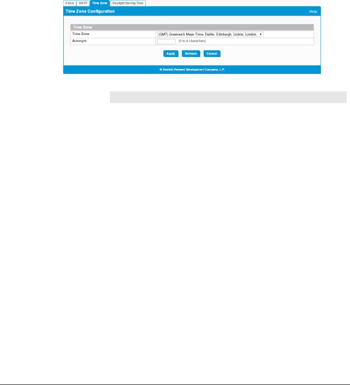
Time Zone Configuration
The Time Zone Configuration page is used to configure your local time zone.
To display this page, click Setup Network > System Time in the navigation pane and click the Time Zone tab.
Figure 3-4. Time Zone Configuration Page
Table 3-4. Time Zone Configuration Fields
Field |
Description |
|
|
Time Zone |
Select the time zone for your location. The default is (GMT) Greenwich Mean Time: Dublin, |
|
Edinburgh, Lisbon, London. |
|
|
Acronym |
Specify an acronym for the time zone. The acronym can have up to four alphanumeric characters |
|
and can contain dashes, underscores, and periods. |
|
|
Click Apply to save any the changes for the current boot session. The changes take effect immediately.
3-8

Setup Network
System Time Pages
Daylight Saving Time Configuration
The Daylight Saving Time Configuration page is used to configure if and when Daylight Saving Time (DST) occurs within your time zone. When configured, the system time adjusts automatically one hour forward at the start of the DST period, and one hour backward at the end.
To display the Daylight Saving Time page, click Setup Network > System Time in the navigation panel and click the Daylight Saving Time tab.
Figure 3-5. Daylight Saving Time Configuration Page
3-9

Setup Network
System Time Pages
Table 3-5. Daylight Saving Time Configuration Fields
Field |
Description |
|
|
Daylight Saving Time Select how DST will operate:
•Disable—No clock adjustment will be made for DST. This is the default selection.
•Recurring—The settings will be in effect for the upcoming period and subsequent years.
•EU—The system clock uses the standard recurring daylight saving time settings used in countries in the European Union.
•USA—The system clock uses the standard recurring daylight saving time settings used in the United States.
•Non-Recurring—The settings will be in effect only for a specified period during the year (that is, they will not carry forward to subsequent years).
When a DST mode is enabled, the clock will be adjusted one hour forward at the start of the
DST period and one hour backward at the end.
Date Range |
Set the following to indicate when the change to DST occurs and when it ends. |
|
These fields are editable when Non-Recurring is selected as the DST mode: |
|
• Start/End Date—Use the calendar to set the day, month, and year when the change to/ |
|
from DST occurs. Or, enter the hours and minutes in 24-hour format (HH:MM). |
|
• Starting Time of Day—Set the hour and minutes when the change to/from DST occurs. |
|
|
Recurring Date |
When Recurring is selected as the DST mode, the following fields display: |
|
• Start/End Week—Set the week of the month, from 1 to 5, when the change to/from DST |
|
occurs. The default is 1 (the first week of the month). |
|
• Start/End Day—Set the day of the week when the change to/from DST occurs. |
|
• Start/End Month—Set the month when the change to/from DST occurs. |
|
• Starting/Ending Time of Day—Set the hour and minutes when the change to/from DST |
|
occurs. |
|
|
Click Apply to save any the changes for the current boot session. The changes take effect immediately.
3-10
4
Switching Features
You can use the Switching pages to configure port operation and capabilities.
Port Configuration
You can use the Port Configuration pages to display port status, configure port settings, and view statistics on packets transmitted on the port.
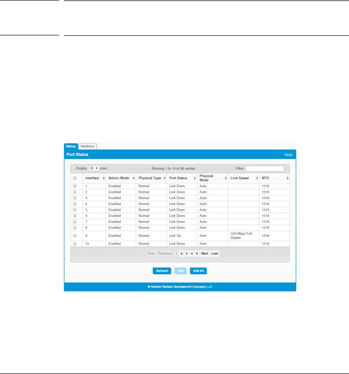
Port Status
The Port Status page displays the operational and administrative status of each port and enables port configuration. To view this page, click Switching > Port Configuration in the navigation pane.
Figure 4-1. Port Status Page
4-1
Switching Features
Port Configuration
Table 4-1. Port Status Fields
Field |
Description |
|
|
Interface |
The port or trunk ID. |
|
|
Admin Mode |
Displays whether the interface is administratively enabled or disabled. All ports are enabled by |
|
default. |
|
|
Physical Type |
The interface type, which can be one of the following: |
|
• Normal—The port is a normal port, which means it is not a LAG member or configured for |
|
port mirroring. All ports are normal ports by default. |
|
• Trunk Member—The port is a member of a trunk. |
|
• Mirrored—The port is configured to mirror its traffic (ingress, egress, or both) to another port |
|
(the probe port). |
|
• Probe—The port is configured to receive mirrored traffic from one or more source ports. |
|
|
Port Status |
The physical status (Link Up or Link Down) of the link at the port. |
|
|
Physical Mode |
Displays whether Auto negotiation is enabled or disabled on the port. |
|
If the mode is Auto, the port's maximum capability are advertised, and the duplex mode and speed |
|
are set from the auto-negotiation process. The physical mode for a trunk is “Trunk”. |
|
|
Link Speed |
The physical speed at which the port is operating. If no link is present, this field is empty. |
|
|
MTU |
The Maximum Transmission Unit (MTU) specifies the largest frame size that can be transmitted |
|
on the port. The default is 1518 bytes. |
|
|
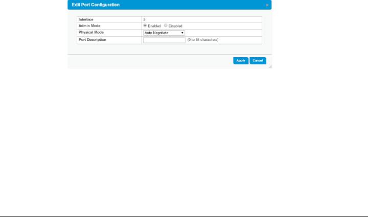
Modifying Interface Settings
To change the Admin Mode or Physical Mode of one or more interfaces, and to add a brief interface description, select the interfaces and click Edit. Or, click Edit All to modify all interfaces.
Figure 4-2. Edit Port Configuration Page
4-2
Loading...