


 Loading...
HP 1920-16G, 1920-24G, 1920-48G, 1920-8G, 1920-8G-PoE+ User Manual
...HP 1920 Gigabit Ethernet Switch Series
Getting Started Guide
5998-5626
Part number: 5998-5626
Document version: 6W101-20140820
Legal and notice information
© Copyright 2014 Hewlett-Packard Development Company, L.P.
No part of this documentation may be reproduced or transmitted in any form or by any means without prior written consent of Hewlett-Packard Development Company, L.P.
The information contained herein is subject to change without notice.
HEWLETT-PACKARD COMPANY MAKES NO WARRANTY OF ANY KIND WITH REGARD TO THIS MATERIAL, INCLUDING, BUT NOT LIMITED TO, THE IMPLIED WARRANTIES OF MERCHANTABILITY AND FITNESS FOR A PARTICULAR PURPOSE. Hewlett-Packard shall not be liable for errors contained herein or for incidental or consequential damages in connection with the furnishing, performance, or use of this material.
The only warranties for HP products and services are set forth in the express warranty statements accompanying such products and services. Nothing herein should be construed as constituting an additional warranty. HP shall not be liable for technical or editorial errors or omissions contained herein.

Contents
Preparing for installation ············································································································································· 1
Safety recommendations ··················································································································································1 Examining the installation site ·········································································································································2 Temperature/humidity ·············································································································································2 Cleanness··································································································································································2 EMI·············································································································································································3
Installing the switch ······················································································································································ 4
Mounting the switch in a 19-inch rack by using mounting brackets ···········································································4 Mounting the switch on a workbench·····························································································································7 Mounting the switch on a wall ········································································································································7 Connecting cables ····························································································································································9 Connecting network cable ······································································································································9 Installing the SFP transceiver module and optical fibers ······················································································9 Connecting the console cable······························································································································ 10 Connecting the AC power cord··························································································································· 10 Connecting the DC power cord··························································································································· 11 Verifying the installation················································································································································ 12
Accessing the switch for the first time·······················································································································13
Setting up the configuration environment···················································································································· 13 Connecting the console cable ······································································································································ 13 Console cable························································································································································ 13 Connection procedure ·········································································································································· 14 Setting terminal parameters ·········································································································································· 14 Powering on the switch·················································································································································· 17 Verification before power-on ······························································································································· 17 Powering on the switch········································································································································· 17
Support and other resources ·····································································································································19
Contacting HP ································································································································································ 19 Subscription service ·············································································································································· 19 Related information························································································································································ 19 Documents······························································································································································ 19 Websites································································································································································· 19 Conventions ···································································································································································· 20
Appendix A Chassis views and technical specifications ························································································22
Chassis views ································································································································································· 22 1920-8G ································································································································································ 22 1920-16G······························································································································································ 22 1920-24G······························································································································································ 23 1920-48G······························································································································································ 23 1920-8G-PoE+ (65W)·········································································································································· 24 1920-8G-PoE+ (180W) ······································································································································· 24 1920-24G-PoE+ (180W) ····································································································································· 25 1920-24G-PoE+ (370W) ····································································································································· 25
Physical specifications ··················································································································································· 26 Chassis dimensions and weights ························································································································· 26 Ports and interface card slots ······························································································································· 26 Environmental specifications········································································································································· 27
i
Power specifications ······················································································································································ 27 AC input voltage specifications ··························································································································· 27 RPS DC input voltage specifications and RPS compatibility ············································································· 27 Power consumption specifications for non-PoE switches··················································································· 27 Power consumption specifications for PoE switches ·························································································· 27
Cooling system ······························································································································································· 28
Appendix B LEDs························································································································································29
Power LED ······························································································································································ 29 Copper port LEDs ·················································································································································· 29 Fiber port LEDs······················································································································································· 29 RPS LED··································································································································································· 30
Appendix C Troubleshooting ····································································································································31
ii

Preparing for installation
The HP 1920 Gigabit Ethernet Switch Series includes models listed in Table 1.
Table 1 HP 1920 Gigabit Ethernet Switch Series models
|
Product code |
HP description |
Alias |
RMN |
|
Non-PoE |
|
|
|
|
JG920A |
HP 1920-8G Switch |
1920-8G |
HNGZA-HA0008 |
|
|
|
|
|
|
JG923A |
HP 1920-16G Switch |
1920-16G |
HNGZA-HA0011 |
|
|
|
|
|
|
JG924A |
HP 1920-24G Switch |
1920-24G |
HNGZA-HA0012 |
|
|
|
|
|
|
JG927A |
HP 1920-48G Switch |
1920-48G |
HNGZA-HA0015 |
|
|
|
|
|
|
PoE |
|
|
|
|
JG921A |
HP 1920-8G-PoE+ (65W) Switch |
1920-8G-PoE+ (65W) |
HNGZA-HA0009 |
|
|
|
|
|
|
JG922A |
HP 1920-8G-PoE+ (180W) Switch |
1920-8G-PoE+ (180W) |
HNGZA-HA0010 |
|
|
|
|
|
|
JG925A |
HP 1920-24G-PoE+ (180W) Switch |
1920-24G-PoE (180W) |
HNGZA-HA0013 |
|
|
|
|
|
|
JG926A |
HP 1920-24G-PoE+ (370W) Switch |
1920-24G-PoE (370W) |
HNGZA-HA0014 |
|
|
|
|
|
|
|
|
|
|
IMPORTANT:
For regulatory identification purposes, the switches are assigned Regulatory Model Numbers (RMNs). The RMNs should not be confused with the marketing name HP 1920, or the product codes.
Safety recommendations
To avoid any equipment damage or bodily injury, read the following safety recommendations before installation. The recommendations do not cover every possible hazardous condition.
•To avoid damage to the electrolytic capacitor in the switch, do not store the switch without power for more than one year.
•Before cleaning the switch, remove all power cords from the switch. Do not clean the switch with a wet cloth or liquid.
•Do not place the switch near water or in a damp environment. Prevent water or moisture from entering the switch chassis.
•Do not place the switch on an unstable case or desk. The switch might be severely damaged in case of a fall.
•Ensure good ventilation of the equipment room and keep the air inlet and outlet vents of the switch free of obstruction.
•Make sure the operating voltage is in the required range.
•To avoid electrical shocks, do not open the chassis while the switch is operating or when the switch is just powered off.
1

•The accessories shipped with the switch, including but not limited to power cables, are intended only for the switch. Please do not use them for other products.
Examining the installation site
The switches must be used indoors. You can mount your switch in a rack or on a workbench, but make sure:
•A minimum clearance of 5 cm (1.97 in) is reserved at the air inlet and exhaust vents for ventilation.
•The rack or workbench has a good ventilation system.
•The rack or workbench is sturdy enough to support the switch and its accessories.
•The rack or workbench is reliably grounded.
To ensure correct operation and long service life of your switch, install it in an environment that meets the requirements described in the following subsections.
Temperature/humidity
Maintain temperature and humidity in the equipment room as described in "Environmental specifications."
•Lasting high relative humidity can cause poor insulation, electricity creepage, mechanical property change of materials, and metal corrosion.
•Lasting low relative humidity can cause washer contraction and ESD and bring problems including loose captive screws and circuit failure.
•High temperature can accelerate the aging of insulation materials and significantly lower the reliability and lifespan of the switch.
Cleanness
Dust buildup on the chassis might result in electrostatic adsorption, which causes poor contact of metal components and contact points, especially when indoor relative humidity is low. In the worst case, electrostatic adsorption can cause communication failure.
Table 2 Dust concentration limit in the equipment room
Substance |
Concentration limit (particles/m³) |
Dust |
≤ 3 x 10⁴ (no visible dust on the tabletop over three days) |
NOTE: |
|
Dust diameter ≥ 5 μm |
|
|
|
The equipment room must also meet strict limits on salts, acids, and sulfides to eliminate corrosion and premature aging of components, as shown in Table 3.
Table 3 Harmful gas limits in the equipment room
Gas |
Maximum concentration (mg/m3) |
SO2 |
0.2 |
H2S |
0.006 |
|
|
|
2 |

Gas |
Maximum concentration (mg/m3) |
NH3 |
0.05 |
Cl2 |
0.01 |
|
|
EMI
All electromagnetic interference (EMI) sources, from outside or inside of the switch and application system, adversely affect the switch in the following ways:
•A conduction pattern of capacitance coupling.
•Inductance coupling.
•Electromagnetic wave radiation.
•Common impedance (including the grounding system) coupling.
To prevent EMI, use the following guidelines:
•If AC power is used, use a single-phase three-wire power receptacle with protection earth (PE) to filter interference from the power grid.
•Keep the switch far away from radio transmitting stations, radar stations, and high-frequency devices.
•Use electromagnetic shielding when necessary. For example, use shielded interface cables.
3
Installing the switch
WARNING!
Before installing or moving the switch, remove the power cord.
You can install an HP 1920 switch in a 19-inch rack, on a workbench, or on a wall.
Mounting the switch in a 19-inch rack by using mounting brackets
1.Wear an ESD wrist strap and make sure it makes good skin contact and is reliably grounded.
2.Verify that the rack is securely grounded and is stable.
3.Select mounting brackets for the switch.
{The HP 1920-8G switch uses Type-A mounting brackets, as shown in Figure 1.
{The HP 1920-8G-PoE+ (65W) and 1920-8G-PoE+ (180W) switches use Type-B mounting brackets, as shown in Figure 2.
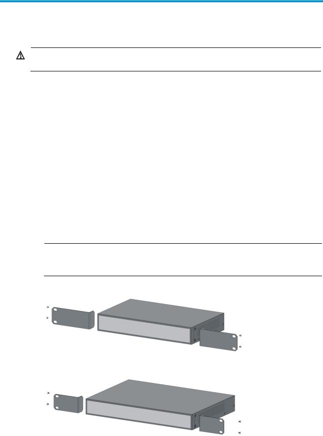
{The HP 1920-16G, 1920-24G, 1920-24G-PoE+ (180W), 1920-24G-PoE+ (370W) and 1920-48G switches use Type-C mounting brackets, as shown in Figure 3.
4.Attach the mounting brackets to both sides of the chassis with screws.
NOTE:
Mounting brackets are used only for securing the switch to the rack. A rack shelf on the rack is used to bear the switch weight.
Figure 1 Attaching Type-A mounting brackets to the switch
Figure 2 Attaching Type-B mounting brackets to the switch
4
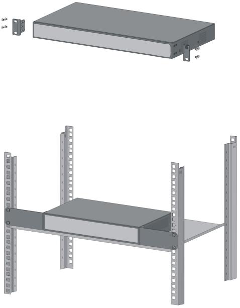
Figure 3 Attaching Type-C mounting brackets to the switch
5.Place the switch on a rack shelf in the rack. Push the switch in until the oval holes in the brackets align with the mounting holes in the rack posts.
6.Attach the mounting brackets to the rack posts with screws.
Figure 4 Attaching Type-A mounting brackets to the rack post
5

Figure 5 Attaching Type-B mounting brackets to the rack post
Figure 6 Attaching Type-C mounting brackets to the rack post
6
Mounting the switch on a workbench
IMPORTANT:
•Reserve a clearance of 10 cm (3.9 in) around the chassis for heat dissipation.
•Do not place heavy objects on the switch.
To mount the switch on a workbench:
1.Verify that the workbench is sturdy and reliably grounded.
2.Place the switch bottom up, and clean the round holes in the chassis bottom with a dry cloth.
3.Attach the rubber feet to the four round holes in the chassis bottom.
4.Place the switch upside up on the workbench.
Figure 7 Attaching rubber feet (HP 1920-24G-PoE+ Switch)
Mounting the switch on a wall
Only the HP 1920-8G switch can be installed on a wall. The type of screws used to mount the switch on the wall depends on the wall type. This section uses a concrete wall as an example.
Wall-mounting anchor kits are user supplied. The screws must be a minimum of 3 mm (0.12 in) in diameter, and the screw head must be a minimum of 6 mm (0.24 in) in diameter.
Figure 8 Wall-mounting anchor kit
To install the switch on a concrete wall:
1.Drill two holes at the same height. Make sure the spacing in between is 160 mm (6.30 in), as shown in Figure 9.
The hole depth and diameter depend on the wall anchors and screws you use. Make sure you can push the anchors to their full depth in the holes.
7
Loading...