


Honeywell T8131A, T8132C, T8131C, T8131B, T8132B User Manual
...T8131A,B,C; T8132A,B,C
Programmable Thermostats
The T8131 and T8132 Thermostats provide energy savings for single-stage heating and cooling applications while providing reliable, precise temperature control.
T8131C
T8132C
T8131/T8132 Models
■HEAT-OFF-COOL system switch.
■AUTO-ON fan switch.
■Separate programs for weekdays and weekends 5 day/2 day.
■Digital LCD display.
■Easy to program and install.
■Precise temperature control.
■Four daily energy saving programs.
■Available in taupe and Premier White™ .
■Compatible with most 24 Vac standing pilot, gas electronic ignition, oil or central electric systems.
T8131 Models Only
■Powered directly from 24 Vac system transformer.
■Green light emitting diode (LED) lights when properly connected.
■Two AA alkaline batteries for backup power recommended.
T8132 Models Only
■Requires two AA alkaline batteries.
■LCD flashes “bAt Lo” indicating low battery power.
■Isolated heating/cooling circuits.
CONTENTS |
|
Specifications ................................................ |
2 |
Ordering Information .................................... |
2 |
Installation .................................................... |
3 |
Programming the Thermostat ....................... |
8 |
Checkout and Settings ................................. |
10 |
Troubleshooting .......................................... |
11 |
Cross Reference .......................................... |
12 |
B.M. • Rev. 61-94 • ©Honeywell Inc. 1994 • Form Number 68-0148—1
T8131A,B,C;T8132A,B,C
SPECIFICATIONS • ORDERING INFORMATION
Specifications
IMPORTANT: The specifications given in this publication do not include normal manufacturing tolerances; therefore, an individual unit may not exactly match the listed specifications. Also, this product is tested and calibrated under closely controlled conditions, and some minor differences in performance can be expected if those conditions are changed.
MODELS:
T8131A/T8132A Programmable Thermostats: Provide eight program keys; with keyboard door.
T8131B/T8132B Programmable Thermostats: Provide eight program keys; without keyboard door.
T8131C/T8132C Programmable Thermostats: Deluxe models, provide twelve program keys including usage key; with keyboard door.
ELECTRICAL RATING: T8131: 24 Vac.
T8132: Battery operated (2 AA alkaline batteries). SYSTEM AND FAN RATINGS:
1.2A run; 7.5A inrush.
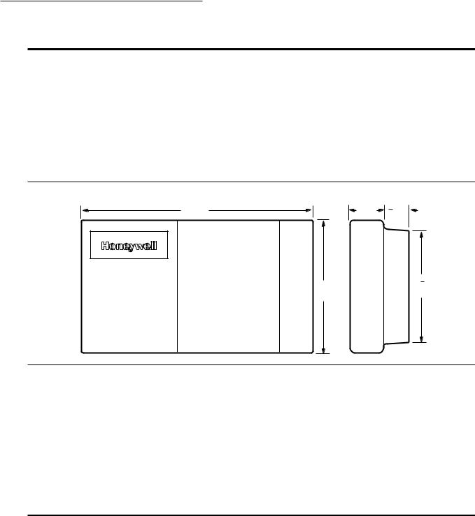
Total cooling and fan load not to exceed 1.2A. DIMENSIONS: See Fig. 1.
Fig. 1—Dimensions in in. [mm] of T8131 and T8132 models.
6 |
7 |
[175] |
1 [25] |
3 |
[19] |
8 |
4 |
4 |
1 |
1 |
|
4 |
|
[102] |
[32] |
|
|
|
|
M9349
MOUNTING MEANS: Position mounting plate directly on wall using two mounting screws and wall anchors provided (See Fig. 2).
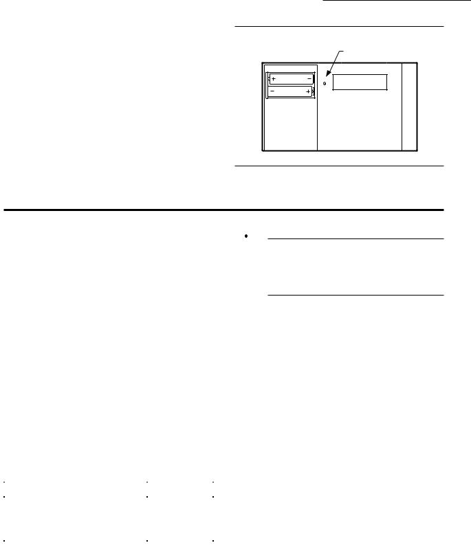
LIGHT EMITTING DIODE (LED): One LED on T8131 models only; lights to indicate proper operation when both sides of the 24 Vac system transformer are properly connected. See Fig. 2 for position of LED.
SET POINT RANGE: 45° F to 88° F [7° C to 31° C].
OPERATING AMBIENT TEMPERATURE RANGE: 40° F to 110° F [4° C to 43° C].
SHIPPING TEMPERATURE RANGE: -20° F to 120° F [-29° C to -49° C].
OPERATING RELATIVE HUMIDITY: 5 percent RH to 90 percent RH; noncondensing.
TIME INDICATION: 12 hour with AM, PM indication.
Ordering Information
When purchasing replacement and modernization products form your TRADELINE® wholesaler or your distributor, refer to the TRADELINE Catalog or price sheets for complete ordering information, or specify—
1.Order Number.
2.Accessories, if desired.
If you have additional questions, need further information, or would like to comment on our products or services, please write or phone:
1.Your local Honeywell Home and Building Control Sales Office (check white pages of phone directory).
2.Home and Building Control Customer Satisfaction Honeywell Inc., 1985 Douglas Drive North Minneapolis, Minnesota 554212-4386 (612) 951-1000.
In Canada—Honeywell Controls Limited/Honeywell Limitée, 740 Ellesmere Road, Scarborough, Ontario M1P 2V9 . International Sales and Service offices in all principal cities of the world. Manufacturing in Australia, Canada, Finland, France, Germany, Japan, Mexico, Netherlands, Spain, Taiwan, United Kingdom, U.S.A.
68-0148—1 |
2 |
T8131A,B,C;T8132A,B,C
SPECIFICATIONS • INSTALLATION
CYCLES PER HOUR ADJUSTMENT:
Heating: Field adjustable to 3, 6, or 9 cph ±10 percent. Cooling: Factory-set at 3 cph ±10 percent (not field
adjustable).
CALIBRATION: Thermostat and thermometer self-cali- brating to ±1.25° F.
FINISH: All models available in taupe and Premier White™. ACCESSORIES:
205013 Isolation Relay kit.
205014 Transformer Plug-in Kit.
205015 International Organization for Standardization Relay and Transformer.
Fig. 2—T8131 LED.
LED LIGHTS WHEN
PROPERLY CONNECTED
POWER
M9365
Installation
WHEN INSTALLING THIS PRODUCT…
1.Read these instructions carefully. Failure to follow instructions can damage product or cause a hazardous condition.
2.Check the ratings given in the instructions and on the product and the compatibility chart below to make sure the product is suitable for your application.
3.Make sure installer is a trained, experienced service technician.
4.After completing installation, use these instructions to check out product operation.
COMPATIBILITY
Check Table 1 to make sure the thermostat is compatible with the intended system.
TABLE 1—COMPATIBILITY CHART.
|
|
|
Compatible |
|
with |
System Type |
T8131/T8132 |
|
|
Gas—Standing Pilot |
Yes |
|
|
Gas—Electronic Ignition |
Yes |
|
|
Gas-Fired Boilers |
Yesa |
Gas—Millivolt |
No |
|
|
Oil-Fired Boilers |
Yesa |
Oil-Fired Furnace |
Yes |
|
|
Electric Furnace |
Yes |
|
|
Electric Air Conditioning |
Yes |
|
|
Baseboard Electric |
No |
(120/240 Line Volt) |
|
|
|
Heat pumps/Multistage Equipment |
No |
|
|
 WARNING
ELECTROCUTION HAZARD CAN CAUSE PROPERTY DAMAGE, SEVERE INJURY, OR DEATH.
Disconnect power supply before wiring to prevent electrical shock or equipment damage.
LOCATION
Locate the thermostat about 5 ft [1.5m] above the floor in an area with good air circulation at average temperature.
Do not mount the thermostat where it may be affected by:
—drafts or dead spots behind doors and in corners.
—hot or cold air ducts.
—concealed pipes and chimneys.
—unheated (uncooled) areas such as an outside wall behind the thermostat.
MOUNT THERMOSTAT MOUNTING PLATE (FIG. 2)
Position mounting plate on wall. Use spirit level to make sure mounting plate is level. Use a pencil to mark the two mounting holes.
Level for appearance only; thermostat will function properly even when not level. Tighten mounting screws.
Remove mounting plate from wall, and drill 3/16 inch holes in wall (if drywall) as marked. For firmer material such as plaster or wood, drill 7/32 inch holes. Gently tap anchors (provided) into drilled holes until flush with the wall.
Reposition mounting plate over holes, pulling wires through wiring opening. Loosely insert two mounting screws into holes.
Not compatible with any 120/240 volt circuit. Not designed for steam or gravity systems.
aCompatible with 2-wire Honeywell zone valves. Isolating relay required for 3-wire thermostats for zone valves. Not compatible with 2-wire White Rodgers no. 1361 Valves.
3 |
68-0148—1 |

T8131A,B,C;T8132A,B,C
INSTALLATION
Fig. 3—Mounting thermostat mounting plate.
WALL
ANCHORS (2)
WIRES THROUGH
WALL OPENING
WALL
 MOUNTING
PLATE
MOUNTING |
|
SCREWS (2) |
M1718 |
WIRING
All wiring must comply with all applicable electrical codes, ordinances, and regulations. Follow instructions provided with the controlled equipment.
Loosen the terminal screws and slip each wire beneath its matching terminal. See Fig. 4 for wiring insertion techniques. Tighten terminals securely.
Plug the hole in the wall with insulation to help prevent drafts from adversely affecting thermostat operation.
T8131 Models
Run the required number of wires to the thermostat location (check the appropriate wiring diagram). Refer to Figs. 5 through 7 for typical wiring diagrams.
T8132 Models
Run the required number of wires to the thermostat location (check the appropriate wiring diagram). Refer to Figs. 8 through 11 for typical wiring diagrams.
In 5-wire installations only, be sure to remove the fac- tory-installed jumper connecting terminals R and Rc.
Fig. 4—Proper wiring technique.
PROPER WIRING TECHNIQUE
|
INSERT |
|
5/16 in. |
STRAIGHT |
|
UNDER |
||
[8 mm] |
||
SCREW HEAD |
||
STRIP |
||
|
||
|
END OF WIRE |
|
|
VISIBLE HERE M3825 |
Fig. 5—3-wire heat-only application.
3-WIRE HEAT-ONLY
A |
|
|
B |
|
|
W |
Y G |
|
C |
R |
|
HEATING |
|
1 |
|
L1 |
|
RELAY OR |
|
|
VALVE COIL |
|
(HOT) |
|
|
|
|
|
L2 |
1 POWER SUPPLY. PROVIDE DISCONNECT MEANS |
|
|
AND OVERLOAD PROTECTION AS REQUIRED. |
M9213 |
|
Fig. 6—4-wire cool-only application.
4-WIRE COOL-ONLY
A
B
W Y G
C R
COOLING
CONTACTOR
COIL
FAN |
1 |
|
L1 |
||
RELAY |
||
|
(HOT) |
|
|
L2 |
1 POWER SUPPLY. PROVIDE DISCONNECT MEANS AND
OVERLOAD PROTECTION AS REQUIRED. |
M9212 |
|
|
Fig. 7—5-wire heat/cool application.
5-WIRE HEAT/COOL
A
B
W Y G
HEATING RELAY OR VALVE COIL
C R
FAN |
RELAY |
|
COOLING |
|
|
1 |
||
|
CONTACTOR |
|
|
|
|
L1 |
|
COIL |
|
|
|
|
|
|
|
|
|
|
(HOT) |
|
|
|
|
|
|
|
L2 |
|
|
|
|
|
|
|
|
|
|
|
|
|
|
1 POWER SUPPLY. PROVIDE DISCONNECT MEANS AND
OVERLOAD PROTECTION AS REQUIRED. |
M9214 |
68-0148—1 |
4 |
 Loading...