


BF2
Table of contents
 Loading...

The engine exhaust from this
product contains chemicals
known to the State of California to
cause cancer, birth defects, or
other reproductive harm.
The information and specifications included in this publication were in effect at the
time of approval for printing. Honda Motor Co., Ltd. reserves the right, however, to
discontinue or change specifications or design at any time without notice and without
incurring any obligation whatever. No part of this publication may be reproduced
without written permission.
Keep this owner’s manual handy, so you can refer to it at any time. This owner’s
manual is considered a permanent part of the outboard motor and should remain with
the outboard motor if resold.

1
INTRODUCTION
Congratulations on your selection of
a Honda outboard motor. We are
certain you will be pleased with your
purchase of one of the finest
outboard motors on the market.
We want to help you get the best
results from your new outboard
motor and to operate it safely. This
manual contains the information on
how to do that; please read it
carefully.
As you read this manual you will
find information preceded by a
symbol. That information
is intended to help you avoid damage
to your outboard motor, other
property, or the environment.
We suggest you read the warranty
policy to fully understand its
coverage and your responsibilities of
ownership. The warranty policy is a
separate document that should have
been given to you by your dealer.
When your outboard motor needs
scheduled maintenance, keep in mind
that your Honda marine dealer is
specially trained in servicing Honda
outboard motors. Your Honda marine
dealer is dedicated to your
satisfaction and will be pleased to
answer your questions and concerns.
2002 Honda Motor Co., Ltd. All
Rights Reserved

−
−
−
−
−
−
2
A FEW WORDS ABOUT
SAFETY
INTRODUCTION
Safety Messages
Safety Headings
Safety Labels
Safety Section
Instructions
IMPORTANT SAFETY INFORMATION.
OUTBOARD MOTOR SAFETY.
Your safety and the safety of others
are very important. And using this
outboard motor safely is an important
responsibility.
To help you make informed
decisions about safety, we have
provided operating procedures and
other information on labels and in
this manual. This information alerts
you to potential hazards that could
hurt you or others.
Of course, it is not practical or
possible to warn you about all the
hazards associated with operating or
maintaining an outboard motor. You
must use your own good judgment.
You will find important safety information in a variety of forms, including:
This entire book is filled with important saf ety information please read it
carefully.
preceded by a safety alert symbol and one of
three signal words, DANGER, WARNING, or CAUTION.
These signal words mean:
such as
on the outboard motor.
such as
how to use this outboard motor correctly and safely.
You WILL be KILLED or SERIOUSLY
HURT if you don’t follow instructions.
You CAN be KILLED or SERIOUSLY
HURT if you don’t follow instructions.
You CAN be HURT if you don’t follow
instructions.

?
?
3
CONTENTS
...................................OUTBOARD MOTOR SAFETY . 6
................IMPORTANT SAFETY INFORMATION . 6
................................SAFETY LABEL LOCATIONS . 8
....................................CONTROLS AND FEATURES . 9
CONTROLS AND FEATURE
..................................IDENTIFICATION CODES . 9
....COMPONENT AND CONTROL LOCATIONS . 10
..............................................................CONTROLS . 11
....................Engine Stop Switch and Switch Clip . 11
.........................................................Choke Knob . 11
................................Throttle lever (SA type only) . 12
..............Throttle Grip (SHA/SCHA/LCHA type) . 12
..........................................Throttle Friction Knob . 12
...................................................Fuel Valve Lever . 13
................................................Recoil Starter Grip . 13
.............................Engine Cover Retaining Strap . 13
.............................Transom Angle Adjusting Bolt . 14
...............................................................Tilt Lever . 14
............................................Steering Friction Bolt . 15
........................................................Clamp Screws . 15
.............................................Fuel Cap Vent Knob . 15
................................................OTHER FEATURES . 16
..............Centrifugal Clutch (SCHA/LCHA type) . 16
...............................Oil Level Inspection Window . 16
....................................................................Anode . 16
..........................................................INSTALLATION . 17
.....................................POWER REQUIREMENTS . 17
...................BOAT TRANSOM REQUIREMENTS . 17
..................................INSTALLATION POSITION . 17
.......................................................ATTACHMENT . 18
.....................TRANSOM ANGLE ADJUSTMENT . 19
................................................BEFORE OPERATION . 20
.....ARE YOU READY TO GET UNDER WAY . 20
IS YOUR OUTBOARD MOTOR
................................................READY TO GO . 20

4
CONTENTS
................................................................OPERATION . 22
....................SAFE OPERATING PRECAUTIONS . 22
.......................................BREAK-IN PROCEDURE . 22
.....................TRANSOM ANGLE ADJUSTMENT . 22
......................................STARTING THE ENGINE . 23
.....................................EMERGENCY STARTING . 26
.......................................STOPPING THE ENGINE . 28
................................Emergency Engine Stopping . 28
.......................................Normal Engine Stopping . 28
......................................THROTTLE OPERATION . 30
............REVERSING THE OUTBOARD MOTOR . 31
...............................................................STEERING . 32
................................................................CRUISING . 33
...............MOORING, BEACHING, LAUNCHING . 34
..............SERVICING YOUR OUTBOARD MOTOR . 36
...........THE IMPORTANCE OF MAINTENANCE . 36
.....................................MAINTENANCE SAFETY . 37
TOOL KIT AND EMERGENCY STARTER
.....................................................................ROPE . 38
...............................MAINTENANCE SCHEDULE . 39
ENGINE COVER REMOVAL AND
..................................................INSTALLATION . 41
............................................Engine Oil Level Check . 41
....................................................Engine Oil Change . 41
..................................Engine Oil Recommendations . 43
.....................................................Lubrication Points . 44
....................................................Spark Plug Service . 45
.............................................................REFUELING . 47
...............................FUEL RECOMMENDATIONS . 48
.................................Recoil Starter Rope Inspection . 49
..................................................Anode Replacement . 49
..............................................Propeller Replacement . 50

5
CONTENTS
....................................................................STORAGE . 51
...................................STORAGE PREPARATION . 51
..........................................Cleaning and Flushing . 51
........................................................................Fuel . 51
.............................................................Engine Oil . 52
...................................STORAGE PRECAUTIONS . 53
...............................REMOVAL FROM STORAGE . 54
........................................................TRANSPORTING . 55
WITH OUTBOARD MOTOR INSTALLED
.............................................................ON BOAT . 55
WITH OUTBOARD MOTOR REMOVED
.......................................................FROM BOAT . 55
....TAKING CARE OF UNEXPECTED PROBLEMS . 56
..................................ENGINE WILL NOT START . 56
HARD STARTING OR STALLS AFTER
...........................................................STARTING . 58
..ENGINE WILL NOT DRIVE THE PROPELLER . 59
..........................................SUBMERGED MOTOR . 60
..TECHNICAL AND CONSUMER INFORMATION . 62
...............................TECHNICAL INFORMATION . 62
......................................Serial Number Locations . 62
Carburetor Modification for High Altitude
...........................................................Operation . 63
..................................................Oxygenated Fuels . 64
.................Emission Control System Information . 65
..............................................................Star Label . 67
........................................................Specifications . 69
...............................CONSUMER INFORMATION . 70
..............................Customer Service Information . 70
..................................................WIRING DIAGRAMS . 71
...........................................................................INDEX . 72

6
IMPORTANT SAFETY
INFORMATION
Operator Responsibility
OUTBOARD MOTOR SAFETY
It is the operator’s responsibility to
provide the necessary safeguards
to protect people and property.
Know how to stop the engine
quickly in case of emergency.
Understand the use of all controls.
Attach the emergency stop switch
lanyard securely to the operator.
Stop the engine immediately if
anyone falls overboard, and do not
run the engine while the boat is
near anyone in the water.
Always stop the engine if you
must leave the controls for any
reason.
Always wear a PFD (Personal
Flotation Device) while on the
boat.
Familiarize yourself with all laws
and regulations relating to boating
and the use of outboard motors.
Be sure that anyone who operates
the outboard motor receives proper
instruction.
Be sure the outboard motor is
properly mounted on the boat.
Do not remove the engine cover
while the engine is running.
Most accidents can be prevented if
you follow all instructions in this
manual and on the outboard motor.
The most common hazards are
discussed below, along with the best
way to protect yourself and others.
Honda BF2D outboard motor is
designed for use with boats that have
a suitable manufacturer’s power
recommendation. Other uses can
result in injury to the operator or
damage to the outboard motor and
other property.

7
Carbon Monoxide HazardRefuel With Care
OUTBOARD MOTOR SAFETY
Exhaust gas contains poisonous
carbon monoxide. Avoid inhalation
of exhaust gas. Never run the engine
in a closed garage or confined area.
Gasoline is extremely flammable,
and gasoline vapor can explode.
Refuel outdoors, in a well-
ventilated area, with the engine
stopped. Never smoke near
gasoline, and keep other flames
and sparks away.
Refuel carefully to avoid spilling
fuel. Avoid overfilling the fuel
tank.
After refueling, tighten the filler
cap securely. If any fuel is spilled,
make sure the area is dry before
starting the engine.
8
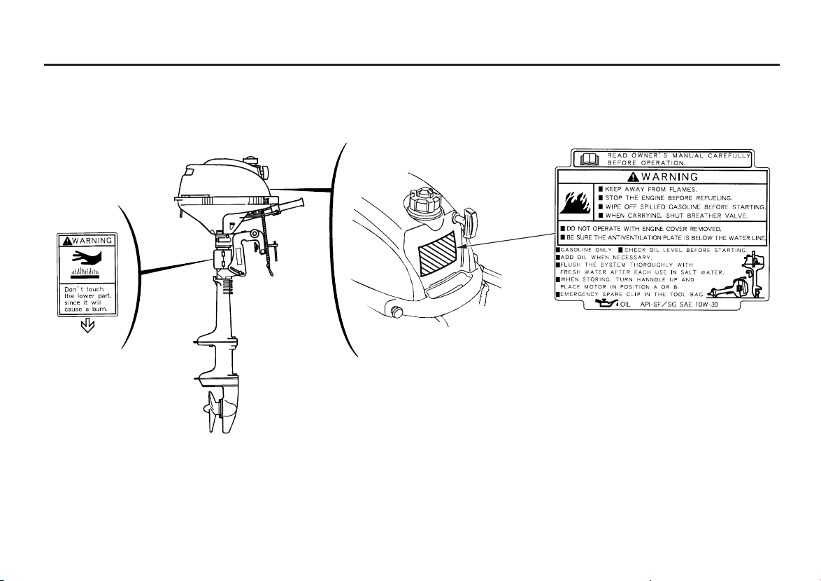
SAFETY LABEL LOCATIONS
OUTBOARD MOTOR SAFETY
The labels shown here contain important safety information. Please read them carefully. These labels are considered
permanent parts of your outboard motor. If a label comes off or becomes hard to read, contact an authorized Honda
Marine servicing dealer for a replacement.

9
CONTROL AND FEATURE IDENTIFICATION CODES
CONTROLS AND FEATURES
Type
Model
Throttle Lever
Throttle Grip
Centrifugal Clutch
Shaft Length
BF2D
SA SHA SCHA LCHA
S
L
Refer to this chart for an explanation of the Type Codes used in this manual to identify control and feature applications.
Destination
A
TYPE CODE(example)
SCH
Throttle type
H=Throttle grip
None=Throttle lever
Shaft length
A=America
S=Short shaft
L=Long shaft
Centrifugal clutch
C=With centrifugal clutch
None=Without centrifugal clutch
10
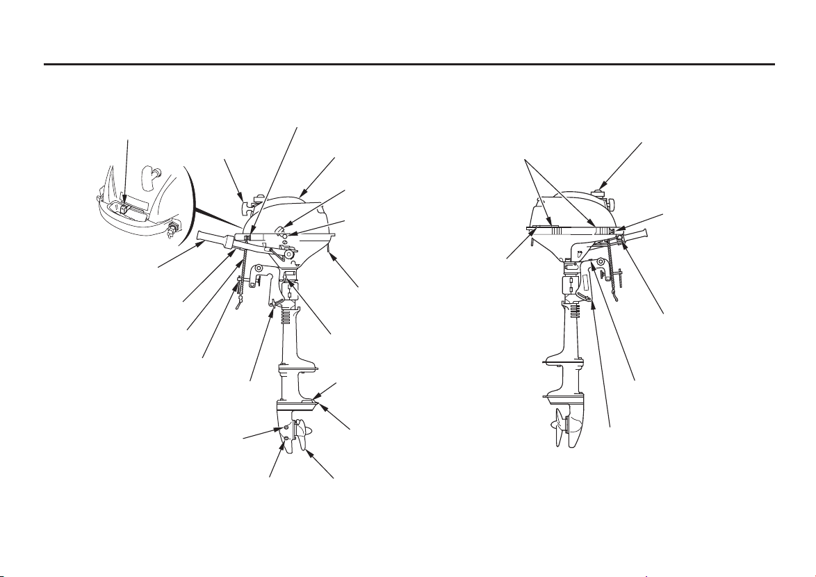
COMPONENT AND CONTROL LOCATIONS
CONTROLS AND FEATURES
THROTTLE LEVER
(SA type only)
LCHA type is shown
ENGINE STOP SWITCH
ENGINE COVER
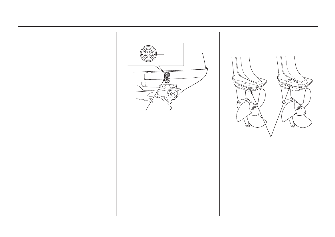
OIL FILLER CAP
(inside the engine cover)
ENGINE COVER
RETAINING STRAP
ANODE METAL
ANTIVENTILATION
PLATE
PROPELLER
FUEL FILLER CAP
CHOKE KNOB
STERN BRACKET
TILT HANDLE
THROTTLE GRIP
(SHA/SCHA/LCHA type)
EMERGENCY ENGINE
STOP SWITCH LANYARD
ADJUSTING ROD
CLAMP SCREW
GEAR OIL LEVEL PLUG
GEAR OIL DRAIN PLUG
STARTER GRIP
CASE PROTECTOR
OIL LEVEL INSPECTION
WINDOW
THROTTLE GRIP
FRICTION KNOB
(SHA/SCHA/LCHA type)
TILT LEVER
FUEL VALVE LEVER
STEERING
FRICTION BOLT
11
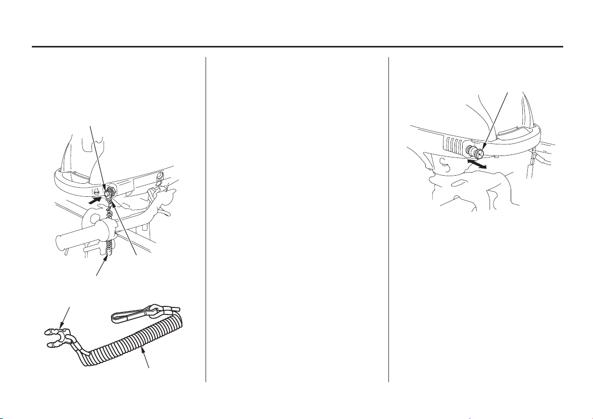
CONTROLS
Engine Stop Switch and Switch
Clip
Choke Knob
CONTROLS AND FEATURES
LANYARD
SWITCH CLIP
LANYARD
ENGINE STOP SWITCH
SWITCH CLIP
OOPPEENN
CHOKE KNOB
CLOSED
The engine stop switch has controls
for normal engine stopping and
emergency engine stopping.
The switch clip must be inserted in
the engine stop switch in order for
the engine to start and run. The
lanyard should be attached to the
operator’s PFD (Personal Flotation
Device) or worn around the wrist as
shown.
When used as described, the engine
stop switch and lanyard system stops
the engine if the operator falls away
from the controls.
A spare switch clip is supplied with
the tool kit.
The CLOSED position enriches the
fuel mixture for starting a cold
engine.
The OPEN position provides the
correct fuel mixture for operation
after starting, and for restarting a
warm engine.
The choke knob opens and closes the
choke valves in the carburetor.
12
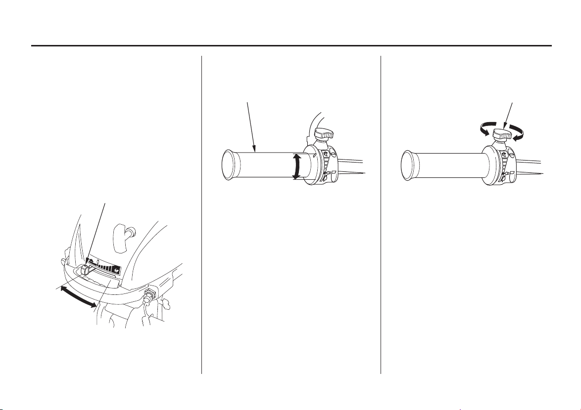
Throttle Friction KnobThrottle GripThrottle Lever (SA type only)
(SHA/SCHA/LCHA type) (SHA/SCHA/LCHA type)
CONTROLS AND FEATURES
THROTTLE GRIP
FIX
SLOW
FAST
THROTTLE LEVER
SLOW
FAST
THROTTLE GRIP FRICTION KNOB
RELEASE
The throttle grip controls engine
speed.
An index mark on the tiller arm
shows throttle position and is helpf ul
for setting the throttle correctly when
starting (p. ).
The throttle lever controls engine
speed.
An index mark on the engine cover
shows throttle position and is helpf ul
for setting the throttle correctly when
starting (p. ).
The throttle friction knob adjusts
resistance to throttle grip rotation.
Turn the knob clockwise to increase
friction for holding a throttle setting
while cruising.
Turn the knob counterclockwise to
decrease friction for easy throttle grip
rotation.
24
24
13
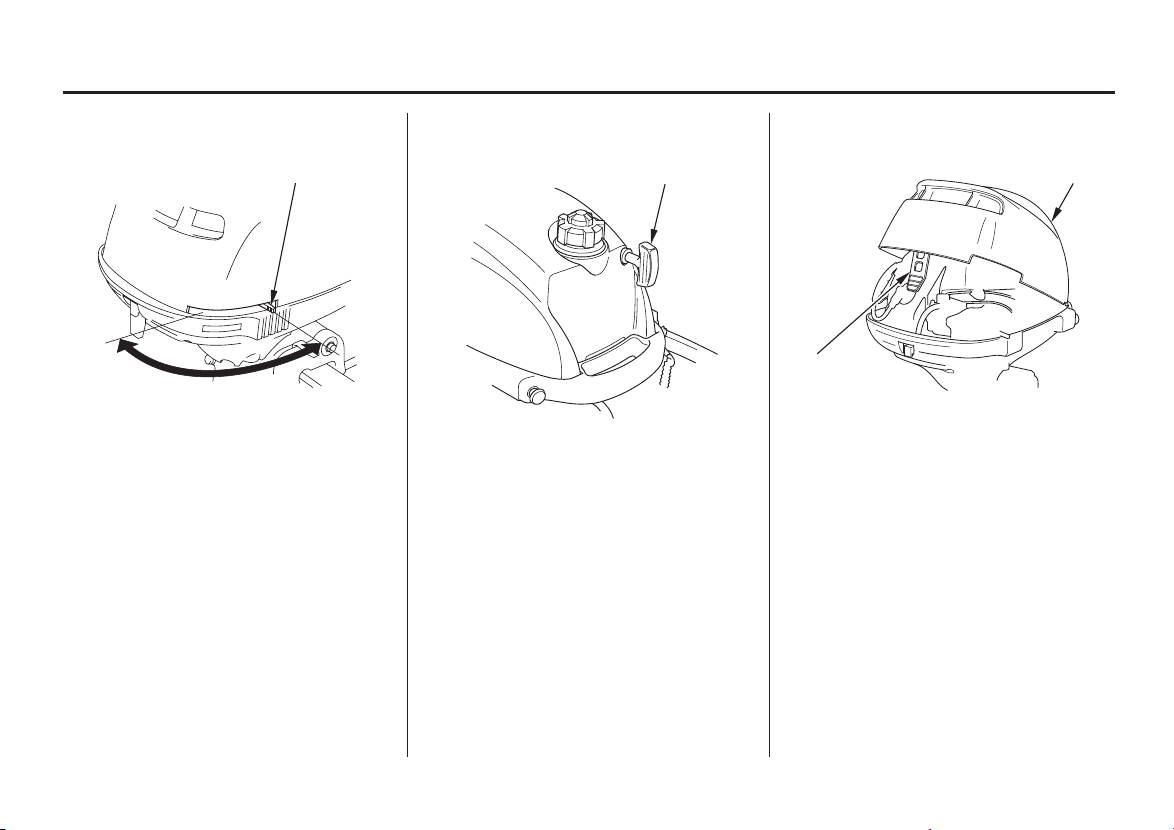
Recoil Starter GripFuel Valve Lever Engine Cover Retaining Strap
CONTROLS AND FEATURES
OFF
ON
FUEL VALVE LEVER ENGINE COVER
STRAP
RECOIL STARTER GRIP
Pull the starter grip to operate the
recoil starter for starting the engine.
The fuel valve opens and closes the
connection between the fuel tank and
the carburetor.
The fuel valve lever must be in the
ON position for the engine to run.
When the engine is not in use, leave
the fuel valve lever in the OFF
position to prevent carburetor
flooding and to reduce the possibility
of fuel leakage.
Use the retaining strap to hold the
engine cover closed. Do not remove
the engine cover while the engine is
running.
14
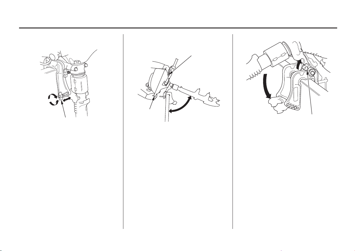
Transom Angle Adjusting Bolt Tilt Lever
CONTROLS AND FEATURES
REAR CARRYING HANDLE
FRONT
CARRYING
HANDLE
75°
TILT LEVER
ADJUSTING BOLT AND WING NUT
The transom angle adjusting bolt is
used to adjust the angle of the
outboard motor in the normal
operating position (see page ).
Loosen the wing nut to free the
adjusting bolt.
Adjust the angle of the outboard
motor, and tighten the wing nut. Be
sure that the bolt head and wing nut
are seated in one of the four recesses
in the adjustment slot.
To return the outboard motor to the
normal running position, hold the
outboard motor and pull the tilt lever,
then slowly lower the outboard motor.
The tilt lever enables the outboard
motor to be tilted for shallow water
operation, beaching, launching, or
mooring.
Tilt the outboard motor by holding
the carrying handles, as shown. The
spring-loaded tilt lever will
automatically move into position and
hold the outboard motor when it
reaches approximately 75°.
22
15
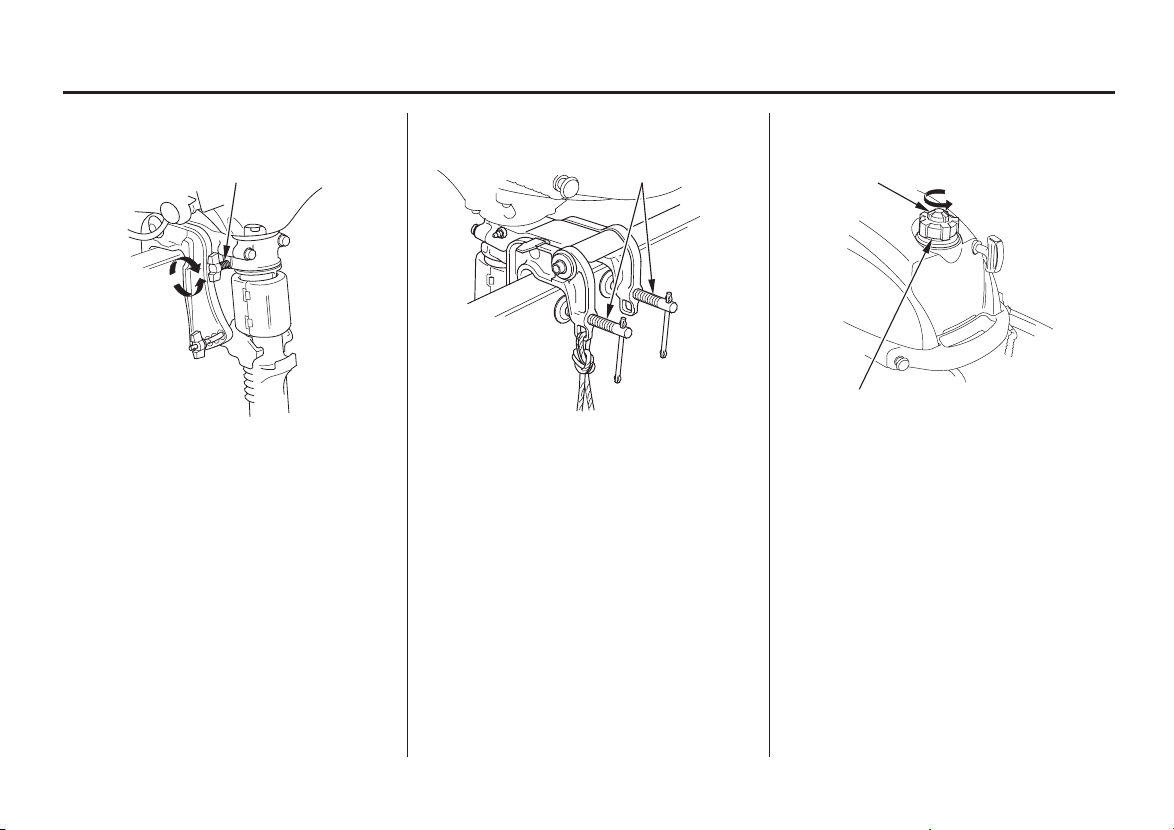
Steering Friction Bolt Clamp Screws Fuel Cap Vent Knob
CONTROLS AND FEATURES
STEERING FRICTION BOLT
TTOO IINNCCRREEAASSEE
FFRRIICCTTIIOONN
CLAMP SCREWS VENT KNOB
OPEN
FUEL FILLER CAP
TTOO DDEECCRREEAASSEE
FFRRIICCTTIIOONN
Less friction allows the outboard
motor to turn more easily. More
friction helps to hold steady course
while cruising or to prevent the
outboard motor from swinging while
trailering the boat.
The steering friction bolt adjusts
steering resistance.
Use the clamp screws to secure the
outboard motor to the transom.
The cap is provided with a vent knob
to seal the fuel tank. Open the vent
knob 2 or 3 turns before starting the
engine (p. ).23
16
AnodeOTHER FEATURES
Centrifugal Clutch (SCHA/
LCHA type)
Oil Level Inspection Window
CONTROLS AND FEATURES
OIL LEVEL INSPECTION WINDOW
UUPPPPEERR LLIIMMIITT
LLOOWWEERR LLIIMMIITT
Short shaft type Long shaft type
ANODE
Use the oil level inspection window
to check the engine oil level with the
engine stopped and the outboard
motor in the upright position.
The anode is made of a sacrificial
material that helps to protect the
outboard motor from corrosion.
The centrifugal clutch automatically
engages and transmits power when
engine speed is increased above
approximately 2,700 rpm. At idle
speed, the clutch is disengaged.
−
16.5 in (418 mm)
22.5 in (571 mm)
17
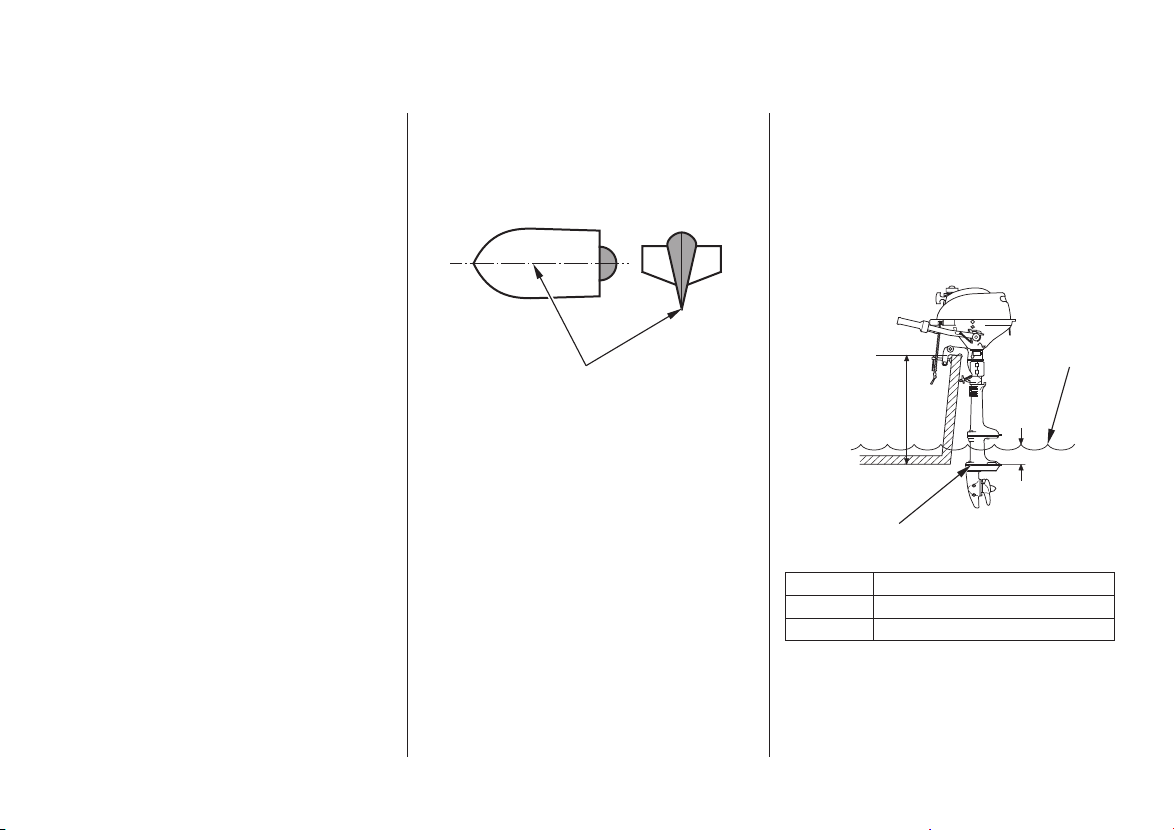
POWER REQUIREMENTS
INSTALLATION POSITION
INSTALLATION
CENTER LINE
TTRRAANNSSOOMM HHEEIIGGHHTT
5.9 in (150 mm)
WATER
SURFACE
ANTIVENTILATION PLATE
Correct and secure installation is
essential for safe boating and good
performance. Follow the installation
instructions provided in this manual.
Transom Height
Before installation, check to be sure
that the outboard motor does not
exceed the recommended maximum
horsepower for the boat on which it
is to be installed. Refer to the boat’s
certification plate for recommended
maximum horsepower. If the
certification plate information is not
available, contact the boat dealer or
manufacturer.
For most applications, the outboard
motor should have a horsepower
rating which provides 80% of the
maximum recommended horsepower
for the boat.
The antiventilation plate of the
outboard motor should be 0 2.0
inches below the bottom of the boat.
With the boat in the water and loaded,
the antiventilation plate should be
about 5.9 inches below the surface of
the water.
Type:
S:
L:
Install the outboard motor on the
center of the boat transom.
18
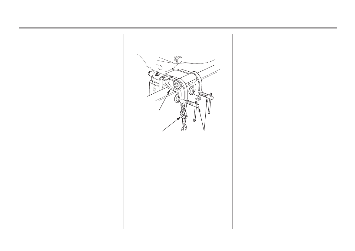
ATTACHMENT
INSTALLATION
CLAMP SCREW
STERN BRACKET
SAFETY ROPE
If the outboard motor is installed too
low, the boat will squat and be hard
to plane, it will tend to porpoise, and
high-speed stability will be reduced.
If the outboard motor is installed too
high, that will cause ventilation.
Optimum installation height varies
with boat type and bottom shape.
Contact the boat manufacturer for
any special recommendations that are
unique to a specific model of boat.
If the transom needs to be modified
to accommodate the outboard motor,
contact the boat manufacturer and
follow their recommendations for
corrective action.
Attach the stern bracket to the boat
transom by tightening the clamp
screws.
Attach a rope from the boat to the
hole in the stern bracket. This will
help to prevent accidental loss of the
outboard motor.

19
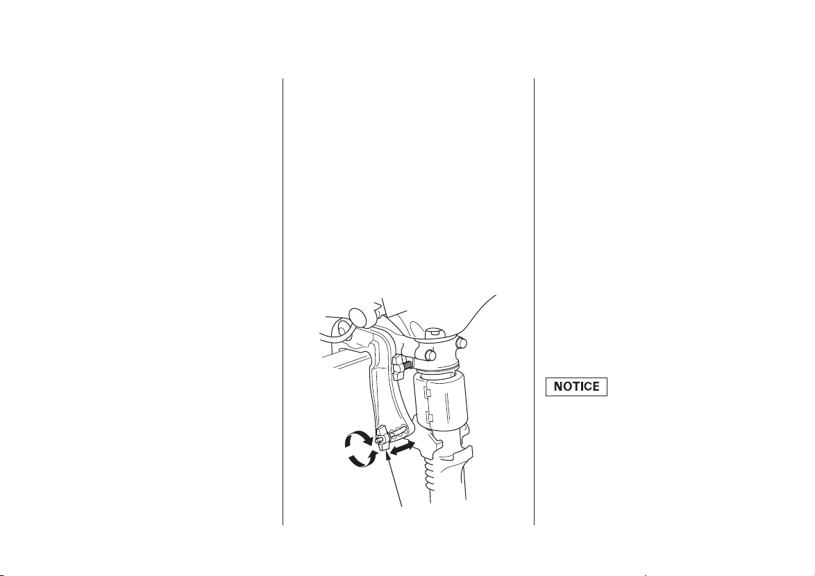
TRANSOM ANGLE
ADJUSTMENT
INSTALLATION
Use the transom angle adjustment
bolt (p. ) to adjust the angle of the
outboard motor so the propeller is
perpendicular to the surface of the
water.
22

?
?
Improperly maintaining
this outboard motor, or
failing to correct a problem
before operation, could
cause a malfunction in
which you could be
seriously injured.
Always perform a
preoperation inspection
before each operation, and
correct any problem.
20
ARE YOU READY TO GET
UNDER WAY
Safety
Knowledge
IS YOUR OUTBOARD
MOTOR READY TO GO
BEFORE OPERATION
Your safety is your responsibility. A
little time spent in preparation will
significantly reduce your risk of
injury.
Read and understand this manual.
Know what the controls do and how
to operate them.
Familiarize yourself with the
outboard motor and its operation
before you get under way. Know
what to do in case of emergencies.
Familiarize yourself with all laws
and regulations relating to boating
and the use of outboard motors.
Always wear a PFD (Personal
Flotation Device) while on the boat.
Attach the emergency stop switch
lanyard securely to your PFD or to
your wrist.
For your safety, and to maximize the
service life of your equipment, it is
very important to take a few
moments before you operate the
outboard motor to check its condition.
Be sure to take care of any problem
you find, or have your authorized
Honda Marine dealer correct it,
before you operate the outboard
motor.

21
Safety Inspection Maintenance Inspection
BEFORE OPERATION
Look around the outboard motor
for signs of oil or gasoline leaks.
Check the engine oil level (p. ).
Running the engine with a low oil
level can cause engine damage.
Wipe up any spills before starting
the engine.
Check the stern bracket to be sure
the outboard motor is securely
installed.
Check that all controls are
operating properly.
Replace any damaged parts.
Check that all fasteners are in
place and securely tightened.
Check to be sure the propeller is
undamaged (p. ).
Check that the anode is securely
attached to the antiventilation plate
(p. ) and is not excessively
worn. The anode helps to protect
the outboard motor from corrosion.
Make sure the tool kit and
emergency starter rope are
onboard (p. ). Replace any
missing items.
Check the fuel level in the fuel
tank (p. ).
41
38
50
49
47
22
SAFE OPERATING
PRECAUTIONS
BREAK-IN PROCEDURE
TRANSOM ANGLE
ADJUSTMENT
OPERATION
ADJUSTING BOLT AND WING NUT
IMPORTANT SAFETY
INFORMATION
BEFORE OPERATION.
To prevent damage to the motor or
boat, make sure the transom angle
adjusting bolt is locked.
To safely realize the full potential of
this outboard motor, you need a
complete understanding of its
operation and a certain amount of
practice with its controls.
Before operating the outboard motor
for the first time, please review the
on page and the
chapter titled
For your safety, avoid starting or
operating the engine in an enclosed
area. Your engine’s exhaust contains
poisonous carbon monoxide gas
which can collect rapidly in an
enclosed area and cause illness or
death.
The transom angle adjusting bolt is
used to adjust the angle of the
outboard motor in the normal
operating position (p. ).
To adjust, first tilt the outboard
motor so it is not resting on the bolt.
There are four adjustment positions.
Loosen the wing nut to free the
adjusting bolt.
Adjust the angle of the motor, and
tighten the wing nut. Be sure that
the bolt head and wing nut are
seated in one of the four
adjustment positions.
Proper break-in procedure allows the
moving parts to wear in smoothly for
best performance and long service
life.
For the first 10 hours, run the
outboard motor at low speed, and
avoid full-throttle operation.
7
33
1.
2.
Loading...