

Page 1
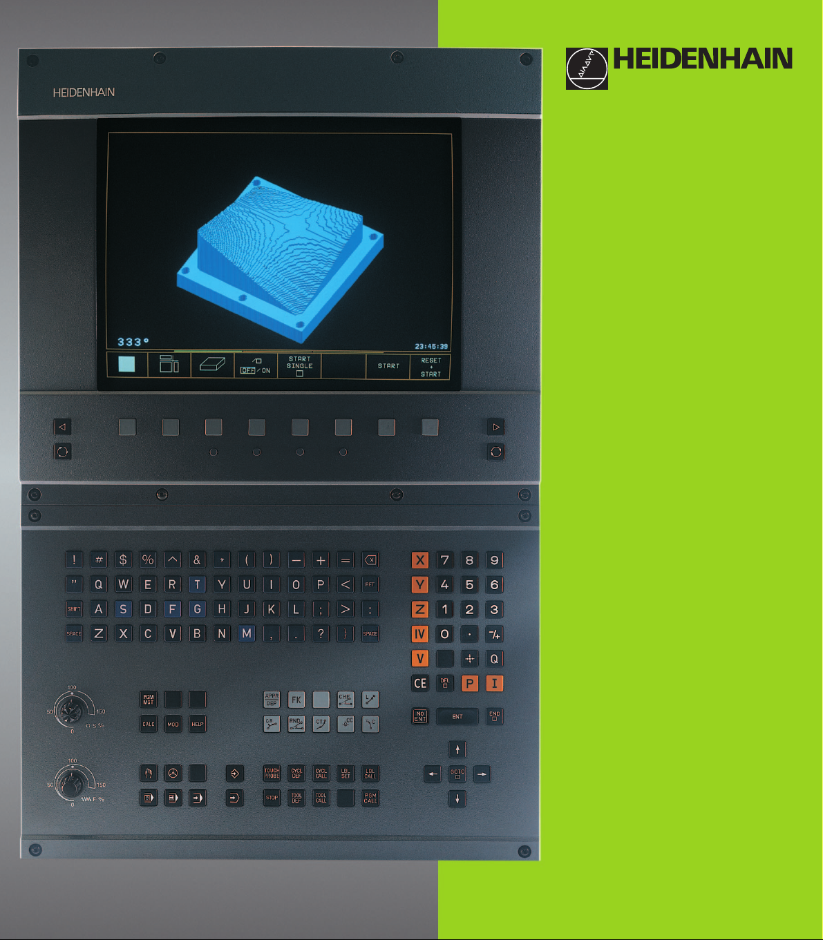
TNC 410
NC-Software
286 060-xx
286 080-xx
User’s Manual
Conversational
Programming
English (en)
6/2001
Page 2
Controls on the visual display unit
0
0
Split screen layout
Toggle display between machining
and programming modes
Soft keys for selecting functions
in screen
Shift soft-key rows for the soft keys
Change screen settings
Controls on the TNC
(BC 120 only)
Typewriter keyboard for entering letters
and symbols
Q
W E
G
F S T M
R
T
Y
Comments
ISO programs
File name
Machine operating modes
MANUAL OPERATION
ELECTRONIC HANDWHEEL
POSITIONING WITH MDI
PROGRAM RUN, SINGLE BLOCK
PROGRAM RUN, FULL SEQUENCE
Programming modes
PROGRAMMING AND EDITING
TEST RUN
Program/file management, TNC functions
Select or delete programs and files
PGM
MGT
External data transfer
PGM
Enter program call in a program
CALL
MOD
MOD functions
HELP
HELP functions
CALC
Pocket calculator
Moving the cursor, going directly to blocks, cycles
and parameter functions
Move highlight
GOTO
Go directly to blocks, cycles and parameter
functions
Override control knobs for feed rate/spindle speed
100
50
1
5
F %
0
100
50
1
5
S %
0
Programming path movements
APPR
Approach/depart contour
DEP
Free contour programming
L
Straight line
CC
Circle center/pole for polar coordinates
C
Circle with center
CR
Circle with radius
CT
Tangential circle
CHF
Chamfer
RND
Corner rounding
Tool functions
TOOL
TOOL
DEF
Enter or call tool length and radius
CALL
Cycles, subprograms and program section
repeats
CYCL
CYCL
DEF
LBL
SET
Define and call cycles
CALL
LBL
Enter and call labels for
CALL
subprogramming and program
section repeats
STOP
Program stop in a program
TOUCH
Enter touch probe functions in a program
PROBE
Coordinate axes and numbers, editing
X
...
...
0
Select coordinate axes or enter
V
them in a program
Numbers
9
Decimal point
/
+
Change arithmetic sign
Polar coordinates
P
Incremental dimensions
Q parameters
Q
Capture actual position
NO
Skip dialog questions, delete words
ENT
ENT
END
End block
CE
Clear numerical entry or TNC error message
DEL
Abort dialog, delete program section
Confirm entry and resume
dialog
Page 3
Page 4

TNC Models, Software and
Features
This manual describes functions and features provided by
the TNCs with the following NC software number.
TNC Model NC Software No.
TNC 410 286 060-xx
TNC 410 286 080-xx
The machine tool builder adapts the useable features of the
TNC to his machine by setting machine parameters. Therefore, some of the functions described in this manual may
not be among the features provided by your machine tool.
TNC functions that may not be available on your machine
include:
■ Probing function for the 3-D touch probe
■ Digitizing option
■ Tool measurement with the TT 120
■ Rigid tapping
Please contact your machine tool builder to become familiar
with the individual implementation of the control on your
machine.
Many machine manufacturers, as well as HEIDENHAIN,
offer programming courses for the TNCs. We recommend
these courses as an effective way of improving your
programming skill and sharing information and ideas with
other TNC users.
Contents
Location of use
The TNC complies with the limits for a Class A device in
accordance with the specifications in EN 55022, and is
intended for use primarily in industrially-zoned areas.
IHEIDENHAIN TNC 410
Page 5

II
Contents
Page 6

Contents
Introduction
1
Manual Operation and Setup
Positioning with Manual Data Input
Programming: Fundamentals of NC,
File Management, Programming Aids
Programming: Tools
Programming: Programming Contours
Programming: Miscellaneous Functions
Programming: Cycles
Programming: Subprograms and
Program Section Repeats
Programming: Q Parameters
Test Run and Program Run
3-D Touch Probes
2
3
4
5
6
7
8
9
10
11
12
Digitizing
MOD Functions
Tables and Overviews
13
14
15
IIIHEIDENHAIN TNC 410
Page 7

1 INTRODUCTION ..... 1
1.1 The TNC 410 ..... 2
1.2 Visual Display Unit and Keyboard ..... 3
Contents
1.3 Modes of Operation ..... 5
1.4 Status Displays ..... 9
1.5 Accessories: HEIDENHAIN 3-D Touch Probes and Electronic Handwheels ..... 12
2 MANUAL OPERATION AND SETUP ..... 13
2.1 Switch-On ..... 14
2.2 Moving the Machine Axes ..... 15
2.3 Spindle Speed S, Feed Rate F and Miscellaneous Functions M ..... 18
2.4 Setting the Datum (Without a 3-D Touch Probe) ..... 19
3 POSITIONING WITH MANUAL DATA INPUT (MDI) ..... 21
3.1 Programming and Executing Simple Positioning Blocks ..... 22
4 PROGRAMMING: FUNDAMENTALS OF NC, FILE MANAGEMENT, PROGRAMMING AIDS ..... 25
4.1 Fundamentals of NC ..... 26
4.2 File Management ..... 31
4.3 Creating and Writing Programs ..... 34
4.4 Interactive Programming Graphics ..... 39
4.5 Adding Comments ..... 40
4.6 HELP Function ..... 41
5 PROGRAMMING: TOOLS ..... 43
5.1 Entering Tool-Related Data ..... 44
5.2 Tool Data ..... 45
5.3 Tool Compensation ..... 52
5.4 Measuring Tools with the TT 120 ..... 56
IV
Contents
Page 8

6 PROGRAMMING: PROGRAMMING CONTOURS ..... 63
6.1 Overview of Tool Movements ..... 64
6.2 Fundamentals of Path Functions ..... 65
6.3 Contour Approach and Departure ..... 68
Overview: Types of paths for contour approach and departure ..... 68
Important positions for approach and departure ..... 68
Approaching on a straight line with tangential connection: APPR LT ..... 70
Approaching on a straight line perpendicular to the first contour point: APPR LN ..... 70
Approaching on a circular arc with tangential connection: APPR CT ..... 71
Approaching on a circular arc with tangential connection from a straight line to the contour: APPR LCT ..... 72
Departing tangentially on a straight line: DEP LT ..... 73
Departing on a straight line perpendicular to the last contour point: DEP LN ..... 73
Departing tangentially on a circular arc: DEP CT ..... 74
Departing on a circular arc tangentially connecting the contour and a straight line: DEP LCT ..... 75
6.4 Path Contours — Cartesian Coordinates ..... 76
Overview of path functions ..... 76
Straight line L ..... 77
Inserting a chamfer CHF between two straight lines ..... 77
Circle center CC ..... 78
Circular path C around circle center CC ..... 79
Circular path CR with defined radius ..... 80
Circular path CT with tangential connection ..... 81
Corner Rounding RND ..... 82
Example: Linear movements and chamfers with Cartesian coordinates ..... 83
Example: Circular movements with Cartesian coordinates ..... 84
Example: Full circle with Cartesian coordinates ..... 85
6.5 Path Contours – Cartesian Coordinates ..... 86
Polar coordinate origin: Pole CC ..... 86
Straight line LP ..... 87
Circular path CP around pole CC ..... 87
Circular path CTP with tangential connection ..... 88
Helical interpolation ..... 88
Example: Linear movement with polar coordinates ..... 90
Example: Helix ..... 91
Contents
VHEIDENHAIN TNC 410
Page 9

6.6 Path Contours – FK Free Contour Programming ..... 92
Fundamentals ..... 92
Graphics during FK programming ..... 92
Contents
7 PROGRAMMING: MISCELLANEOUS FUNCTIONS ..... 103
Initiating the FK dialog ..... 93
Free programming of straight lines ..... 94
Free programming of circular arcs ..... 94
Auxiliary points ..... 96
Relative data ..... 97
Closed contours ..... 97
Example: FK programming 1 ..... 98
Example: FK programming 2 ..... 99
Example: FK programming 3 ..... 100
7.1 Entering Miscellaneous Functions M and STOP ..... 104
7.2 Miscellaneous Functions for Program Run Control, Spindle and Coolant ..... 105
7.3 Miscellaneous Functions for Coordinate Data ..... 105
Programming machine-referenced coordinates: M91/M92 ..... 105
7.4 Miscellaneous Functions for Contouring Behavior ..... 107
Smoothing corners: M90 ..... 107
Entering contour transitions between contour elements: M112 ..... 108
Contour filter: M124 ..... 110
Machining small contour steps: M97 ..... 112
Machining open contours: M98 ..... 113
Feed rate factor for plunging movements: M103 ..... 114
Constant feed rate at the tool cutting edge: M109/M110/M111 ..... 115
Calculating the radius-compensated path in advance (LOOK AHEAD): M120 ..... 115
7.5 Miscellaneous Functions for Rotary Axes ..... 117
Shorter-path traverse of rotary axes: M126 ..... 117
Reducing display of a rotary axis to a value less than 360°: M94 ..... 117
VI
Contents
Page 10

8 PROGRAMMING: CYCLES ..... 119
8.1 General Overview of Cycles ..... 120
8.2 Point Tables ..... 122
Creating a point table ..... 122
Selecting point tables in the program. ..... 122
Calling a cycle in connection with point tables ..... 123
8.3 Drilling Cycles ..... 124
PECKING (Cycle 1) ..... 124
DRILLING (Cycle 200) ..... 126
REAMING (Cycle 201) ..... 127
BORING (Cycle 202) ..... 128
UNIVERSAL DRILLING (Cycle 203) ..... 129
BACK BORING (Cycle 204) ..... 131
TAPPING with a floating tap holder (Cycle 2) ..... 133
RIGID TAPPING GS (Cycle 17) ..... 134
Example: Drilling cycles ..... 135
Example: Drilling cycles ..... 136
Example: Calling drilling cycles in connection with point tables ..... 137
8.4 Cycles for Milling Pockets, Studs and Slots ..... 139
POCKET MILLING (Cycle 4) ..... 140
POCKET FINISHING (Cycle 212) ..... 141
STUD FINISHING (Cycle 213) ..... 143
CIRCULAR POCKET MILLING (Cycle 5) ..... 144
CIRCULAR POCKET FINISHING (Cycle 214) ..... 146
CIRCULAR STUD FINISHING (Cycle 215) ..... 147
SLOT MILLING (Cycle 3) ..... 149
SLOT (Slot milling) with reciprocating plunge cut (Cycle 210) ..... 150
CIRCULAR SLOT with reciprocating plunge-cut (Cycle 211) ..... 152
Example: Milling pockets, studs and slots ..... 154
Example: Roughing and finishing a rectangular pocket in connection with point tables ..... 156
8.5 Cycles for Machining Hole Patterns ..... 158
CIRCULAR PATTERN (Cycle 220) ..... 159
LINEAR PATTERN (Cycle 221) ..... 160
Example: Circular hole patterns ..... 162
Contents
VIIHEIDENHAIN TNC 410
Page 11

8.6 SL cycles ..... 164
Contents
8.7 Cycles for multipass milling ..... 176
8.8 Coordinate Transformation Cycles ..... 181
8.9 Special Cycles ..... 190
CONTOUR GEOMETRY (Cycle 14) ..... 165
Overlapping contours ..... 166
Pilot drilling (Cycle 15) ..... 168
ROUGH-OUT (Cycle 6) ..... 169
CONTOUR MILLING (Cycle 16) ..... 171
Example: Rough-out a pocket ..... 172
Example: Pilot drilling, roughing-out and finishing overlapping contours ..... 174
MULTIPASS MILLING (Cycle 230) ..... 176
RULED SURFACE (Cycle 231) ..... 178
Example: Multipass milling ..... 180
DATUM SHIFT (Cycle 7) ..... 182
DATUM SHIFT with datum tables (Cycle 7) ..... 182
MIRROR IMAGE (Cycle 8) ..... 184
ROTATION (Cycle 10) ..... 185
SCALING FACTOR (Cycle 11) ..... 186
AXIS-SPECIFIC SCALING (Cycle 26) ..... 187
Example: Coordinate transformation cycles ..... 188
DWELL TIME (Cycle 9) ..... 190
PROGRAM CALL (Cycle 12) ..... 190
ORIENTED SPINDLE STOP (Cycle 13) ..... 191
9 PROGRAMMING: SUBPROGRAMS AND PROGRAM SECTION REPEATS ..... 193
9.1 Marking Subprograms and Program Section Repeats ..... 194
9.2 Subprograms ..... 194
9.3 Program section repeats ..... 195
9.4 Program as Subprogram ..... 196
9.5 Nesting ..... 197
Subprogram within a subprogram ..... 197
Repeating program section repeats ..... 198
Repeating a subprogram ..... 199
9.6 Programming Examples ..... 200
Example: Milling a contour in several infeeds ..... 200
Example: Groups of holes ..... 201
Example: Groups of holes with several tools ..... 202
VIII
Contents
Page 12

10 PROGRAMMING: Q PARAMETERS ..... 205
10.1 Principle and Overview ..... 206
10.2 Part Families — Q Parameters in Place of Numerical Values ..... 207
10.3 Describing Contours Through Mathematical Functions ..... 208
10.4 Trigonometric Functions ..... 210
10.5 If-Then Decisions with Q Parameters ..... 211
10.6 Checking and Changing Q Parameters ..... 212
10.7 Additional Functions ..... 213
10.8 Entering Formulas Directly ..... 219
10.9 Preassigned Q Parameters ..... 222
10.10 Programming Examples ..... 224
Example: Ellipse ..... 224
Example: Concave cylinder machined with spherical cutter ..... 2267
Example: Convex sphere machined with end mill ..... 228
11 TEST RUN ND PROGRAM RUN ..... 231
11.1 Graphics ..... 232
11.2 Test run ..... 236
11.3 Program run ..... 238
11.4 Blockwise Transfer: Running Longer Programs ..... 245
11.5 Optional Block Skip ..... 246
11.6 Optional Program Run Interruption ..... 246
Contents
12 3-D TOUCH PROBES ..... 247
12.1 Touch Probe Cycles in the Manual and Electronic Handwheel modes. ..... 248
12.2 Setting the Datum with a 3-D Touch Probe ..... 251
12.3 Measuring Workpieces with a 3-D Touch Probe ..... 254
13 DIGITIZING ..... 259
13.1 Digitizing with a Triggering Touch Probe (Optional) ..... 260
13.2 Programming Digitizing Cycles ..... 261
13.3 Meander Digitizing ..... 262
13.4 Contour Line Digitizing ..... 263
13.5 Using Digitized Data in a Part Program ..... 265
IXHEIDENHAIN TNC 410
Page 13

14 MOD FUNCTIONS ..... 267
14.1 Selecting, Changing and Exiting the MOD Functions ..... 268
14.2 System Information ..... 268
Contents
14.3 Code Number ..... 269
14.4 Setting the Data Interface ..... 269
14.5 Machine-Specific User Parameters ..... 271
14.6 Position Display Types ..... 272
14.7 Unit of Measurement ..... 272
14.8 Select the Programming Language ..... 273
14.9 Enter Axis Traverse Limits ..... 274
14.10 The HELP Function ..... 275
15 TABLES AND OVERVIEWS ..... 277
15.1 General User Parameters ..... 278
Input possibilities for machine parameters ..... 278
Selecting user parameters ..... 278
External data transfer ..... 279
3-D touch probes and digitizing ..... 280
TNC displays, TNC editor ..... 282
Machining and program run ..... 287
Electronic handwheels ..... 289
15.2 Pin Layout and Connecting Cable for the Data Interface ..... 290
15.3 Technical Information ..... 292
TNC features ..... 292
Programmable functions ..... 293
TNC Specifications ..... 294
15.4 TNC Error Messages ..... 295
TNC error messages during programming ..... 295
TNC error messages during test run and program run ..... 296
TNC error messages during digitizing ..... 299
15.5 Changing the Buffer Battery ..... 300
X
Contents
Page 14
Introduction
1
Page 15
1.1 The TNC 410
HEIDENHAIN TNC controls are shop-floor programmable
contouring controls for milling, drilling and boring machines, as well
as machining centers with up to four axes. You can program
conventional milling, drilling and boring operations right at the
machine with the easily understandable interactive conversational
guidance. You can also change the angular position of the spindle
under program control.
1.1 The TNC 410
Keyboard and screen layout are clearly arranged in a such way that
the functions are fast and easy to use.
Programming: HEIDENHAIN conversational and ISO formats
HEIDENHAIN conversational programming is an especially easy
method of writing programs. Interactive graphics illustrate the
individual machining steps for programming the contour. If a
production drawing is not dimensioned for NC, the HEIDENHAIN
FK free contour programming carries out the necessary calculations
automatically. Workpiece machining can be graphically simulated
during test run. It is also possible to program in ISO format or DNC
mode.
You can enter a program while the TNC is running another.
Compatibility
The TNC can execute all part programs that were written on
HEIDENHAIN controls TNC 150 B and later.
2
1 Introduction
Page 16

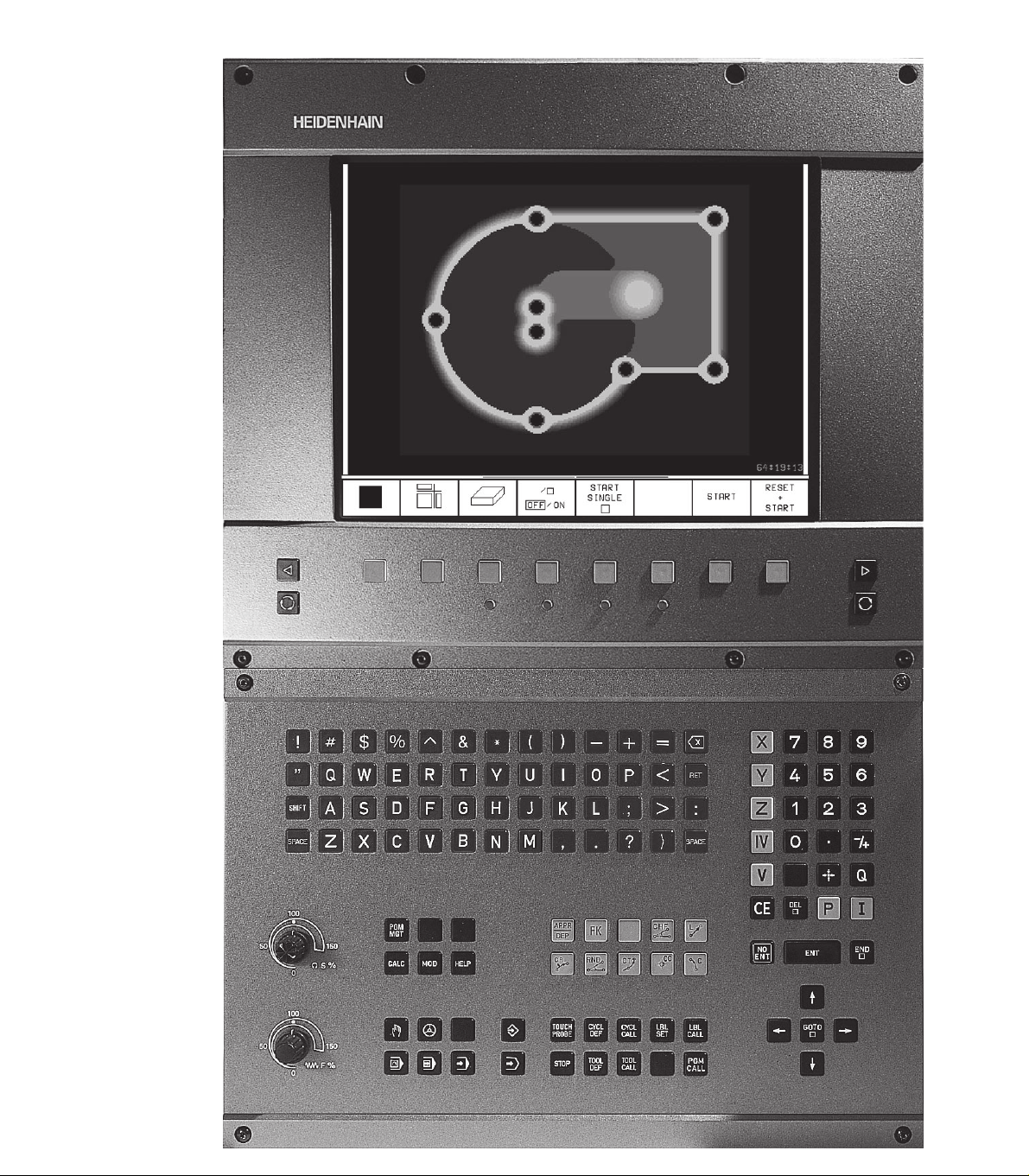
1.2 Visual Display Unit and Keyboard
Visual display unit
The TNC is available with either a color CRT screen (BC 120) or a
TFT flat panel display (BF 120. The figures at right show the keys
and controls on the BC 120 (upper right) and the BF 120 (middle
right).
Header
When the TNC is on, the selected operating modes are shown
in the screen header.
Soft keys
In the footer the TNC indicates additional functions in a soft-key
row. You can select these functions by pressing the keys
immediately below them
soft-key row indicate the number of soft-key rows that can be
called with the black arrow keys to the right and left. The line
representing the active soft-key row is highlighted.
Soft key selector keys
Switching the soft-key rows
Setting the screen layout
Shift key for switchover between machining and programming
modes
Keys on BC 120 only
Screen demagnetization;
Exit main menu for screen settings
Select main menu for screen settings;
In the main menu: Move highlight downward
In the submenu: Reduce value
In the main menu: Move highlight upward
In the submenu: Increase value
In the main menu: Select submenu
10
In the submenu: Exit submenu
See next page for the screen settings.
. The lines immediately above the
Move picture to the left or downward
Move picture to the right or upward
10
1.2 Visual Display Unit and Keyboard
3HEIDENHAIN TNC 410
Page 17
Main menu dialog Function
BRIGHTNESS Adjust brightness
CONTRAST Adjust contrast
H-POSITION Adjust horizontal position
H-SIZE Adjust picture width
V-POSITION Adjust vertical position
V-SIZE Adjust picture height
SIDE-PIN Correct barrel-shaped distortion
TRAPEZOID Correct trapezoidal distortion
ROTATION Correct tilting
COLOR TEMP Adjust color temperature
R-GAIN Adjust strength of red color
B-GAIN Adjust strength of blue color
RECALL No function
The BC 120 is sensitive to magnetic and electromagnetic noise, which
can distort the position and geometry of the picture. Alternating fields
can cause the picture to shift periodically or to become distorted.
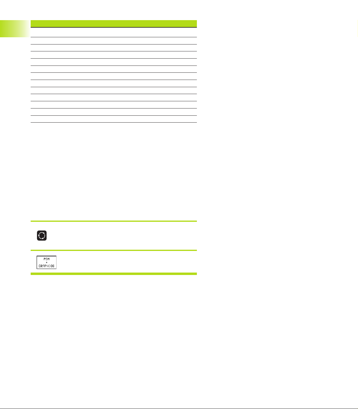
Screen layout
You select the screen layout yourself: In the PROGRAMMING AND
1.2 Visual Display Unit and Keyboard
EDITING mode of operation, for example, you can have the TNC show
program blocks in the left window while the right window displays
programming graphics. You could also display help graphics for cycle
definition in the right window instead, or display only program blocks
in one large window. The available screen windows depend on the
selected operating mode.
To change the screen layout:
Press the SPLIT SCREEN key: The soft-key row
shows the available layout options.
<
Select the desired screen layout.
4
1 Introduction
Page 18
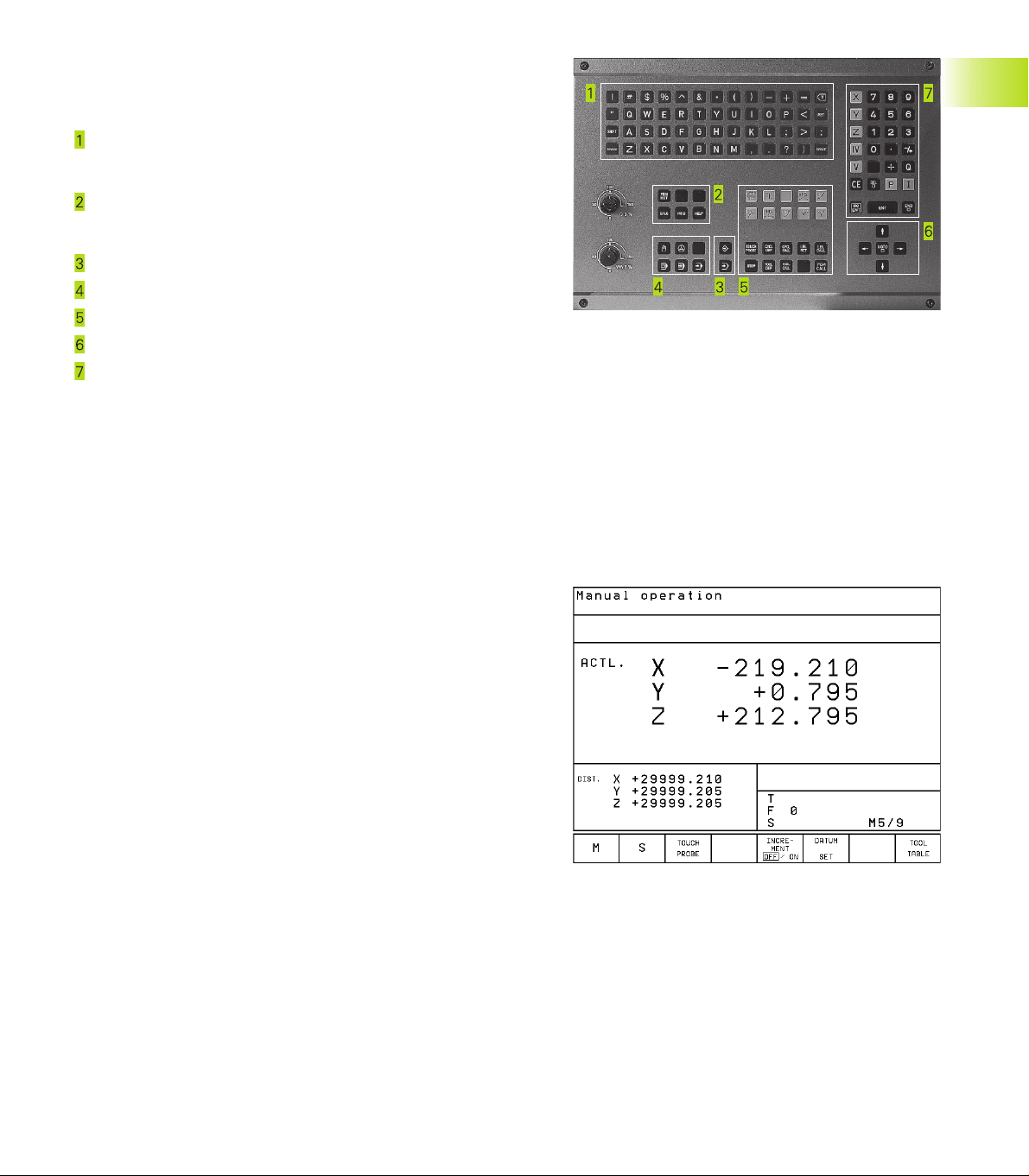
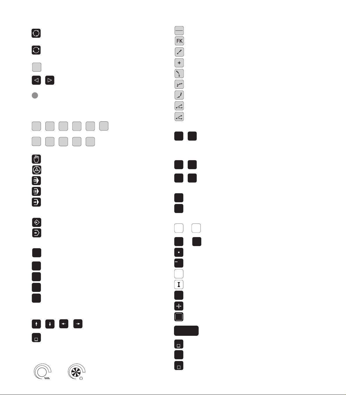
Keyboard
The figure at right shows the keys of the keyboard grouped according to their functions:
Alphanumeric keyboard
for entering texts and file names, as well as for programming in
ISO format
File management,
MOD functions,
HELP functions
Programming modes
Machine operating modes
Initiation of programming dialog
Arrow keys and GOTO jump command
Numerical input and axis selection
The functions of the individual keys are described in the foldout of the
front cover. Machine panel buttons, e.g. NC START, are described in
the manual for your machine tool.
1.3 Modes of Operation
The TNC offers the following modes of operation for the various
functions and working steps that you need to machine a workpiece:
1.3 Modes of Operation
Manual Operation and Electronic
The Manual Operation mode is required for setting up the machine
tool. In this operating mode, you can position the machine axes
manually or by increments and set the datums.
The Electronic Handwheel mode of operation allows you to move the
machine axes manually with the HR electronic handwheel.
Soft keys for selecting the screen layout
The same selection is available as in the Positioning with MDI mode.
The TNC always shows the positions at left in the divided screen.
5HEIDENHAIN TNC 410
Page 19
Positioning with Manual Data Input (MDI)
This mode of operation is used for programming simple traversing
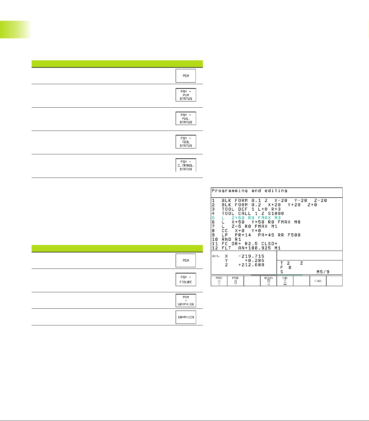
movements, such as for face milling or pre-positioning.
Soft keys for selecting the screen layout
Screen windows Soft key
Program blocks
Left: program, right: general program
information
Left: program, right: positions and
1.3 Modes of Operation
coordinates
Left: program, right: information on
tools
Left: Program, right: coordinate
transformations
Programming and Editing
In this mode of operation you can write your part programs. The FK
free programming feature, the various cycles and the Q parameter
functions help you with programming and add necessary
information. If desired, you can have the programming graphics
show the individual steps.
Soft keys for selecting the screen layout
Screen windows Soft key
Program blocks
Left: program, right: help graphics for cycle
programming
Left: program blocks, right: programming graphics
Interactive Programming Graphics
6
1 Introduction
Page 20
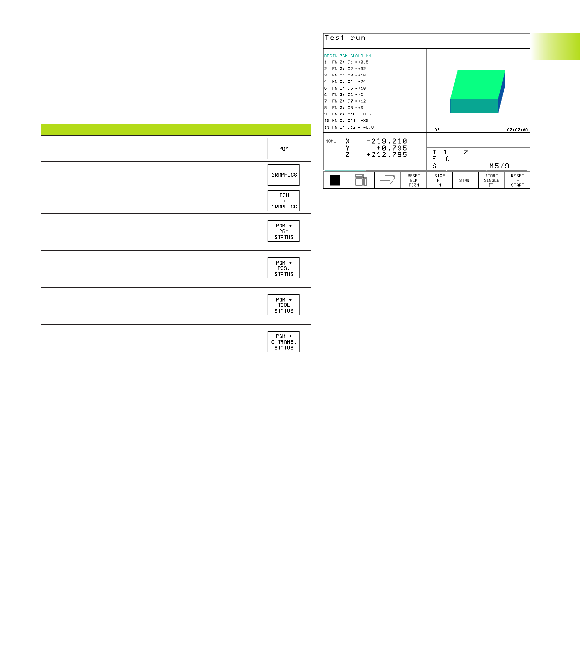
Test run
In the Test Run mode of operation, the TNC checks programs and
program sections for errors, such as geometrical incompatibilities,
missing or incorrect data within the program or violations of the
work space. This simulation is supported graphically in different
display modes.
Soft keys for selecting the screen layout
Screen windows Soft key
Program blocks
Test run graphics
Left: program, right: test run graphics
Left: program, right: general program
information
Left: program, right: positions and
coordinates
Left: program, right: information on
tools
1.3 Modes of Operation
Left: Program, right: coordinate
transformations
7HEIDENHAIN TNC 410
Page 21
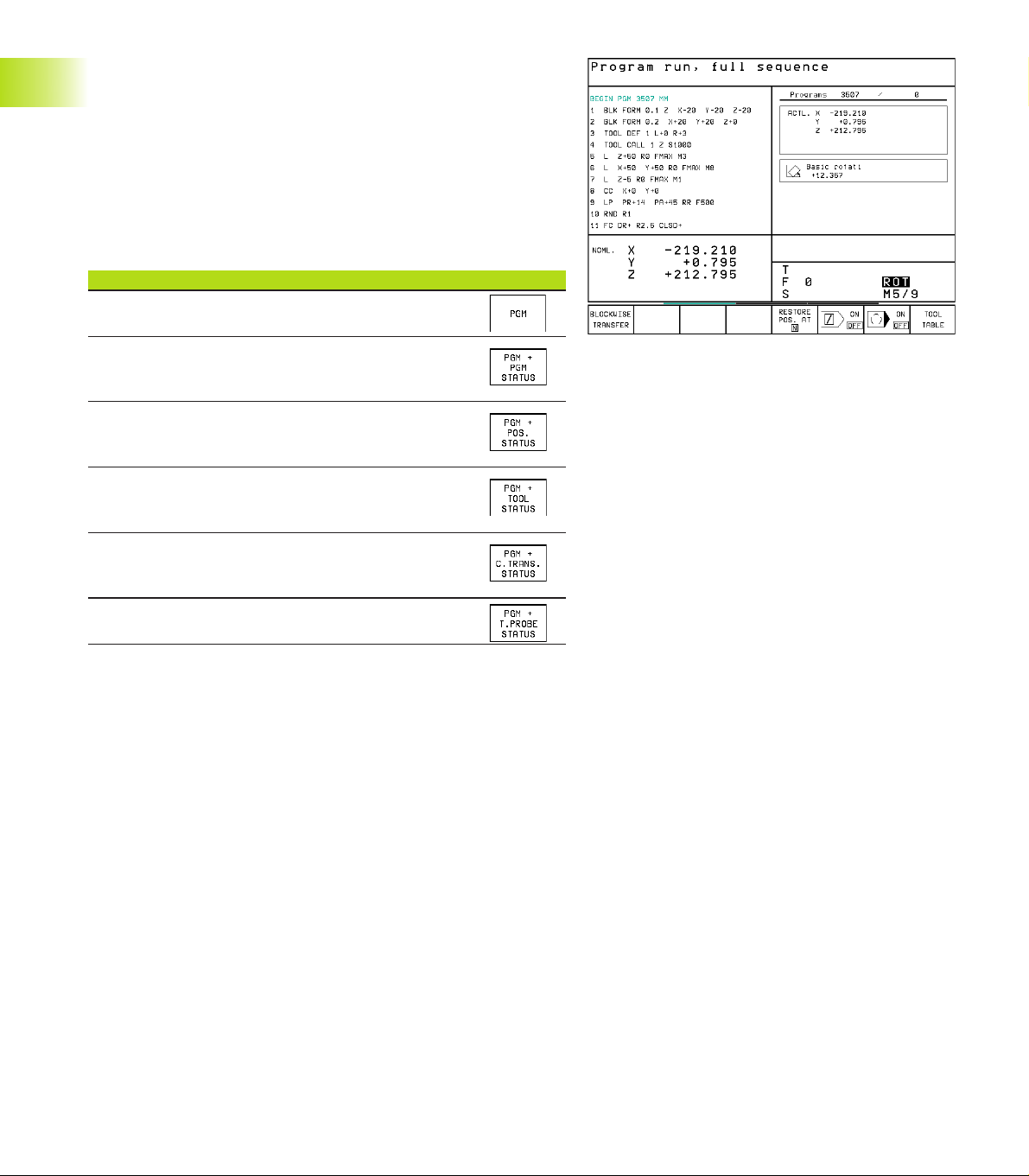
Program Run, Full Sequence and
Program Run, Single Block
In the Program Run, Full Sequence mode of operation the TNC
executes a part program continuously to its end or to a manual or
programmed stop. You can resume program run after an
interruption.
In the Program Run, Single Block mode of operation you execute
each block separately by pressing the machine START button.
Soft keys for selecting the screen layout
Screen windows Soft key
Program blocks
1.3 Modes of Operation
Left: program, right: general program
information
Left: program, right: positions and
coordinates
Left: program, right: information on
tools
Left: Program, right: coordinate
transformations
Left: program, right: tool measurement
8
1 Introduction
Page 22
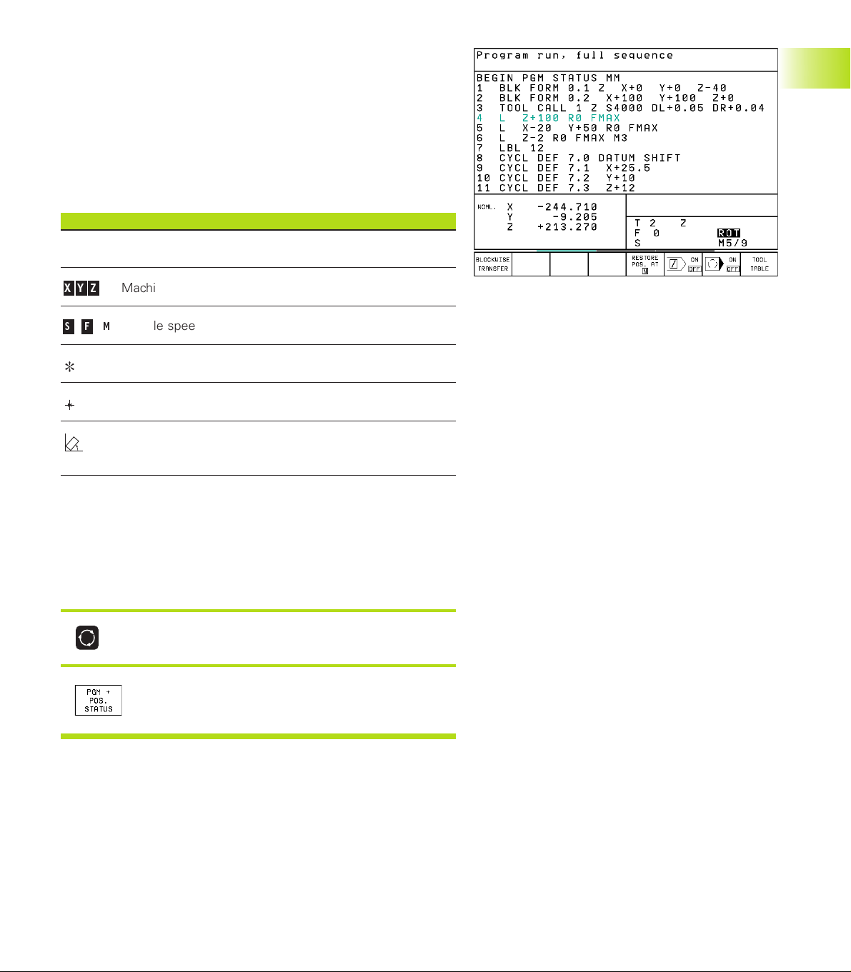
1.4 Status Displays
“General” status displays
The status display informs you of the current state of the machine
tool. It is displayed automatically in all modes of operation:
In the Manual mode,Electronic Handwheel mode, and Positioning
with MDI mode the position display appears in the large window.
Information in the status display
Symbol Meaning
ACTL. Actual or nominal coordinates of the current position
X Y Z
S F M
Machine axes
Spindle speed S, feed rate F and active M functions
Program run started
Axis locked
Axes are moving
under a basic rotation.
Additional status displays
The additional status displays contain detailed information on the
program run. They can be called in all operating modes, except in
the Programming and Editing mode of operation.
To switch on the additional status display:
1.4 Status Displays
Call the soft-key row for screen layout.
<
Select the layout option for the additional status
display, e.g. positions and coordinates.
9HEIDENHAIN TNC 410
Page 23
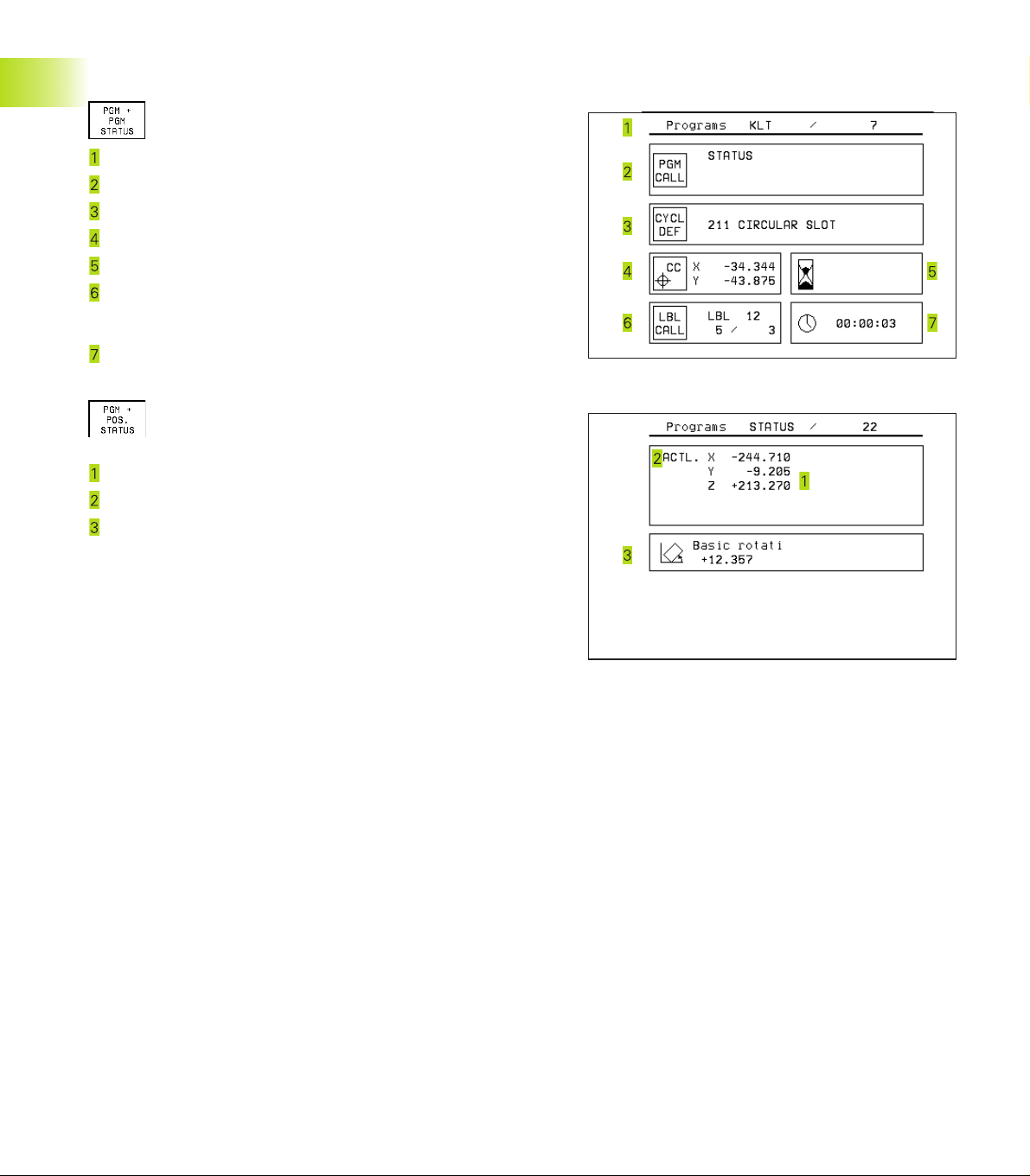
You can also choose between the following additional status
displays:
General program information
Name of main program
Active programs
Active machining cycle
Circle center CC (pole)
1.4 Status Displays
Dwell time counter
Active program section repeats/Counter for current
program section repeat
(5/3: 5 repetitions programmed, 3 remaining to be run)
Operating time
Positions and coordinates
Position display
Type of position display, e.g. actual positions
Angle of a basic rotation
10
1 Introduction
Page 24
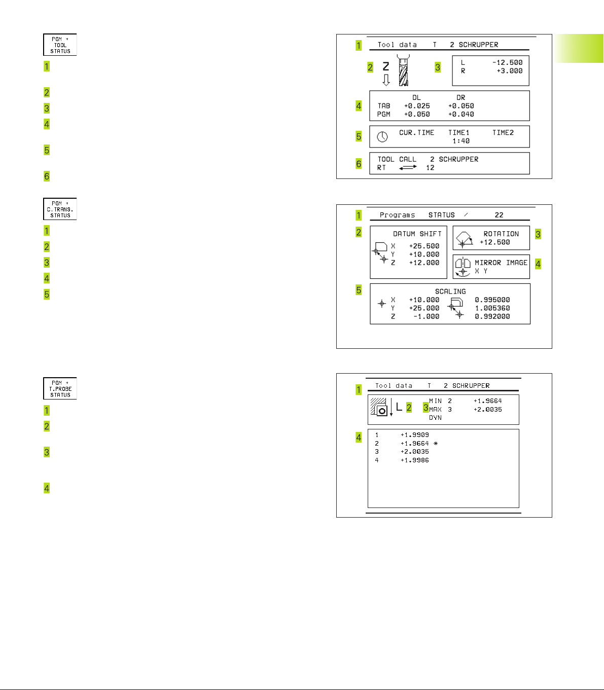
Information on tools
T: Tool number and name
RT: Number and name of a replacement tool
Tool axis
Tool length and radii
Oversizes (delta values) from TOOL CALL (PGM) and the tool
table (TAB)
Tool life, maximum tool life (TIME 1) and maximum tool life for
TOOL CALL (TIME 2)
Display of the active tool and the (next) replacement tool
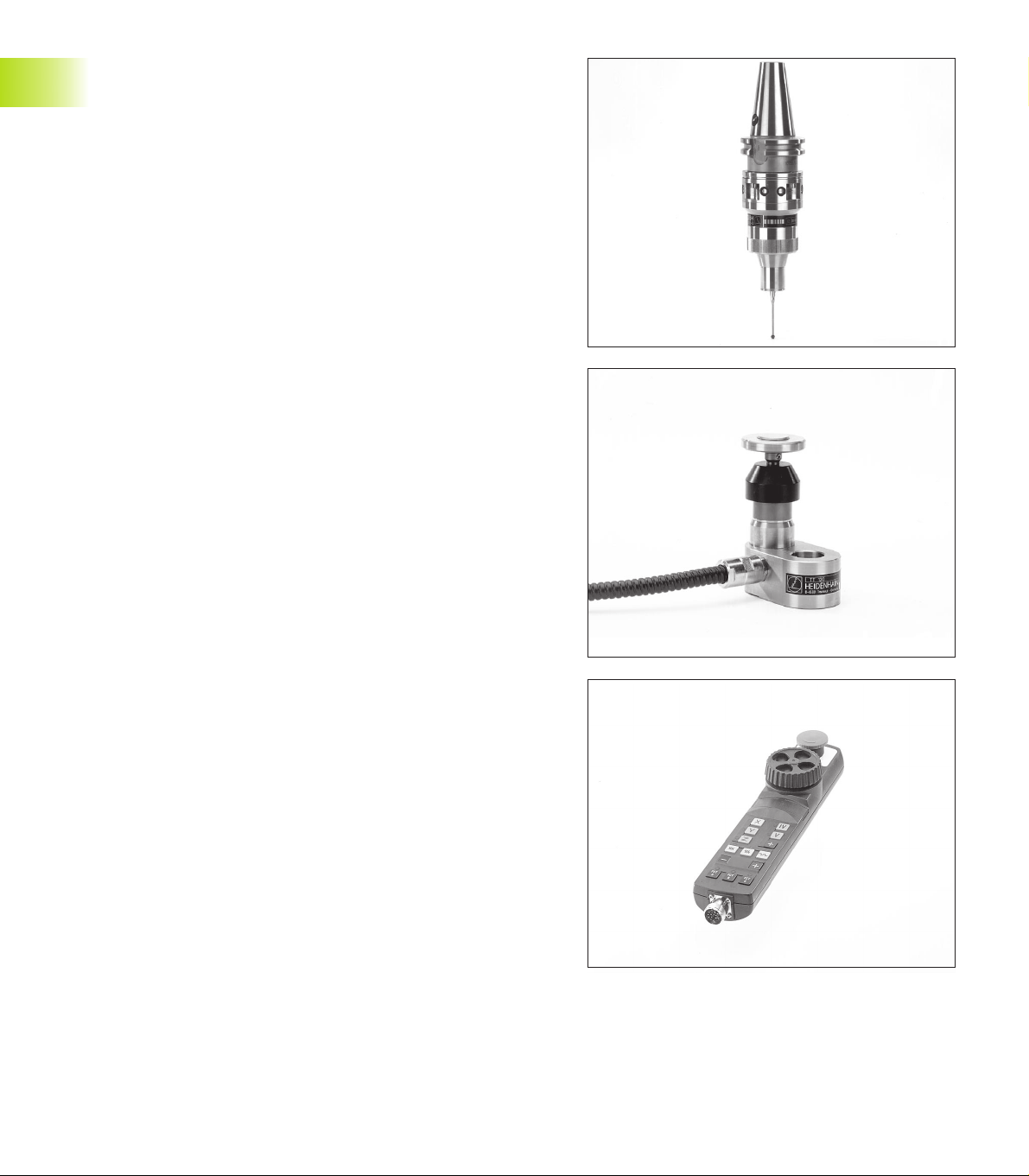
Coordinate transformations
Name of main program
Active datum shift (Cycle 7)
Active rotation angle (Cycle 10)
Mirrored axes (Cycle 8)
Active scaling factor (Cycle 11 or Cycle 26)
For further information, refer to section 8.8 “Coordinate Transformation Cycles.”
4
1.4 Status Displays
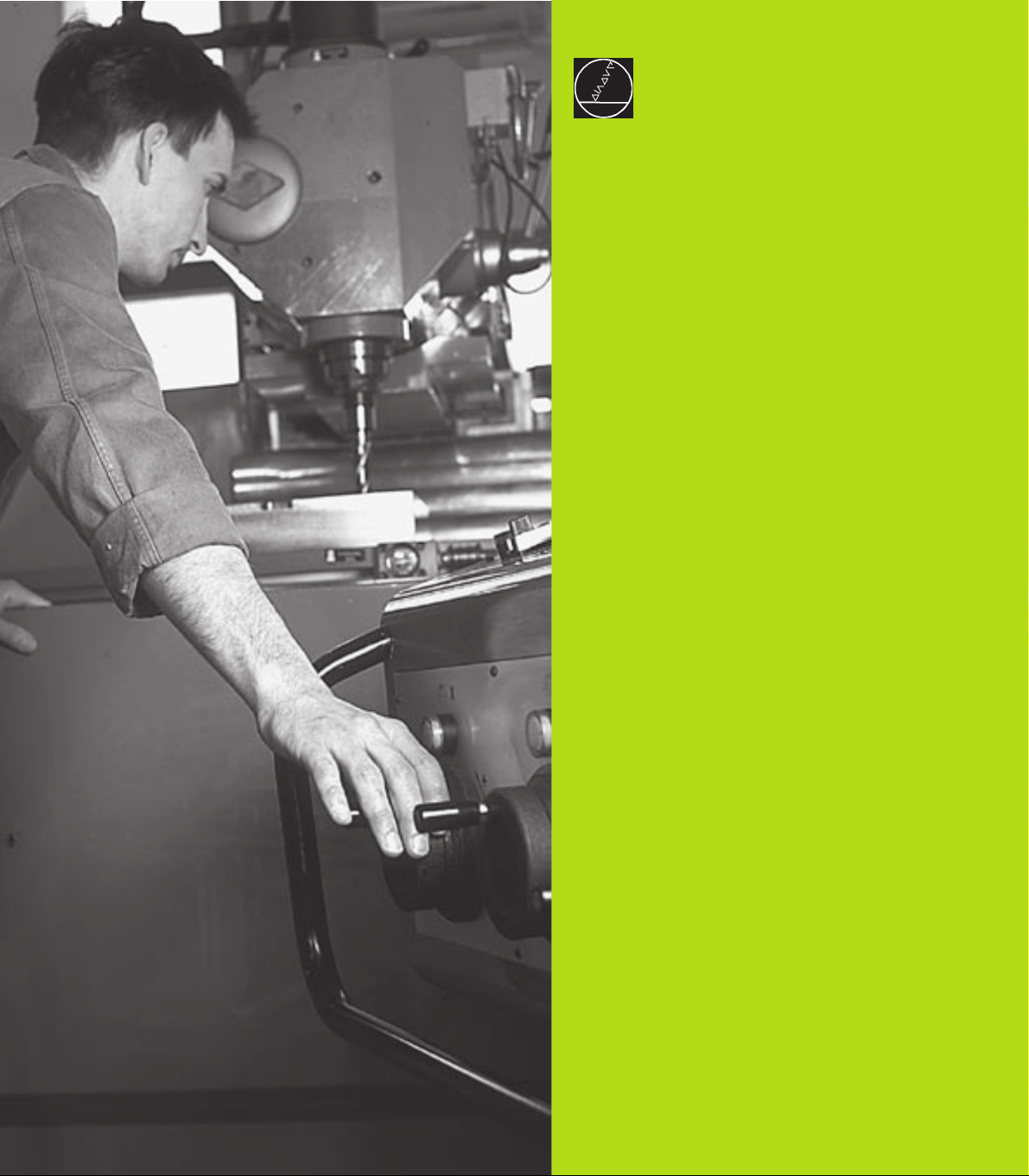
Tool measurement
Number of the tool to be measured
Display whether the tool radius or the tool length is being
measured
MIN and MAX values of the individual cutting edges and the
result of measuring the rotating tool (DYN = dynamic
measurement)
Cutting edge number with the corresponding measured value.
If the measured value is followed by an asterisk, the allowable
tolerance in the tool table was exceeded.
11HEIDENHAIN TNC 410
Page 25
1.5 Accessories: HEIDENHAIN 3-D
Touch Probes and Electronic
Handwheels
3-D Touch Probes
With the various HEIDENHAIN 3-D touch probe systems you can:
■ Automatically align workpieces
■ Quickly and precisely set datums
■ Measure the workpiece during program run
■ Digitize 3-D surfaces (option), and
■ Measure and inspect tools
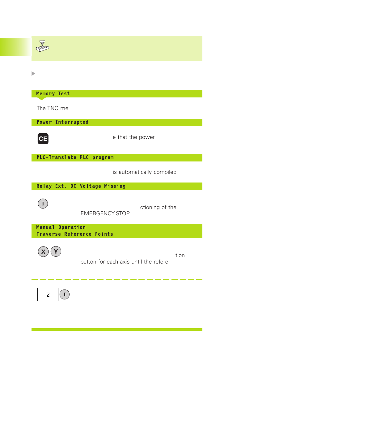
TS 220 and TS 630 touch trigger probes
These touch probes are particularly effective for automatic
workpiece alignment, datum setting, workpiece measurement and
for digitizing. The TS 220 transmits the triggering signals to the TNC
via cable and is a cost-effective alternative for applications where
digitizing is not frequently required.
The TS 630 features infrared transmission of the triggering signal to
the TNC. This makes it highly convenient for use on machines with
automatic tool changers.
Principle of operation: HEIDENHAIN triggering touch probes feature
a wear resisting optical switch that generates an electrical signal as
soon as the stylus is deflected. This signal is transmitted to the
TNC, which stores the current position of the stylus as an actual
value.
During digitizing the TNC generates a program containing straight
line blocks in HEIDENHAIN format from a series of measured
position data. You can then output the program to a PC for further
processing with the SUSA evaluation software. This evaluation
software enables you to calculate male/female transformations or
correct the program to account for special tool shapes and radii that
differ from the shape of the stylus tip. If the tool has the same
radius as the stylus tip you can run these programs immediately.
TT 120 tool touch probe for tool measurement
The TT 120 is a triggering 3-D touch probe for tool measurement
and inspection. Your TNC provides three cycles for this touch probe
with which you can measure the tool length and radius
automatically— either with the spindle rotating or stopped.
The TT 120 features a particularly rugged design and a high degree
of protection, which make it insensitive to coolants and swarf. The
triggering signal is generated by a wear-resistant and highly reliable
optical switch.
1.5 Accessories: HEIDENHAIN 3-D Touch Probes and Electronic Handwheels
HR electronic handwheels
Electronic handwheels facilitate moving the axis slides precisely by
hand. A wide range of traverses per handwheel revolution is
available. Apart from the HR 130 and HR 150 integral handwheels,
HEIDENHAIN also offers the HR 410 portable handwheel.
12
1 Introduction
Page 26
2
Manual Operation and Setup
Page 27
2.1 Switch-On
Switch-on and traversing the reference points can vary
depending on the individual machine tool. Refer to your
machine manual.
Switch on the power supply for control and machine.
2.1 Switch-On
The TNC automatically initiates the following dialog
Memory Test
<
The TNC memory is automatically checked.
Power Interrupted
<
TNC message that the power was interrupted
— clear the message.
PLC-Translate PLC program
<
The PLC program of the TNC is automatically compiled.
Relay Ext. DC Voltage Missing
<
Switch on the control voltage.
The TNC checks the functioning of the
EMERGENCY STOP circuit.
Manual Operation
Traverse Reference Points
<
Cross the reference points in any sequence:
Press and hold the machine axis direction
button for each axis until the reference point has
been traversed, or
Cross the reference points with several axes at
the same time: Use soft keys to select the axes
(axes are then shown highlighted on the
screen), and then press the machine START
button.
The TNC is now ready for operation in the
Manual Operation mode.
14
2 Manual Operation and Setup
Page 28
2.2 Moving the Machine Axes
Traversing with the machine axis direction buttons is a
machine-dependent function. Your machine manual
provides more detailed information.
To traverse with the machine axis direction buttons:
Select the Manual Operation mode.
<
Press the machine axis direction button and
hold it as long as you wish the axis to move.
...or move the axis continuously:
and Press and hold the machine axis direction
button, then press the machine START button:
The axis continues to move after you release
the keys.
2.2 Moving the Machine Axes
To stop the axis, press the machine STOP
button.
You can move several axes at a time with these two methods.
15HEIDENHAIN TNC 410
Page 29
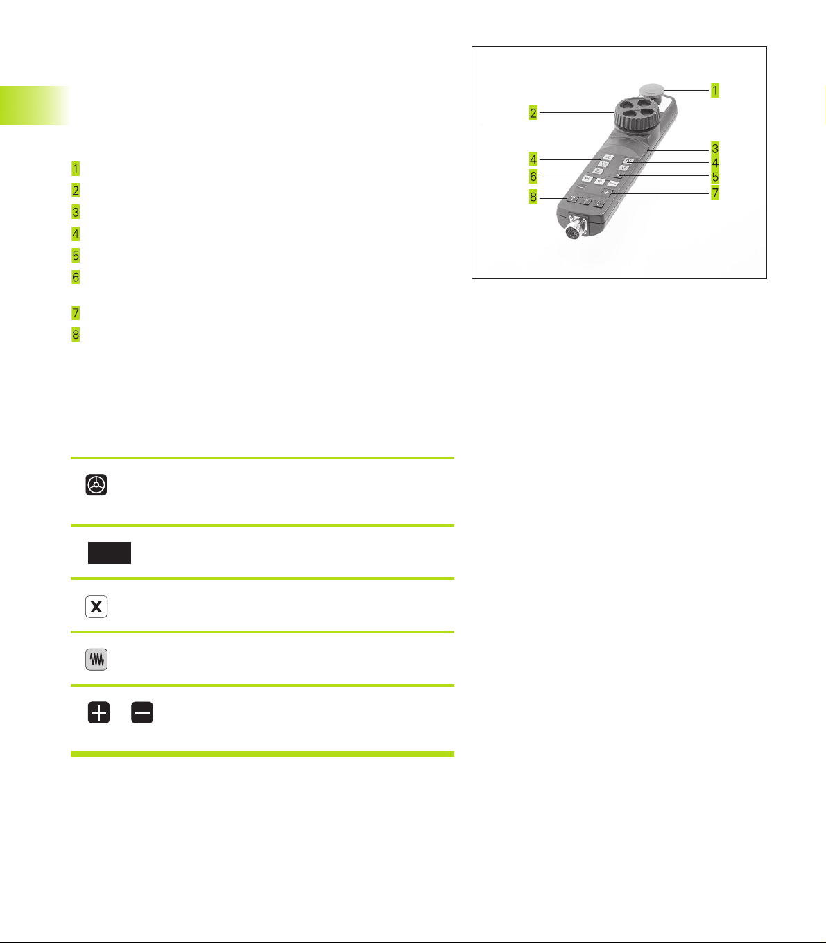
Traversing with the HR 410 electronic handwheel
The portable HR 410 handwheel is equipped with two permissive
buttons. The permissive buttons are located below the star grip.
You can only move the machine axes when an permissive button is
depressed (machine-dependent function).
The HR 410 handwheel features the following operating elements:
EMERGENCY STOP
Handwheel
Permissive buttons
Axis address keys
Actual-position-capture key
Keys for defining the feed rate (slow, medium, fast; the feed
rates are set by the machine tool builder)
2.2 Moving the Machine Axes
Direction in which the TNC moves the selected axis
Machine function
(set by the machine tool builder)
The red indicators show the axis and feed rate you have selected.
It is also possible to move the machine axes with the handwheel
during a program run.
To move an axis:
Select the Electronic Handwheel mode of
operation
Press and hold the permissive button
<
Select the axis.
<
Select the feed rate.
<
or Move the active axis in the positive or
negative direction.
16
2 Manual Operation and Setup
Page 30
16
X
Z
8
8
8
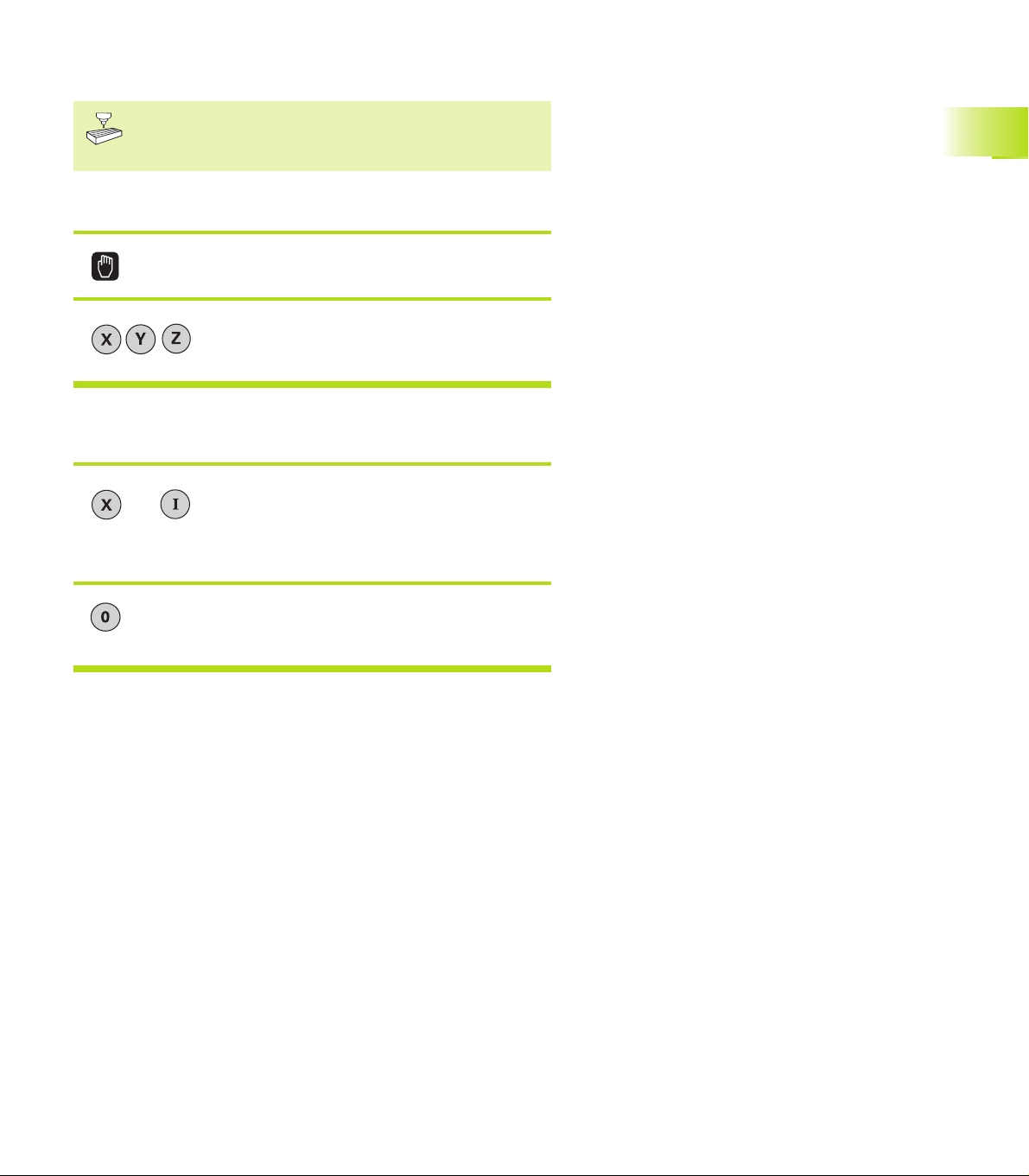
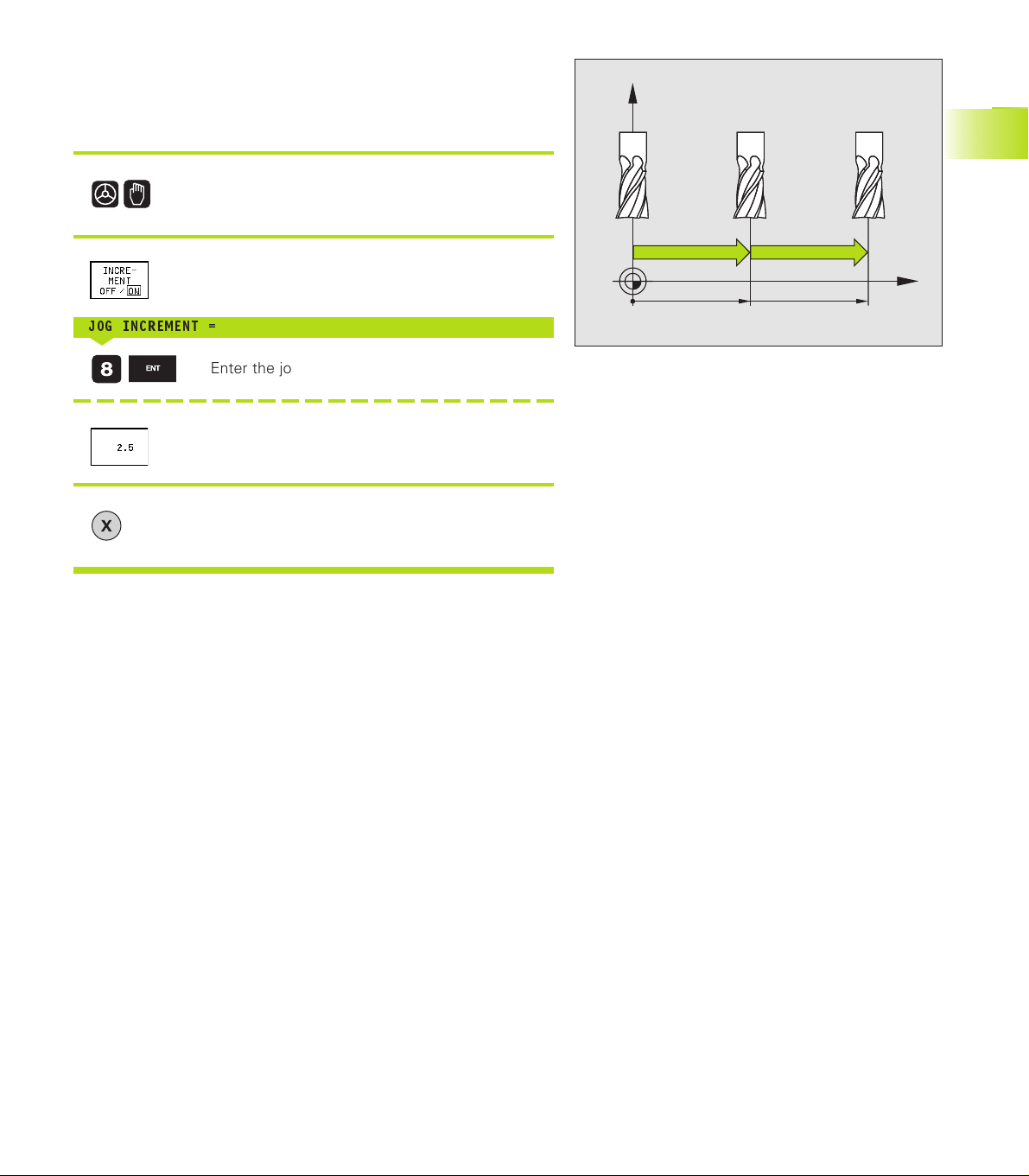
Incremental jog positioning
With incremental jog positioning you can move a machine axis by a
preset distance each time you press the corresponding machine
axis direction button.
Select the Electronic Handwheel or Manual
mode of operation.
<
Select incremental jog positioning, set the soft
key to On.
JOG INCREMENT =
<
Enter the jog increment in mm, e.g. 8 mm, or
Enter the jog increment via soft key (preset softkey values).
<
Press the machine axis direction button as often
as desired.
2.2 Moving the Machine Axes
17HEIDENHAIN TNC 410
Page 31

2.3 Spindle Speed S, Feed Rate F and
Miscellaneous Functions M
In the operating modes Manual and Electronic Handwheel, enter
the spindle speed S and the miscellaneous function M using soft
keys. The miscellaneous functions are described in Chapter 7
”Programming: Miscellaneous Functions.” The feed rate is defined
in a machine parameter and can be changed only with the override
knobs (see next page).
Entering values
Example: Enter the spindle speed S
To enter the spindle speed, press the S soft key.
Spindle speed S=
<
1000 Enter the desired spindle speed,
and confirm your entry with the machine START
button.
The spindle speed S with the entered rpm is started with a
miscellaneous function.
Proceed in the same way to enter the miscellaneous functions M.
Changing the spindle speed S and feed rate F
With the override knobs you can vary the spindle speed S and feed
rate F from 0% to 150% of the set value.
The knob for spindle speed override is effective only on
machines with an infinitely variable spindle drive.
The machine tool builder determines which
miscellaneous functions M are available on your TNC and
what effects they have.
2.3 Spindle Speed S, Feed Rate F and Miscellaneous Functions M
18
2 Manual Operation and Setup
Page 32

2.4 Setting the Datum
(Without a 3-D Touch Probe)
You fix a datum by setting the TNC position display to the
coordinates of a known position on the workpiece.
To prepare the TNC:
ú Clamp and align the workpiece.
ú Insert the zero tool with known radius into the spindle.
ú Ensure that the TNC is showing the actual position values.
Y
Z
X
Y
X
Set the datum
Fragile workpiece? If the workpiece surface must not be scratched,
you can lay a metal shim of know thickness
tool axis datum value that is larger than the desired datum by the
d
.
value
Select the Manual Operation mode.
<
Move the tool slowly until it touches the
workpiece surface.
<
Select the axis.
Datum Set
<
Repeat the process for the remaining axes.
If you are using a preset tool, set the display of the tool axis to the
length L of the tool or enter the sum Z=L+d.
ÿÿÿ
Zero tool in spindle axis: Set the display to a
known workpiece position (here, 0) or enter the
d
thickness
the tool radius.
of the shim. In the tool axis, offset
d
on it. Then enter a
2.4 Setting the Datum
19HEIDENHAIN TNC 410
Page 33

Page 34

3
Positioning with Manual Data
Input (MDI)
Page 35

3.1 Programming and Executing
Simple Positioning Blocks
The operating mode Positioning with Manual Data Input is
particularly convenient for simple machining operations or prepositioning of the tool. It enables you to write a short program in
HEIDENHAIN conversational programming or in ISO format, and
execute it immediately. You can also call TNC cycles. The program is
stored in the file $MDI. In the operating mode Positioning with MDI,
the additional status displays can also be activated.
Select the Positioning with MDI mode of
operation. Program the file $MDI as you wish.
To start program run, press the machine START
button.
Limitations:
The following functions are not available:
- - Tool radius compensation
- FK free contour programming
- Programming graphics and program-run graphics
- The programmable probing functions
- Subprograms, Program section repetitions
- The path functions CT, CR, RND and CHF
- PGM CALL
Example 1
A hole with a depth of 20 mm is to be drilled into a single
workpiece. After clamping and aligning the workpiece and setting
the datum, you can program and execute the drilling operation in a
few lines.
3.1 Programming and Executing Simple Positioning Blocks
First you pre-position the tool in L blocks (straight-line blocks) to the
hole center coordinates at a setup clearance of 5 mm above the
workpiece surface. Then drill the hole with Cycle 1 PECKING.
50
Z
Y
X
50
0 BEGIN PGM $MDI MM
1 TOOL DEF 1 L+0 R+5
2 TOOL CALL 1 Z S2000
3 L Z+200 R0 FMAX
4 L X+50 Y+50 R0 FMAX M3
5 L Z+5 F2000
22
Define tool: zero tool, radius 5
Call tool: tool axis Z
Spindle speed 2000 rpm
Retract tool (FMAX = rapid traverse)
Move the tool at FMAX to a position above the borehole, spindle on Position tool to 5 mm above hole
3 Positioning with Manual Data Input (MDI)
Page 36

6 CYCL DEF 1.0 PECKING
7 CYCL DEF 1.1 SET UP 5
8 CYCL DEF 1.2 DEPTH -20
9 CYCL DEF 1.3 PECKG 10
10 CYCL DEF 1.4 DWELL 0.5
11 CYCL DEF 1.5 F250
12 CYCL CALL
13 L Z+200 R0 FMAX M2
14 END PGM $MDI MM
The straight-line function is described in section 6.4 “Path Contours
— Cartesian Coordinates,” the PECKING cycle in section 8.3 “Drilling Cycles.”
Example 2
Correcting workpiece misalignment on machines with rotary tables
Use the 3-D touch probe to rotate the coordinate system.
See ”12.1 Touch probe cycles in the Manual and Electronic
Handwheel Mode” section ”Compensating workpiece
misalignment.”
<
Write down the Rotation Angle and cancel the Basic Rotation.
Define PECKING cycle:
Setup clearance of the tool above the hole
Total hole depth (Algebraic sign=working direction)
Depth of each infeed before retraction
Dwell time in seconds at the hole bottom
Feed rate for pecking
Call PECKING cycle
Retract tool
End of program
<
Select operating mode: Positioning with MDI.
<
Select the axis of the rotary table, enter the
rotation angle you wrote down previously and
set the feed rate.
For example: L C+2.561 F50
<
Conclude entry.
<
Press the machine START button: The rotation of
the table corrects the misalignment. After the
NC start the highlight is moved onto the next
block.
3.1 Programming and Executing Simple Positioning Blocks
23HEIDENHAIN TNC 410
Page 37

Protecting and erasing programs in $MDI
The $MDI file is generally intended for short programs that are only
needed temporarily. Nevertheless, you can store a program, if
necessary, by proceeding as described below:
Select operating mode: Programming
and Editing
<
To call the file manager, press the PGM MGT
key (program management).
<
Move the highlight to the $MDI file.
<
Select „Copy file“: Press the COPY soft key
Target file =
<
BOREHOLE
<
Enter the name under which you want to save
the current contents of the $MDI file.
Copy the file.
<
To close the file manager, press the END soft
key.
Erasing the contents of the $MDI file is done in a similar way:
3.1 Programming and Executing Simple Positioning Blocks
Instead of copying the contents, however, you erase them with the
DELETE soft key. The next time you select the operating mode
Positioning with MDI, the TNC will display an empty $MDI file.
If you wish to switch between conversational and ISO
programming with the MOD function, you need to
delete the current file $MDI.*, and then select again the
Positioning with MDI operating mode.
For further information, refer to section 4.2 “File Management.”
24
3 Positioning with Manual Data Input (MDI)
Page 38

4
Programming:
Fundamentals of NC,
File Management,
Programming Aids
Page 39

4.1 Fundamentals of NC
Position encoders and reference marks
The machine axes are equipped with position encoders that
register the positions of the machine table or tool. When a machine
axis moves, the corresponding position encoder generates an
electrical signal. The TNC evaluates this signal and calculates the
precise actual position of the machine axis.
If there is an interruption of power, the calculated position will no
longer correspond to the actual position of the machine slide. The
TNC can re-establish this relationship with the aid of reference
marks when power is returned. The scales of the position encoders
contain one or more reference marks that transmit a signal to the
TNC when they are crossed over. From the signal the TNC identifies
4.1 Fundamentals of NC
that position as the machine-axis reference point and can reestablish the assignment of displayed positions to machine axis
positions.
Linear encoders are generally used for linear axes. Rotary tables
and tilt axes have angle encoders. If the position encoders feature
distance-coded reference marks, you only need to move each axis a
maximum of 20 mm (0.8 in.) for linear encoders, and 20° for angle
encoders, to re-establish the assignment of the displayed positions
to machine axis positions.
Z
Y
X
X
MP
X (Z,Y)
26
4 Programming: Fundamentals of NC, File Management, Programming Aids
Page 40

Reference system
A reference system is required to define positions in a plane or in
space. The position data are always referenced to a predetermined
point and are described through coordinates.
The Cartesian coordinate system (a rectangular coordinate system)
is based on three coordinate axes X, Y and Z. The axes are mutually
perpendicular and intersect at one point called the datum. A
coordinate identifies the distance from the datum in one of these
directions. A position in a plane is thus described through two
coordinates, and a position in space through three coordinates.
Coordinates that are referenced to the datum are referred to as
absolute coordinates. Relative coordinates are referenced to any
other known position (datum) you define within the coordinate
system. Relative coordinate values are also referred to as
incremental coordinate values.
Reference systems on milling machines
When using a milling machine, you orient tool movements to the
Cartesian coordinate system. The illustration at right shows how
the Cartesian coordinate system describes the machine axes. The
figure at right illustrates the “right-hand rule” for remembering the
three axis directions: the middle finger is pointing in the positive
direction of the tool axis from the workpiece toward the tool (the Z
axis), the thumb is pointing in the positive X direction, and the index
finger in the positive Y direction.
The TNC 410 can control up to 4 axes. The axes U, V and W are
secondary linear axes parallel to the main axes X, Y and Z,
respectively. Rotary axes are designated as A, B and C. The
illustration shows the assignment of secondary axes and rotary
axes to the main axes.
+Y
Z
Y
X
4.1 Fundamentals of NC
+Z
+Y
+X
+Z
+X
V+
Z
Y
W+
C+
B+
A+
X
U+
27HEIDENHAIN TNC 410
Page 41

Polar coordinates
If the production drawing is dimensioned in Cartesian coordinates,
you also write the part program using Cartesian coordinates. For
parts containing circular arcs or angles it is often simpler to give the
dimensions in polar coordinates.
While the Cartesian coordinates X, Y and Z are three-dimensional
and can describe points in space, polar coordinates are twodimensional and describe points in a plane. Polar coordinates have
their datum at a circle center (CC), or pole. A position in a plane can
be clearly defined by the
■ Polar Radius, the distance from the circle center CC to the
position, and the
■ Polar Angle, the size of the angle between the reference axis and
the line that connects the circle center CC with the position.
4.1 Fundamentals of NC
See figure to the lower right.
Setting the pole and the angle reference axis
The pole is set by entering two Cartesian coordinates in one of the
three planes. These coordinates also set the reference axis for the
polar angle PA.
Coordinates of the pole (plane) Reference axis of the angle
XY +X
YZ +Y
ZX +Z
10
Z
Y
PR
PA
2
PA
3
PR
CC
PA
PR
1
0°
X
30
Y
Z
Y
X
Z
Y
28
X
X
4 Programming: Fundamentals of NC, File Management, Programming Aids
Page 42

Absolute and relative workpiece positions
Absolute workpiece positions
Absolute coordinates are position coordinates that are referenced
to the datum of the coordinate system (origin). Each position on the
workpiece is uniquely defined by its absolute coordinates.
Example 1: Holes dimensioned in absolute coordinates
Hole
X=10 mm X=30 mm X=50 mm
Y=10 mm Y=20 mm Y=30 mm
Hole Hole
Y
30
20
10
Relative workpiece positions
Relative coordinates are referenced to the last programmed
nominal position of the tool, which serves as the relative (imaginary)
datum. When you write a part program in incremental coordinates,
you thus program the tool to move by the distance between the
previous and the subsequent nominal positions. Incremental
coordinates are therefore also referred to as chain dimensions.
To program a position in incremental coordinates, enter the prefix
“I” before the axis.
Example 2: Holes dimensioned in relative coordinates
Absolute coordinates of hole
:
X= 10 mm
Y= 10 mm
referenced to hole Hole referenced to hole
Hole
IX= 20 mm IX= 20 mm
IY= 10 mm IY= 10 mm
Absolute and incremental polar coordinates
Absolute polar coordinates always refer to the pole and the
reference axis.
Incremental polar coordinates always refer to the last programmed
nominal position of the tool.
10
10 10
3010
50
4.1 Fundamentals of NC
Y
X
20
10
20
Y
X
10
PR
+IPA
+IPR
PR
30
+IPA
CC
PA
PR
0°
X
29HEIDENHAIN TNC 410
Page 43

Selecting the datum
A production drawing identifies a certain point on the workpiecee
— usually a cornerr — as the absolute datum. Before setting the
datum, you align the workpiece with the machine axes and move
the tool in each axis to a known position relative to the workpiece.
You then set the TNC display to either zero or a predetermined
position value. This establishes the reference system for the
workpiece, which will be used for the TNC display and your part
program.
If the production drawing is dimensioned in relative coordinates,
simply use the coordinate transformation cycles. For further
information, refer to section 8.8 “Coordinate Transformation
Cycles.”
If the production drawing is not dimensioned for NC, set the datum
4.1 Fundamentals of NC
at a position or corner on the workpiece, which is the most suitable
for deducing the dimensions of the remaining workpiece positions.
The fastest, easiest and most accurate way of setting the datum is
by using a 3-D touch probe from HEIDENHAIN. For further
information, refer to section 12.2 “Setting the Datum with a 3-D
Touch Probe.”
Example
The workpiece drawing at right illustrates the holes
are dimensioned to an absolute datum with the coordinates X=0
Y=0. The holes
absolute coordinates X=450 Y=750. By using the DATUM SHIFT
cycle you can shift the datum temporarily to the position X=450,
Y=750 and program the holes
calculations.
to are referenced to a relative datum with the
to without any further
to , which
750
320
Z
Y
X
Y
150
0
-150
0,1
±
300
0
30
325
450 900
950
4 Programming: Fundamentals of NC, File Management, Programming Aids
X
Page 44

4.2 File Management
Files in the TNC Type
Files and file management
When you write a part program on the TNC, you must first enter a
file name. The TNC then stores the program as a file with the same
name. You can also store tables as files.
File names
The name of a file can have up to 8 characters. The special
characters @, $, _, %, # and & are permitted. When you store
programs and tables as files, the TNC adds an extension to the file
name, separated by a point. This extension identifies the file type
(see table at right).
PROG20 .H
File name File type
The TNC permits only one file type per file name. You
cannot assign several file types to the same name.
The TNC can manage up to 64 files. Their total size, however, must
not exceed 256 KB.
Working with the file manager
This section informs you about the meaning of the individual
screen information, and describes how to select files and
directories. If you are not yet familiar with the TNC file manager, we
recommend that you read this section completely and test the
individual functions on your TNC.
Programs
in HEIDENHAIN conversational format .H
in ISO format .I
Tables for
Tools .T
Tool pockets .TCH
Datums .D
Points .PNT
4.2 File Management
To call the file manager
Press the PGM MGT key:
the TNC displays the file management window
The window shows you all of the files that are stored in the TNC.
Each file is shown with additional information that is illustrated in
the table on the next page.
Display Meaning
File name Name with up to 8 characters
and file type
Properties of the file:
M Program is selected
in a Program Run
operating mode
P Protect a file against
editing and erasure (Protected)
Display of long file directories Soft key
Move pagewise up through
the file directory
Move pagewise down through
the file directory
31HEIDENHAIN TNC 410
Page 45

Select a file
Call the file manager.
<
Use the arrow keys to move the highlight to the desired file:
Move the highlight up or down
Delete a file
ú Move the highlight to the file you want to delete.
ú To select the erasing function, press
the DELETE soft key.
The TNC inquires whether you really
intend to erase the file.
ú To confirm erasure press the YES soft
key.
Abort with the NO soft key if you do
not wish to erase the file.
Enter the first or more letters of the file you wish to select and then
4.2 File Management
press the GOTO key: The highlight moves to the first file that
matches these letters.
<
The selected file is opened in the operating
mode from which you have the called file
manager: Press ENT.
Copy a file
ú Move the highlight to the file you wish to copy.
ú Press the COPY soft key to select the copying
function.
ú Enter the name of the destination file and confirm your entry with
the ENT key: The TNC copies the file. The original file is retained.
Rename a file
ú Move the highlight to the file you wish to rename.
ú Select the renaming function.
ú Enter the new file name; the file type cannot be
changed.
ú To execute renaming, press the ENT key.
Protecting a file/Canceling file
protection
ú Move the highlight to the file you want to protect.
ú To enable file protection, press the
PROTECT/UNPROTECT soft key.
The file now has status P.
To cancel file protection, proceed in the same way
using the PROTECT/UNPROTECT soft key. You also
need to enter the code number 86357.
Converting an FK program into
HEIDENHAIN conversational format
ú Move the highlight to the file you want to convert.
ú To select the converting function,
press the CONVERT FK->H soft key
(2nd soft-key row).
ú Enter the name of the destination file.
ú To execute conversion, press the ENT
key.
32
4 Programming: Fundamentals of NC, File Management, Programming Aids
Page 46

Read in/read out files
ú To read in or read out files: Press the ENT soft key. The
TNC provides the functions described below.
If a file to be read in already exists in the memory of the
TNC, the TNC displays the message ”File xxx already
exists. Read in file? In this case, answer the dialog
question with YES (file is the read in) or NO (file is not
read in).
Likewise, if a file to be read out already exists on the
external device, the TNC asks whether you wish to
overwrite the external file.
Read in all files (file types: .H, .I, .T, . TCH, .D, .PNT)
ú Read in all of the files that are stored on the external
data medium.
Read in offered file
ú List all files of a certain file type.
ú For example: list all HEIDENHAIN conversational
programs. To read-in the listed program, press the YES
soft key. If you do not wish the read-in the program,
press NO.
Read out all files (file types: .H, .I, .T, . TCH, .D,
.PNT)
ú Output all files stored in the TNC to an
external device.
Display a file directory of the external device
(File types: .H, .I, .T, . TCH, .D, .PNT)
ú Display a list of files stored in the
external device. The files are displayed
pagewise. To show the next page:
press the YES soft key. To return to the
main menu: press the NO soft key.
4.2 File Management
Read in a specific file
ú Enter the file name. Confirm with the ENT key.
ú Select the file type, e.g. HEIDENHAIN dialog program.
If you with to read-in the tool table TOOL.T, press the TOOL TABLE
soft key. If you with to read-in the tool-pocket table TOOLP.TCH,
press the POCKET TABLE soft key.
Read out a specific file
ú Select the function for reading out a single file.
ú Move the highlight to the file that you wish to read
out. Press ENT or TRANSFER soft key to start the
transfer.
ú To terminate the function for reading out specific files:
press the END key.
33HEIDENHAIN TNC 410
Page 47

4.3 Creating and Writing Programs
Organization of an NC program in HEIDENHAIN
conversational format
A part program consist of a series of program blocks. The figure at
right illustrates the elements of a block.
The TNC numbers the blocks in ascending sequence.
The first block of a program is identified by “BEGIN PGM,” the
program name and the active unit of measure.
The subsequent blocks contain information on:
■ The blank form
■ Tool definitions and tool calls,
■ Feed rates and spindle speeds as well as
■ Path contours, cycles and other functions.
The last block of a program is identified by “END PGM,” the program name and the active unit of measure.
4.3 Creating and Writing Programs
Defining the blank form — BLK FORM
Immediately after initiating a new program, you define a cuboid
workpiece blank. This definition is needed for the TNC’s graphic
simulation feature. The sides of the workpiece blank lie parallel to
the X, Y and Z axes and can be up to 30 000 mm long. The blank
form is defined by two of its corner points:
■ MIN point: the smallest X, Y and Z coordinates of the blank form,
entered as absolute values.
■ MAX point: the largest X, Y and Z coordinates of the blank form,
entered as absolute or incremental values.
The TNC can display the graphic only if the short side of the BLK
FORM is longer than 1/64 of the long side.
Block:
10 L X+10 Y+5 R0 F100 M3
Path function Words
Block number
Z
Y
MIN
MAX
X
34
4 Programming: Fundamentals of NC, File Management, Programming Aids
Page 48

Creating a new part program
You always enter a part program in the Programming and Editing
mode of operation.
Program initiation in an example:
Select the Programming and Editing mode of
operation.
<
To call the file manager, press the PGM MGT
soft key.
File name =
<
NEW Entering new program names
<
Select the file type, e.g. HEIDENHAIN
conversational: Press the .H soft key.
If necessary, switch to inches as unit of
measure: Press the MM/INCH soft key.
4.3 Creating and Writing Programs
<
Confirm your entry with the ENT key.
35HEIDENHAIN TNC 410
Page 49

Define the blank
Open the dialog for blank definition: Press the
BLK FORM soft key
Working spindle axis X/Y/Z ?
<
Enter the spindle axis.
Def BLK FORM: Min corner?
<
0
0
Enter in sequence the X, Y and Z coordinates of
the MIN point.
-40
Def BLK FORM: Max-corner?
4.3 Creating and Writing Programs
<
100
100
0
The program blocks window shows the following BLK FORM
definition
BEGIN PGM NEW MM
1 BLK FORM 0.1 Z X+0 Y+0 Z-40
2 BLK FORM 0.2 X+100 Y+100 Z+0
END PGM NEW MM
The TNC automatically generates the block numbers as well as the
BEGIN and END blocks.
End the dialog MIN-corner entry.
Enter in sequence the X, Y and Z coordinates of
the MAX point.
Program begin, name, unit of measure
Tool axis, MIN point coordinates
MAX point coordinates
Program end, name, unit of measure
36
4 Programming: Fundamentals of NC, File Management, Programming Aids
Page 50

Programming tool movements in HEIDENHAIN
conversational format
To program a block, initiate the dialog by pressing a function key. In
the screen headline, the TNC then asks you for all the information
necessary to program the desired function.
Dialog initiation in an example
Initiate the dialog.
Coordinates ?
<
10
5
Enter the target coordinate for the X axis.
<
2x
Enter the target coordinate for the Y axis,
and go to the next question with ENT.
Radius comp.: RL/RR/no comp. ?
<
Enter “No radius compensation” and go to
the next question with ENT.
Functions during the dialog Key
Ignore the dialog question
4.3 Creating and Writing Programs
End the dialog immediately,
save the block
Feed rate ? F=
<
100
3
<
<
The program blocks window will display the following line:
3 L X+10 Y+5 R0 F100 M3
Enter a feed rate of 100 mm/min for this
path contour; go to the next question with
ENT.
Miscellaneous function M ?
<
Enter the miscellaneous function directly,
e.g M3 for ”spindle on,” or
enter miscellaneous functions that require
additional input values, e.g. M120: Press
M120 and enter the values.
Press the END key to end the dialog and
save the entered block.
Abort the dialog and erase the block
37HEIDENHAIN TNC 410
Page 51

Editing program lines
While you are creating or editing a part program, you can select any
desired line in the program or individual words in a block with the
arrow keys (see table at right). While you are entering a new block
the TNC identifies the block with a * as long as the block has not
been saved.
Function Soft keys/keys
Go to the previous page
Go to the next page
Looking for the same words in different blocks
To select a word in a block, press the arrow keys
repeatedly until the highlight is on the desired
word.
Select a block with the arrow keys.
The word that is highlighted in the new block is the same as the
one you selected previously.
4.3 Creating and Writing Programs
Finding any text
ú To select the search function, press the FIND soft key.
The TNC displays the dialog prompt FIND TEXT:
ú Enter the text that you wish to find.
ú To find the text, press the EXECUTE soft key.
Inserting blocks at any desired location
ú Select the block after which you want to insert a new block and
initiate the dialog.
Inserting the previously edited (deleted) block at any desired
location
ú Select the block after which you want to insert the block you have
just edited (deleted) and press the INSERT NC BLOCK soft key.
Editing and inserting words
ú Select a word in a block and overwrite it with the new one. The
plain-language dialog is available while the word is highlighted.
ú To save your changes, press the END key.
ú To reject the change, press the DEL key.
If you want to insert a word, press the horizontal arrow key
repeatedly until the desired dialog appears. You can then enter the
desired value.
Jump to end of program
Jump to end of program
Move from one block to the next
Select individual words in a
block
Search for a
sequence of characters
Erasing blocks and words Key
Set the selected word to zero
Erase an incorrect number
Clear a (non-blinking) error message
Delete the selected word
In a block: Restore previously saved
version
Delete the selected block (cycle)
Delete the program sections:
First select the last block of the
program section to be erased, then
erase with the DEL key.
Block display
If a block is so long that the TNC cannot display it in one line (for
example in a fixed cycle), this will be indicated with ”>>” at the
right edge of the screen.
38
4 Programming: Fundamentals of NC, File Management, Programming Aids
Page 52

4.4 Interactive Programming Graphics
While you are writing the part program, you can have the TNC
generate a graphic illustration of the programmed contour. The TNC
represents movements in a negative spindle axis direction with a
white circle (circle diameter = machine tool diameter).
To generate/not generate graphics during programming:
ú To switch the screen layout to displaying program blocks to the
left and graphics to the right, press the SPLIT SCREEN key and
PGM + GRAPHICS soft key.
ú Set the AUTO DRAW soft key to ON. While you are
entering the program lines, the TNC generates each
path contour you program in the graphics window in
the right screen half.
If you do not wish to have graphics generated during programming,
set the AUTO DRAW soft key to OFF. Even when AUTO DRAW is
switched ON, graphics are not generated for program section
repeats.
To generate a graphic for an existing program:
ú Use the arrow keys to select the block up to which you want the
graphic to be generated, or press GOTO and enter the desired
block number.
ú To generate graphics, press the RESET + START soft
key.
Functions Soft key
Generate interactive graphic blockwise
Generate a complete graphic
or complete it after
RESET + START
4.4 Interactive Programming Graphics
Additional functions are listed in the table at right.
To erase the graphic:
ú Shift the soft-key row (see figure at right)
ú Delete graphic: Press CLEAR GRAPHIC soft key
Stop the programming graphics
This soft key only appears while the
TNC generates the interactive graphics
39HEIDENHAIN TNC 410
Page 53

Magnifying or reducing a detail
You can select the graphics display by selecting a detail with the
frame overlay. You can now magnify or reduce the selected detail.
ú Select the soft-key row for detail magnification/reduction
(second row, see figure at right)
The following functions are available:
Principle Soft key
Reduce the frame overlay — press and
hold the soft key to reduce the detail
Enlarge the frame overlay — press and
4.5 Adding Comments
hold the soft key to magnify the detail
Shift the frame
ú With the WINDOW DETAIL soft key, Confirm the
selected area.
With the WINDOW BLK FORM soft key, you can restore the original
section.
4.5 Adding Comments
To explain or identify program steps you can enter comment blocks.
ú Select the block after which the comment is to be inserted.
ú Initiate the programming dialog with the semicolon key “;” on
the alphabetic keyboard.
ú Enter your comment and conclude the block by pressing the END
key.
40
4 Programming: Fundamentals of NC, File Management, Programming Aids
Page 54

4.6 HELP Function
Certain TNC programming functions are explained in more detail in
the HELP function. You can select a HELP topic using the soft keys
Select the HELP function
ú Press the HELP key
ú Select a topic: Press one of the available soft keys
Help topics / Functions Soft key
ISO programming: G functions
ISO programming: D functions
ISO programming: M functions
ISO programming: Address letters
Cycle parameters
HELP that is entered by the machine manufacturers
(optional, not executable)
Go to next page
Go to previous page
Go to beginning of file
Go to end of file
Select search functions; Enter text,
Begin search with ENT key
4.6 HELP Function
End the HELP function
Press the END soft key twice.
41HEIDENHAIN TNC 410
Page 55

Page 56

Programming:
Tools
5
Page 57

5.1 Entering Tool-Related Data
Feed rate F
The feed rate is the speed (in millimeters per minute or inches per
minute) at which the tool center moves. The maximum feed rates
can be different for the individual axes and are set in machine
parameters.
Input
You can enter the feed rate in every positioning block. For further
information refer to section 6.2 “Fundamentals of Path Contours.”
Rapid traverse
If you wish to program rapid traverse, enter FMAX. To enter FMAX,
press the ENT key or the FMAX soft key as soon as the dialog
question “Feed rate F = ?” appears on the TNC screen.
Duration of effect
A feed rate entered as a numerical value remains in effect until a
5.1 Entering Tool-Related Data
block with a different feed rate is reached. F MAX is only effective in
the block in which it is programmed. After the block with F MAX is
executed, the feed rate will return to the last feed rate entered as a
numerical value.
Changing the spindle speed during program run
You can adjust the feed rate during program run with the feed-rate
override knob.
Spindle speed S
The spindle speed S is entered in revolutions per minute (rpm) in a
TOOL CALL block.
Z
S
S
Y
F
X
Programmed change
In the part program, you can change the spindle speed in a TOOL
CALL block by entering the spindle speed only:
ú To program a tool call, press the TOOL CALL key.
ú Ignore the dialog question for “Tool number ?” with
the NO ENT key.
ú Ignore the dialog question for “Working spindle axis X/
Y/Z ?” with the NO ENT key.
ú Enter the new spindle speed for the dialog question
“Spindle speed S= ?”, and confirm with END.
Changing the spindle speed during program run
You can adjust the spindle speed during program run with the
spindle-speed override knob.
44
5 Programming: Tools
Page 58

5.2 Tool Data
You usually program the coordinates of path contours as they are
dimensioned in the workpiece drawing. To allow the TNC to
calculate the tool center path — i.e. the tool compensation — you
must also enter the length and radius of each tool you are using.
Tool data can be entered either directly in the part program with
TOOL DEF or (and) separately in a tool table. In a tool table, you can
also enter additional data on the specific tool. The TNC will consider
all the data entered for the tool when executing the part program.
Z
L
0
5.2 Tool Data
Tool number
Each tool is identified by a number between 0 and 254.
The tool number 0 is automatically defined as the zero tool with the
length L=0 and the radius R=0. In tool tables, tool 0 should also be
defined with L=0 and R=0.
Tool length L
There are two ways to determine the tool length L:
1 The length L is the difference between the length of the tool and
that of a zero tool L
.
0
For the algebraic sign:
■ The tool is longer than the zero tool L>L
■ The tool is shorter than the zero tool: L<L
0
0
To determine the length:
ú Move the zero tool to the reference position in the tool axis
(e.g. workpiece surface with Z=0).
ú Set the datum in the tool axis to 0 (datum setting).
ú Insert the desired tool.
ú Move the tool to the same reference position as the zero tool.
ú The TNC displays the difference between the current tool and the
zero tool.
ú Enter the value in the TOOL DEF block or in the tool table by
pressing the actual-position-capture soft key
2 If you determine the length L with a tool presetter, this value can
be entered directly in the TOOL DEF block without further
calculations.
X
45HEIDENHAIN TNC 410
Page 59

Tool radius R
You can enter the tool radius R directly.
Delta values for lengths and radii
Delta values are offsets in the length and radius of a tool.
A positive delta value describes a tool oversize (DR>0). If you are
5.2 Tool Data
programming the machining data with an allowance, enter the
oversize value in the TOOL CALL block of the part program.
A negative delta value describes a tool undersize (DR<0). An
undersize is entered in the tool table for wear.
Delta values are usually entered as numerical values. In a TOOL
CALL block, you can also assign the values to Q parameters.
Input range: You can enter a delta value with up to ± 99.999 mm.
Entering tool data into the program
The number, length and radius of a specific tool is defined in the
TOOL DEF block of the part program.
ú To select tool definition, press the TOOL DEF key.
ú Enter the Tool number: Each tool is uniquely identified
by its number.
ú Enter the tool length: Enter the compensation value
for the tool length.
ú Enter the tool radius: Enter the compensation value
for the tool radius.
DL<0
R
L
DR<0
DR>0
DL>0
R
During the dialog, you can take the values for length and
radius directly from the position display with the soft
keys „CUR.POS X, CUR.POS Y or CUR.POS Z“.
If you use the black key for actual-position capture, the
TNC saves the value of the active tool axis for the tool
length. If no tool axis is active, the TNC saves the value
of the axis that has been defined in the probing function
calibration menu as the touch probe axis.
Resulting NC block:
4 TOOL DEF 5 L+10 R+5
46
5 Programming: Tools
Page 60

Entering tool data in tables
You can define and store up to 254 tools and their tool data in a tool
table. (The maximum number of tools in the table can be set in
machine parameter 7260). See also the Editing Functions at a later
stage in this Chapter.
Tool table: Available input data
You must use the tool table if:
■ your machine tool has an automatic tool changer
■ you want to measure tools automatically with the
TT 120 touch probe (see section 5.4 “Measuring
Tools”)
5.2 Tool Data
Abbr. Input
T Number by which the tool is called in the program
NAME Name by which the tool is called in the program
L Value for tool length compensation
R Compensation value for the tool radius R
DL Delta value for tool length
DR Delta value for tool radius R
TL Set tool lock
(TL:Tool Lock
RT Number of sister tool,if available,
as Replacement Tool (RT)
(see also TIME2)
TIME1 Maximum tool life in minutes. This function can vary
depending on the individual machine tool. Your machine
manual provides more information on TIME1.
TIME2 Maximum tool life in minutes during TOOL CALL.
If the current tool age exceeds this value,
the TNC changes the tool
during the next TOOL CALL
(see also CUR.TIME)
CUR.TIME Time in minutes the tool has been in use:
The TNC automatically counts the current tool age.
A starting value can be entered for used tools.
DOC Comment on tool (up to 16 characters)
PLC Information on this tool that is
sent to the PLC
Dialog
–
Tool name?
Tool length?
Tool radius?
Tool length oversize?
Tool radius oversize?
Tool locked ?
Replacement tool?
Maximum tool age ?
Maximum tool life for TOOL CALL?
Current tool life?
Tool description?
PLC status?
47HEIDENHAIN TNC 410
Page 61

Tool table: Tool data required for automatic tool measurement
Abbr. Input
CUT. Number of teeth (20 teeth maximum)
LTOL Permissible deviation from tool length L for
wear detection. If the entered value
is exceeded, the TNC locks the tool(status L).
5.2 Tool Data
RTOL Permissible deviation from tool radius R for
DIRECT. Cutting direction of the tool for measuring the tool
TT:R-OFFS Tool length measurement: tool offset between
TT:L-OFFS Tool radius measurement: tool offset in addition
LBREAK Permissible deviation from tool length L for
RBREAK Permissible deviation from tool radius R for breakage
Input range: 0 to 0.9999 mm
wear detection. If the entered value
is exceeded, the TNC locks the tool(status L).
Input range: 0 to 0.9999 mm
during rotation
stylus center and tool center. Preset value:
R = Tool radius R
to MP6530
(see section 15.1 +General User Parameters+)
between upper edge of stylus and lower edge of tool.
Preset value: 0
breakage detection. If the entered value is exceeded,
the TNC locks the tool (status L).
Input range: 0 to 0.9999 mm
detection. If the entered value is exceeded,
the TNC locks the tool(status L).
Input range: 0 to 0.9999 mm
Dialog
Number of teeth ?
Wear tolerance: length ?
Wear tolerance: radius ?
Cutting direction (M3 = –) ?
Tool offset: radius ?
Tool offset: length ?
Breakage tolerance: length ?
Breakage tolerance: radius ?
48
5 Programming: Tools
Page 62

Editing tool tables
The tool table that is active during execution of the part program is
designated TOOL.T. Tool.T is automatically active in a Program Run
operating mode. In the Programming and Editing mode, tool tables
can also have other names.
To open the tool table TOOL.T:
ú Select any machine operating mode.
ú To select the tool table, press the TOOL TABLE soft
key.
ú Set the EDIT soft key to ON.
To open any other tool table
ú Select the Programming and Editing mode of operation.
ú Call the file manager.
ú Select an existing file with the extension .T and press
the COPY soft key. Enter a new file name and confirm
with the ENT key.
When you have opened the tool table, you can edit the tool data by
moving the cursor to the desired position in the table with the
arrow keys (see figure at upper right). You can overwrite the stored
values, or enter new values at any position. The available editing
functions are illustrated in the table at right.
If the TNC cannot show all positions in the tool table in one screen
page, the highlight bar at the top of the table will display the
symbol >> or << .
5.2 Tool Data
Editing functions for tool tables Soft key
Go to the previous page of the table
Go to the next page of the table
Move highlight to the left
Move highlight to the right
Lock tool in TL column
To leave the tool table:
ú Finish editing the tool table: Press the ”End” soft key or the END
key.
ú Call the file manager and select a file of a different type, e.g. a
part program.
If you edit the tool table parallel to tool change the TNC
does not interrupt the program run. However, the
changed data does not become effective until the next
tool call.
User parameter MP7266 defines which data can be
entered in the tool table and in what sequence the data
is displayed.
Do not lock tool in TL column
Confirm actual positions, e.g. for
Z axis
Confirm entered value
Select the next column in the table.
If the highlight is at the end of the line,
then jump to the first column of the next line.
Delete incorrect numerical value,
re-establish preset value
Re-establish the last value stored
49HEIDENHAIN TNC 410
Page 63

Pocket table for tool changer
The TOOLP.TCH (TOOL Pocket)table must be programmed to enable
automatic tool change.
To select the pocket table:
ú In the Programming and Editing mode,
5.2 Tool Data
ú In a machine operating mode
ú call the file manager.
ú Move the highlight to TOOLP.TCH. Confirm with the
ENT key.
ú To select the tool table, press the TOOL TABLE soft
key.
ú To select the pocket table,
press the POCKET TABLE soft key
ú Set the EDIT soft key to ON
Editing functions for pocket tables Soft key
When you have opened the pocket table, you can edit the tool data
by moving the cursor to the desired position in the table with the
arrow keys (see figure at upper right). You can overwrite the stored
values, or enter new values at any position.
You may not use a tool number twice in the pocket table. If you do
so the TNC will output an error message when you exit the table.
You can enter the following information on a tool into a pocket table
Abbr. Input
P Pocket number of the tool in the tool magazine
T Tool number
ST Special tool with a large radius requiring several pockets
in the tool magazine. If your special tool takes up pockets
in front of and behind its actual pocket, these additional
pockets need to be locked (status L).
F Fixed tool number.
The tool is always returned to the same pocket.
L Locked pocket
PLC Information on this tool pocket that is to be
sent to the PLC
Select previous page in table
Select next page in table
Move the highlight one column to
the left
Move the highlight one column to
the right
Reset pocket table
Dialog
–
Tool number?
Special tool ?
Fixed pocket?
Locked pocket?
PLC status?
50
5 Programming: Tools
Page 64

Calling tool data
A TOOL CALL block in the part program is defined with the
following data:
ú Select the tool call function with the TOOL CALL key.
ú Tool number: Enter the number of the tool. The tool
must already be defined in a TOOL DEF block or in the
tool table.
ú Working spindle axis X/Y/Z: Enter the tool axis. Parallel
axes U, V and W are permitted.
ú Spindle speed S
ú Tool length oversize: Enter the delta value for the tool
length.
ú Tool radius oversize: Enter the delta value for the tool
radius.
Example:
Call tool number 5 in the tool axis Z with a spindle speed 2500 rpm.
The tool length is to be programmed with an oversize of 0.2 mm,
the tool radius with an undersize of 1 mm.
20 TOOL CALL 5 Z S2500 DL+0.2 DR-1
The character D preceding L and R designates delta values.
Manual tool change
To change the tool manually, stop the spindle and
move the tool to the tool change position:
ú Move to the tool change position under program
control.
ú Interrupt program run (see section 11.3 “Program
Run”).
ú Change the tool.
ú Resume the program run (see section 11.3
“Program Run”).
Automatic tool change
If your machine tool has automatic tool changing
capability, the program run is not interrupted. When
the TNC reaches a TOOL CALL, it replaces the
inserted tool by another from the tool magazine.
Automatic tool change if the tool life expires:
M101
This function can vary depending on the
individual machine tool. Your machine
manual provides more information on
M101.
5.2 Tool Data
Tool preselection with tool tables
When you use a tool table, enter a TOOL DEF block to preselect the
next tool to be selected. Simply enter the tool number or a
corresponding Q parameter, or type a tool name in quotation marks.
Tool change
The tool change function can vary depending on the
individual machine tool. Your machine manual provides
more information on M101.
Tool change position
A tool change position must be approachable without collision. With
the miscellaneous functions M91 and M92, you can enter machinereferenced (rather than workpiece-referenced) coordinates for the
tool change position. If TOOL CALL 0 is programmed before the
first tool call, the TNC moves the tool spindle in the tool axis to a
position that is independent of the tool length.
The TNC automatically changes the tool if the tool
life TIME2 expires during program run. To use this
miscellaneous function, activate M101 at the
beginning of the program. M101 is reset with M102.
The tool is not always changed immediately, but,
depending on the workload of the control, a few NC
blocks later.
Prerequisites for standard NC blocks
with radius compensation R0, RR, RL
The radius of the replacement tool must be the
same as that of the original tool. If the radii are not
equal, the TNC displays an error message and does
not replace the tool.
51HEIDENHAIN TNC 410
Page 65

5.3 Tool Compensation
The TNC adjusts the spindle path in the tool axis by the
compensation value for the tool length. In the working plane, it
compensates the tool radius.
If you are writing the part program directly on the TNC, the tool
radius compensation is effective only in the working plane. The TNC
accounts for the compensation value in up to five axes including
the rotary axes.
Tool length compensation
Length compensation becomes effective automatically as soon as a
tool is called and the tool axis moves. To cancel length
5.3 Tool Compensation
compensation call a tool with the length L=0.
If you cancel a positive length compensation with TOOL
CALL 0, the distance between tool and workpiece will
be reduced.
After TOOL CALL, the path of the tool in the tool axis, as
entered in the part program, is adjusted by the difference
between the length of the previous tool and that of the
new one.
For tool length compensation, the TNC takes the delta values from
both the TOOL CALL block and the tool table into account:
Compensation value = L + DL
TOOL CALL
+ DL
L is the tool length L from the TOOL DEF block or tool
table
DL
TOOL CALL
is the oversize for length DL in the TOOL CALL block
(not taken into account by the position display)
DL
TAB
is the oversize for length DL in the tool table
TAB
, where
Tool radius compensation
The NC block for programming a tool movement contains:
■ RL or RR for compensation in the tool radius
■ R+ or R– for radius compensation in single-axis movements
■ R0 if no radius compensation is required
Radius compensation becomes effective as soon as a tool is called
and is moved in the working plane with RL or RR. To cancel radius
compensation, program a positioning block with R0.
52
5 Programming: Tools
Page 66

For tool radius compensation, the TNC takes the delta values from
R
R
R0
RL
both the TOOL CALL block and the tool table into account:
Compensation value = R + DR
TOOL CALL
+ DR
TAB
, where
R is the tool radius R from the TOOL DEF block or tool
table
DR
TOOL CALL
is the oversize for radius DR in the TOOL CALL block
(not taken into account by the position display)
DR
TAB
is the oversize for radius DR in the tool table
Tool movements without radius compensation: R0
The tool center moves in the working plane to the programmed
path or coordinates.
Applications: Drilling and boring, pre-positioning
(see figure at center right)
Tool movements with radius compensation: RR and RL
RR The tool moves to the right of the programmed contour
RL The tool moves to the left of the programmed contour
The tool center moves along the contour at a distance equal to the
radius. “Right” or “left” are to be understood as based on the
direction of tool movement along the workpiece contour (see
illustrations on the next page).
Between two program blocks with different radius
compensations (RR and RL) you must program at least
one block without radius compensation (that is, with R0).
Radius compensation does not come into effect until the
end of the block in which it is first programmed.
You can also activate the radius compensation for
secondary axes in the working plane. Program the
secondary axes too in each following block, since
otherwise the TNC will execute the radius compensation
in the principal axis again.
Whenever radius compensation is activated with RR/RL
or canceled with R0, the TNC positions the tool
perpendicular to the programmed starting or end
position. Position the tool at a sufficient distance from
the first or last contour point to prevent the possibility of
damaging the contour.
5.3 Tool Compensation
Z
Y
X
Y
X
53HEIDENHAIN TNC 410
Page 67

Entering radius compensation
When you program a path contour, the following dialog question is
displayed after entry of the coordinates:
Radius comp.: RL/RR/no comp. ?
<
To select tool movement to the left of the
contour, press the RL soft key, or
To select tool movement to the right of the
contour, press the RR soft key, or
Y
RL
5.3 Tool Compensation
To select tool movement without radius
compensation or to cancel radius
compensation, press the ENT key or the R0 soft
key.
To terminate the dialog, press the END key.
X
Y
RR
X
54
5 Programming: Tools
Page 68

Radius compensation: Machining corners
Outside corners
If you program radius compensation, the TNC moves the tool in a
transitional arc around corners. The tool “rolls around” the corner
point. If necessary, the TNC reduces the feed rate at outside
corners to reduce machine stress, for example at very great
changes of direction.
Inside corners
The TNC calculates the intersection of the tool center paths at
inside corners under radius compensation. From this point it then
starts the next contour element. This prevents damage to the
workpiece. The permissible tool radius, therefore, is limited by the
geometry of the programmed contour.
To prevent the tool from damaging the contour, be
careful not to program the starting or end position for
machining inside corners at a corner of the contour.
Machining corners without radius compensation
If you program the tool movement without radius compensation,
you can change the tool path and feed rate at workpiece corners
with the miscellaneous functions M90 and M112.See ”7.4
Miscellaneous Functions for Contouring Behavior.”
RL
5.3 Tool Compensation
RL RL
55HEIDENHAIN TNC 410
Page 69

5.4 Measuring Tools with the TT 120
The TNC and the machine tool must be set up by the
machine tool builder for use of the TT 120 touch probe.
Some cycles and functions may not be provided on your
machine tool. Refer to your machine manual.
In conjunction with the TNC’s tool measurement cycles, the TT 120
enables you to measure tools automatically. The compensation
values for tool length and radius can be stored in the central tool
file TOOL.T and are accounted for in the next tool call. The following
types of tool measurement are provided:
■ Tool measurement while the tool is at standstill
■ Tool measurement while the tool is rotating
■ Measurement of individual teeth
You can define the tool measurement cycles in the
PROGRAMMING AND EDITING mode of operation. The following
cycles are available:
■ TCH PROBE 30.0 TT CALIBRATE
■ TCH PROBE 31.0 TOOL LENGTH
■ TCH PROBE 32.0 TOOL RADIUS
The measuring cycles can be used only when the central
tool file TOOL.T is active.
Before working with the measuring cycles, you must
first enter all the required data into the central tool file
5.4 Tool Measurement with the TT 120 Touch Probe
and call the tool to be measured with TOOL CALL.
Setting the machine parameters
The TNC uses the feed rate for probing defined in
MP6520 when measuring a tool at standstill.
When measuring a rotating tool, the TNC automatically calculates
the spindle speed and feed rate for probing.
56
5 Programming: Tools
Page 70

The spindle speed is calculated as follows
MP6570
n =
r • 0.0063
where
n = spindle speed in rpm
MP6570 = maximum permissible cutting speed in m/min
r = active tool radius in mm
The feed rate for probing is calculated from:
v = meas. tolerance •
where
v = feed rate for probing in mm/min
meas. tolerance = meas. tolerance in mm, depending on MP6507
n
n = speed in rpm
MP6507 determines the calculation of the probing feed rate:
MP6507=0:
The measuring tolerance remains constant — regardless of the tool
radius. With very large tools, however, the feed rate for probing is
reduced to zero. The smaller you set the maximum permissible
rotational speed (MP6570) and the permissible tolerance (MP6510),
the sooner you will encounter this effect.
MP6507=1:
The measuring tolerance is adjusted relative to the size of the tool
radius. This ensures a sufficient feed rate for probing even with
large tool radii. The TNC adjusts the measuring tolerance according
to the following table:
Tool radius Meas. tolerance
up to 30 mm MP6510
30 to 60 mm 2 • MP6510
60 to 90 mm 3 • MP6510
90 to 120 mm 4 • MP6510
MP6507=2:
The feed rate for probing remains constant, the error of
measurement, however, rises linearly with the increase in tool
radius:
Measuring tolerance =
where
r = tool radius in mm
MP6510= maximum permissible error of measurement
5 mm
r • MP6510
5.4 Tool Measurement with the TT 120 Touch Probe
57HEIDENHAIN TNC 410
Page 71

Displaying the measuring results
You can display the results of tool measurement in the additional
status display when your screen layout includes PGM and T PROBE
STATUS (in the machine operating modes). The TNC then shows the
program blocks in the left and the measuring results in the right
screen window. The measuring results that exceed the permissible
wear tolerance are marked in the status display with an asterisk
“∗”; the results that exceed the permissible breakage tolerance are
marked with the character B.
Calibrating the TT 120 touch probe
Before calibrating the touch probe, you must enter the
exact length and radius of the calibrating tool into the
tool table TOOL.T.
The position of the TT 120 within the machine working
space must be defined by setting the machine
parameters 6580.0 to 6580.2.
If you change the setting of any of the machine parameters
6580.0 to 6580.2, you must recalibrate the TT 120.
The TT 120 is calibrated automatically with the measuring cycle
TCH PROBE 30. The TNC also measures the center misalignment of
the calibrating tool automatically by rotating the spindle by 180°
after the first half of the calibration cycle.
The calibrating tool must be a precisely cylindrical part, for example
a cylinder pin. The resulting calibration values are stored in the TNC
memory and are accounted for during subsequent tool
measurement.
ú To program the calibration cycle, press the TOUCH
PROBE key in the Programming and Editing mode of
5.4 Tool Measurement with the TT 120 Touch Probe
operation.
ú Select measuring cycle 30 TT CALIBRATE: Press
TT CALIBR. soft key
ú Clearance height: Enter the position in the spindle axis
at which there is no danger of collision with the
workpiece or fixtures. The clearance height is
referenced to the active workpiece datum. If you enter
such a small clearance height that the tool tip would
lie below the level of the probe contact, the TNC
automatically positions the tool above the level of the
probe contact (safety zone from MP6540)
NC sample blocks
6 TOOL CALL 1 Z
7 TCH PROBE 30.0 TT CALIBRATE
8 TCH PROBE 30.1 HEIGHT: +90
58
5 Programming: Tools
Page 72

Measuring the tool length
Before measuring a tool for the first time, enter the following data
on the tool into the tool table TOOL.T: the approximate radius, the
approximate length, the number of teeth, and the cutting direction.
The tool length is measured with the cycle TCH PROBE 31 TOOL
LENGTH. Depending on the input parameters you can measure the
length of a tool by one of the following methods:
■ If the tool diameter is larger than the diameter of the measuring
surface of the TT 120, you can measure the tool while it is
rotating (Enter TT:R-OFFS = R in the TOOL.T).
■ If the tool diameter is smaller than the diameter of the measuring
surface of the TT 120, or if you are measuring the length of a drill
or spherical cutter, you can measure the tool while it is at
standstill (Enter TT:R-OFFS = 0 in the TOOL.T).
■ If the tool diameter is larger than the diameter of the measuring
surface of the TT 120, you can measure the individual teeth of the
tool while it is at standstill.
Measuring cycle for measuring a tool during rotation
The TNC determines the longest tooth of a rotating tool by
positioning the tool to be measured at an offset to the center of the
touch probe system and then moving it toward the measuring
surface until it contacts the surface. The offset is programmed in
the tool table under Tool offset: Radius (TT: R-OFFS; preset value: R
= tool radius).
Measuring cycle for measuring a tool during standstill (e.g. for
drills)
The TNC positions the tool to be measured over the center of the
measuring surface. It then moves the tool toward the measuring
surface of the TT 120 (without rotation of the spindle) until the tool
contacts the surface. To activate this function, enter zero for the
Tool offset: Radius (TT: R-OFFS) in the tool table.
5.4 Tool Measurement with the TT 120 Touch Probe
Measuring cycle for measuring individual teeth
The TNC pre-positions the tool to be measured to a position at the
side of the touch probe head. The distance from the tip of the tool
to the upper edge of the touch probe head is defined in MP6530.
You can enter an additional offset with Tool offset: Length (TT: LOFFS) in the tool table. The TNC probes the tool radially during
rotation to determine the starting angle for measuring the
individual teeth. It then measures the length of each tooth by
changing the corresponding angle of spindle orientation. To activate
this function, program TCH PROBE 31 = 1 for cutter measurement.
59HEIDENHAIN TNC 410
Page 73

5.4 Tool Measurement with the TT 120 Touch Probe
ú To program the calibration cycle, press the TOUCH
PROBE key in the Programming and Editing mode of
operation.
ú Select measuring cycle 31 TT TOOL LENGTH: Press
TOOL LENGTH soft key
ú Measure tool=0 / Check tool=1: Select whether the
tool is to be measured for the first time or whether a
tool that has already been measured is to be
inspected. If the tool is being measured for the first
time, the TNC overwrites the tool length L in the
central tool file TOOL.T by the delta value DL = 0. If
you wish to inspect a tool, the TNC compares the
measured length with the tool length L that is stored
in TOOL.T. It then calculates the positive or negative
deviation from the stored value and enters it into
TOOL.T as the delta value DL. The deviation can also
be used for Q parameter Q115. If the delta value is
greater than the permissible tool length tolerance for
wear or break detection, the TNC will lock the tool
(status L in TOOL.T).
ú Parameter number for result?: Parameter number in
which the TNC stores the status of the measurement:
0.0: Tool is within tolerance
1.0: Tool is worn out (LTOL exceeded)
2.0: Tool is broken (LBREAK exceeded)
If you do not wish to use the result of measurement
within the program, answer the dialog prompt with
NO ENT.
ú Clearance height: Enter the position in the spindle axis
at which there is no danger of collision with the
workpiece or fixtures. The clearance height is
referenced to the active workpiece datum. If you enter
such a small clearance height that the tool tip would
lie below the level of the probe contact, the TNC
automatically positions the tool above the level of the
probe contact (safety zone from MP6540)
ú Probe the teeth? 0=No / 1=Yes:
Choose whether or not the TNC is to measure the
individual teeth.
Resulting NC blocks for measuring a rotating tool
for the first time and storing the status in Q1
6 TOOL CALL 12 Z
7 TCH PROBE 31.0 CAL. tool length
8 TCH PROBE 31.1 CHECK: 0 Q1
9 TCH PROBE 31.2 height: +120
10 TCH PROBE 31.3 PROBING THE TEETH:0
Resulting NC blocks for inspecting a tool and
measuring the individual teeth, but not saving the
status
6 TOOL CALL 12 Z
7 TCH PROBE 31.0 CAL. tool length
8 TCH PROBE 31.1 check: 1
9 TCH PROBE 31.2 height: +120
10 TCH PROBE 31.3 PROBING THE TEETH:1
60
5 Programming: Tools
Page 74

Measuring the tool radius
Before measuring a tool for the first time, enter the following data
on the tool into the tool table TOOL.T: the approximate radius, the
approximate length, the number of teeth, and the cutting direction.
The tool radius is measured with the cycle TCH PROBE 32 TOOL
RADIUS. Depending on the input parameters you can measure the
radius of a tool by:
■ Measuring the tool while it is rotating
■ Measuring the tool while it is rotating and subsequently
measuring the individual teeth.
Measuring cycle
The TNC pre-positions the tool to be measured to a position at the
side of the touch probe head. The distance from the tip of the
milling tool to the upper edge of the touch probe head is defined in
MP6530. The TNC probes the tool radially while it is rotating. If you
have programmed a subsequent measurement of individual teeth,
the TNC measures the radius of each tooth with the aid of oriented
spindle stops.
ú To program the measuring cycle, press the TOUCH
PROBE key in the Programming and Editing mode of
operation.
ú Select measuring cycle 32 TT TOOL RADIUS: Press
TOOL RADIUS soft key
ú Measure tool=0 / Check tool=1: Select whether the
tool is to be measured for the first time or whether a
tool that has already been measured is to be
inspected. If the tool is being measured for the first
time, the TNC overwrites the tool radius R in the
central tool file TOOL.T by the delta value DR = 0. If
you wish to inspect a tool, the TNC compares the
measured radius with the tool radius R that is stored
in TOOL.T. It then calculates the positive or negative
deviation from the stored value and enters it into
TOOL.T as the delta value DR. The deviation can also
be used for Q parameter Q116. If the delta value is
greater than the permissible tool radius tolerance for
wear or break detection, the TNC will lock the tool
(status L in TOOL.T).
Resulting NC blocks for measuring a rotating tool
for the first time and storing the status in Q1
7 TOOL CALL 12 Z
8 TCH PROBE 32.0 CAL. tool radius
9 TCH PROBE 32.1 CHECK: 0 Q1
10 TCH PROBE 32.2 height: +120
11 TCH PROBE 32.3 PROBING THE TEETH:0
Resulting NC blocks for inspecting a tool and
measuring the individual teeth, but not saving the
status
7 TOOL CALL 12 Z
8 TCH PROBE 32.0 CAL. tool radius
9 TCH PROBE 32.1 check: 1
10 TCH PROBE 32.2 height: +120
11 TCH PROBE 32.3 PROBING THE TEETH:1
5.4 Tool Measurement with the TT 120 Touch Probe
61HEIDENHAIN TNC 410
Page 75

ú Parameter number for result?: Parameter number in
which the TNC stores the status of the measurement:
0.0: Tool is within tolerance
1.0: Tool is worn (RTOL exceeded)
2.0: Tool is broken (RBREAK exceeded)
If you do not wish to use the result of measurement
within the program, answer the dialog prompt with
NO ENT.
ú Clearance height: Enter the position in the spindle axis
at which there is no danger of collision with the
workpiece or fixtures. The clearance height is
referenced to the active workpiece datum. If you enter
such a small clearance height that the tool tip would
lie below the level of the probe contact, the TNC
automatically positions the tool above the level of the
probe contact (safety zone from MP6540)
ú Cutter measurement 0=No / 1=Yes:
Choose whether or not the TNC is to measure the
individual teeth.
5.4 Tool Measurement with the TT 120 Touch Probe
62
5 Programming: Tools
Page 76

6
Programming:
Programming Contours
Page 77

6.1 Overview of Tool Movements
Path functions
A workpiece contour is usually composed of several contour
elements such as straight lines and circular arcs. With the path
functions, you can program the tool movements for straight lines
and circular arcs.
Free contour (FK) programming
If a production drawing is not dimensioned for NC and the
dimensions given are not sufficient for creating a part program, you
can program the workpiece contour with the FK free contour
programming and have the TNC calculate the missing data.
With FK programming, you also program tool movements for
straight lines and circular arcs.
Miscellaneous functions M
6.1 Overview of Tool Movements
With the TNC’s miscellaneous functions you can affect
■ program run, such as a program interruption
■ machine functions, such as switching spindle rotation and coolant
supply on and off
■ contouring behavior of the tool.
L
L
CC
L
C
Y
80
60
40
CC
R40
Subprograms and program section repeats
If a machining sequence occurs several times in a program, you can
save time and reduce the chance of programming errors by
entering the sequence once and then defining it as a subprogram
or program section repeat. If you wish to execute a specific program section only under certain conditions, you also define this
machining sequence as a subprogram. In addition, you can have a
part program call a separate program for execution.
How subprograms and program section repeats are used in
programming is described in Chapter 9.
Programming with Q parameters
Instead of programming numerical values in a part program, you
enter markers called Q parameters. You assign the values to the Q
parameters separately with the Q parameter functions. You can use
the Q parameters for programming mathematical functions that
control program execution or describe a contour.
In addition, parametric programming enables you to measure with
the 3-D touch probe during program run.
Programming with Q parameter is described in Chapter 10.
11510
X
64
6 Programming: Programming Contours
Page 78

6.2 Fundamentals of Path Functions
Programming tool movements for workpiece
machining
You create a part program by programming the path functions for
the individual contour elements in sequence. You usually do this by
entering the coordinates of the end points of the contour
elements given in the production drawing. The TNC calculates the
actual path of the tool from these coordinates, and from the tool
data and radius compensation.
The TNC moves all axes programmed in a single block
simultaneously.
Movement parallel to the machine axes
The program block contains only one coordinate. The TNC thus
moves the tool parallel to the programmed axis.
Depending on the individual machine tool, the part program is
executed by movement of either the tool or the machine table on
which the workpiece is clamped. Nevertheless, you always program path contours as if the tool moves and the workpiece remains
stationary.
Example:
L X+100
L
X+100
The tool retains the Y and Z coordinates and moves to the position
X=100. See figure at upper right.
Movement in the main planes
The program block contains two coordinates. The TNC thus moves
the tool in the programmed plane.
Example:
L X+70 Y+50
Path function for “straight line”
Coordinate of the end point
50
Z
Y
X
100
Z
6.2 Fundamentals of Path Functions
Y
X
70
The tool retains the Z coordinate and moves in the X/Y plane to the
position X=70, Y=50. See figure at center right.
Three-dimensional movement
The program block contains three coordinates. The TNC thus moves
the tool in space to the programmed position.
Example:
L X+80 Y+0 Z-10
This example is illustrated in the figure at lower right.
Y
-10
Z
X
80
65HEIDENHAIN TNC 410
Page 79

Circles and circular arcs
The TNC moves two axes simultaneously in a circular path relative
to the workpiece. You can define a circular movement by entering
the circle center CC.
When you program a circle, the TNC assigns it to one of the main
planes. This plane is defined automatically when you set the
spindle axis during a tool call:
Spindle axis Main plane
ZXY, also
UV, XV, UY
YZX, also
WU, ZU, WX
XYZ, also
VW, YW, VZ
You can program circles that do not lie parallel to a main
plane by using Q parameters (see Chapter 10).
Y
Y
Y
C
C
X
CC
X
CC
X
Direction of rotation DR for circular movements
When a circular path has no tangential transition to another contour
element, enter the direction of rotation DR:
6.2 Fundamentals of Path Functions
Clockwise direction of rotation: DR–
Counterclockwise direction of rotation: DR+
Radius compensation
The radius compensation must be in the block in which you move
to the first contour element. You cannot begin radius compensation
in a circle block. It must be activated beforehand an a straight-line
block or approach block (APPR block).
Pre-positioning
Before running a part program, always pre-position the tool to
prevent the possibility of damaging it or the workpiece.
Z
DR+
Y
DR–
CC
CC
X
66
6 Programming: Programming Contours
Page 80

Creating the program blocks with the path function keys
The gray path function keys initiate the plain language dialog. The
TNC asks you successively for all the necessary information and
inserts the program block into the part program.
Example — programming a straight line:
Initiate the programming dialog (here, for a
straight line).
Coordinates ?
<
10
5
Radius comp.: RL/RR/no comp. ?
<
Feed rate ? F=
<
100
Enter the feed rate (here, 100 mm/min), and
Enter the coordinates of the straight-line end
point.
2x
Select the radius compensation (here, press the
RL soft key — the tool moves to the left of the
programmed contour).
confirm your entry with ENT.
6.2 Fundamentals of Path Functions
Miscellaneous function M ?
<
3
The part program now contains the following line:
L X+10 Y+5 RL F100 M3
Enter a miscellaneous function (here, M3), and
terminate the dialog with END.
Enter a miscellaneous function with parameter:
e.g. press the soft key M120 and enter the
requested parameter.
67HEIDENHAIN TNC 410
Page 81

6.3 Contour Approach and Departure
Overview: Types of paths for contour approach and
departure
The functions for contour approach and departure are activated with
the APPR/DEP key. You can then select the desired path function
with the corresponding soft key:
Function Soft keys: Approach Departure
Straight line with tangential connection
Straight line perpendicular to a contour point
Circular arc with tangential connection
Circular arc with tangential connection to
the contour. Approach and departure to an
auxiliary point outside of the contour on a
tangentially connecting line.
6.3 Contour Approach and Departure
Approaching and departing a helix
The tool approaches and departs a helix on its extension by moving
in a circular arc that connects tangentially to the contour. You
program helix approach and departure with the APPR CT and DEP
CT functions.
Important positions for approach and departure
■ Starting point P
You program this position in the block before the APPR block. P
lies outside the contour and is approached without radius
compensation (R0).
■ Auxiliary point P
Some of the paths for approach and departure go through an
auxiliary point P
APPR or DEP block.
■ First contour point P
You program the first contour point PA in the APPR block. The last
contour point P
■ If the APPR block also contains a Z axis coordinate, the TNC will
first move the tool to P
the entered depth in the tool axis.
■ End point P
The position PN lies outside of the contour and results from your
input in the DEP block. If the DEP block also contains a Z axis
coordinate, the TNC will first move the tool to P
plane, and then move it to the entered depth in the tool axis.
68
S
H
that the TNC calculates from your input in the
H
and last contour point P
A
can be programmed with any path function.
E
in the working plane, and then move it to
H
N
E
in the working
H
S
RL
P
A
P
RL
H
P
R0
S
RL
RL
P
R0
N
P
RL
E
6 Programming: Programming Contours
Page 82

You can enter the position data in absolute or incremental
coordinates and in Cartesian or polar coordinates.
The TNC does not check whether the programmed contour will be
damaged when moving from the actual position to the auxiliary
point P
. Use the test graphics to simulate approach and departure
H
before executing the part program.
When approaching the contour, allow sufficient distance between
the starting point P
and the first contour point PA to assure that the
S
TNC will reach the programmed feed rate for machining.
The TNC moves the tool from the actual position to the auxiliary
point P
at the feed rate that was last programmed.
H
Radius compensation
For the TNC to interpret an APPR block as an approach block you
must program a change in compensation from R0 to RL/RR. The
TNC automatically cancels the radius compensation in a DEP block.
If you wish to program a contour element with the DEP block (no
change in compensation), then you need to program the active
radius compensation again (2nd soft-key row, if the F element is
highlighted).
If no change in compensation is programmed in an APPR or in a
DEP block, the TNC makes the contour connection as follows:
Function Contour connection
APPR LT Tangential connection to the following
contour element
APPR LN Perpendicular connection to the following
contour element
APPR CT without angle of traverse/without radius:
Tangentially connecting circular arc between the
preceding and the following contour element.
without angle of traverse/with radius:
Tangentially connecting circular arc with programmed
radius to the following contour element
with angle of traverse/without radius:
Tangentially connecting circular are with angle of
traverse to the following contour element
with angle of traverse/with radius:
Tangentially connecting circular arc with connecting
line and angle of traverse to the following contour
element
APPR LCT Tangent with connecting tangential
circular arc to the following contour element
Abbreviation Meaning
APPR Approach
DEP Departure
L Line
C Circle
T Tangential
(smooth connection)
N Normal (perpendicular)
Function Contour connection
DEP LT Tangential connection to the
preceding contour element
DEP LN Perpendicular connection to the
preceding contour element
DEP CT without angle of traverse/without radius:
Tangentially connecting circular arc
between the preceding and the following
contour element
without angle of traverse/with radius:
Tangentially connecting circular arc with
programmed radius to the
preceding contour element
with angle of traverse/without radius:
Tangentially connecting circular arc with
angle of traverse to the preceding contour
element
with angle of traverse/with radius:
Tangentially connecting circular arc with
connecting line and angle of traverse
to the preceding contour element
DEP LCT Tangent with tangentially
connecting circular arc to the
preceding contour element
6.3 Contour Approach and Departure
69HEIDENHAIN TNC 410
Page 83

Approaching on a straight line
with tangential connection: APPR LT
The tool moves on a straight line from the starting point PS to an
auxiliary point P
on a straight line that connects tangentially to the contour. The
auxiliary point P
distance LEN.
ú Use any path function to approach the starting point P
Example NC blocks
7 L X+40 Y+10 R0 FMAX M3
8 APPR LT X+20 Y+20 Z-10 LEN15 RR F100
9 L X+35 Y+35
6.3 Contour Approach and Departure
10 L ...
. It then moves from PHto the first contour point P
H
is separated from the first contour point PA by the
H
ú Initiate the dialog with the APPR/DEP key and APPR LT
soft key:
ú Coordinates of the first contour point P
ú LEN: Distance from the auxiliary point P
contour point P
ú Radius compensation for machining
A
A
H
Approaching on a straight line perpendicular to the
first contour point: APPR LN
The tool moves on a straight line from the starting point PS to an
auxiliary point P
on a straight line perpendicular to the first contour element. The
auxiliary point P
distance LEN plus the tool radius.
ú Use any path function to approach the starting point P
ú Initiate the dialog with the APPR/DEP key and APPR LN soft key:
. It then moves from PHto the first contour point P
H
is separated from the first contour point PA by the
H
ú Coordinates of the first contour point P
ú Length: Distance from the auxiliary point P
contour point P
A
A
Always enter LEN as a positive value!
ú Radius compensation RR/RL for machining
.
S
to the first
.
S
to the first
h
Y
35
A
20
10
P
RR
15
H
P
RR
A
20
Approach PS without radius compensation
PA with radius comp. RR
End point of the first contour element
Next contour element
Y
35
P
RR
RR
15
H
20
A
P
20
10
A
RR
10
RR
35
P
S
R0
X
40
P
S
R0
X
40
Example NC blocks
7 L X+40 Y+10 R0 FMAX M3
8 APPR LN X+10 Y+20 Z-10 LEN+15 RR F100
9 L X+20 Y+35
10 L ...
70
Approach PS without radius compensation
PA with radius comp. RR, distance PH to PA: LEN=15
End point of the first contour element
Next contour element
6 Programming: Programming Contours
Page 84

Approaching on a circular arc
with tangential connection: APPR CT
The tool moves on a straight line from the starting point PS to an
auxiliary point P
following a circular arc that is tangential to the first contour
element.
The arc from P
center angle CCA. The direction of rotation of the circular arc is
automatically derived from the tool path for the first contour
element.
ú Use any path function to approach the starting point P
ú Initiate the dialog with the APPR/DEP key and APPR CT soft key:
Example NC blocks
7 L X+40 Y+10 R0 FMAX M3
8 APPR CT X+10 Y+20 Z-10 CCA180 R+10 RR F100
9 L X+20 Y+35
10 L ...
. It then moves from PH to the first contour point P
H
to PA is determined through the radius R and the
H
.
S
ú Coordinates of the first contour point P
ú Center angle CCA of the arc
■ CCA can be entered only as a positive value.
■ Maximum input value 360°
ú Radius R of the circular arc
■ If the tool should approach the workpiece in the
A
direction defined by the radius compensation:
Enter R as a positive value.
■ If the tool should approach the workpiece opposite to
the radius compensation:
Enter R as a negative value.
ú Radius compensation RR/RL for machining
Y
35
CCA=
180°
RR
P
20
A
P
20
10
A
RR
R10
Approach PS without radius compensation
PA with radius comp. RR, Radius R=10
End point of the first contour element
Next contour element
RR
P
S
R0
H
X
4010
6.3 Contour Approach and Departure
71HEIDENHAIN TNC 410
Page 85

Approaching on a circular arc with tangential
connection from a straight line to the contour:
APPR LCT
The tool moves on a straight line from the starting point PS to an
auxiliary point P
on a circular arc.
The arc is connected tangentially both to the line P
to the first contour element. Once these lines are known, the radius
then suffices to completely define the tool path.
ú Use any path function to approach the starting point P
ú Initiate the dialog with the APPR/DEP key and APPR LCT soft key:
Example NC blocks
7 L X+40 Y+10 R0 FMAX M3
8 APPR LCT X+10 Y+20 Z-10 R10 RR F100
6.3 Contour Approach and Departure
9 L X+20 Y+35
10 L ...
. It then moves from PH to the first contour point P
H
– PH as well as
S
ú Coordinates of the first contour point P
ú Radius R of the arc
A
Always enter R as a positive value.
ú Radius compensation for machining
Y
35
RR
A
20
10
.
S
Approach PS without radius compensation
PA with radius compensation RR, radius R=10
End point of the first contour element
Next contour element
P
RR
A
R10
20
P
RR
H
P
S
R0
X
4010
72
6 Programming: Programming Contours
Page 86

Departing tangentially on a straight line: DEP LT
The tool moves on a straight line from the last contour point PE to
the end point P
element. P
ú Program the last contour element with the end point P
radius compensation.
ú Initiate the dialog with the APPR/DEP key and DEP LT soft key:
Example NC blocks
23 L Y+20 RR F100
24 DEP LT LEN12.5 F100
25 L Z+100 FMAX M2
. The line lies in the extension of the last contour
N
is separated from PE by the distance LEN.
N
and
E
ú LEN: Enter the distance from the last contour element
to the end point PN.
P
E
Y
RR
20
12.5
P
RR
P
R0
E
N
X
Last contour element: PE with radius compensation
Depart contour by LEN = 12.5 mm
Retract in Z, return to block 1, end program
Departing on a straight line perpendicular to the
last contour point: DEP LN
The tool moves on a straight line from the last contour point PE to
the end point P
last contour point P
plus the tool radius.
ú Program the last contour element with the end point P
radius compensation.
ú Initiate the dialog with the APPR/DEP key and DEP LN soft key:
Example NC blocks
23 L Y+20 RR F100
24 DEP LN LEN+20 F100
25 L Z+100 FMAX M2
. The line departs on a perpendicular path from the
N
. PN is separated from PE by the distance LEN
E
and
E
ú LEN: Enter the distance from the last contour element
to the end point PN.
P
E
Important: Always enter LEN as a positive value!
Y
RR
P
N
20
R0
20
P
RR
E
X
Last contour element: PE with radius compensation
Depart perpendicular to contour by LEN = 20 mm
Retract in Z, return to block 1, end program
6.3 Contour Approach and Departure
73HEIDENHAIN TNC 410
Page 87

Departing tangentially on a circular arc: DEP CT
The tool moves on a circular arc from the last contour point PE to
the end point P
contour element.
ú Program the last contour element with the end point P
radius compensation.
ú Initiate the dialog with the APPR/DEP key and DEP CT soft key:
Example NC blocks
23 L Y+20 RR F100
24 DEP CT CCA 180 R+8 F100
6.3 Contour Approach and Departure
25 L Z+100 FMAX M2
. The arc is tangentially connected to the last
N
ú Center angle CCA of the arc
ú Radius R of the circular arc
■ If the tool should depart the workpiece in the direction
of the radius compensation (i.e. to the right with RR or
to the left with RL):
Enter R as a positive value.
■ If the tool should depart the workpiece on the
direction opposite to the radius compensation:
Enter R as a negative value.
and
E
Y
RR
P
N
20
R0
R8
180°
P
RR
E
X
Last contour element: PE with radius compensation
Center angle=180°, arc radius= 8 mm
Retract in Z, return to block 1, end program
74
6 Programming: Programming Contours
Page 88

Departing on a circular arc tangentially connecting
the contour and a straight line: DEP LCT
The tool moves on a circular arc from the last contour point PE to an
auxiliary point P
straight line. The arc is tangentially connected both to the last
contour element and to the line from P
known, the radius R then suffices to completely define the tool
path.
ú Program the last contour element with the end point P
radius compensation.
ú Initiate the dialog with the APPR/DEP key and DEP LCT soft key:
Example NC blocks
23 L Y+20 RR F100
24 DEP LCT X+10 Y+12 R8 F100
25 L Z+100 FMAX M2
. It then moves from PH to the end point PN on a
H
to PN. Once these lines are
H
ú Enter the coordinates of the end point P
ú Radius R of the arc
Always enter R as a positive value
and
E
.
N
Y
RR
20
R8
12
10
P
R0
P
H
N
R0
Last contour element: PE with radius compensation
Coordinates PN, arc radius = 8 mm
Retract in Z, return to block 1, end program
P
RR
E
X
6.3 Contour Approach and Departure
75HEIDENHAIN TNC 410
Page 89

6.4 Path Contours —
Cartesian Coordinates
Overview of path functions
Function Path function key
Line L
CHamFer
Circle Center
Circle
Circle by Radius
Circle Tangential
6.4 Path Contours — Cartesian Coordinates
Corner RouNDing
Tool movement
Straight line
Chamfer between two straight lines
No tool movement
Circular arc around a circle
center CC to an arc end point
Circular arc with a certain radius
Circular arc with tangential connection
to the preceding contour element
Circular arc with tangential connection
to the preceding and subsequent
contour elements
Required input
Coordinates of the straight-line
end point
Chamfer side length
Coordinates of the circle center
or pole
Coordinates of the arc end point,
direction of rotation
Coordinates of the arc end point,
arc radius, direction of rotation
Coordinates of the arc end point
Rounding-off radius R
FK free contour
programming
76
Straight line or circular path with any
connection to the preceding contour
element
6 Programming: Programming Contours
See section 6.6
Page 90

Straight line L
The TNC moves the tool in a straight line from its current position
to the straight-line end point. The starting point for the straight line
is the end point that was programmed in the preceding block.
ú Enter the coordinates of the end point for the line.
Further entries, if necessary:
ú Radius compensation RL/RR/R0
ú Feed rate F
ú Miscellaneous function M
Example NC blocks
7 L X+10 Y+40 RL F200 M3
8 L IX+20 IY-15
9 L X+60 IY-10
Actual position capture
In a positioning block you can capture the coordinates of the current
tool position:
ú Select the Programming and Editing mode of operation.
ú Open a new block or move the highlight to a coordinate within an
existing block.
ú Press the actual-position-capture key: The TNC stores
the coordinates of the highlighted axis.
40
Y
15
10
10
20
X
60
6.4 Path Contours — Cartesian Coordinates
Inserting a chamfer CHF between two straight lines
The chamfer enables you to cut off corners at the intersection of
two straight lines.
■ The blocks before and after the CHF block must be in the same
working plane.
■ The radius compensation before and after the chamfer block must
be the same.
■ An inside chamfer must be large enough to accommodate the
current tool.
ú Chamfer side length: Enter the length of the chamfer
Further entries, if necessary:
ú Feed rate F (only effective in CHF block)
Please observe the notes on the next page!
Y
X
77HEIDENHAIN TNC 410
Page 91

Example NC blocks
7 L X+0 Y+30 RL F300 M3
8 L X+40 IY+5
9 CHF 12
10 L IX+5 Y+0
You cannot start a contour with a CHF block
A chamfer is possible only in the working plane.
The feed rate for chamferring is taken from the
preceding block.
The corner point is cut off by the chamfer and is not part
of the contour.
Circle center CC
You can define a circle center CC for circles that are programmed
with the C key (circular path C). This is done in the following ways:
■ Entering the Cartesian coordinates of the circle center
■ Using the circle center defined in an earlier block
■ Capturing the coordinates with the actual-position-capture key
ú Coordinates CC: Enter the circle center coordinates
If you want to use the last programmed position, do
6.4 Path Contours — Cartesian Coordinates
Example NC blocks
5 CC X+25 Y+25
or
10 L X+25 Y+25
11 CC
The program blocks 10 and 11 do not refer to the illustration.
not enter any coordinates.
Y
5
30
Z
Y
Y
CC
12
CC
40
12
5
X
X
X
CC
Duration of effect
The circle center definition remains in effect until a new circle
center is programmed. You can also define a circle center for the
secondary axes U, V and W.
Entering the circle center CC incrementally
If you enter the circle center with incremental coordinates, you
have programmed it relative to the last programmed position of the
tool.
78
6 Programming: Programming Contours
Page 92

The only effect of CC is to define a position as a circle
center — the tool does not move to the position.
The circle center also serves as the pole for polar
coordinates.
Circular path C around circle center CC
Before programming a circular path C, you must first enter the
circle center CC. The last programmed tool position before the C
block is used as the circle starting point.
ú Move the tool to the circle starting point.
ú Enter the coordinates of the circle center.
ú Enter the coordinates of the arc end point
ú Direction of rotation DR
Further entries, if necessary:
ú Feed rate F
ú Miscellaneous function M
Example NC blocks
5 CC X+25 Y+25
6 L X+45 Y+25 RR F200 M3
7 C X+45 Y+25 DR+
Y
E
CC
S
X
6.4 Path Contours — Cartesian Coordinates
Full circle
Enter the same point you used as the starting point for the end
point in a C block.
The starting and end points of the arc must lie on the
circle.
Input tolerance: up to 0.016 mm.
25
Y
DR+
CC
DR–
25
45
X
79HEIDENHAIN TNC 410
Page 93

Circular path CR with defined radius
The tool moves on a circular path with the radius R.
ú Enter the coordinates of the arc end point.
ú Radius R
Note: The algebraic sign determines the size of the
arc.
ú Direction of rotation DR
Note: The algebraic sign determines whether the arc
is concave or convex.
Further entries, if necessary:
ú Feed rate F
ú Miscellaneous function M
Full circle
For a full circle, program two CR blocks in succession:
The end point of the first semicircle is the starting point of the
second. The end point of the second semicircle is the starting point
of the first. See figure at upper right.
Y
E1=S
R
2
S1=E
CC
2
X
Y
Central angle CCA and arc radius R
The starting and end points on the contour can be connected with
four arcs of the same radius:
Smaller arc: CCA<180°
Enter the radius with a positive sign R>0
6.4 Path Contours — Cartesian Coordinates
Larger arc: CCA>180°
Enter the radius with a negative sign R<0
The direction of rotation determines whether the arc is curving
outward (convex) or curving inward (concave):
Convex: Direction of rotation DR– (with radius compensation RL)
Concave: Direction of rotation DR+ (with radius compensation RL)
Example NC blocks
See figures at middle and lower right.
10 L X+40 Y+40 RL F200 M3
11 CR X+70 Y+40 R+20 DR (arc 1)
or
11 CR X+70 Y+40 R+20 DR+ (arc 2)
or
11 CR X+70 Y+40 R-20 DR- (arc 3)
or
11 CR X+70 Y+40 R-20 DR+ (arc 4)
Please observe the notes on the next page!
40
40
1
DR+
ZW
R
R
2
X
40 70
Y
DR+
3
ZW
R
40 70
R
4
X
80
6 Programming: Programming Contours
Page 94

The distance from the starting and end points of the arc
diameter cannot be greater than the diameter of the arc.
The maximum radius is 9999.999 mm.
You can also enter rotary axes A, B and C.
Circular path CT with tangential connection
The tool moves on an arc that starts at a tangent with the previously
programmed contour element.
A transition between two contour elements is called “tangential”
when there is no kink or corner at the intersection between the two
contours — the transition is smooth.
The contour element to which the tangential arc connects must be
programmed immediately before the CT block. This requires at
least two positioning blocks.
ú Enter the coordinates of the arc end point.
Further entries, if necessary:
ú Feed rate F
ú Miscellaneous function M
Example NC blocks
7 L X+0 Y+25 RL F300 M3
8 L X+25 Y+30
9 CT X+45 Y+20
10 L Y+0
30
25
Y
20
25
45
X
6.4 Path Contours — Cartesian Coordinates
A tangential arc is a two-dimensional operation: the
coordinates in the CT block and in the contour element
preceding it must be in the same plane of the arc.
81HEIDENHAIN TNC 410
Page 95

Corner Rounding RND
The RND function is used for rounding off corners.
The tool moves on an arc that is tangentially connected to both the
preceding and subsequent contour elements.
The rounding arc must be large enough to accommodate the tool.
ú Rounding-off radius: Enter the radius of the arc.
ú Feed rate for rounding the corner.
40
Y
R5
25
Example NC blocks
5 L X+10 Y+40 RL F300 M3
6 L X+40 Y+25
7 RND R5 F100
8 L X+10 Y+5
In the preceding and subsequent contour elements,
both coordinates must lie in the plane of the rounding
arc.
The corner point is cut off by the rounding arc and is not
part of the contour.
A feed rate programmed in the RND block is effective
only in that block. After the RND block, the previous feed
rate becomes effective again.
6.4 Path Contours — Cartesian Coordinates
You can also use an RND block for a tangential contour
approach if you do not want to use an APPR function.
5
X
10
40
82
6 Programming: Programming Contours
Page 96

Example: Linear movements and chamfers with Cartesian coordinates
Example: Linear movements and chamfers with Cartesian coordinates
0 BEGIN PGM LINEAR MM
1 BLK FORM 0.1 Z X+0 Y+0 Z-20
2 BLK FORM 0.2 X+100 Y+100 Z+0
3 TOOL DEF 1 L+0 R+10
4 TOOL CALL 1 Z S4000
5 L Z+250 R0 FMAX
6 L X-10 Y-10 R0 F MAX
7 L Z-5 R0 F1000 M3
8 APPR LT X+5 Y+5 LEN10 RL F300
9 L Y+95
10 L X+95
11 CHF 10
12 L Y+5
13 CHF 20
14 L X+5
15 DEP LT LEN10 R0 F1000
16 L Z+250 R0 FMAX M2
17 END PGM LINEAR MM
Y
95
5
5
Define blank form for graphic workpiece simulation
Define tool in the program
Call tool in the spindle axis and with the spindle speed S
Retract tool in the spindle axis at rapid traverse FMAX
Pre-position the tool
Move to working depth at feed rate F = 1000 mm/min
Approach the contour at point 1 on straight lines with tangential
connection
Move to point 2
Point 3: first straight line for corner 3
Program chamfer with length 10 mm
Point 4: 2nd straight line for corner 3, 1st straight line for corner 4
Program chamfer with length 20 mm
Move to last contour point 1, second straight line for corner 4
Depart the contour on a straight line with tangential connection
Retract in the tool axis, end of program
20
10
10
20
X
95
6.4 Path Contours — Cartesian Coordinates
83HEIDENHAIN TNC 410
Page 97

Example: Circular movements with Cartesian coordinates
Example: Circular movements with Cartesian coordinates
Y
0 BEGIN PGM CIRCULAR MM
6.4 Path Contours — Cartesian Coordinates
1 BLK FORM 0.1 Z X+0 Y+0 Z-20
2 BLK FORM 0.2 X+100 Y+100 Z+0
3 TOOL DEF 1 L+0 R+10
4 TOOL CALL 1 Z S4000
5 L Z+250 R0 FMAX
6 L X-10 Y-10 R0 F MAX
7 L Z-5 R0 F1000 M3
8 APPR LCT X+5 Y+5 R5 RL F300
9 L X+5 Y+85
10 RND R10 F150
11 L X+30 Y+85
12 CR X+70 Y+95 R+30 DR-
13 L X+95
14 L X+95 Y+40
15 CT X+40 Y+5
16 L X+5
17 DEP LCT X-20 Y-20 R5 R0 F1000
18 L Z+250 R0 FMAX M2
19 END PGM CIRCULAR MM
95
85
40
5
Define blank form for graphic workpiece simulation
Define tool in the program
Call tool in the spindle axis and with the spindle speed S
Retract tool in the spindle axis at rapid traverse FMAX
Pre-position the tool
Move to working depth at feed rate F = 1000 mm/min
Approach the contour at point 1 on a circular arc with
tangential connection
Point 2: first straight line for corner 2
Insert radius with R = 10 mm, feed rate: 150 mm/min
Move to point 3: Starting point of the arc with CR
Move to point 4: End point of the arc with CR, radius 30 mm
Move to point 5
Move to point 6
Move to point 7: End point of the arc, radius with tangential
connection to point 6, TNC automatically calculates the radius
Move to last contour point 1
Depart the contour on a circular arc with tangential connection
Retract in the tool axis, end of program
R10
5
R30
4030 70
95
X
84
6 Programming: Programming Contours
Page 98

Example: Full circle with Cartesian coordinates
Example: Full circle with Cartesian coordinates
Y
0 BEGIN PGM C-CC MM
1 BLK FORM 0.1 Z X+0 Y+0 Z-20
2 BLK FORM 0.2 X+100 Y+100 Z+0
3 TOOL DEF 1 L+0 R+12.5
4 TOOL CALL 1 Z S3150
5 CC X+50 Y+50
6 L Z+250 R0 F MAX
7 L X-40 Y+50 R0 F MAX
8 L Z-5 R0 F1000 M3
9 APPR LCT X+0 Y+50 R5 RL F300
10 C X+0 DR-
11 DEP LCT X-40 Y+50 R5 R0 F1000
12 L Z+250 R0 FMAX M2
13 END PGM CCC MM
50
Define the blank form
Define the tool
Call the tool
Define the circle center
Retract the touch probe
Pre-position the tool
Move to working depth
Approach the starting point of the circle on a circular arc with
tangential connection
Move to the circle end point (= circle starting point)
Depart the contour on a circular arc with tangential
connection
Retract in the tool axis, end of program
CC
50
X
6.4 Path Contours — Cartesian Coordinates
85HEIDENHAIN TNC 410
Page 99

6.5 Path Contours – Cartesian
Coordinates
With polar coordinates you can define a position in terms of its
angle PA and its distance PR relative to a previously defined pole
CC. See section ”4.1 Fundamentals of NC.”
Polar coordinates are useful with:
■ Positions on circular arcs
■ Workpiece drawing dimensions in degrees, e.g. bolt hole circles
Overview of path functions with polar coordinates
Function Path function keys
Line LP
Circular arc CP +
Circular arc CTP +
+
6.5 Path Contours — Polar Coordinates
Helical interpolation +
Polar coordinate origin: Pole CC
You can define the pole CC anywhere in the part program before
blocks containing polar coordinates. Enter the pole in Cartesian
coordinates as a circle center in a CC block.
ú Coordinates CC: Enter Cartesian coordinates for the
pole, or:
If you want to use the last programmed position, do
not enter any coordinates.
Tool movement
Straight line
Circular path around circle center/
pole CC to arc end point
Circular arc with tangential connection
to the preceding contour element
Combination of a circular and a linear
movement
Y
Y
C
C
Required input
Polar radius, polar angle of the
straight-line end point
Polar angle of the arc end point,
direction of rotation
Polar radius, polar angle of the
arc end point
Polar radius, polar angle of the
arc end point, coordinate of the
end point in the tool axis
CC
86
X
X
CC
6 Programming: Programming Contours
Page 100

Straight line LP
The tool moves in a straight line from its current position to the
straight-line end point. The starting point for the straight line is the
end point that was programmed in the preceding block.
ú Polar-coordinates radius PR: Enter the distance from
the pole CC to the straight-line end point.
ú Polar-coordinates angle PA: Angular position of the
straight-line end point between –360° and +360°
The sign of PA depends on the angle reference axis:
Angle from angle reference axis to PR is
counterclockwise: PA>0
Angle from angle reference axis to PR is clockwise:
PA<0
Example NC blocks
12 CC X+45 Y+25
13 LP PR+30 PA+0 RR F300 M3
14 LP PA+60
15 LP IPA+60
16 LP PA+180
25
Y
30
60°
60°
CC
X
45
Circular path CP around pole CC
The polar coordinate radius PR is also the radius of the arc. It is
defined by the distance from the starting point to the pole CC. The
last programmed tool position before the CP block is the starting
point of the arc.
ú Polar coordinates angle PA: Angular position of the
arc end point between –5400° and +5400°
ú Direction of rotation DR
Example NC blocks
18 CC X+25 Y+25
19 LP PR+20 PA+0 RR F250 M3
20 CP PA+180 DR+
For incremental coordinates, enter the same sign for DR
and PA.
25
6.5 Path Contours — Polar Coordinates
Y
R20
CC
25
X
87HEIDENHAIN TNC 410
 Loading...