


GV 29 VPS
GRUNDIG GV 29 VPS, GV 29 VPS/5, GV 9000 SV, GV 9000 SV/5, GV 9300 SV Service Manual
...
Service Manual
Grundig Service
Technik:
TV
TV
SAT
VCR/LiveCam
HiFi/Audio
Car Audio
T elekommunikation
Planatron
Ersatzteil-Verkauf: ...Mo.-Fr. 8.00-19.00 Uhr
Fax:
(8.00-22.00 Uhr)
Telefon:
Fax:
Hotline Deutschland...
...Mo.-Fr. 8.00-18.00 Uhr
0180/52318-41
0180/52318-49
0180/52318-48
0180/52318-42
0180/52318-43
0180/52318-44
0180/52318-45
0180/52318-51
0180/52318-99
0180/52318-40
0180/52318-50
PAL / SECAM
Video
GV 29 VPS
(G.MH 2300)
GV 29 VPS/5
(G.MH 2400)
GV 9000 SV
(G.MH 4600)
GV 9000 SV/5
(G.MH 4700)
GV 9300 SV
(G.MH 5400)
GV 9300 SV/5
(G.MH 5500)
Service
Manual
GV 29…
GV 9000…
GV 9300…
Materialnr./Part No.
72010 535 1500
o
o
8
Zusätzlich erforderliche
Unterlagen für den Komplettservice
Additionally required
Service Documents for the Complete Service
Service
Manual
Sicherheit
Safety
Materialnr./Part No.
72010 800 0000
Btx * 32700 #
Materialnummer
Part Number 72010 535 1500
Änderungen vorbehalten
Subject to alteration
Printed in Germany • WÜ
E-BS34, E-BS35 0599
8002/8012 (OGB), 8003/8013
http:\\www.grundig.de

Allgemeiner Teil / General Section GV 29…, GV 9000…, GV 9300…
Es gelten die Vorschriften und Sicherheitshinweise
gemäß dem Service Manual "Sicherheit", Materialnummer 72010 800 0000, sowie zusätzlich die eventuell abweichenden, landesspezifischen Vorschriften!
D
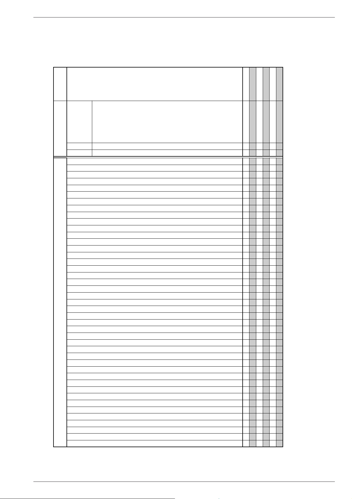
Inhaltsverzeichnis
Seite
Allgemeiner Teil ................................. 1-3…1-18
Geräteübersicht ........................................................................... 1-3
Meßgeräte / Meßmittel................................................................. 1-4
Technische Daten ........................................................................ 1-4
Bedienhinweise............................................................................ 1-5
Servicehinweise ......................................................................... 1-17
Fehlerdiagnoseprogramm............................ 2-1
Abgleichvorschriften .................................... 3-1
Platinenabbildungen
und Schaltpläne ................................. 4-1…4-34
Verdrahtungsplan......................................................................... 4-1
Blockschaltpläne .......................................................................... 4-3
• Netzteil ...................................................................................... 4-3
• Digital ........................................................................................ 4-4
• Video/Chroma ........................................................................... 4-7
• Audio......................................................................................... 4-9
• IN/OUT...................................................................................... 4-9
CP-1: Chassisplatte ................................................................... 4-11
• Oszillogramme ........................................................................ 4-14
• PW-A: Netzteil ............................................................... 4-17
• SY-A: Empfangseinheit................................................. 4-18
•
SY-A/MC-A
• TM-A: Display................................................................ 4-22
• VA-A: Video/Chroma/Audio
• AD-A: Interface
• TC-A: VPS/PDC............................................................ 4-29
TM-1: Bedienplatte..................................................................... 4-22
TB-1: Buchsenplatte .................................................................. 4-31
• TB-1: Buchsenplatte
: Laufwerksteuerung ............................................. 4-19
Bedieneinheit...................................................... 4-23
Video/Chroma/Audio
Interface
Buchsenplatte
(GV 29…) ..............................................
(GV 9000…/GV 9300…) .......................
(GV 29…) ..........................
(GV 9000…/GV 9300…) ...
(GV 29…) .....................................
(GV 9000…/GV 9300…) ..............
4-25
4-27
4-29
4-30
4-32
4-33
The regulations and safety instructions shall be valid
as provided by the "Safety" Service Manual, part
number 72010 800 0000, as well as the respective
national deviations.
GB
Table of Contents
Page
General Section.................................. 1-3…1-18
Video Recorder Overview ............................................................ 1-3
Test Equipment / Jigs .................................................................. 1-4
Specifications............................................................................... 1-4
Operating Hints .......................................................................... 1-11
Service Instructions.................................................................... 1-17
Diagnostic Programme.................................2-2
Adjustment Procedures................................3-2
Layout of the PCBs
and Circuit Diagrams ......................... 4-1…4-34
Wiring Diagram ............................................................................ 4-1
Block Circuit Diagram .................................................................. 4-3
• Power Supply............................................................................ 4-3
• Digital ........................................................................................ 4-4
• Video/Chroma .............................................................................4-7
• Audio......................................................................................... 4-9
• IN/OUT...................................................................................... 4-9
CP-1: Chassis Board ................................................................. 4-11
• Oscillograms ........................................................................... 4-14
• PW-A: Power Supply ..................................................... 4-17
• SY-A: Frontend ............................................................. 4-18
• SY-A/MC-A: Drive Control ...................................................... 4-19
• TM-A: Display................................................................ 4-22
• VA-A: Video/Chroma/Audio
• AD-A: Interface
• TC-A: VPS/PDC............................................................ 4-29
TM-1: Keyboard Control............................................................. 4-22
TB-1: Socket Board.................................................................... 4-31
• TB-1: Socket Board
Keyboard Control ............................................... 4-23
Video/Chroma/Audio
Interface
Socket Board
(GV 29…) ..............................................
(GV 9000…/GV 9300…) .......................
(GV 29…) ..........................
(GV 9000…/GV 9300…) ...
(GV 29…) ......................................
(GV 9000…/GV 9300…) ...............
4-25
4-27
4-29
4-30
4-32
4-33
Laufwerk ............................................. 5-1…5-15
Meßgeräte / Meßmittel................................................................. 5-1
Reinigung..................................................................................... 5-1
Wartung und Überprüfung des Laufwerks ................................... 5-2
Bezeichnung der wichtigsten Laufwerksteile ............................... 5-2
Überprüfung der Laufwerksfunktionen......................................... 5-4
Servicetestmode der Laufwerksfunktionen .................................. 5-4
Übersicht der Laufwerksfunktionen.............................................. 5-5
Auswechseln von Laufwerksteilen ............................................... 5-6
Einstellungen ............................................................................. 5-14
Explosionszeichnungen
und Ersatzteillisten ............................ 6-1…6-10
1 - 2 GRUNDIG Service
Drive Mechanism.............................. 5-16…5-30
Test Equipment / Jigs ................................................................ 5-16
Cleaning..................................................................................... 5-16
Maintenance and Inspection of the Drive Mechanism ............... 5-17
Names of the Main Mechanical Parts ........................................ 5-17
Checking the Mechanism Mode Positions ................................. 5-19
Operating the Mechanism in the Service Test Mode ................. 5-19
Overview of Operating Modes ................................................... 5-20
Replacing Parts of the Drive Mechanism................................... 5-21
Adjustments ............................................................................... 5-29
Exploded Views and
Spare Parts Lists................................ 6-1…6-10
GV 29…, GV 9000…, GV 9300… Allgemeiner Teil / General Section
Allgemeiner Teil / General Section
Geräteübersicht / Video Recorder Overview
GV 29 VPS
GV 29 VPS/5
GV 9000 SV
GV 9000 SV/5
GV 9300 SV
GV 9300 SV/5
S./P 4-11
S./P 4-17
S./P 4-18
S./P 4-19
S./P 4-23
S./P 4-25
S./P 4-29
S./P 4-29
CP-1: Chassisplatte / Chassis Board
· PW-A: Netzteil / Power Supply
· SY-A: Empfangseinheit / Frontend
· SY-A/MC-A: Laufwerkssteuerung / Drive Control
· TM-A: Bedieneinheit / Keyboard Control
· VA-A: Video/Chroma/Audio
· AD-A: Interface
· TC-A: VPS/PDC
• •••••
S./P 4-22 TM-1: Bedienplatte / Keyboard Control
• •••••
S./P 4-31 TB-1: Buchsenplatte / Socket Board
• •••••
CCIR, B/G/H - PAL
• •••••
CCIR, D/K - PAL
• • •
CCIR, B/G - SECAM
• •••••
CCIR, D/K - SECAM
• • •
CCIR, L/L´ - SECAM
NICAM
Modulator
• •••••
NTSC-Wiedergabe / NTSC Playback
• •••••
S-VHS-Aufnahme / S-VHS Record
S-VHS-Wiedergabe / S-VHS Playback
2 Kopf / Head (Video)
• •••
4 Kopf / Head (Video)
• •
2 Kopf / Head (Audio)
Rotierender Löschkopf / Flying Erase Head
HiFi-Stereo
Normalplay
• •••••
Longplay
• •••
Energiesparend / Low Power (Standby <2W)
• •••••
Megalogic
Data-Link
Follow TV
VPS
• •••••
PDC
• •••••
6 Timer
• •••••
SHOW VIEW
• •••
88 Programme
• •••••
Teletext "DOS"
OSD
• •••••
Kindersicherung / Child Lock
• •••••
Nachvertonung / Dubbing
Insert-Schnitt / Insert Edit
Video Index Such System (VISS)
• •••••
EURO-AV-Buchse / Socket EURO-AV
• •••••
"PAY-TV"-Buchse / Socket (EURO-AV2)
• •••
LINE-Eingangs-Buchsen / Input Sockets
LINE-Ausgangs-Buchsen / Output Sockets
Camcorder-Eingangs-Buchsen / Input Sockets
S-VHS-Buchsen / S-VHS Sockets (IN/OUT)
"SYNCHRO-EDIT"-Buchse / Socket (ø 2,5mm Klinkenbuchse / mini-minijack )
Mikrofonbuchse / Micro Jack
Kopfhörerbuchse / Headphone Jack
RS232-Buchse / Socket RS232
SAT-Steuerbuchse / SAT Remote Control
Feature-Übersicht
Table of Features
Bausteinübersicht
Table of Moduls
GRUNDIG Service 1 - 3

Allgemeiner Teil / General Section GV 29…, GV 9000…, GV 9300…
Meßgeräte / Meßmittel
Regeltrenntrafo, Zweikanaloszilloskop, Digitalmultimeter, Millivoltmeter, Frequenzzähler, Farbgenerator, Tongenerator, Stabilisiertes Netzgerät
Beachten Sie bitte das Grundig Meßtechnik-Programm, das Sie unter
folgender Adresse erhalten:
Grundig AG, Geschäftsbereich Instruments
Test- und Meßsysteme
Würzburger Str. 150, D-90766 Fürth
Tel.: 0911 / 703-4118, Fax: 0911 / 703-4130
eMail: instruments@grundig.de
Internet: http:\\www.grundig-instruments.de
Materialnummer
Testcassette (HiFi) ................................................. 92754 010 1600
• Farbtestbild mit Dropout-Einblendung
• Längsspur-Ton: 6,3kHz und 333Hz
• FM-Ton: 1kHz Vollpegel (± 50kHz Hub)
Drehmomentcassette .............................................. 75988 047 1200
Drehmomentmesser 600gf-cm ............................... 75981 311 3200
Drehmomentschraubendreher .................................... handelsüblich
Schraubendreher (eingesägt) ..................................... handelsüblich
Nylonhandschuhe ...................................................... handelsüblich
Schieblehre ................................................................. handelsüblich
Öl ............................................................................ 75988 061 7700
Fett.............................................. 75988 061 7800, 75988 061 7900
Test Equipment / Jigs
Variable isolating transformer, Dual channel oscilloscope, Digital
multimeter, Millivoltmeter, Frequency counter, Colour generator, AF
generator, Stabilized power supply
Please note the Grundig Catalog "Test and Measuring Equipment"
obtainable from:
Grundig AG, Geschäftsbereich Instruments
Test- und Meßsysteme
Würzburger Str. 150, D-90766 Fürth
Tel.: 0911 / 703-4118, Fax: 0911 / 703-4130
eMail: instruments@grundig.de
Internet: http:\\www.grundig-instruments.de
Part Number
Test cassette (HiFi) ................................................. 92754 010 1600
• Colour test pattern with dropout recording
• Longitudinal track sound: 6.3kHz and 333Hz
• FM sound: 1kHz full level (± 50kHz deviation)
Torque cassette meter ............................................ 75988 047 1200
Torque meter 600gf-cm .......................................... 75981 311 3200
Torque screwdriver ............................................ commonly available
Screwdriver (slotted) .......................................... commonly available
Nylon gloves ...................................................... commonly available
Slide gauge ........................................................ commonly available
Oil............................................................................ 75988 061 7700
Grease ........................................ 75988 061 7800, 75988 061 7900
Technische Daten
VHS-System
1/2” Video - Cassettenrecorder
Bandgeschwindigkeit .............................. 2,339cm/s (Standard play)
Aufzeichnungsgeschwindigkeit ................... 4,84m/s (Standard play)
Umspulzeit bei Vor-/Rücklauf mit E180-Cassette: ........ typisch 100s
FS-Norm
CCIR, B/G/H - PAL
CCIR, B/G - SECAM
CCIR, D/K - PAL
CCIR, D/K - SECAM
Video
Signal / Rauschabstand ........................................ ≥ 44dB (bewertet)
Auflösung ........................................................................... ca. 3MHz
Ton
Frequenzgang:
Standard play .............................................. 80Hz…10kHz (+5/-9dB)
Longplay ................................................. 80Hz…5kHz (+3,5/-6,5dB)
Signal / Rauschabstand ........................................ ≥ 39dB (bewertet)
Gleichlaufschwankung: ......................................≤ 0,3% (DIN 45507)
Netzspannung ......................................................... 220V~…240V~
Netzfrequenz ........................................................................... 50Hz
Leistungsaufnahme
– Aufnahme.......................................................................... ca. 15W
– Stand by (Modulator aus)....................................................... ≤ 6W
– Energiesparbetrieb................................................................. ≤ 2W
Umgebungstemperatur ...........................................+10°C…+40°C
Relative Luftfeuchte............................................................... ≤80%
Betriebslage ..................................................................... horizontal
Specifications
VHS-System
1/2” video cassette recorder
Tape speed ............................................. 2.339cm/s (Standard play)
Head to tape speed..................................... 4.84m/s (Standard play)
Winding time of forward wind/rewind of a E180 Cassette: typically 100s
TV standard
CCIR, B/G/H - PAL
CCIR, B/G - SECAM
CCIR, D/K - PAL
CCIR, D/K - SECAM
Video
Signal / noise ratio ............................................... ≥ 44dB (weighted)
Video resolution ................................................................. ca. 3MHz
Sound
Frequency response:
Standard play .............................................. 80Hz…10kHz (+5/-9dB)
Longplay ................................................. 80Hz…5kHz (+3.5/-6.5dB)
Signal / noise ratio ............................................... ≥ 39dB (weighted)
Wow and flutter ..................................................≤ 0.3% (DIN 45507)
Mains voltage .......................................................... 220V~…240V~
Mains frequency...................................................................... 50Hz
Power consumption
– Record .............................................................................. ca. 15W
– Stand by mode (Modulator off) .............................................. ≤ 6W
– Low power.............................................................................. ≤ 2W
Ambient temperature ...............................................+10°C…+40°C
Relative humidity ................................................................... ≤80%
Operating position ........................................................... horizontal
1 - 4 GRUNDIG Service
GV 29…, GV 9000…, GV 9300… Allgemeiner Teil / General Section
GRUNDIG Service 1 - 5
Bedienhinweise Dieses Kapitel enthält Auszüge aus der Bedienungsanleitungen. Weitergehende Informationen entnehmen Sie bitte den gerätespezifischen Bedienungsanleitungen, deren
Materialnummer Sie in den entsprechenden Ersatzteillisten finden.
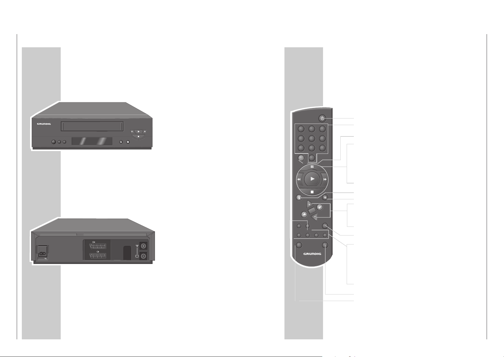
Die Vorderseite des Videorecorders
AUF EINEN BLICK
______________________________________________________
8
o
o
AA
Schaltet den Videorecorder ab.
**
Wählt Programme abwärts.
ÜÜ
Wählt Programme aufwärts.
NN
Schiebt die Cassette aus.
● Startet die Aufnahme.
rr
Bei Wiedergabe: Bildsuchlauf rückwärts;
nach Stopp: Band zurückspulen.
e
Startet die Wiedergabe.
ee
Bei Wiedergabe: Bildsuchlauf vorwärts;
nach Stopp: Band vorspulen.
■ Beendet alle Laufwerkfunktionen.
TV
DECODER/
EURO-AV2
EURO-AV1
AC IN
AC IN~ Netzbuchse für das Netzkabel zur Steckdose.
X EURO-AV1 Euro/AV-Anschluß (zum Fernsehgerät).
DECODER/
Y EURO-AV2 Euro/AV-Anschluß
(zu einem externen Gerät).
ÄÄ
Antennenbuchse (von der Hausantenne).
Ö Antennenbuchse (zum Fernsehgerät).
Die Rückseite des Videorecorders
AUF EINEN BLICK
________________________________________________________________
Die Fernbedienung
Auf dieser Seite finden Sie die wichtigsten Funktionen der Fernbedienung.
Die Bedienung entnehmen Sie bitte dem jeweiligen Kapitel dieser Bedienungsanleitung.
Richten Sie die Fernbedienung auf den Videorecorder.
88
Schaltet den Videorecorder ab (Standby).
1 … 0 Ziffern-Tasten für verschiedene Eingaben,
»0« wählt Programmplatz »
A I
«.
SV Ohne Funktion.
TIMER/V+
II Pause bei Aufnahme, Standbild bei Wiedergabe.
rr Bildsuchlauf rückwärts bei Wiedergabe;
Band rückspulen in „Stopp“.
e
Startet die Wiedergabe.
ee Bildsuchlauf vorwärts bei Wiedergabe;
Band vorspulen in „Stopp“.
■ Beendet alle Laufwerkfunktionen und schaltet den Videorecorder
in „Stopp“.
i INFO Schaltet auf das Menü und zurück auf das Fernsehbild.
● RECORD Startet die Aufnahme.
CC
DD
Wählen Programme, »+« aufwärts, »– « abwärts;
wählen in den Menüs verschiedene Funktionen.
OK Ruft Daten auf, bestätigt und speichert Daten.
FF EE
Zum Feinabstimmen der Programme;
wählen in den Menüs verschiedene Funktionen.
TIMER Aktiviert und deaktiviert die TIMER-Aufnahme.
ON/OFF
SP/LP Ohne Funktion.
CLEAR Löscht Daten, aktiviert Eingaben, setzt die Spielzeitanzeige auf
»
0:00:00
«.
MONITOR Ohne Funktion.
AUDIO Ohne Funktion.
INDEX Aktiviert die INDEX-Suchfunktion.
DUB Aktiviert die Einstellung für den Ausgangskanal des Video-
recorders.
VIDEO 2 Schaltet auf Videobedienebene 2.
TV Schaltet auf die Bedienung eines Fernsehgerätes.
Die Möglichkeiten sind auf Seite 30 beschrieben.
1 2 3
4 5 6
7 8 9
SV 0
TIMER/ V+
INFO RECORD
OK
TIMER
ON/OFF
CLEAR
SP/LP
AUDIOMONITOR INDEX DUB
TV VIDEO 2
Allgemeiner Teil / General Section GV 29…, GV 9000…, GV 9300…
1 - 6 GRUNDIG Service
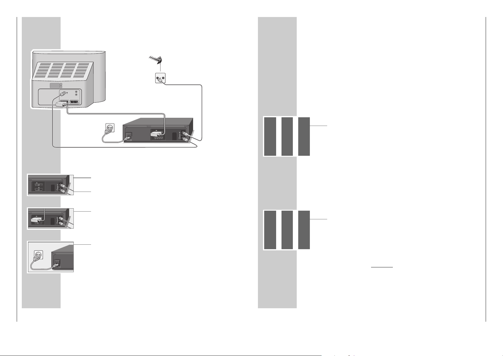
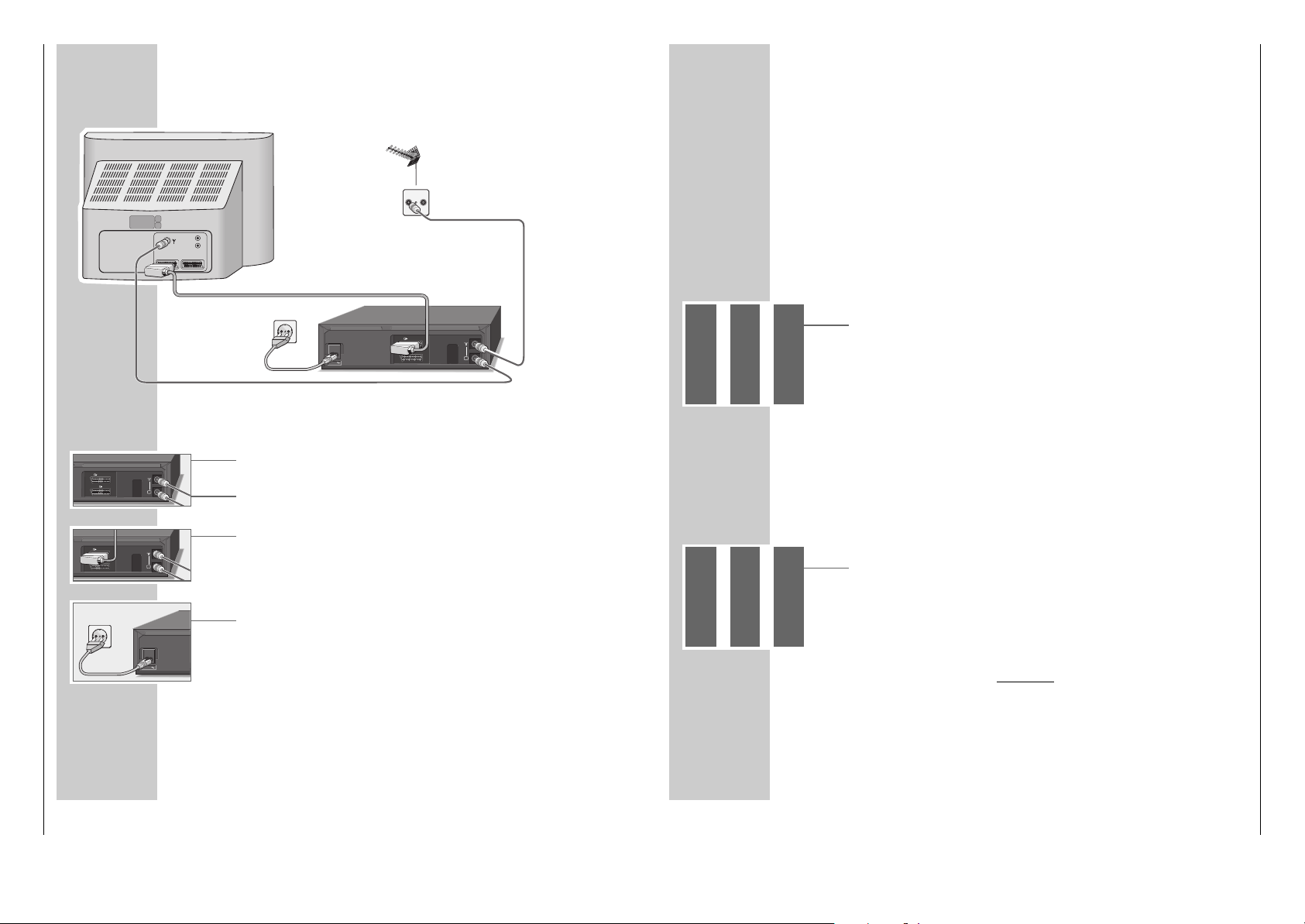
Antenne, Fernsehgerät und Netzkabel anschließen
1 Antennenkabel der Hausantenne in die Antennenbuchse »
ÄÄ
« des Videore-
corders stecken.
2 Beigepacktes Antennenkabel in die Buchse »Ö « des Videorecorders und in
die Antennenbuchse des Fernsehgerätes stecken.
3 Wenn das Fernsehgerät mit einer oder mehreren EURO-AV-Buchsen ausge-
stattet ist:
Handelsübliches EURO-AV-Kabel in die Buchse »XEURO-AV1« des
Videorecorders und in die Buchse AV 1 des Fernsehgerätes stecken.
– Der Vorteil dieses Anschlusses ist eine bessere Bild- und Tonqualität bei
Wiedergabe.
4 Beigepacktes Netzkabel in die Buchse »AC IN~« des Videorecorders
stecken.
Stecker des Netzkabels in die Steckdose stecken.
– Der Videorecorder ist jetzt in Bereitschaft (Standby).
Vorsicht:
Nur durch Ziehen des Netzsteckers ist der Videorecorder vom Stromnetz
getrennt.
ANSCHLIESSEN UND VORBEREITEN
______
1
3
4
TV
DECODER/
EURO-AV2
EURO-AV1
2
EINSTELLUNGEN
_________________________________________________________
Videorecorder und Fernsehgerät anpassen
Diese Einstellung ist nicht notwendig, wenn der Videorecorder und das Fernsehgerät mit einem EURO-AV-Kabel verbunden sind.
Vorbereiten
Fernsehgerät einschalten.
Am Fernsehgerät den Programmplatz »AV« für Recorder-Wiedergabe über das
Antennenkabel wählen.
Nehmen Sie auch die Bedienungsanleitung Ihres Fernsehgerätes zur Hand.
Anpassen
1 Videorecorder mit »
DD
« einschalten.
2 »DUB« ca. 3 Sekunden drücken.
– Anzeige am Videorecorder z.B. »
21 RF
« (21 ist der Ausgangskanal des
Videorecorders).
Der Videorecorder sendet jetzt ein „Testbild“.
3 Am Fernsehgerät im UHF-Bereich, zwischen Kanal 21 und Kanal 69, das
„Testbild“ des Videorecorders suchen (im Beispiel Kanal 21).
4 Einstellung am Fernsehgerät speichern.
5 Einstellung mit »DUB« beenden.
Bildqualität verbessern
Ist die Qualität des „Recorderbildes“ nicht zufriedenstellend oder die Qualität
eines oder mehrerer Fernseh-Programme am Fernsehgerät hat sich verschlechtert,
dann müssen Sie am Fernsehgerät einen anderen „freien“ Kanal suchen.
1 Videorecorder mit »
DD
« einschalten.
2 »DUB« ca. 3 Sekunden drücken.
– Anzeige am Videorecorder z.B. »
21 RF
« (21 ist der Ausgangskanal des
Videorecorders).
Der Videorecorder sendet jetzt ein „Testbild“.
3 Am Fernsehgerät – im UHF-Bereich, zwischen Kanal 21 und 69 – einen Kanal
suchen, der nicht mit einem Fernseh-Programm belegt ist (nur Bildflimmern am
Bildschirm und Tonrauschen).
4 Kanal mit »
** ÜÜ
« am Videorecorder einstellen, bis am Bildschirm des Fernsehgerätes das „Testbild“ erscheint.
Einstellung mit »OK« bestätigen.
5 Kanal am Fernsehgerät speichern.
6 Einstellung mit »DUB« beenden.
TV R
L
R
AV1 AV2
EURO-AV1
DECODER/
AC IN
EURO-AV2
TV
EURO-AV1
DECODER/
EURO-AV2
TV
AC IN

GV 29…, GV 9000…, GV 9300… Allgemeiner Teil / General Section
GRUNDIG Service 1 - 7
EINSTELLUNGEN
________________________________________________________________________
5
Suchlauf mit
»OK« starten.
– In der Anzeige am Videorecorder blinkt »AUTO«.
– Der Videorecorder sucht alle Fernsehkanäle nach Fernseh-Programmen ab,
sortiert und speichert sie. Der Suchlauf kann einige Minuten dauern.
– Nach Abschluß des Suchlaufs erscheint am Bildschirm die Meldung
»AUTO-SETUP DURCHGEFÜHRT!« und die Nummer des Ausgangskanal.
In der Anzeige am Videorecorder erscheint »OK«.
Hinweis:
Wenn Videorecorder und Fernsehgerät nicht mit einem EURO-AV-Kabel verbunden sind, müssen Sie die Einstellung auf Seite 11 wiederholen und am
Fernsehgerät den in der Tafel gezeigten Kanal (z.B »
CH 27
«) einstellen.
6 »OK« drücken.
– Am Bildschirm erscheint die Tafel »Uhr«.
Kontrollieren Sie Uhrzeit und Datum.
Hinweis:
Wurde die Uhrzeit nicht automatisch aktualisiert, stellen Sie diese manuell ein,
siehe Kapitel „Uhrzeit und Datum einstellen“ auf Seite 33.
7 Einstellung mit »OK« beenden.
Hinweis:
Weitere Einstellungen – wie die manuelle Suche, die Reihenfolge der FernsehProgramme nachträglich ändern, Fernseh-Programme aus der Sender-Tabelle
löschen oder einem Fernseh-Programm einen Namen geben – sind ab Seite
29 beschrieben.
EINSTELLUNGEN
________________________________________________________________________
Fernseh-Programme einstellen – automatisch
(mit ATS euro plus)
Der Videorecorder hat ein eigenes Empfangsteil. Damit kann er – unabhängig
vom Fernsehgerät – die Fernseh-Programme empfangen und aufzeichnen.
Deshalb müssen Sie die Kanäle der Fernseh-Programme am Videorecorder einstellen.
Bei dieser Einstellung wird automatisch auch die Uhrzeit aktualisiert. Voraussetzung dafür ist, auf Programmplatz 1 des Videorecorders ist ein Fernseh-Programm mit Videotext eingestellt.
Es stehen 88 Programmplätze zur Verfügung, die beliebig mit Fernseh-Programmen von der Antenne oder vom Kabelanschluß belegt werden können.
Vorbereiten
Fernsehgerät einschalten.
Am Fernsehgerät den Programmplatz »AV« für Recorder-Wiedergabe wählen.
Einstellen
1 »
DD
« drücken.
– Am Bildschirm des Fernsehgerätes erscheint die Tafel
»AUTO INSTALLATION«.
Hilfe:
Wenn am Bildschirm die Tafel »AUTO INSTALLATION« nicht erscheint:
»q« und »w« am Videorecorder gleichzeitig drücken, bis die Tafel erscheint.
2 Einstellung mit »OK« beginnen.
– Am Bildschirm erscheint die Tafel »LANGUAGE« (SPRACHE).
3 Sprache mit »
CC DD
FF EE
« wählen und mit »OK« bestätigen.
– Am Bildschirm erscheint die Tafel
»LAND«
.
4 Land (Aufstellungsort) mit »
CC DD
FF EE
« wählen.
Ist in der Tafel das benötigte Land nicht vorhanden, die Zeile
»OTHERS« (SONSTIGE) wählen.
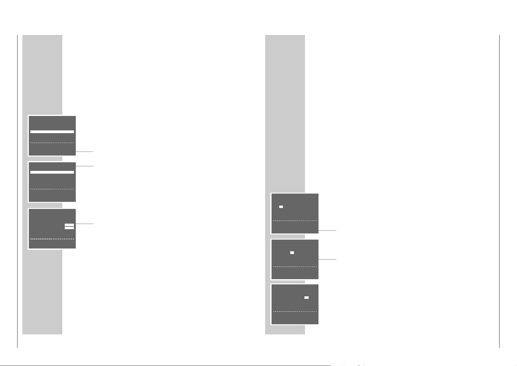
AUTO INSTALLATION
PRESS OK KEY TO START.
AUTOMATISCHE EINSTELLUNG
ZUM START DIE OK TASTE
DRÜCKEN.
OK :ENTER INFO:EXIT
LANGUAGE
ENGLISH DENMARK
DEUTSCH SVENSKA
FRANÇAIS FINLAND
ITALIANO ESPANOL
NEDERLANDS PORTUGUESE
‹›
&& %%
:SELECT
OK :ENTER INFO:EXIT
LAND
AI
BN
DK P
FIN E
D S
NL CH
F OTHERS
‹›
&& %%
:WÄHLEN
OK :EINGABE INFO:ENDE
AUTOMATISCHES SORTIEREN.
BITTE WARTEN
. – – – – – – – – – – – – – – – – – –
INFO:ENDE
AUTO-SETUP
DURCHGEFÜHRT!
VCR-AUSGANGSKANAL
WECHSELT AUF CH 27.
OK :EINGABE INFO:ENDE
UHR
ZEIT DATUM JAHR
9:03 05/0299
*
STELLEN *:AUTO - :OFF
‹›
:WÄHLEN
&& %%
:ÄNDERN
OK :EINGABE INFO:ENDE

Allgemeiner Teil / General Section GV 29…, GV 9000…, GV 9300…
1 - 8 GRUNDIG Service
SONDEREINSTELLUNGEN
_________________________________
Fernseh-Programme sortieren
Vorbereiten
Fernsehgerät einschalten.
Am Fernsehgerät den Programmplatz »AV« für Recorder-Wiedergabe wählen.
Einstellung
1 Hauptmenü mit »i INFO« aufrufen.
– Am Bildschirm erscheint die Tafel »MENÜ«.
2 Zeile »GRUNDEINSTELLUNG« mit »
CC
« oder »DD« wählen und mit »OK«
aktivieren.
– Am Bildschirm erscheint die Tafel »GRUNDEINSTELLUNG«.
3 Zeile » SENDER SORTIEREN« mit »
CC
« oder »DD« wählen und mit » OK «
aktivieren.
– Am Bildschirm erscheint die Tafel »SENDER SORTIEREN«.
4 Zeile »BEWEGEN« mit »OK« aktivieren.
– Am Bildschirm erscheint die Sendertabelle.
5 Gewünschtes Fernseh-Programm, das getauscht werden soll, mit »
CC DD
FF EE
« wählen und mit »OK« markieren.
6 Programmplatz mit dem das markierte Fernseh-Programm getauscht werden
soll mit »
CC DD
FF EE
« wählen und mit »OK« bestätigen.
Weitere Fernseh-Programme umsortieren, dazu die Pkt. 5 und 6 wiederholen.
7 Einstellung mit »i INFO« beenden.
Fernseh-Programme aus der Sendertabelle löschen
Vorbereiten
Fernsehgerät einschalten.
Am Fernsehgerät den Programmplatz »AV« für Recorder-Wiedergabe wählen.
Einstellung
1 Hauptmenü mit »i INFO« aufrufen.
– Am Bildschirm erscheint die Tafel »MENÜ«.
2 Zeile »GRUNDEINSTELLUNG« mit »
CC
« oder »DD« wählen und mit »OK«
aktivieren.
– Am Bildschirm erscheint die Tafel »GRUNDEINSTELLUNG«.
3 Zeile » SENDER SORTIEREN« mit »
CC
« oder »DD« wählen und mit » OK «
aktivieren.
– Am Bildschirm erscheint die Tafel »SENDER SORTIEREN«.
SENDER SORTIEREN
BEWEGEN
LÖSCHEN
NAME
&& %%
:WÄHLEN
OK :EINGABE INFO:ENDE
BEWEGEN
1ARD 17----- 13----2ZDF 18----- 14----3RTL1 19----- 15----4RTL2 10----- 16----5SAT1 11----- 17-----
SONDEREINSTELLUNGEN
________________________________________________________
4 Zeile »LÖSCHEN« mit »
CC
« oder »DD« wählen und mit »OK« aktivieren.
– Am Bildschirm erscheint die Sendertabelle.
5 Gewünschtes Fernseh-Programm, das gelöscht werden soll, mit »
CC DD
FF EE
« wählen und mit »CLEAR« löschen.
6 Weitere Fernseh-Programme löschen, dazu Pkt.
5
wiederholen.
7 Einstellung mit »i INFO« beenden.
Namen der Fernseh-Programme ändern oder
eingeben
Vorbereiten
Fernsehgerät einschalten.
Am Fernsehgerät den Programmplatz »AV« für Recorder-Wiedergabe wählen.
Einstellung
1 Hauptmenü mit »i INFO« aufrufen.
– Am Bildschirm erscheint die Tafel »MENÜ«.
2 Zeile »GRUNDEINSTELLUNG« mit »
CC
« oder »DD« wählen und mit »OK«
aktivieren.
– Am Bildschirm erscheint die Tafel »GRUNDEINSTELLUNG«.
3 Zeile » SENDER SORTIEREN« mit »
CC
« oder »DD« wählen und mit » OK «
aktivieren.
– Am Bildschirm erscheint die Tafel »SENDER SORTIEREN«.
4 Zeile » NAME« mit »
CC
« oder »DD« wählen und mit » OK « aktivieren.
– Am Bildschirm erscheint die Sendertabelle.
5 Gewünschtes Fernseh-Programm, für das ein Namen eingegeben werden soll,
mit »
CCDD
FF EE
« wählen und mit »OK« bestätigen.
– Die erste Stelle des Namens ist markiert.
6 Zeichen mit »
CC
« oder »DD« eingeben, nächste Stelle mit »
FF
« oder »EE«
wählen und Eingaben für die restlichen Stellen (max. 5 Stellen) wiederholen.
Einstellung mit »OK« speichern.
7 Weitere Namen vergeben, dazu die Pkt.
5
und 6wiederholen.
8 Einstellung mit »i INFO« beenden.
SENDER SORTIEREN
BEWEGEN
LÖSCHEN
NAME
&& %%
:WÄHLEN
OK :EINGABE INFO:ENDE
SENDER SORTIEREN
BEWEGEN
LÖSCHEN
NAME
&& %%
:WÄHLEN
OK :EINGABE INFO:ENDE
NAME
1ARD 17----- 13----2ZDF 18----- 14----3RTL1 19----- 15----4RTL2 10----- 16----5SAT1 11----- 17-----
GV 29…, GV 9000…, GV 9300… Allgemeiner Teil / General Section
GRUNDIG Service 1 - 9
Fernseh-Programme einstellen,
durch manuelle Eingabe
Wenn Ihnen die Kanalzahlen/Sonderkanalzahlen der jeweiligen Fernseh-Programme nicht bekannt sind, oder wenn der Recorder ein Fernseh-Programm mit
dem Suchlauf-Speicher-System nicht finden konnte, dann können Sie diese Fernseh-Programme manuell eingeben.
Vorbereiten
Fernsehgerät einschalten.
Am Fernsehgerät den Programmplatz »AV« für Recorder-Wiedergabe wählen.
Einstellung
1 Hauptmenü mit »i INFO« aufrufen.
2 Zeile »GRUNDEINSTELLUNG« mit »
CC
« oder »DD« wählen und mit »OK«
aktivieren.
3 Zeile »SENDEREINSTELLUNG« mit »OK« aktivieren.
– Am Bildschirm erscheint die Tafel zur Sendereinstellung.
Die Zeile »PROGRAMM« ist markiert.
4 Mit »
FF
« oder »EE« den gewünschten Programmplatz wählen, auf dem das
neue Fernseh-Programm gespeichert werden soll.
Hinweis:
Im Hintergrund der Tafel erscheint das aktuelle Fernseh-Programm. Wenn der
Text der Tafel dadurch gestört ist, »DUB« drücken, die Tafel wird blau hinterlegt.
5 Zeile »KANAL« mit »
CC
« oder »DD« wählen.
6 Fernseh-Programm mit »
FF
« oder »EE« einstellen.
7 Fernseh-Programm (wenn nötig) feinabstimmen, dazu mit »
CC
« oder »DD«
die Zeile »FEINABSTIMMUNG« anwählen und mit »FF« oder »EE« verändern.
8 Zeile »AUSLASSEN« mit »
CC
« oder »DD« wählen und mit »EE« »AUS«
wählen.
9 Einstellung für diesen Programmplatz mit »OK« speichern.
Weitere Fernseh-Programme einstellen, dazu die Zeile »PROGRAMM« mit
»CC« oder »DD« wählen und die Pkt. 4 bis 9 wiederholen.
10
Einstellung mit »i INFO« beenden.
SONDEREINSTELLUNGEN
________________________________________________________
GRUNDEINSTELLUNG
SENDEREINSTELLUNG
SENDER SORTIEREN
UHR
SPRACHE
&& %%
:WÄHLEN
OK :EINGABE INFO:ENDE
PROGRAMM ARD 01
➔
KANAL C06
FEINEINSTELLUNG
‹
›
DECODER EIN AUS
AUSLASSEN EIN AUS
&& %%
:WÄHLEN‹›:ÄNDERN
MENÜ
TIMER
MODE
GRUNDEINSTELLUNG
&& %%
:WÄHLEN
OK :EINGABE INFO:ENDE
UHRZEIT UND DA TUM EINSTELLEN
________
Die Digitaluhr des Videorecorders läuft ca. 1 Stunde weiter, auch wenn der
Videorecorder vom Stromnetz getrennt ist.
Die Uhrzeit ist in der Anzeige jedoch nicht sichtbar.
Uhrzeit und Datum automatisch aktualisieren
Wenn auf Programmplatz 1 des Videorecorders ein Fernseh-Programm mit
Videotext eingestellt ist, dann aktualisiert der Videorecorder damit seine „interne“
Uhr.
Diese Aktualisierung wird regelmäßig an Sonntagen zwischen 3 Uhr und 6 Uhr
durchgeführt, dadurch erkennt der Videorecorder auch die Sommer-/Winterzeitumstellung.
Zum Aktualisieren von Uhrzeit und Datum Videorecorder mit »88« abschalten
(Standby-Betrieb).
Uhrzeit und Datum manuell einstellen
Vorbereiten
Fernsehgerät einschalten.
Am Fernsehgerät den Programmplatz »AV« für Recorder-Wiedergabe wählen.
Videorecorder mit »DD« einschalten.
Einstellung
1 Hauptmenü mit »i INFO« aufrufen.
2 Zeile »GRUNDEINSTELLUNG« mit »
CC
« oder »DD« wählen und mit »OK«
aktivieren.
3 Zeile »UHR« mit »
CC
« oder »DD« wählen und mit »OK« aktivieren.
– Am Bildschirm erscheint die Tafel »UHR«, die Anzeige »ZEIT« ist markiert.
4 Mit »
CC
« oder »DD« die Stunden eingeben, danach »EE« drücken und mit
»CC« oder »DD« die Minuten eingeben.
5 Zeile »DATUM« mit »
EE
« wählen und mit »CC« oder »DD« den Tag einge-
ben, danach »EE« drücken und mit »CC« oder »DD« den Monat eingeben.
6 Zeile »JAHR« mit »
EE
« wählen und mit »CC« oder »DD« eingeben.
Hinweis:
– Die Anzeige »*« bedeutet Automatische Aktualisierung der Uhrzeit an.
Zum Abschalten dieser Funktion die Anzeige »*« mit »EE« wählen und mit
»CC« oder »DD« abschalten.
7 Einstellung mit »OK« beenden.
UHR
ZEIT DATUM JAHR
12:–– – –/– – ––
*
ZEIT:24HR ANZEIGE
‹›
:WÄHLEN
&& %%
:ÄNDERN
INFO:ENDE
UHR
ZEIT DATUM JAHR
12:00 10/5 99
*
‹›
:WÄHLEN
&& %%
:ÄNDERN
OK :EINGABE INFO:ENDE
UHR
ZEIT DATUM JAHR
12:00 10 /–– ––
*
DATUM: TAG
‹›
:WÄHLEN
&& %%
:ÄNDERN
INFO:ENDE

Allgemeiner Teil / General Section GV 29…, GV 9000…, GV 9300…
1 - 10 GRUNDIG Service
BESONDERHEITEN
____________________________________________________
Die Funktionen „Bildschirmanzeigen aus- oder einblenden“, „Ausschalt-Automatik aktivieren“, „NTSC-Wiedergabe“, „DECODER-EURO-AV2-Buchsen für externe Geräte anpassen“, „Kindersicherung“ und „Bedienebene des Videorecorders
wählen“ können Sie aus dem Menü »MODE« wählen.
Menü »MODE« wählen
1 Fernsehgerät einschalten.
2 Am Fernsehgerät den Programmplatz »AV« für Recorder-Wiedergabe
wählen.
3 Videorecorder mit »
DD
« einschalten.
4 Hauptmenü mit »i INFO« aufrufen.
– Am Bildschirm erscheint die Tafel »MENÜ«.
5 Zeile »MODE« mit »
CC
« oder »DD« wählen und mit »OK« aktivieren.
– Am Bildschirm erscheint die Tafel »MODE«.
6 Wählen Sie aus der Tafel »MODE« die gewünschte Funktion, die weitere
Bedienung entnehmen Sie bitte den folgenden Kapiteln, jeweils ab Pkt. 1.
Bildschirmanzeigen aus- oder einblenden
(OSD – On Screen Display)
1 Zeile »OSD MODE« mit »
CC
« oder »DD« wählen.
2 »AUS« mit »
EE
« oder »AUTO« mit »FF« wählen und mit »OK«
bestätigen.
Ausschaltautomatik aktivieren
Ist die Abschaltautomatik aktiviert, schaltet der Videorecorder nach 2- oder 6
Stunden automatisch ab.
1 Zeile »ABSCHALTEN« mit »
CC
« oder »DD« wählen.
2
» AUS«, »2 HR« oder » 6 HR« mit »FF« oder »EE« wählen und mit » OK«
bestätigen.
NTSC-Wiedergabe
Mit dieser Einstellung wählen Sie die Farbnorm der Cassettenwiedergabe für das
angeschlossene Fernsehgerät an Buchse »X EURO-AV1«. Wählen Sie die
Einstellung PAL-TV für ein PAL-Fernsehgerät oder die Einstellung NTSC 443 für
ein Multinorm-Fernsehgerät.
1 Zeile »NTSC PB« mit »
CC
« oder »DD« wählen.
2
» PAL-TV« mit »FF« oder » NTSC 443 (= Multinorm)« mit »EE« wählen und mit
»OK« bestätigen.
MODE
➔
OSD-MODE AUTO AUS
ABSCHALTEN AUS 2HR 6HR
NTSC PB PAL-TV NTSC443
AV-2 AV-IN DECODER
SPERRE EIN11 AUS
VCR NO. 1 2
&& %%
:WÄHLEN‹›:ÄNDERN
OK :EINGABE INFO:ENDE
MODE
➔
OSD-MODE AUTO AUS
ABSCHALTEN AUS 2HR 6HR
NTSC PB PAL-TV NTSC443
AV-2 AV-IN DECODER
SPERRE EIN11 AUS
VCR NO. 1 2
&& %%
:WÄHLEN‹›:ÄNDERN
OK :EINGABE INFO:ENDE
MODE
OSD-MODE AUTO AUS
➔
ABSCHALTEN AUS 2HR 6HR
NTSC PB PAL-TV NTSC443
AV-2 AV-IN DECODER
SPERRE EIN11 AUS
VCR NO. 1 2
&& %%
:WÄHLEN‹›:ÄNDERN
OK :EINGABE INFO:ENDE
MODE
OSD-MODE AUTO AUS
ABSCHALTEN AUS 2HR 6HR
➔
NTSC PB PAL-TV NTSC443
AV-2 AV-IN DECODER
SPERRE EIN11 AUS
VCR NO. 1 2
&& %%
:WÄHLEN‹›:ÄNDERN
OK :EINGABE INFO:ENDE
BESONDERHEITEN
_____________________________________________________________________
DECODER/EURO-AV2-Buchse für externe Geräte
anpassen
Mit dieser Einstellung passen Sie die DECODER/EURO-AV2-Buchse an das extere Gerät an. Einstellung AV-IN benötigen Sie für einen zweiten Videorecorder
oder einen Satellitenreceiver, Einstellung DECODER benötigen Sie für einen PAYTV-Decoder.
1 Zeile »AV-2« mit »
CC
« oder »DD« wählen.
2
»AV-IN« mit »FF« oder »DECODER« mit »EE« wählen und mit »OK« bestätigen.
Kindersicherung
Mit der Kindersicherung können Sie alle Funktionen des Videorecorders
verriegeln.
1 Zeile »SPERRE« mit »
CC
« oder »DD« wählen.
2
»EIN« mit »FF« wählen und mit »OK« bestätigen.
– Der Bildschirm des Fernsehgerätes wird blau.
3 Kindersicherung aufheben, dazu Einstellung wiederholen und in Pkt. 2
»AUS«
mit »EE« wählen.
Bedienebene des Videorecorders wählen
Mit dieser Fernbedienung können verschiedene GRUNDIG Videorecorder unabhängig voneinander bedient werden.
Fragen Sie Ihren Fachhändler, welche GRUNDIG Videorecorder hierfür geeignet
sind.
Damit sich beide Videorecorder nicht gegenseitig stören, muß die Bedienebene
des GV 9300 umgestellt werden.
1 Zeile »VCR NO.« mit »
CC
« oder »DD« wählen.
2 »2« mit »
EE
« (oder »1« mit »FF«) wählen und mit »OK« bestätigen.
– Der GV 9300 ist auf Bedienebene 2 eingestellt. Für die Bedienung des
GV 9300 muß jetzt »VIDEO 2« gedrückt und gehalten werden und dabei
die jeweils benötigte Taste gedrückt werden.
Dauerlauf-Wiedergabe
Ist diese Funktion eingeschaltet, spult der Videorecorder am Ende des Videobandes die Cassette automatisch zurück und beginnt erneut mit der Wiedergabe.
1 Wiedergabe mit »e« starten.
2 »e« am Videorecorder drücken und halten und gleichzeitig » rr« am
Videorecorder drücken.
3 Dauerlauf-Wiedergabe mit »■ « beenden.
MODE
OSD-MODE AUTO AUS
ABSCHALTEN AUS 2HR 6HR
NTSC PB PAL-TV NTSC443
AV-2 AV-IN DECODER
➔
SPERRE EIN11 AUS
VCR NO. 1 2
&& %%
:WÄHLEN‹›:ÄNDERN
OK :EINGABE INFO:ENDE
MODE
OSD-MODE AUTO AUS
ABSCHALTEN AUS 2HR 6HR
NTSC PB PAL-TV NTSC443
AV-2 AV-IN DECODER
SPERRE EIN11 AUS
➔
VCR NO. 1 2
&& %%
:WÄHLEN‹›:ÄNDERN
OK :EINGABE INFO:ENDE
MODE
OSD-MODE AUTO AUS
ABSCHALTEN AUS 2HR 6HR
NTSC PB PAL-TV NTSC443
➔
AV-2 AV-IN DECODER
SPERRE EIN11 AUS
VCR NO. 1 2
&& %%
:WÄHLEN‹›:ÄNDERN
OK :EINGABE INFO:ENDE

GV 29…, GV 9000…, GV 9300… Allgemeiner Teil / General Section
GRUNDIG Service 1 - 11
Operating Hints This chapter contains excerpts from the operating instructions. For further particulars please refer to the appropriate user manuals the part numbers of which are indicated in the
relevant spare parts lists.
Front side of the video recorder
A T A GLANCE
_________________________________________________________________
Rear side of the video recorder
AA
Switches the video recorder off.
**
Selects programmes downwards.
ÜÜ
Selects programmes upwards.
NN
Ejects the cassette.
● Starts recording.
rr
During playback: reverse picture search;
after stop: fast rewind.
e
Starts playback.
ee
During playback: forward picture search;
after stop: fast forward wind.
■ Ends all drive mechanism functions.
AC IN~ Socket for mains cable to mains supply socket.
X EURO-AV1 Euro/AV connector (for TV set).
DECODER
Y EURO-AV2 Euro/AV connector (for external device).
ÄÄ
Aerial socket (for domestic aerial).
Ö Aerial socket (for TV set).
AT A GLANCE
______________________________________________________________________
The remote control
On this page you will find a brief description of the important remote control
functions. Refer to the corresponding chapters of this manual for more information on operation.
Direct the remote control at the video recorder.
88
Switches the video recorder off (standby).
1 … 0 Numeric buttons for various entries ,
the »0« button selects the »
A I
« programme position.
SV Initiates programmed recording with ShowView.
TIMER/V+
II Pause in recording mode, freeze-frame in playback mode.
rr Reverse picture search during playback,
fast rewind after stop.
e
Starts playback.
ee Forward picture search during playback,
fast forward after stop.
■ Ends all drive mechanism functions and switches the vidoe
rocorder to “stop”.
i INFO Switches to the menu and back to the TV picture.
● RECORD Starts recording.
CC
DD
Select channels, »+« up, »– « down;
select various functions in the menus.
OK Calls up, confirms and stores data.
FF EE
Finetuning;
select various functions in the menus.
TIMER Activates and de-activates programmed recording.
ON/OFF
SP/LP Switches between longplay mode and standard play mode.
CLEAR Clears data, activates entries, resets the playing time display to
»
0:00:00
«.
MONITOR Switches the picture screen between TV picture and video recor-
der picture (monitor mode).
AUDIO No function.
INDEX Activates the INDEX search function.
DUB Activates the setting for the output channel of the video recorder.
VIDEO 2 Switches to the video control address 2.
TV Swiches to TV control mode.
See page 37 for the possible functions.
AC IN
o
o
8
DECODER/
EURO-AV1
EURO-AV2
TV
1 2 3
4 5 6
7 8 9
SV 0
TIMER/ V+
INFO RECORD
OK
TIMER
ON/OFF
CLEAR
SP/LP
AUDIOMONITOR INDEX DUB
TV VIDEO 2
Allgemeiner Teil / General Section GV 29…, GV 9000…, GV 9300…
1 - 12 GRUNDIG Service
Connecting the aerial, TV set and mains cable
1 Connect the aerial cable from the domestic aerial with the aerial socket
»ÄÄ« of the video recorder.
2 Connect the aerial cable supplied with the »Ö « socket of the video recorder
and the aerial socket of the TV set.
3 If the TV set is equipped with one or several EURO-AV sockets:
connect the »XEURO-AV1« socket of the video recorder with the AV 1
socket of the TV set using a commercially available EURO-AV cable.
– The advantage of this connection is a better picture and sound quality
during playback.
4 Connect the mains cable supplied with the »AC IN ~« socket of the video
recorder.
Connect the mains cable with the mains supply socket.
– The video recorder is now in standby.
Attention:
The video recorder is isolated from the mains only when the mains cable is
disconnected from the mains supply socket.
CONNECTING AND PREPARATION
________
1
3
4
2
SETTINGS
____________________________________________________________________________
Adjusting the TV set to the video recorder
This adjustment is not necessary if the video recorder and the TV set are
connected with a EURO-AV cable.
Preparation
Switch the TV set on.
On the TV set, select the »AV« programme position for video playback via the
aerial socket.
Consult also the user manual of your TV set.
Adjustment
1 Switch the video recorder on using the »
DD
« button.
2 Press the »DUB« button for about 3 seconds.
– »
21 RF
«, for example, is displayed on the video recorder (21 is the output
channel of the video recorder).
The video recorder now emits a test pattern.
3 Search the test pattern on the TV set in the UHF range on a channel between
21 and 69 (channel 21 in the example).
4 Store the setting on the TV set.
5 Press the »DUB« button to end the setting.
Improving the picture quality
If the quality of the “recorder picture” is poor, or the picture quality of one or
more TV programmes on the TV set gets worse, you must search a different “free”
channel on the TV set.
1 Switch the video recorder on using the »
DD
« button.
2 Press the »DUB« button for about 3 seconds.
– »
21 RF
«, for example, is displayed on the video recorder (21 is the output
channel of the video recorder).
The video recorder now emits a test pattern.
3 On the TV set in the UHF range between channel 21 and channel 69, search
for a “free“ channel on which no TV programme is received (only snow and
sound noise).
4 Use the »
** ÜÜ
« buttons on the video recorder to change the output channel
of the video recorder until the test pattern appears on the picture screen of the
TV set.
Press the »OK« button to store the setting.
5 Store the channel on the TV set.
6 Press the »DUB« button to end the setting.
TV R
L
R
AV1 AV2
EURO-AV1
DECODER/
AC IN
EURO-AV2
TV
EURO-AV1
DECODER/
EURO-AV2
TV
EURO-AV1
DECODER/
EURO-AV2
TV
AC IN

GV 29…, GV 9000…, GV 9300… Allgemeiner Teil / General Section
GRUNDIG Service 1 - 13
SETTINGS
____________________________________________________________________________________
5 Press the »OK« button.
– The »CLOCK« table appears on the picture screen.
Check the time and the date.
Note:
If the time has not been updated automatically, it must be set manually, see
chapter “Setting the Time and Date” on page 34.
6 Press the »OK« button to end the setting.
Note:
Further settings such as manual channel search, changing the order of the
channels at a later date, clearing TV channels from the station table, or
assigning station names, are described from page 30 on.
SETTINGS
____________________________________________________________________________________
Channel programming with the automatic tuning
system ATS euro plus
The recorder has a built-in receiver. It can therefore receive and record television
programmes independently of the TV set.
For this, you must programme the TV channels on the video recorder.
When carrying out this function, the time is automatically updated, provided a TV
programme with teletext is received on programme position 1.
88 programme positions are available which can be assigned as desired to TV
channels received via the aerial or the cable system.
Preparation
Switch the TV set on.
Select the »AV« programme position for video playback on the TV set.
Programming
1 Press the »
DD
« button.
– The »AUTO INSTALLATION« table appears on the picture screen of the
TV set.
Help:
If the »AUTO INSTALLATION« table does not appear, press the»q« and »w«
buttons on the video recorder at the same time until the table appears.
2 Initiate programming with the »OK« button.
– The »LANGUAGE« table appears on the picture screen.
3 Use the »
CC DD
FF EE
« buttons to select the desired language.
4
Press the
»OK« button to start the automatic tuning system.
– »AUTO« flashes in the video recorder’s display.
– The recorder searches all channel numbers for TV stations, then sorts and
stores them. This can take several minutes.
– When the search is completed, the message »AUTO-SETUP COMPLETED!«
and the number of the output channel appear on the picture screen.
»OK« appears in the video recorder’s display.
Note:
If the video recorder and the TV set are not connected with a EURO-AV cable,
you must repeat the setting on page 11 and tune the TV set to the channel
(e.g.»
CH 27
«) indicated in the table.
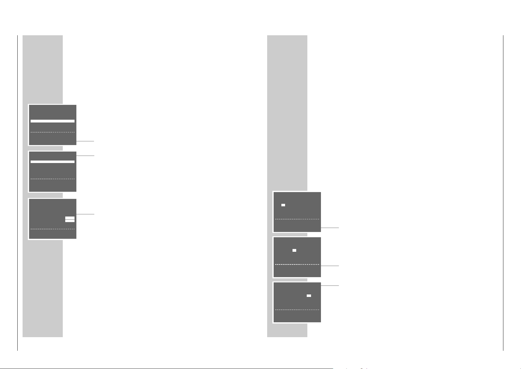
AUTO INSTALLATION
PRESS OK KEY TO START.
AUTOMATISCHE EINSTELLUNG
ZUM START DIE OK TASTE
DRÜCKEN.
OK :ENTER INFO:EXIT
LANGUAGE
ENGLISH DENMARK
DEUTSCH SVENSKA
FRANÇAIS FINLAND
ITALIANO ESPANOL
NEDERLANDS PORTUGUESE
‹›
&& %%
:SELECT
OK :ENTER INFO:EXIT
CLOCK
TIME DATE YEAR
9:03 05/0299
*
ADJUST *:AUTO - :OFF
‹›
:SELECT
&& %%
:CHANGE
OK :ENTER INFO:EXIT
AUTO-SETUP COMPLETED!
VCR OUTPUT CHANNEL
WILL CHANGE TO CH 27.
OK :ENTER INFO:EXIT
AUTOMATIC SORTING
PLEASE WAIT
. – – – – – – – – – – – – – – – – – –
INFO:EXIT

Allgemeiner Teil / General Section GV 29…, GV 9000…, GV 9300…
1 - 14 GRUNDIG Service
SPECIAL SETTINGS
_____________________________________________________________________
4 Select the »CANCEL« line using the »
CC
« or »DD« button then activate it with
the »OK« button.
– The station table appears on the picture screen.
5 Select the channel to be cleared using the »
CC DD
FF EE
« buttons then clear
it with the »CLEAR« button.
6 To clear further channels, repeat the step
5
.
7 Press the »i INFO« button to end the setting.
Changing or entering station names
Preparation
Switch the TV set on.
Select the »AV« programme position for video playback on the TV set.
Setting
1 Call up the main menu with the »i INFO« button.
– The »MENU« table appears on the picture screen.
2 Select the » INSTALLATION« line using the »
CC
« or »DD« button then activate it with the »OK« button.
– The »INSTALLATION« table appears on the picture screen.
3 Select the » CHANNEL SORT « line using the »
CC
« or »DD« button then
activate it with the »OK« button.
– The »CHANNEL SORT« table appears on the picture screen.
4 Select the »NAME« line using the »
CC
« or »DD« button then activate it with
the »OK« button.
– The station table appears on the picture screen.
5 Use the »
CC DD
FF EE
« buttons to select the channel for which you wish to
enter a name then confirm with the »OK« button.
– The first position of the name is marked.
6 Use the »
CC
« or »DD« button to enter the desired character, use the »
FF
«
or »EE« button to select the next position, then repeat these steps for the
remaining positions (max. 5 positions).
Store the setting with the »OK« button.
7 To assign further names repeat the steps
5
and 6.
8 Press the »i INFO« button to end the setting.
CHANNEL SORT
MOVE
CANCEL
NAME
&& %%
:SELECT
OK :ENTER INFO:EXIT
CHANNEL SORT
MOVE
CANCEL
NAME
&& %%
:SELECT
OK :ENTER INFO:EXIT
NAME
1ARD 17----- 13----2ZDF 18----- 14----3RTL1 19----- 15----4RTL2 10----- 16----5SAT1 11----- 17-----
SPECIAL SETTINGS
____________________________________________________
Re-sorting TV channels
Preparation
Switch the TV set on.
Select the »AV« programme position for video playback on the TV set.
Setting
1 Call up the main menu with the »i INFO« button.
– The »MENU« table appears on the picture screen.
2 Select the »INSTALLATION « line using the »
CC
« or »DD« button then activate it with the »OK« button.
– The »INSTALLATION « table appears on the picture screen.
3 Select the » CHANNEL SORT« line using the »
CC
« or »DD« button then
activate it with the »OK« button.
– The »CHANNEL SORT« table appears on the picture screen.
4 Activate the »MOVE« line with the »OK« button.
– The station table apears on the picture screen.
5 Use the »
CC DD
FF EE
« buttons to select the channel to be moved then mark it
with the »OK« button.
6 Select the programme position to be exchanged with the marked position
using the »
CC DD
FF EE
« buttons then confirm with the »OK« button.
To re-sort further programme positions, repeat the steps 5 and 6
7 Press the »i INFO« button to end the setting.
Clearing TV channels from the station table
Preparation
Switch the TV set on.
Select the »AV« programme position for video playback on the TV set.
Setting
1 Call up the main menu with the »i INFO« button.
– The »MENU« table appears on the picture screen.
2 Select the »INSTALLATION « line using the »
CC
« or »DD« button then activate it with the »OK« button.
– The »INSTALLATION « table appears on the picture screen.
3 Select the » CHANNEL SORT« line using the »
CC
« or »DD« button then
activate it with the »OK« button.
– The »CHANNEL SORT« table appears on the picture screen.
CHANNEL SORT
MOVE
CANCEL
NAME
&& %%
:SELECT
OK :ENTER INFO:EXIT
MOVE
1ARD 17----- 13----2ZDF 18----- 14----3RTL1 19----- 15----4RTL2 10----- 16----5SAT1 11----- 17-----
GV 29…, GV 9000…, GV 9300… Allgemeiner Teil / General Section
GRUNDIG Service 1 - 15
Manual channel programming
If you know the channel/special channel numbers of the TV stations you wish to
programme, or if the recorder could not find a TV station with the help of the
automatic tuning system, you can programme the channels manually.
Preparation
Switch the TV set on.
Select the »AV« programme position for video playback on the TV set.
Setting
1 Call up the main menu with the »i INFO« button.
2 Select the » INSTALLATION « line using the »
CC
« or »DD« button then acti-
vate it with the »OK« button.
3 Activate the »CHANNEL PRESET« line with the »OK« button.
– The table for channel programming appears on the picture screen.
The »PRESET« line is marked.
4 Use the »
FF
« or »EE« button to select the programme position on which the
new TV channel is to be stored.
Note:
The current TV programme appears in the background of the station table. If
this disturbs you, press the »DUB« button to get a blue background instead of
the TV picture.
5 Select the »SYSTEM« line using the »
CC
« or »DD« button then select the TV
system required: »B/G« with the »FF«,´button, »D/K« with the »EE«
button.
6 Select the »CHANNEL« line using the »
CC
« or »DD« button.
7 Select the desired channel using the »
FF
« or »EE« button.
8 If finetuning is required, select the » FINETUNING« line with the »
CC
« or
»DD« button then use the »FF« or »EE« button for finetuning.
9 Select the »SKIP« line using the »
CC
« or »DD« button then use the »EE«
button to select »OFF«.
10Store the setting for this programme position with the »OK« button.
To programme further channels, select the »PRESET« line using the »CC« or
»DD« button then repeat the steps 4 to 10.
11
Press the »i INFO« button to end the setting.
SPECIAL SETTINGS
_____________________________________________________________________
INSTALLATION
CHANNEL PRESET
CHANNEL SORT
CLOCK
LANGUAGE
&& %%
:SELECT
OK :ENTER INFO:EXIT
PRESET ARD 01
➔
SYSTEM B/G D/K
CHANNEL C06
FINE TUNING
‹
›
DECODER ON OFF
SKIP ON OFF
&& %%
:SELECT
‹›
:CHANGE
MENU
TIMER
MODE
INSTALLATION
&& %%
:SELECT
OK :ENTER INFO:EXIT
SETTING THE TIME AND DA TE
______________________
The digital clock of the recorder continues running for approximately 1 hour even
when the recorder is disconnected from the mains.
However, the time is not visible in the display
Automatic updating
If a TV channel which has Teletext is set on programme position 1 of the recorder,
the recorder updates automatically its internal clock.
This updating is regularly carried out every Sunday between 3 and 6 hours a.m.
This also means that the recorder will recognize the change from summer to
winter time.
For updating the time and date, switch the video recorder off using the »88«
button (standby mode).
Manual setting
Preparation
Switch the TV set on.
Select the »AV« programme position for video playback on the TV set.
Switch the video recorder on using the »DD« button.
Setting
1 Call up the main menu with the »i INFO« button.
2 Select the » INSTALLATION« line using the »
CC
« or »DD« button then acti-
vate it using the »OK« button.
3 Select the »CLOCK« line with the »
CC
« or »DD« button then activate it with
the »OK « button.
– The »CLOCK« table appears on the picture screen, the »TIME« item is
marked.
4 Use the »
CC
« or »DD« button to enter the hours, then press the »EE« button
and enter the minutes with the »CC« or »DD« button.
5 Select »DATE« with the »
EE
« button, enter the day with the »CC« or »DD«
button, then press the »EE« button and enter the month with the »CC« or
»DD« button.
6 Select » YEAR« with the »
EE
« button then enter the year with the »CC« or
»DD« button.
Note:
– The »*« sign signals automatic updating of the clock. To switch this function
off, select the »*« sign with the »EE« button then use the »CC« or »DD«
button to switch it off.
7 Store the setting with the »OK« button.
CLOCK
TIME DATE YEAR
12:–– – –/– – ––
*
TIME:24HR INDICATION
‹›
:SELECT
&& %%
:CHANGE
INFO:EXIT
CLOCK
TIME DATE YEAR
12:00 10/5 99
*
‹›
:SELECT
&& %%
:CHANGE
OK :ENTER INFO:EXIT
CLOCK
TIME DATE YEAR
12:00 10 /–– ––
*
DATE : DAY
‹›
:SELECT
&& %%
:CHANGE
INFO:EXIT

Allgemeiner Teil / General Section GV 29…, GV 9000…, GV 9300…
1 - 16 GRUNDIG Service
SPECIAL FUNCTIONS
________________________________________________________________
Adjusting the DECODER/EURO-AV2 socket for external
devices
With this function you can adjust the DECODER/EURO-AV2 socket to an external
device. The AV-IN setting is required for a second video recorder or a satellite
receiver, the DECODER setting is required for a PAY-TV decoder.
1 Select the »AV-2« line with the »
CC
« or »DD« button.
2 Select »AV-IN« with the »
FF
« button, or »DECODER« with the »EE« button,
then confirm with the »OK« button.
Child lock
The child lock allows you to lock all functions of the video recorder.
1 Select the »LOCK« line with the »
CC
« or »DD« button.
2 Select »ON« with the »
FF
« button then confirm with the »OK« button.
– The picture screen of the TV set turns blue.
3 To de-activate the child lock, repeat the setting but select » OFF« in step 2
using the »EE« button.
Selecting the video recorder’s control address
Your remote control can be used to operate different GRUNDIG video recorders
independently of one another.
Ask your specialized dealer which GRUNDIG video recorders are suited.
To ensure that the two video recorders do not disturb each other, the control
address of the GV 9300 must be changed.
1 Select the »VCR NO.« line with the »
CC
« or »DD« button.
2 Select »2« with the »
EE
« button (or »1« with the »FF« button) then confirm
with the »OK« button.
– When selecting 2, the GV 9300 is set to the remote control address 2. In
order to control the GV 9300 you now must press and hold down the
»VIDEO 2« button while pressing the desired function button.
Selecting the sound system
With this function you select the sound system for adjusting the video recorder to
the TV set.
1 Select the »RF-SYSTEM« line using the »
CC
« or »DD« button.
2 Select » B/G« with the »
FF
« button or » D/K« with the »EE« button then
confirm with the »OK« button.
MODE
OSD-MODE AUTO OFF
OFF POWER OFF 2HR 6HR
NTSC PB PAL-TV NTSC443
AV-2 AV-IN DECODER
➔
CHILD LOCK ON11 OFF
VCR NO. 1 2
RF-SYSTEM B/G D/K
&& %%
:SELECT
‹›
:CHANGE
OK :ENTER INFO:EXIT
MODE
OSD-MODE AUTO OFF
OFF POWER OFF 2HR 6HR
NTSC PB PAL-TV NTSC443
AV-2 AV-IN DECODER
CHILD LOCK ON11 OFF
➔
VCR NO. 1 2
RF-SYSTEM B/G D/K
&& %%
:SELECT
‹›
:CHANGE
OK :ENTER INFO:EXIT
MODE
OSD-MODE AUTO OFF
OFF POWER OFF 2HR 6HR
NTSC PB PAL-TV NTSC443
➔
AV-2 AV-IN DECODER
CHILD LOCK ON11 OFF
VCR NO. 1 2
RF-SYSTEM B/G D/K
&& %%
:SELECT
‹›
:CHANGE
OK :ENTER INFO:EXIT
MODE
OSD-MODE AUTO OFF
OFF POWER OFF 2HR 6HR
NTSC PB PAL-TV NTSC443
AV-2 AV-IN DECODER
CHILD LOCK ON11 OFF
VCR NO. 1 2
➔
RF-SYSTEM B/G D/K
&& %%
:SELECT
‹›
:CHANGE
OK :ENTER INFO:EXIT
OPERA TION WITH A DECODER
__________________
If you wish to receive encrypted TV programmes from private broadcasters with
your video recorder, you will require an appropriate decoder.
Ask your specialized dealer which decoder is appropriate.
Connection
Connect the »DECODER/Y EURO-AV2« socket on the video recorder with
the corresponding socket on the decoder using a EURO-AV cable.
Preparation
Switch the TV set on.
Select the »AV« programme position for video playback on the TV set.
Adjusting a programme position for a decoder
1 Call up the main menu using the »i INFO« button.
2 Select the »MODE« line using the »
CC
« or »DD« button then activate it with
the »OK« button.
3 Select the » AV -2« line using the »
CC
« or »DD« button then use the »QQ«
button to select the »DECODER« setting.
4 Store the setting with the »OK« button.
5 Call up the main menu using the »i INFO« button.
6 Select the » INSTALLATION « line using the »
CC
« or »DD« button then acti-
vate it with the »OK« button.
7 Activate the »CHANNEL PRESET« line with the »OK« button.
– The table for station programming appears on the picture screen. The
»PRESET« line is marked.
8 Use the »
FF
« or »EE« button to select the programme position on which the
encrypted programme is received via the decoder.
9 Select the » DECODER« line using the »
CC
« or »DD« button then use the
»FF« button to select »ON«.
10
Store the setting for this programme position with the »OK« button.
11
End the setting with the »i INFO« button.
Recording a PAY-TV programme
1 Switch the TV set on. Select the »AV« programme position for video playback
on the TV set.
2 Select the programme position for the PAY-TV programme using the »
CC DD
«
or »
** ÜÜ
«or »0…9« buttons.
3 Press the »● RECORD« button a longer time to start recording.
– The PAY-TV programme is recorded.
MENU
TIMER
MODE
INSTALLATION
&& %%
:SELECT
OK :ENTER INFO:EXIT
➔
PRESET ARD 01
SYSTEM B/G D/K
CHANNEL C06
FINE TUNING
‹
›
DECODER ON OFF
SKIP ON OFF
&& %%
:SELECT
‹›
:CHANGE
PRESET ARD 01
SYSTEM B/G D/K
CHANNEL C06
FINE TUNING
‹
›
➔
DECODER ON OFF
SKIP ON OFF
&& %%
:SELECT
‹›
:CHANGE
MODE
OSD-MODE AUTO OFF
OFF POWER OFF 2HR 6HR
NTSC PB PAL-TV NTSC443
➔
AV-2 AV-IN DECODER
CHILD LOCK ON11 OFF
VCR NO. 1 2
RF-SYSTEM B/G D/K
&& %%
:SELECT
‹›
:CHANGE
OK :ENTER INFO:EXIT
GV 29…, GV 9000…, GV 9300… Allgemeiner Teil / General Section
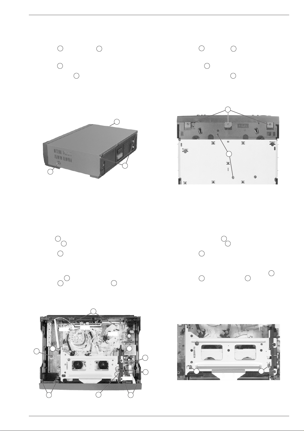
Servicehinweise
1. Entfernen der Gehäuseteile
1.1 Gehäuseoberteil
– 2 Schrauben A und 2 Schrauben B herausdrehen (Fig. 1).
– Gehäuseoberteil abnehmen.
1.2 Frontblende
– 3 Rasthaken C (Fig. 2) auf der Geräteunterseite lösen.
– Frontblende an der Unterseite nach vorne klappen und die Blende
an den oberen Haken D (Fig. 3) aushängen.
Montagehinweis:
– Beim Aufstecken der Frontblende auf den Geräterahmen ist die
Cassettenklappe zu öffnen. Der Cassettenklappenhebel (Pos. 0500,
siehe Seite 6-1) befindet sich dadurch vor der Cassettenklappe in
richtiger Position.
A
B
A
Service Instructions
1. Removing the Cabinet Parts
1.1 Cabinet Top
– Undo 2 screws A and 2 screws B (Fig. 1).
– Remove the cabinet top.
1.2 Front Panel
– Release 3 clamps C (Fig. 2) on the cabinet bottom.
– Turn the lower edge of the front panel towards the front and detach
the panel from the upper clamps D (Fig. 3).
Reassembly:
– When attaching the front panel to the cabinet frame, open the
cassette compartment door. In this way, the door opening lever
(Pos. 0500, see page 6-1) is positioned correctly in front of the
cassette compartment door.
C
I
Fig. 1 Fig. 2
2. Ausbauhinweise
2.1 Laufwerk
– Steckverbindungen (Fig. 3, CN181 / CN201 / CN351) zum Laufwerk
lösen.
– Arretierung E (Fig. 3) des Cassettenschachtes an den beiden
Aussparungen F nacheinander lösen und diesen dabei bis Anschlag nach innen schieben.
– 2 Schrauben G (Fig. 4) herausdrehen.
Hinweis: Der Schraubendreher sollte einen dünnen Schaft haben,
da die linke Schraube schwer zugänglich ist. Sollte kein geeigneter
Schraubendreher zur Verfügung stehen, ist der Cassettenschacht
auszubauen (siehe Kapitel "Laufwerk" Punkt 8.1) und anschließend
die 2 Schrauben G herauszudrehen.
– 2 Schrauben H (Fig. 3) und 2 Schrauben I (Fig. 2) herausdre-
2. Disassembly Instructions
2.1 Drive Mechanism
– Unplug the the plug-in connections (Fig. 3, CN181 / CN201 / CN351)
to the drive mechanism.
– Disengage the locking lever E (Fig. 3) of the cassette mechanism
successively at the two cutouts F and slide the mechanism inwards
to the stop.
– Undo 2 screws G (Fig. 4).
Note: The screwdriver should have a thin shank because access to
the left screw is difficult. If a suitable screwdriver is not available,
remove the cassette compartment mechanism (see "Drive Mecha-
nism", point 8.1) and subsequently undo the 2 screws G.
– Undo 2 screws H (Fig. 3) and 2 screws I (Fig. 2).
– To remove the Drive Mechanism, lift it in horizontal position.
hen.
– Laufwerk waagerecht nach oben herausnehmen.
H
CN181
CN351
CN201
K
O
D
E
O
CN701
K
F
D
G
G
Fig. 3 Fig. 4
GRUNDIG Service 1 - 17
Allgemeiner Teil / General Section GV 29…, GV 9000…, GV 9300…
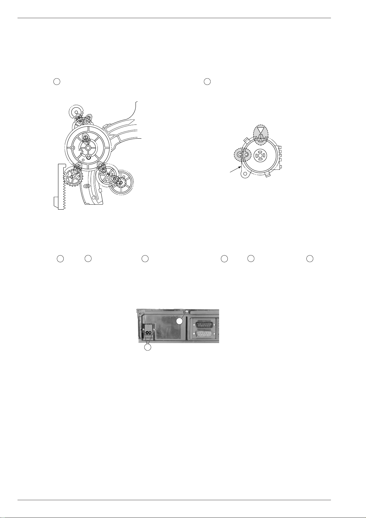
Montagehinweis:
– Der Einbau des Laufwerks muß in der Eject-Position erfolgen.
– Lademotormitnehmer/Schneckenrad in die am Lademotor ange-
gebene Pfeilrichtung so lange drehen, bis sich alle Zahnräder und
Hebel in der in Fig. 5 markierten Position befinden.
– Funktionswahlschalter S8001 durch Drehen des Zahnrades in
die Laufwerkposition Eject bringen (Fig. 5 / 6).
– Beim Aufsetzen des Laufwerks auf die Chassisplatte ist darauf zu
achten, daß die Sensoren für Bandanfang und Bandende in die
Abdeckungen O (Fig. 3) des Cassettenschachtes eintauchen. Das
Laufwerk muß leicht auf der Chassisplatte aufzusetzen sein, damit
die Steckverbindungen zur Chassisplatte richtig kontaktieren.
Reassembly:
– The drive mechanism is to be reassembled in Eject position.
– Turn the loading motor driver/worm gear in the direction of the
arrow on the loading motor until all gear wheels and levers are in
the position shorn in Fig. 5.
– Set the mode switch S8001 to Eject mode by turning the gear
wheel (Fig. 5/6).
– When putting the drive mechanism on to the chassis board take care
of the tape start and tape end sensors. They must plunge into the
covers O (Fig. 3) of the cassette mechanism. It must be possible
to put the drive mechanism easily on the chassis board to ensure
that the connectors to the chassis board are in good contact.
EJECT
S8001
Fig. 5 Fig. 6
2.2 Chassisplatte
– Laufwerk ausbauen (siehe Punkt 2.1).
– Gegebenenfalls Steckverbindung (Fig. 3, CN701) zur Bedieneinheit
lösen.
– je 2 Schrauben K (Fig. 3) / L (Fig. 7) und Schraube M (Fig. 7)
herausdrehen.
– Chassisplatte nach oben vorsichtig herausnehmen.
Sicherheitshinweis
– Nach dem Entfernen des Gehäuserahmens ist die Lötseite des
Netzteils frei zugänglich und damit auch alle lebensgefährlichen
Spannungen. Im Servicefall immer Trenntrafo benutzen.
L
Fig. 7
3. Wichtige Masseverbindungen!
Beim Zusammenbau des Gerätes ist darauf zu achten, daß die
Masseverbindungen zwischen Gehäuseboden und Chassisplatte,
Buchsenplatte und Gehäuseoberteil, Chassisplatte und Laufwerk
sowie Gehäuseboden und Gehäuseoberteil gewährleistet sind.
2.2 Chassis Board
– Remove the drive mechanism (see point 2.1).
– Disconnect the plug-in connections (Fig. 3, CN701) to the keyboard
control unit if necessary.
– Undo 2 screws K (Fig. 3) / L (Fig. 7) each and screw M (Fig. 7).
– Lift the chassis board carefully to remove it.
Safety Precaution:
– After having removed the cabinet frame the solder side of the power
supply board is freely accessible and so are all voltages dangerous
to life. Do not fail to use an isolating transformer during repairs!
M
3. WARNING: Chassis Connections!
When reassembling the machine make sure that the ground connections between the cabinet bottom and chassis board, socket board and
cabinet top, chassis board and drive mechanism, cabinet bottom and
cabinet top are in good order.
4. Durchführen von Messungen
Bei Messungen mit dem Oszilloskop an Halbleitern sollten Sie nur
Tastköpfe mit 10:1 - Teiler verwenden. Außerdem ist zu beachten, daß
nach vorheriger Messung mit AC-Kopplung der Koppelkondensator
des Oszilloskops aufgeladen sein kann. Durch die Entladung über das
Meßobjekt können Bauteile beschädigt werden.
5. Meßwerte und Oszillogramme
Bei den in den Schaltplänen und Oszillogrammen angegebenen
Meßwerten handelt es sich um Näherungswerte!
1 - 18 GRUNDIG Service
4. Carrying out Measurements
When making measurements on semi-conductors with an oscilloscope, ensure that the test probe is set to 10:1 dividing factor. If the
previous measurement was made on AC input, olease note that the
coupling capacitor in the oscilloscope will be charged. Discharge via
the item being checked can damage the components.
5. Measured Values and Oscillograms
The measured values given in the circuit diagrams and oscillograms
are approximates!

GV 29…, GV 9000…, GV 9300… Fehlerdiagnoseprogramm
D
Fehlerdiagnoseprogramm
Die Geräte enthalten ein Fehlerdiagnoseprogramm, das sporadisch
auftretende Fehler erkennt und als Fehlercode speichert. Der Fehlercode und der Code für die Betriebsart, bei der der Fehler aufgetreten
ist, kann abgerufen werden.
Aufruf der Fehlerdiagnoseanzeige
– Im Standby-Betrieb die Taste ı so lange drücken (min. 10s) bis
die Displayanzeige wechselt:
Betriebsstundenzähler
Fehlercode
– Nach ca. 10s wechselt die Anzeige des Displays wieder in den
Standby-Betrieb.
Löschen des Fehlercodes und Betriebsartcodes
– Durch Drücken der Taste "0" während der Anzeige des Fehlercodes
und des Betriebsartcodes sind diese löschbar.
Betriebsartcode
Videokopfausgangssignal
Fehlercodes
"Fehler" gibt den aufgetretenen Fehler an.
"Status" nennt den Betriebszustand nach Auftreten des Fehlers.
"Ursache" gibt Bereiche an, in denen der Fehler zu suchen ist.
Code 00
Fehler: Kein erkennbarer Fehler aufgetreten.
Code 01
Fehler: Kopfscheibenmotor läuft nicht.
Status: Gerät schaltet in den Standby-Betrieb.
Ursache: Kopfscheibenmotor, Kopfscheibenmotor-Ansteue-
Code 02
Fehler: Wickelteller drehen sich nicht.
Status: Gerät schaltet in den Standby-Betrieb.
Ursache: Wickeltellerblockade, Riemen, Wickeltellerdreh-
Code 03
Fehler: Capstanmotor läuft nicht.
Status: Gerät schaltet in den Standby-Betrieb.
Ursache: Capstanmotor, Capstanmotor-Ansteuerung.
Code 04
Fehler: Band kann nicht eingefädelt werden, Ausfädeln funkStatus: Laufwerk fädelt aus, geht in Stellung INITIAL, Gerät
Ursache: Bandführungen der Fädelschlitten verhakt, Lademotor,
Code 05
Fehler: Ein- und Ausfädelfehler.
Status: Laufwerk steht an der Stelle an der der Fehler auftrat,
Ursache: Bandführungen der Fädelschlitten verhakt, Lademotor,
Code 06
Fehler: Cassette kann nicht ausgegeben werden.
Status: EJECT bei eingeschaltetem Gerät: Laufwerk geht in
Ursache: Laufwerk, Cassettenklappe.
Code 07
Fehler: Cassette kann nicht abgesenkt oder ausgegeben
Status: Laufwerk steht an der Stelle an der der Fehler auftrat,
Ursache: Cassette im Schacht verklemmt, Cassettenschacht-
rung, Cassettenband um die Kopfscheibe gewickelt.
moment zu gering.
tioniert.
schaltet in Standby-Betrieb.
Lademotoransteuerung.
Gerät schaltet in Standby-Betrieb.
Lademotoransteuerung.
Stellung STOP.
EJECT bei ausgeschaltetem Gerät (Standby): Laufwerk geht in Stellung INITIAL, Gerät geht in StandbyBetrieb.
werden.
Gerät schaltet in Standby-Betrieb.
mechanik, Cassettenschachtgetriebe.
Code 08/09
Fehler: Fehler beim Durchlauf der einzelnen Laufwerks-
positionen.
Status: Laufwerk steht an der Stelle an der der Fehler auftrat,
Gerät schaltet in Standby-Betrieb.
Ursache: Funktionswahlschalter.
Code 10
Fehler: Capstanmotor dreht sich nicht, Cassette wird nach
dem Einschieben wieder ausgegeben.
Status: Laufwerk geht in EJECT-Stellung.
Ursache: Capstanmotor, Capstanmotor-Ansteuerung.
Code 11
Fehler: Kopfscheibe dreht sich nicht, Cassette wird nach dem
Einschieben wieder ausgegeben.
Status: Laufwerk geht in EJECT-Stellung.
Ursache: Bandtrommeleinheit, Bandtrommel-Ansteuerung.
Code 12
Fehler: Riemenscheibe, Reibkupplung dreht sich nicht, Cas-
sette wird nach dem Einschieben wieder ausgege-
ben.
Status: Laufwerk geht in EJECT-Stellung.
Ursache: Riemenscheibe, Reibkupplung, Riemen, Drehmoment
der Reibkupplung.
Betriebsartcodes
Code Betriebsart
00 Cassette ausgegeben
01 Standby
02 Stop
03 Standbild
04 Aufnahme-Pause
05 Nachvertonung-Pause
06 Einzelbildfortschaltung
07 Zeitlupe
08 Wiedergabe
09 Aufnahme
10 Nachvertonung
11 Wiedergabe (2-fach)
12 Bildsuchlauf vorwärts
13 Bildsuchlauf rückwärts
14 Vorlauf
15 Rücklauf
16 Video-Insert
17 Video-Insert-Pause
18 Audio/Video-Insert
19 Wiedergabe rückwärts (2-fach)
99 sonstiges
Videokopfausgangssignal
Das Fehlerdiagnoseprogramm überwacht auch die Videokopfausgangssignale. Ist das Signal von einem Videokopf oder beiden Videoköpfen zu klein, wird in der Fehlerdiagnoseanzeige ein blinkendes "L"
angezeigt. Prüfen Sie dann die Trackingeinstellung, die eingelegte
Cassette, die Videoköpfe und die Signalwege. Das dabei ausgewertete Hüllkurvensignal der FM-Pakete (VD ENV-Signal) ist an IC301-(85)
meßbar.
4V
0,5V~ 0,95V
0V
Betriebsstundenzähler
In der Fehlerdiagnoseanzeige wird die Betriebsdauer der Kopfscheibe
zweistellig in 100-Stunden-Bereichen angezeigt.
Beispiel: Anzeige 10 = Betriebsstundenbereich 900 bis 999.
GRUNDIG Service 2 - 1
j

Diagnostic Programme GV 29…, GV 9000…, GV 9300…
GB
Diagnostic Programme
These video recorders are provided with a Diagnostic Programme that
identifies occasionally occurring faults and stores the respective error
codes. The error code and the code of the operating mode in which the
error occurred can be called up.
Activating the diagnostic display
– Press and hold down the ı button (at least 10s) until the display
mode changes:
Operating hours meter
Error code
– After about 10s the display is reset to the Standby mode.
Clearing the error code and operating mode code
– These codes can be cleared by pressing the "0" button during the
display of the error code and the operating mode code.
Operating mode code
Video head output signal
Error codes
"Fault" specifies the fault occurred.
"Status" specifies the operating mode to which the VCR changes
"Cause" specifies locations to search for the fault.
Code 00
Fault: There is no abnormality in the mechanism.
Code 01
Fault: Headwheel motor does not rotate.
Status: The VCR switches to Standby mode.
Cause: Headwheel motor, drive to the headwheel motor,
Code 02
Fault: Reels do not rotate.
Status: VCR switches to Standby mode.
Cause: Blockage of reels, reel belt, reel torque is too low.
Code 03
Fault: Capstan motor does not rotate.
Status: VCR switches to Standby mode.
Cause: Capstan motor, drive to the capstan motor.
Code 04
Fault: Tape cannot be loaded. Unloading is ok.
Status: Mechanism unloads, changes to INITIAL position,
Cause: Jammed tape guides of the threading roller units,
Code 05
Fault: Loading and unloading the tape is not possible.
Status: Mechanism is in the position in which the fault oc-
Cause: Jammed tape guides of the threading roller units,
Code 06
Fault: Ejecting the cassette is not possible.
Status: EJECT with the VCR switched on: Mechanism changes
Cause: Mechanism, cassette front door.
Code 07
Fault: Lowering or ejecting the cassette is not possible.
Status: Mechanism is in the position in which the fault oc-
Cause: Cassette jammed within the cassette compartment,
when the fault occurs.
cassette tape wound around the headwheel.
VCR changes to Standby mode.
loading motor, drive to the loading motor.
curred, VCR switches to Standby mode.
loading motor, drive to the loading motor.
to STOP position.
EJECT with the VCR switched off (Standby): Mechanism changes to INITIAL position, VCR switches to
Standby mode.
curred, VCR switches to Standby mode.
cassette compartment mechanism, cassette com-
partment gears.
Code 08/09
Fault: Fault when sequentially switching through the indi-
vidual mechanism mode positions.
Status: Mechanism is in the position in which the fault oc-
curred, VCR switches to Standby mode.
Cause: Mode switch
Code 10
Fault: Capstan motor does not rotate, cassette is ejected
when having inserted it.
Status: Mechanism changes to the EJECT position.
Cause: Capstan motor, drive to the capstan motor.
Code 11
Fault: Headwheel does not rotate, cassette is ejected when
having inserted it.
Status: Mechanism changes to the EJECT position.
Cause: Tape drum assy, tape drum drive.
Code 12
Fault: Pulley, friction clutch does not rotate, cassette is
ejected when having inserted it.
Status: Mechanism changes to the EJECT position.
Cause: Pulley, friction clutch, belt, torque of friction clutch.
Operating mode codes
Code Operating mode
00 Cassette Out
01 Standby
02 Stop
03 Still
04 Record-Pause
05 Dubbing-Pause
06 Frame Advance
07 Slow
08 Play
09 Record
10 Dubbing
11 Play (2x speed)
12 Picture Search Forward
13 Picture Search Reverse
14 Fast Forward
15 Reverse
16 Video Insert
17 Video Insert-Pause
18 Audio/Video Insert
19 Reverse Play (2x speed)
99 others
Video head output signal
The Diagnostic Programme is also responsible for monitoring the
video head output signals. If the signal of one or of the two video heads
is too low, the letter "L" will flash in the diagnostic display. In this case,
check the tracking position, the inserted cassette, the video heads and
the signal paths. The evaluated envelope signal of the FM packages
(VD ENV-Signal) can be measured at IC301-(85).
4V
0.5V~ 0.95V
0V
Operating hours meter
The operating hours of the headwheel are indicated in the diagnostic
display as two-digit numbers by hundreds.
Example: Indication 10 = operating hours ranging from 900 to 999.
2 - 2 GRUNDIG Service
k
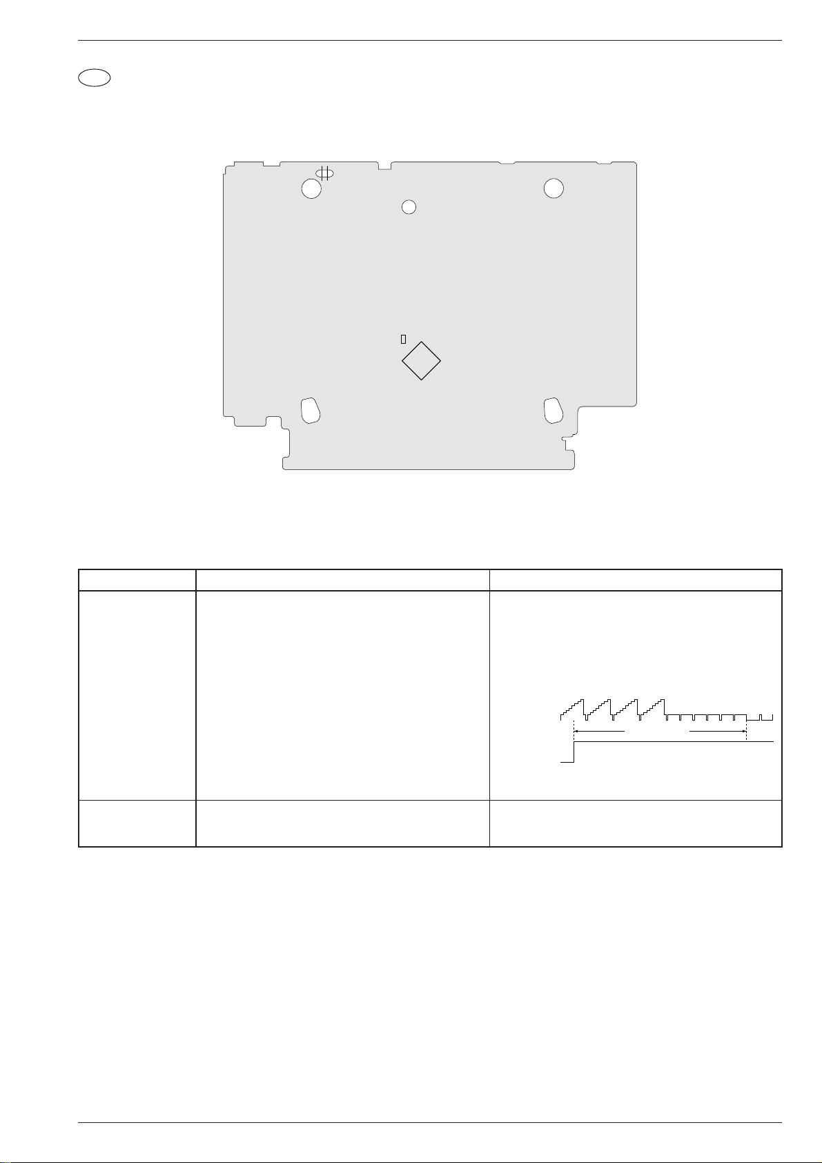
GV 29…, GV 9000…, GV 9300… Abgleichvorschriften
D
Abgleichvorschriften
1. Chassisplatte
Ansicht von der Lötseite
TP182
TP183
C3016
IC301
Meßgeräte / Meßmittel: Zweikanal-Oszilloskop mit Tastköpfe 10:1, Farbgenerator, Testcassette, Videocassette von Markenhersteller
Servicearbeiten nach Austausch …
… der Bandtrommel: Abgleich Nr. 1, 2
… des IC304: Abgleich Nr. 1, 2
Abgleich Vorbereitung Abgleichvorgang
1. KopfradLagengeber
Oszilloskop; Kanal 1 (Triggerung):......................... TP183
Kanal 2: ................................... Buchse Euro-AV1-(19)
Testcassette wiedergeben.
Taste K sofort nach Erscheinen des Wiedergabe-Bildes
3 Mal kurzzeitig antippen. Anschließend erfolgt der automatische Abgleich.
•Automatischer Abgleich: Der Abgleichvorgang wird im
Display angezeigt. Dabei läuft der Zähler von "P: 0:01" bis
maximal "P: 2:55". Beim eingestellten Wert bleibt der
Zähler stehen und ist manuell abgleichbar.
•Manueller Abgleich: Mit den Tasten Ü oder * ist der
Kopfumschaltimpuls auf 6,5 ±0,5 Zeilen vor den VertikalSynchronimpulsen einzustellen.
Kanal 2:
1V/div 50µs/div
Video-Ausgang
Kanal 1:
2V/div 50µs/div
Kopfumschaltimpuls
Testbetrieb verlassen durch Drücken der Taste u. Im Display erscheint kurzzeitig "P:– : –".
2. Standbild optimieren
FBAS-Signal an der EURO-AV1-Buchse einspeisen und
im Standardplay-Betrieb aufzeichnen.
Mit den Tasten C / D das Standbild nach subjektiv
bestem Eindruck einstellen.
Eigenaufnahme wiedergeben und Taste Ó drücken.
6.5 ±0.5H (Zeilen)
V-Sync.
GRUNDIG Service 3 - 1
j
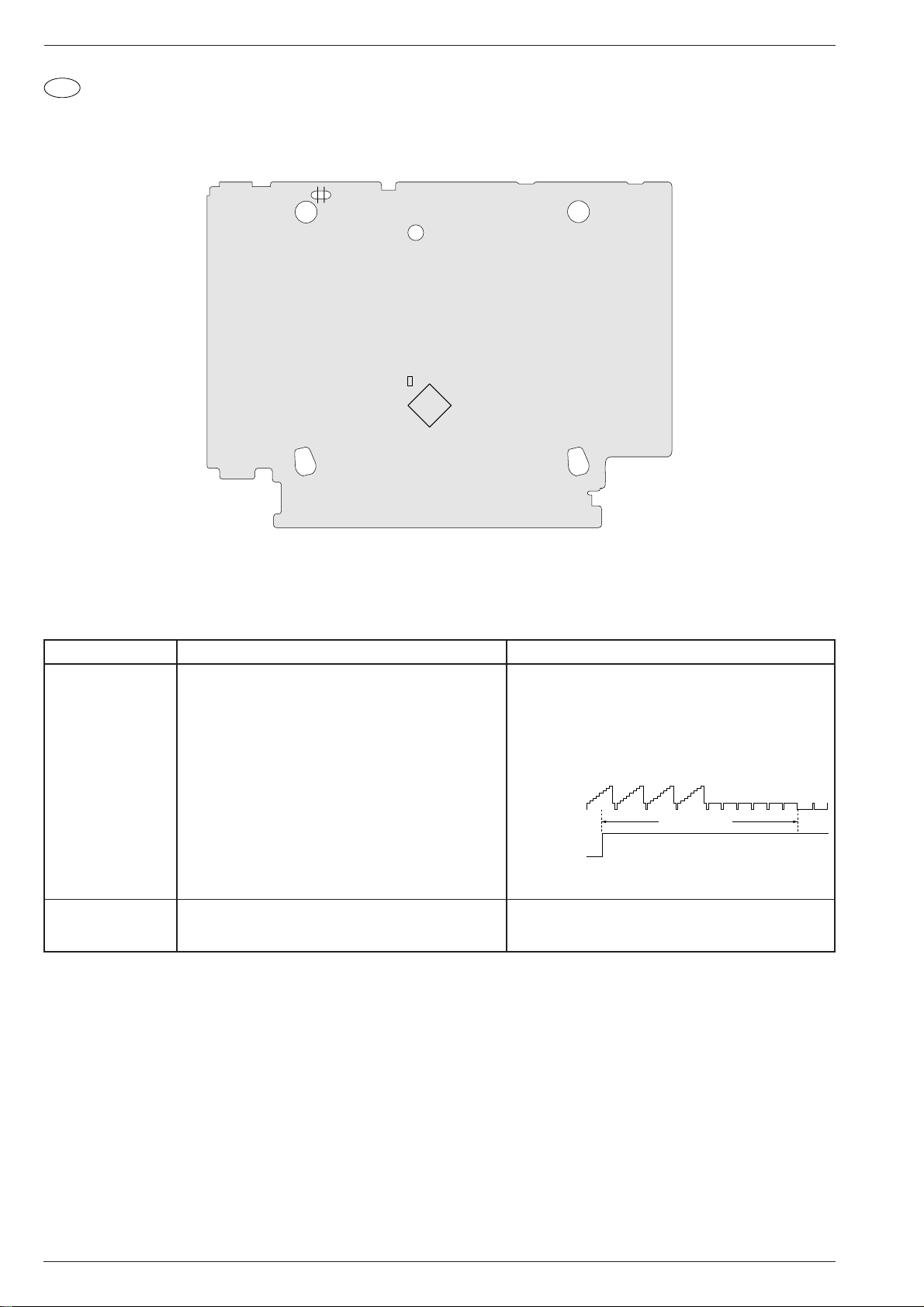
Adjustment Procedures GV 29…, GV 9000…, GV 9300…
GB
Adjustment Procedures
1. Chassis Board
View of Solder Side
TP182
TP183
C3016
IC301
Test equipment / aids: Two-channel oscilloscope with 10:1 probes, voltmeter, colour generator, test cassette, branded video cassette
Service works on replacement of …
… the tape drum: Adjustment No. 1, 2
… IC304: Adjustment No. 1, 2
Adjustment Preparation Adjustment Procedure
1. Headwheel
Position Indicator
Oscilloscope: Channel 1 (trigger):.......................... TP183
Channel 2: ................................. Euro-AV1-(19) socket
Play test cassette.
When the playback picture appears touch the K button
three times immediately. The automatic adjustment mode
will start.
•Automatic adjustment: The adjustment process is
indicated on the display. The meter counts from "P: 0:01"
to maximum "P: 2:55". The meter will stop at the set value.
The value can then be adjusted manually.
•Manual adjustment: Use the buttons Ü or * to set the
head switching pulse to 6.5 ±0.5 lines before the vertical
sync pulses.
Channel 2:
1V/div 50µs/div
Video output
Channel 1:
2V/div 50µs/div
Head switching pulse
6.5 ±0.5H (lines)
Press button u to leave the test mode. The indication
"P:– : –" appears for a short time on the display.
2. Still Picture
Optimisation
Feed a CCVS signal into the EURO-AV1 socket and
record it in Standardplay mode.
With buttons C / D set the still picture according to your
best personal impression.
Play back this recording and press button Ó .
V-sync
3 - 2 GRUNDIG Service
k

GV 29…, GV 9000…, GV 9300… Platinenabbildungen und Schaltpläne / Layout of PCBs and Circuit Diagrams
Reference
Oscillograms....4-14
AD-A................4-29
CP-1 ................4-11
MC-A ...............4-19
PW-A...............4-17
SY-A................4-18
TB-1.................4-31
TC-A................4-29
TM-1................4-22
TM-A................4-23
VA-A................4-25
Platinenabbildungen und Schaltpläne
Layout of PCBs and Circuit Diagrams
Verdrahtungsplan
Wiring Diagram
GV 29…, GV 9000…, GV 9300… Platinenabbildungen und Schaltpläne / Layout of PCBs and Circuit Diagrams
(GV29)
(GV9000/9300)
GV29
GV9000/9300
GV29
GV9000/9300
ONLY FOR
4 HEAD
ONLY FOR
2 HEAD
GRUNDIG Service 4 - 1 GRUNDIG Service 4 - 2
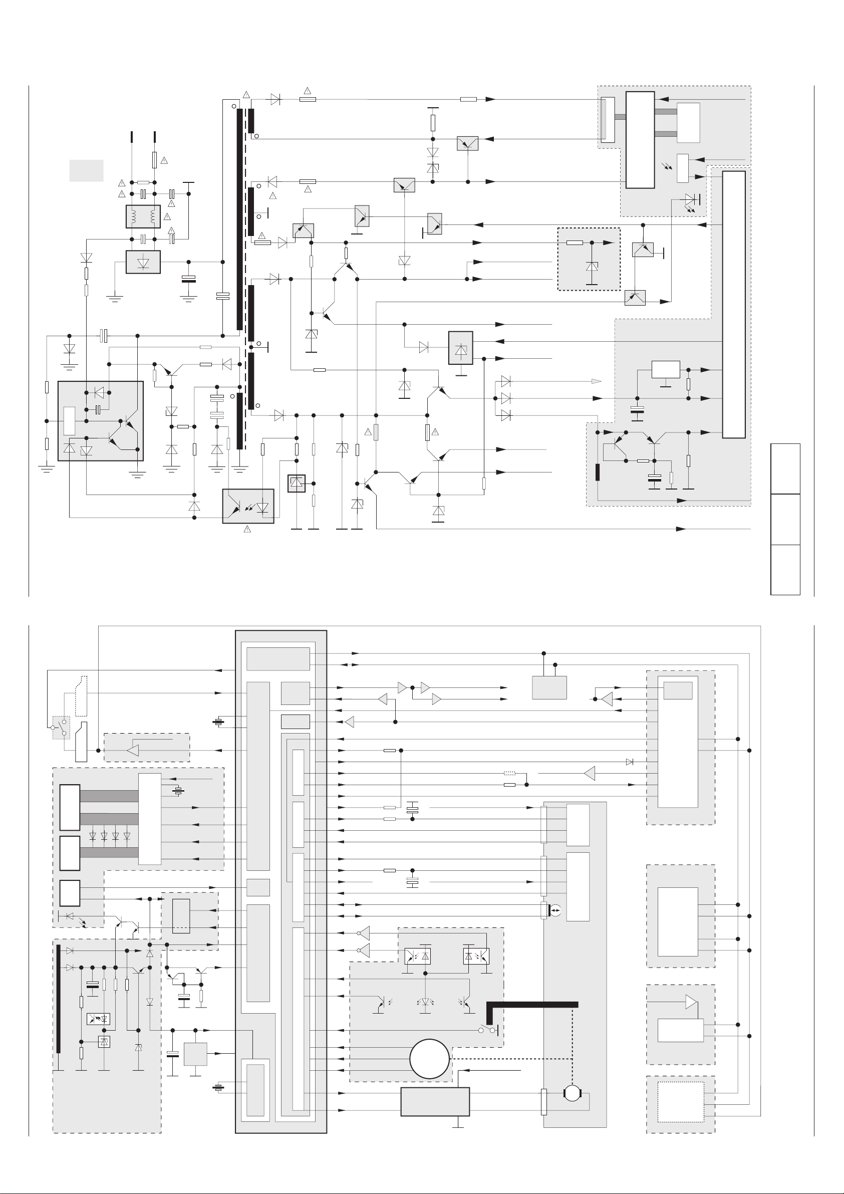
4 - 3 GRUNDIG Service 4 - 4 GRUNDIG Service
Start
SWD (PS) 37V
POWER CTL
SWD 5V(AD)
SWD 5V
SWD (PS) -23V
Life
Ground
HEATER +
HEATER -
CHASSIS
C5010
D5001
F5001
DELAY
CONTROL
OVERLOAD
ALWAYS 5.8V (LED)
SWD (PS) 12V
SWD 9V
SWD (PS) 13V (MC)
(POWER SAVE) PS CTL
Overvoltage
Protection
SAVE MODE
Feed Back
CONTROL
IC501
IC511
D5013
D5019
D5012
D5016D5015
Q5002
523
1
467
D5002
D5014
D5101
D5106
D5102
D5110
Q5103
Q5114
PR512
SWD (PS) 5V
Q5102
(PS) = Power Save
D5108
D5111
D5107
Q5101
Q5104
Q5120
Q5116
D5112
Q5115
Q5112
Q5111
D5103
R5110
D5104
R5120
Q5113
Q5110
D5115
D5109
D5116
D5105 PR511
SWD (PS) 13V
C5012
C5014/16
C5013
D5011
6,8V
R5121
-23V
+13V
+5,8V
97
Low Power = H
Stand By; On = L
(Low Power) Stand By = L
On = H
POWER SAVE
LED
C3017
25
IR
RR701
Clock
Keyboard
DISPLAY
5
R5015
R5014
IC512
PR513
Q5117
ALWAYS 5V(2)
D5120
D5119
FLD DRIVE
KEY SCAN
ALWAYS 5V (FL)
POWER DOWN
BACK UP 5V
RESET
ALWAYS 5V (IR)
ALWAYS
5V (IR)
ALWAYS 5V(FL)
IC 301
IC305
10
80
36; 42
System Controller
D5118
ALWAYS 5V(1)
6,2V
5,6V
ca.5.6V
5,6V
Q3010 Q3009
C3526
L3065
IC701
TM-A
SY-A
PW-A
33V
D3401
R3309
SY-A
D5101
D5013
IC511
RESET
REMOCON
POWER
SAVE
Display
Keyboard
Remote
Control
RC
Power-Supply
Control
POWER DOWN
POWER
CTL
Clock / Date
Timer
Tuning- & System Control
Key 0…3
IC301
5
97
36; 42
80
25
10
+13V
40
41
37
38
RR701
96AV CTL
8
SWD (PS)12V
Q1008/1009
SEGt a…l (Anoden)
GRID 1…9 G
DIODE OPTION
D5102
PW-A
Back
Up
FLD DRIVE (IC701)
& KEY SCAN
Euro-AV 1
ALWAYS 5V (FL)
FLD DATA IN
FLD DATA OUT
FLD CLK
25
18
24
23
TM-A
15
16
14
27
22
FLD CS
ALWAYS 5V (IR)
ca. 6V Q5120
Q5117
Q5116
9
M
MECHANISM
MODE
SWITCH
11
12
8
Lift
SAFETY/FL SW
D8001D8002 D8003
89
88
3
4 Q3007
Q3008
PC802
PC801
TAPE END
TAPE START
SUPPLY TAKE OFF
75
74
C-FG
C-VS33
67
68 FG OUT
D-FG
D-PG
Drum Frequency Generator
Drum Phase Generator
Capstan Frequency Generator
Capstan Velocity Speed
65
66
CTL+
CTL-
20 MC-FR
Motor Control - Foreward / Reverse
34 D-VS Drum Velocity SpeedD-VS
VLOCK / QVD
RF SWP
ENV DET (Autotrack)
YC AD MUTE
73
ALWAYS 5V (IR)
ALWAYS 5V (2)
OSD
SYNC
SEP
Seriell Interface
& I
2
C-Bus
VA-A
TC-A
IC141
VPS / PDC
Tuner
Modulator
IF-Amplifier
PLL-Demod.
SIF-Amplifier
FM-Demod.
SY-A
IC861
Video & Audio
I / O-Selector
(2 Euro-AV with
decoder only
MECHANISM
17
50
49
47
D1001
C SYNC
VA-A
EEPROM
IC304
18
25
26
8
Euro-AV 2
FSS IN
LO-MOTOR -
8
6
(ML-S)
LO-MOTOR +
8/9
CTL HEAD
(ML-D)
Y / C & audio processor
with CCD, with input- output
selector and headamplifier
IC101
MC-A
S8001S8002
85
99
60
23
24
Drum Control Head Control
Capstan Motor Driver
Drum
Motor
Driver
Deck Control
DATA
CLK
SWD (PS)13V; SWD 5V
SWD (PS)13V
SWD (PS)13V
Loading Motor Drive
IC302
CN352
CN201
CN801
CN351
IC5106
IC5120 IC5118
SY-A
93
10
11
Q1007
FSC
66
Q1006
CCD
49
24
23
26
28
29
PB ENV (PB FM)
TP182
Q1010
VD (TO MCOM)
VD (from MC)
95
Q3062/3065
Q3061
REC H 30
28
(COIN)
62
74
SWD 5V
Capstan Control
2
10
3
4
1
H AMP SW
PB L
Q8604
Q8605
44
16
16
VD OUT (AV)
Q1012
Q1001
VD OUT (CV)
98
ROTARY
(NP/LP)
(Head Switch Pulse)
VD
(FROM MCOM)
Q1401
4
Platinenabbildungen und Schaltpläne / Layout of PCBs and Circuit Diagrams GV 29…, GV 9000…, GV 9300… Platinenabbildungen und Schaltpläne / Layout of PCBs and Circuit Diagrams GV 29…, GV 9000…, GV 9300…
Blockschaltplan – Netzteil
Block Circuit Diagram – Power Supply
Reference
Oscillograms....4-14
AD-A................4-29
CP-1 ................4-11
MC-A ...............4-19
PW-A...............4-17
SY-A................4-18
TB-1.................4-31
TC-A................4-29
TM-1................4-22
TM-A................4-23
VA-A................4-25
Blockschaltplan / Block Circuit Diagram – Digital
 Loading...