


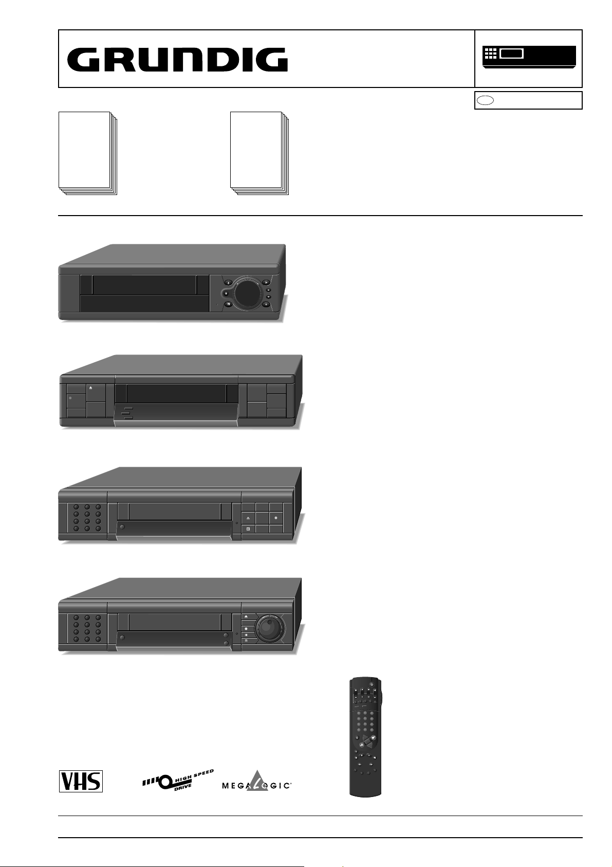
GV 464
Service
Manual
Sach-Nr./Part No.
72010-519.40
Zusätzlich erforderliche Unterlagen
für den
Komplettservice:
Additionally required
Service Manuals for
the Complete Service:
Service
Manual
Sicherheit
Safety
Sach-Nr./Part No.
72010-800.00
SERVICE MANUAL
GV 500 …, GV 510 …, GV 530 …
GV 5095 … / Barcelona
SE 5102 …, SE 5104 …
GV 500 SV (77400-602.51 / G.ME 0700)
GV 500 SV/1 (77400-615.51 / G.ME 0600)
GV 500 GB (77400-625.51 / G.ME 0800 GB)
GV 510 SV (77400-604.51 / G.ME 1600)
GV 530 SV (77400-639.51 / G.ME 5900)
GV 530 SV/1 (77400-626.51 / G.ME 2000)
VIDEO
D
Btx * 32700
#
GV 5050 …
GV5395 … / Florenz
(77400-640.51 / G.ME 2010)
&
%
1 2 3
4 5 6
7 8 9
SV0AV
1 2 3
4 5 6
7 8 9
SV0AV
GV 5050 SV (77400-627.51 / G.ME 0500)
GV 5050 SV/1 (77400-631.51 / G.ME 4100)
ii
II
t
TIMER
ON/OFF
8
CHECK
CLEAR
ii
GV 5095 SV / Barcelona (77400-663.51 / G.ME 5700)
GV 5095 SV/1 / Barcelona (77400-644.51 / G.ME 1100)
SE 5102 SV (77400-635.51 / G.ME 2500)
TIMER
ON / OFF
ii
&
II
e
%
ii
GV 5395 SV / Florenz (77400-658.51 / G.ME 5800)
GV 5395 SV/1 / Florenz (77400-643.51 / G.ME 2300)
SE 5104 SV (77400-636.51 / G.ME 2600)
e
TIMER
ON / OFF
%
%
DAY START
STOP
PROG.
ON/OFF
SP/LP
CLEAR
SV/V+
SET/CHECK
TIMER
2
3
1
5
6
4
8
9
7
0
AVVPT
RP500 (75988-010.71)
+
+
OK
-
I
G
N
N
I
D
K
E
C
X
A
R
T
IN
D
E
E
S
X
A
R
M
E
A
X
R
E
K
D
I
N
PAL / SECAM OST
Änderungen vorbehalten Printed in Germany Service Manual Sach-Nr. 72010-519.40
Subject to alteration VK 21/1 0695 Service Manual Part No. 72010-519.40

Allgemeiner Teil / General
Es gelten die Vorschriften und Sicherheitshinweise
gemäß dem Service Manual "Sicherheit", Sach-Nummer 72010-800.00, sowie zusätzlich die eventuell
abweichenden, landesspezifischen Vorschriften!
D
Inhaltsverzeichnis
Seite
Allgemeiner Teil................................... 1-1…1-30
Geräteübersicht .............................................................................. 1-3
Meßgeräte / Meßmittel.................................................................... 1-5
Technische Daten ........................................................................... 1-5
Bedienelemente .............................................................................. 1-7
Servicehinweise ............................................................................ 1-21
Codeaufkleber............................................................................... 1-24
Service- und Sonderfunktionen..................................................... 1-25
Beschreibungen.................................... 2-1…2-12
Netzteil (OSM…)............................................................................. 2-1
Chassisplatte (OFB2)...................................................................... 2-3
• Laufwerksteuerung / Deck-Elektronik (DE) .................................. 2-3
• Empfangseinheit (FV) .................................................................. 2-5
• IN/OUT, VPS (IO) ........................................................................ 2-6
• Video/Chroma (VS) ...................................................................... 2-7
• Standardton / Audio Linear (AL) .................................................. 2-9
Chassisplatte II (OSIO) ................................................................. 2-10
• Ablaufsteuerung (CO) ................................................................ 2-10
• Follow TV (IO) ............................................................................ 2-10
• OSD ........................................................................................... 2-11
Bedieneinheit (ODCG…) .............................................................. 2-11
Abgleich .................................................. 3-1…3-3
Netzteil (OSM…)............................................................................. 3-1
Chassisplatte (OFB2)...................................................................... 3-1
• Laufwerksteuerung / Deck-Elektronik (DE) .................................. 3-1
• Empfangseinheit (FV) .................................................................. 3-2
• Video/Chroma (VS) ...................................................................... 3-2
• Standardton / Audio Linear (AL) .................................................. 3-2
Chassisplatte II (OSIO) – OSD ....................................................... 3-3
Bedieneinheiten (ODCG…) ............................................................ 3-3
Platinenabbildungen
und Schaltpläne ................................... 4-1…4-58
Abkürzungen................................................................................... 4-1
Verdrahtungsplan............................................................................ 4-3
Blockschaltpläne (Analog / Digital) ................................................. 4-5
Netzteil (OSM…)........................................................................... 4-11
Laufwerkplatte – Sensoreneinheit................................................. 4-19
Chassisplatte (OFB2).................................................................... 4-15
• Laufwerksteuerung / Deck-Elektronik (DE) ................................ 4-21
• Empfangseinheit (FV) ................................................................ 4-23
• IN/OUT, VPS (IO) ...................................................................... 4-26
• Video/Chroma (VS) .................................................................... 4-29
• Standardton / Audio Linear (AL) ................................................ 4-32
Chassisplatte II (OSIO) ................................................................. 4-33
• Ablaufsteuerung (CO) ................................................................ 4-34
• OSD ........................................................................................... 4-35
• Follow TV, IN/OUT II (IO)........................................................... 4-36
Kopfverstärkerplatte (OHA)........................................................... 4-37
• Kopfscheibenmotoransteuerung ................................................ 4-38
• Kopfverstärker............................................................................ 4-39
Bedieneinheit (ODCG1) ................................................................ 4-41
Bedieneinheit (ODCG3 / ODCG31) .............................................. 4-45
Bedieneinheit (ODCG4 / ODCG41) .............................................. 4-49
Bedieneinheit (ODCG5) ................................................................ 4-53
Oszillogramme .............................................................................. 4-57
Laufwerk .............................................. 5-1…5-12
Meßgeräte / Meßmittel.................................................................... 5-1
Servicehinweise .............................................................................. 5-2
Auswechseln von Laufwerksteilen .................................................. 5-3
Einstellungen ................................................................................ 5-10
Explosionszeichnungen
und Ersatzteilliste ............................... E-1…E-48
The regulations and safety instructions shall be valid
as provided by the "Safety" Service Manual, part
number 72010-800.00, as well as the respective
national deviations.
GB
Table of Contents
Page
General ................................................. 1-1…1-30
Video Recorder Overview ............................................................... 1-3
Test Equipment / Aids..................................................................... 1-5
Specifications.................................................................................. 1-5
Operating Elements ...................................................................... 1-14
Service Instructions....................................................................... 1-21
Code Labels.................................................................................. 1-24
Service and Special Functions...................................................... 1-25
Descriptions.......................................... 2-1…2-12
Power Supply (OSM…)................................................................... 2-1
Family Board (OFB2) ...................................................................... 2-3
• Deck Control / Deck Electronic (DE) ............................................ 2-3
• Frontend (FV)............................................................................... 2-5
• IN/OUT, VPS (IO) ........................................................................ 2-6
• Video/Chroma (VS) ...................................................................... 2-7
• Standard Sound / Audio Linear (AL) ............................................ 2-9
Family Board II (OSIO) .................................................................2-10
• Sequence Control (CO) ............................................................. 2-10
• Follow TV (IO) ............................................................................ 2-10
• OSD ........................................................................................... 2-11
Keyboard Control Unit (ODCG…)................................................. 2-11
Adjustment Procedures......................... 3-4…3-6
Power Supply (OSM…)................................................................... 3-4
Family Board (OFB2) ...................................................................... 3-4
• Deck Control / Deck Electronic (DE) ............................................ 3-4
• Frontend (FV)............................................................................... 3-5
• Video/Chroma (VS) ...................................................................... 3-5
• Standard Sound / Audio Linear (AL) ............................................ 3-5
Family Board II (OSIO) – OSD........................................................ 3-6
Keyboard Control Units (ODCG…) ................................................. 3-6
Layout of the PCBs
and Circuit Diagrams.......................... 4-1…4-58
Abbreviations .................................................................................. 4-1
Wiring Diagram ............................................................................... 4-3
Block Circuit Diagrams (Analog / Digital) ........................................ 4-5
Power Supply (OSM…)................................................................. 4-11
Tape Deck Sensor Panel .............................................................. 4-19
Family Board (OFB2) .................................................................... 4-15
• Deck Control / Deck Electronic (DE) .......................................... 4-21
• Frontend (FV)............................................................................. 4-23
• IN/OUT, VPS (IO) ...................................................................... 4-26
• Video/Chroma (VS) .................................................................... 4-29
• Standard Sound / Audio Linear (AL) .......................................... 4-32
Family Board II (OSIO) ................................................................. 4-33
• Sequence Control (CO) ............................................................. 4-34
• OSD ........................................................................................... 4-35
• Follow TV, IN/OUT II (IO)........................................................... 4-36
Head Amplifier Board (OHA)......................................................... 4-37
• Headwheel Motor Control .......................................................... 4-38
• Head Amplifier ........................................................................... 4-39
Keyboard Control Unit (ODCG1) .................................................. 4-41
Keyboard Control Unit (ODCG3 / ODCG31)................................. 4-45
Keyboard Control Unit (ODCG4 / ODCG41)................................. 4-49
Keyboard Control Unit (ODCG5) .................................................. 4-53
Oscillograms ................................................................................. 4-57
Drive Mechanism................................. 5-1…5-12
Test Equipment / Aids..................................................................... 5-1
Service Instructions......................................................................... 5-2
Replacement of Tape Deck Components ....................................... 5-3
Adjustments .................................................................................. 5-10
Exploded Views and
Spare Parts List .................................. E-1…E-48
1 - 2 GRUNDIG Service
Allgemeiner Teil / General
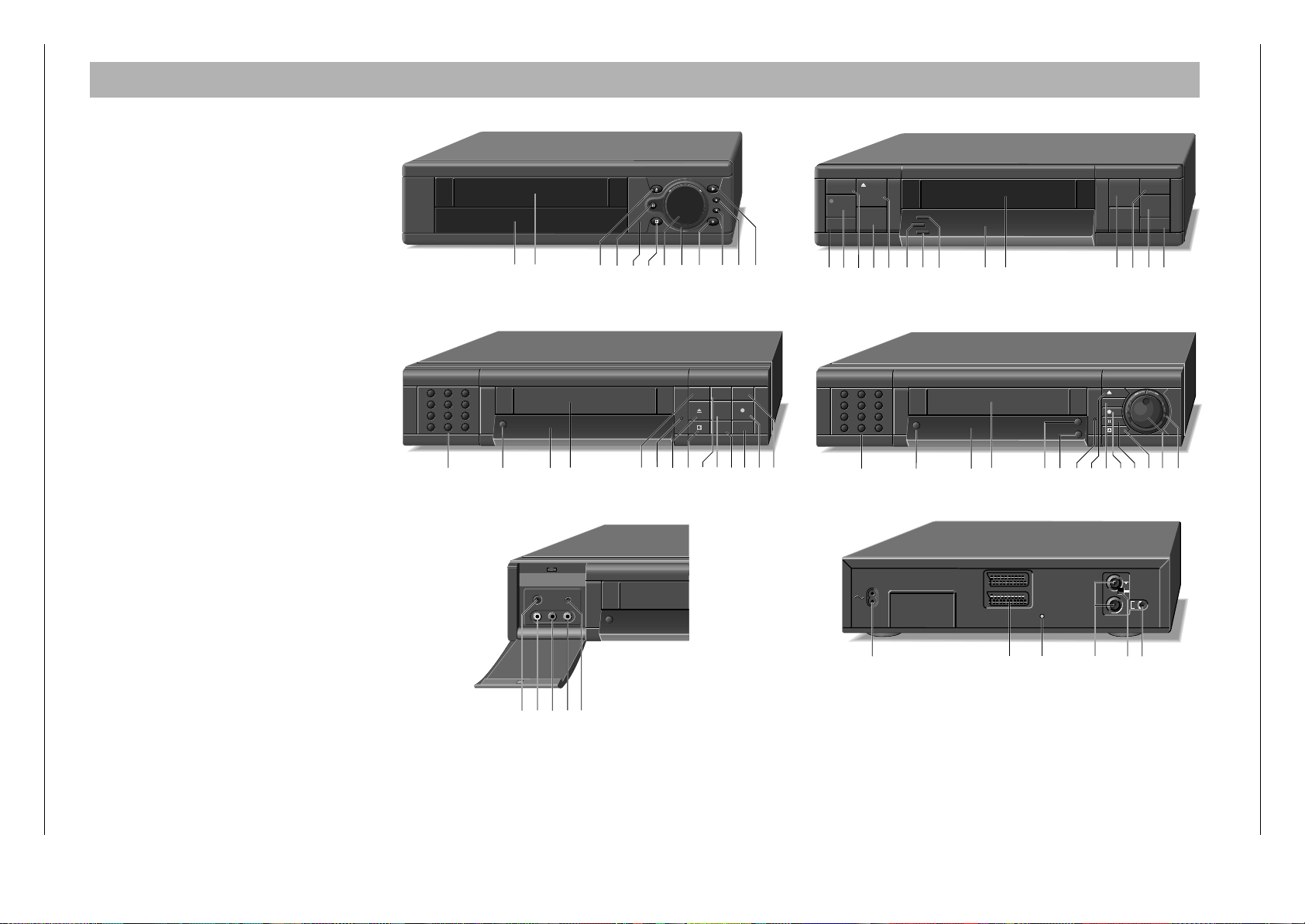
Geräteübersicht / Video Recorder Overview
Allgemeiner Teil / General
Allgemeiner Teil / General
S./P 4-11Netzteil / Power Supply (OSM42)27599-003.13
S./P 4-11Netzteil / Power Supply (OSM43)27599-003.12
S./P 4-11Netzteil / Power Supply (OSM41)27599-003.11
S./P 4-19Laufwerkplatte-Sensoreneinheit / Tape Deck Sensor Panel75988-001.18
Bausteinübersicht
Table of Moduls
S./P 4-15
S./P 4-21
S./P 4-23
S./P 4-26
S./P 4-29
S./P 4-32
Chassisplatte / Family Board (OFB2)
· Laufwerksteuerung / Deck Control (DE)
· Empfangseinheit / Frontend (FV)
· IN/OUT (IO)
· Video/Chroma (VS)
· Standardton / Standard Sound (AL)
S./P 4-33
Chassisplatte II / Family Board II (OSIO)
S./P 4-37
S./P 4-34
S./P 4-35
S./P 4-36
· Ablaufsteuerung / Sequence Control (CO)
· OSD
· Follow TV, IN/OUT (IO)
S./P 4-38
Kopfverstärkerplatte / Head Amplifier Board (OHA)
· Kopfscheibenmotoransteuerung / Headweel Motor Control
S./P 4-41Bedieneinheit / Keyboard Control Unit (ODCG1)27599-002.41
S./P 4-39
· Kopfverstärker / Head Amplifier
S./P 4-48Bedieneinheit / Keyboard Control Unit (ODCG31/S)27599-002.44
S./P 4-53Bedieneinheit / Keyboard Control Unit (ODCG5)27599-002.43
S./P 4-45Bedieneinheit / Keyboard Control Unit (ODCG3)27599-002.42
S./P 4-49Bedieneinheit / Keyboard Control Unit (ODCG41)27599-002.47
S./P 4-48Bedieneinheit / Keyboard Control Unit (ODCG31/JS)27599-002.46
S./P 4-49Bedieneinheit / Keyboard Control Unit (ODCG4)27599-002.45
Feature-Übersicht
Table of Features
S./P 4-45Synchro-Edit Platte / Board (OES)75988-028.45
GV 500 SV
GV 500 SV/1
GV 500 GB
GV 510 SV
GV 530 SV
GV 530 SV/1
GV 5050 SV
GV 5050 SV/1
GV 5095 SV
GV 5095 SV/1
GV 5395 SV
GV 5395 SV/1
SE 5102 SV
SE 5104 SV
27599-001.72
27599-001.70
27599-001.69
27599-001.67
27599-001.64
27599-001.63
27599-001.62
27599-001.61
27599-001.60
27599-001.58
• •
• •••••••••
• •••••••••••••
75988-028.12
• •••••••••••••
• •
• •
•
•
•
•
• •
• •
•
• •
•
27599-004.06
• • ••••• •
• ••• •
Mikrofonbuchse / Micro Jack
"SYNCHRO-EDIT"-Buchse / Socket (ø 2,5mm Klinkenbuchse / mini-minijack)
LINE/CV-Buchsen / Sockets
"PAY-TV"-Buchse / Socket (EURO-AV2)
Piezo-Ton / Sound
VISS (automatisches und manuelles Setzen/Lšschen / automatic and manuel setting/erasure)
Nachvertonung / Dubbing
Kindersicherung / child lock
OSD
Teletext "DOS"
99 Programme, EURO-AV1, EURO-AV2/PAY-TV
VIDEO +
SHOW VIEW
6 Timer
PDC
VPS
Follow TV
Megalogic
Energiesparend / Low Power
4 Kopf / Head (Standard play / Longplay)
3 Kopf / Head (Standard play)
2 Kopf / Head (Standard play)
NTSC-Wiedergabe / NTSC Playback
CCIR, I - PAL
CCIR, B/G/H - PAL
• •••••••••••••
• • •••••••••••
• •••••
• •••
• • •••••••••••
• • ••••• •
• •••••••••••
• •••••••••••
• •••••••••••••
• •••••••••••••
• •••••••••••••
• •••••••••••••
• •••••••••••••
• •••••••••••••
• • • • • •
•
•
•
• •
• •
•
• ••• •
•
• ••• •
• •
• • •
• • •
• • •
• •••••••••••••
• ••• •
• •••••••
• •••••
GV 500 SV
GV 500 SV/1
GV 500 GB
GV 510 SV
GV 530 SV
GV 530 SV/1
GV 5050 SV
GV 5050 SV/1
GV 5095 SV
GV 5095 SV/1
• • •
GV 5395 SV
GV 5395 SV/1
SE 5102 SV
SE 5104 SV
27599-004.09
27599-004.07
GRUNDIG Service 1 - 3
GRUNDIG Service 1 - 4

Allgemeiner Teil / General
Allgemeiner Teil / General
Meßgeräte / Meßmittel
Regeltrenntrafo Farbgenerator
Zweikanaloszilloskop Tongenerator
Digitalmultimeter Stabilisiertes Netzgerät
Millivoltmeter Frequenzzähler
Beachten Sie bitte das Grundig Meßtechnik-Programm, das Sie unter
folgender Adresse erhalten:
Grundig electronics GmbH
Würzburger Str. 150
D-90766 Fürth/Bay.
Tel. 0911/703-0
Telefax 0911/703-4479
Sach-Nr.
Testcassette..................................................................9.27540-1011
Testcassette (HiFi) ........................................................9.27540-1016
Drehmomentmesser 600gf-cm..................................... 75987-262.72
Adapter .........................................................................75987-262.73
Einstellschraubendreher ...............................................75987-262.80
Bandzug-Einstellgriff und -stift ..................................... 75988-002.27
Kopfscheibenabzieher ..................................................75988-002.37
Nylonhandschuhe .........................................................handelsüblich
Tentelometer .................................................................handelsüblich
Diese Meßmittel können Sie über die Serviceorganisation beziehen.
Wir weisen jedoch darauf hin, daß es sich hierbei z.T. um Meßmittel
handelt, die am Markt bereits eingeführt sind.
Testcassette Sach-Nr. 9.27540-1011
• Farbtestbild mit Dropout-Einblendung
• 6,3kHz-Senkrecht-Vollspuraufzeichnung und Bezugspegel 333Hz
in dreiminütigem Wechsel.
Testcassette (HiFi) Sach-Nr. 9.27540-1016
• Farbtestbild mit Dropout-Einblendung
• Längsspur-Ton: 6,3kHz und 333Hz
• FM-Ton: 1kHz Vollpegel (± 50kHz Hub)
Video-Lehrfilm Sach-Nr. 72007-744.81
• Laufwerk "High Speed Drive"
Test Equipment / Aids
Variable isolating transformer Colour generator
Dual channel oscilloscope AF Generator
Digital multimeter Stabilized power supply
Millivoltmeter Frequency counter
Please note the Grundig Catalog "Test and Measuring Equipment"
obtainable from:
Grundig electronics GmbH
Würzburger Str. 150
D-90766 Fürth/Bay.
Tel. 0911/703-0
Telefax 0911/703-4479
Part no.
Test cassette.................................................................9.27540-1011
Test cassette (HiFi) .......................................................9.27540-1016
Torquemeter 600gf-cm..................................................75987-262.72
Adapter .........................................................................75987-262.73
Adjustment screw driver................................................75987-262.80
Tape tension adjustment tool - handle and - pin .......... 75988-002.27
Headwheel extractor .....................................................75988-002.37
Nylon gloves ....................................................... commonly available
Tentelometer ....................................................... commonly available
You can order these test equipments from the Service organization.
We refer to you that these test equipments are already obtainable on
the market.
Test cassette Part no. 9.27540-1011
• Colour test pattern with dropout recording
• 6.3kHz vertical full-track recording alternating with 333Hz reference
level every 3 minutes.
Test cassette (HiFi) Part no. 9.27540-1016
• Colour test pattern with dropout recording
• Longitudinal track sound: 6.3kHz and 333Hz
• FM sound: 1kHz full level (± 50kHz deviation)
Video Training Film Part no. 72007-744.81
• Drive mechanism "High Speed Drive"
Notizen / Notes
Technische Daten
VHS-System
1/2” Video - Cassettenrecorder
Bandgeschwindigkeit ................................2,339cm/s (Standard play)
Aufzeichnungsgeschwindigkeit .................... 4,84m/s (Standard play)
Umspulzeit bei Vor-/Rücklauf mit E180-Cassette: ............ typisch 95s
FS-Norm
CCIR, B/G/H - PAL
CCIR, I - PAL
CCIR, B/G - SECAM
Video
Signal / Rauschabstand
Standard play: ......................................................... ≥50dB (bewertet)
Longplay: ................................................................ ≥48dB (bewertet)
Auflösung .............................................................................ca. 3MHz
Ton
Frequenzgang
Standard play: ..................................................... 80Hz…10kHz ≤8dB
Longplay: .............................................................. 80Hz…5kHz ≤8dB
Störabstand:........................................................... ≥ 43dB (bewertet)
Gleichlaufschwankung: ....................................... ≤ 0,3% (DIN 45507)
Netzspannung .......................................................... 220V~…240V~
Netzfrequenz ..................................................................... 45…65Hz
Leistungsaufnahme
– Aufnahme............................................................................ca. 15W
– Stand by .............................................................................ca. 9,5W
– Stand by (Energiesparbetrieb, Modulator aus) .................... ca. 6W
Umgebungstemperatur............................................. +10°C…+35°C
Relative Luftfeuchte................................................................≤ 80%
Betriebslage ...................................................................... horizontal
Specification
VHS-System
1/2” video cassette recorder
Tape speed ...............................................2.339cm/s (Standard play)
Head to tape speed...................................... 4.84m/s (Standard play)
Winding time of forward wind/rewind of a E180 Cassette:.......typically 95s
TV standard
CCIR, B/G/H - PAL
CCIR, I - PAL
CCIR, B/G - SECAM
Video
Signal / noise ratio
Standard play: .........................................................≥50dB (weighted)
Longplay: ................................................................≥48dB (weighted)
Video resolution ........................................................... approx. 3MHz
Sound
Frequency response
Standard play: ..................................................... 80Hz…10kHz ≤8dB
Longplay: .............................................................. 80Hz…5kHz ≤8dB
Signal / noise ratio: ................................................≥ 43dB (weighted)
Wow and flutter: .................................................. ≤ 0.3% (DIN 45507)
Mains voltage ........................................................... 220V~…240V~
Mains frequency................................................................ 45…65Hz
Power consumption
– Record ........................................................................ approx. 15W
– Stand by mode ........................................................... approx. 9.5W
– Stand by mode (min. power consumption, Modulator off) approx. 6W
Ambient temperature ..............................................+10°C … +35°C
Relative humidity ....................................................................≤ 80%
Operating position ............................................................ horizontal
1 - 5 GRUNDIG Service
1 - 6 GRUNDIG Service

Allgemeiner Teil / General
GRUNDIG Service 1 - 7
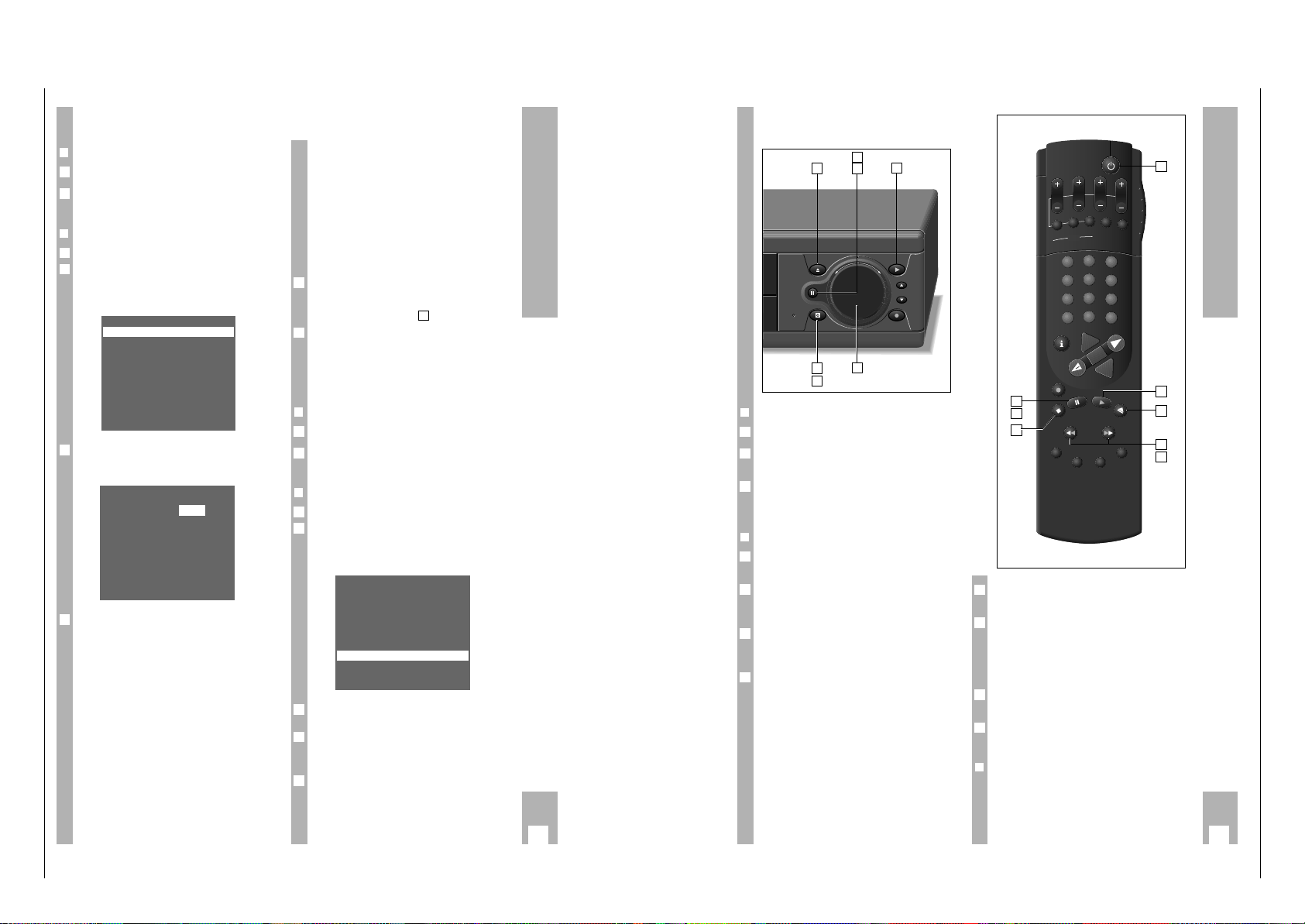
Bedienelemente
Hinweis:
Dieses Kapitel enthält Auszüge aus der Bedienungsanleitung.
Weitergehende Informationen entnehmen Sie bitte der
gerätespezifischen Bedienungsanleitung, deren Sachnummer Sie
in der entsprechenden Ersatzteilliste finden.
1 Ziffern-Tasten für verschiedene Eingaben
2 Unterbricht/aktiviert die Aufnahmebereitschaft des
Recorders
3 Zur Kontrolle und Ändern von Daten
4 Löscht Daten
5 Display
6 Cassettenfach
7 Standby Leuchtdiode
8 Pause bei Aufnahme
Standbild bei Wiedergabe
9 Cassettenauswurf
0 Schaltet den Recorder ab (standby)
! Bildsuchlauf vorwärts (bei Wiedergabe)
Vorlauf (bei Stop)
@ Startet die Wiedergabe
# Bildsuchlauf rückwärts (bei Wiedergabe)
Rücklauf (bei Stop)
$ Zur Programmplatzwahl (bei Stop)
% Aufnahme-Taste
^ Zur Programmplatzwahl (bei Stop)
& Jogscheibe
* Shuttlering
( Mikrofoneingang
) Audioeingang Links (Camcorder)
¡ Audioeingang Rechts (Camcorder)
™ Videoeingang (Camcorder)
£ Synchro Edit
≤ Netzanschluß
∞ EURO-AV-Buchsen (In / Out)
§ Synchro Edit
≥ Antennenbuchsen
• Dämpfungsschalter für Antennenbuchsen
ª Kanaleinsteller
1 2 3
4 5 6
7 8 9
SV0AV
1
7890 @$%&* ^56
ii
&
II
TIMER
ON / OFF
256 7890@$%^
SYNC.
MIC.
EDIT
VIDEO INL AUDIO IN R
TIMER
ON / OFF
e
%
ii
!#
&
TIMER
ON/OFF
8
%
$%^
1 2 3
4 5 6
7 8 9
SV0AV
1256
CHECK
CLEAR
34
256
TIMER
ON / OFF
EXT 1
EXT 1
EXT 2
EXT 2
79@$%^80&*
≤∞§
ii
II
t
ii
!#
890@
e
%
%
L
SIG
H
MOD.
FREQ.
x
ª•≥
()¡
£™
Allgemeiner Teil / General
1 - 8 GRUNDIG Service
5
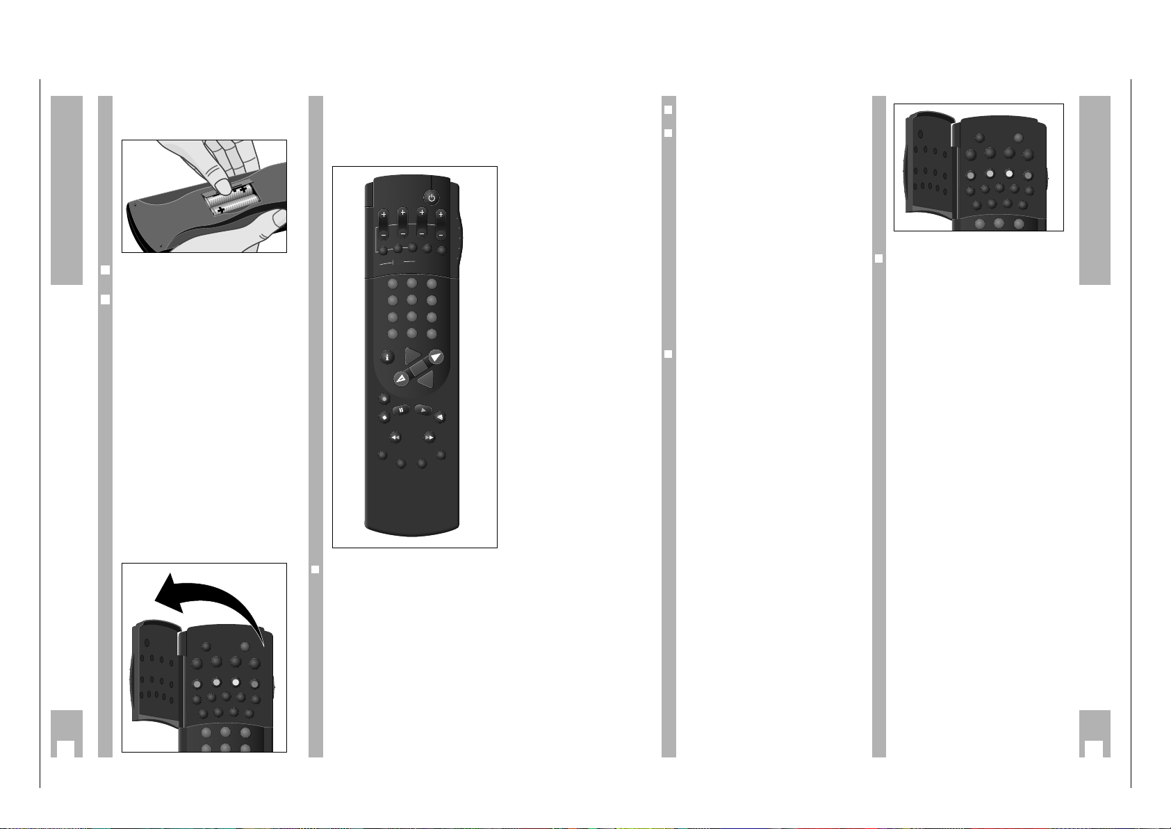
Die Fernbedienung
4
Die Fernbedienung
❒
Tasten unter der Klappe
¢
´
Ruft die Uhrzeit auf.
¢
8
Schaltet den Recorder ab (stand-by).
¢
#
Taste ohne Funktion.
¢
Taste ohne Funktion.
¢
<
Taste ohne Funktion.
¢
s
Taste ohne Funktion.
Z VPS (rot) Schaltet die VPS-Steuerung aus/ein.
Z ED/EW (grün) Wählt eine ”wöchentliche” oder ”täg-
liche” Aufzeichnung (bei der TIMERProgrammierung).
Z (gelb) Taste ohne Funktion.
Z C/S(blau) Schaltet von Kanalzahl auf Sonder-
kanalzahl (beim Programmeinstellen).
¢
Taste ohne Funktion.
¢
PAL/SEC Taste ohne Funktion.
¢
INS/DUB Taste ohne Funktion.
¢
TIP Taste ohne Funktion.
¢
CODE Zur Vorwahl verschiedener Sonder-
funktionen.
¢
COUNTER Schaltet zwischen Spielzeit- und
Bandlängenanzeige um.
¢
RESET Schaltet die Bandlängenanzeige auf
0.00.00.
¢
AUDIO Taste ohne Funktion.
¢
SAT Taste ohne Funktion.
3
2
1
´8
#
<
f
STOP
TIP
INS/DUB
PAL/SEC
CODE
RESET
AUDIO
COUNTER
SAT
ED/EW
VPS
C/S
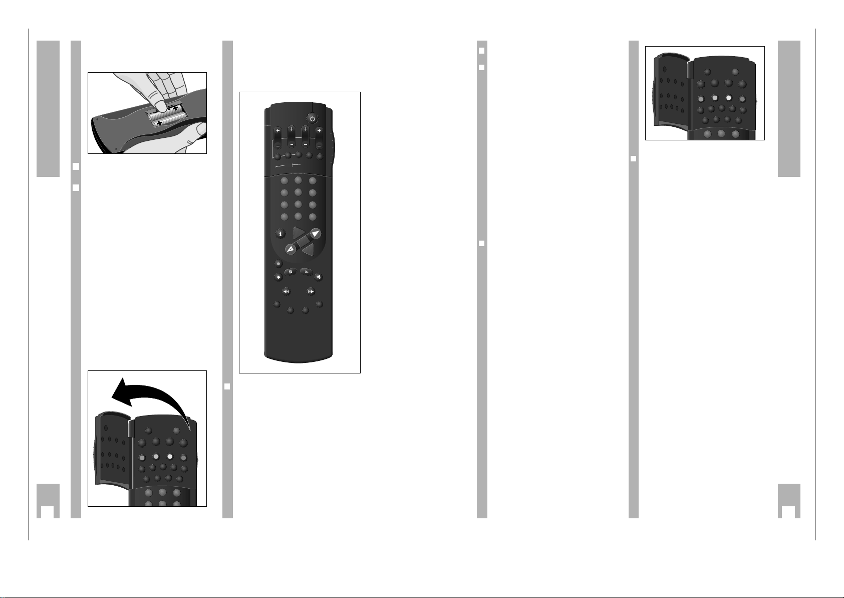
Batterien in die Fernbedienung
einlegen
Batteriefachdeckel abnehmen, dazu Schnapper
drücken und Deckel abnehmen.
Batterien (2x1,5 V, Typ Micro RO3P) einsetzen.
w
!
Polung der Batterien beachten; im Batteriefachboden markiert.
w
!
Wenn Ihr Recorder auf die Fernbedienbefehle nicht
mehr richtig reagiert, können die Batterien verbraucht sein.
Verbrauchte Batterien unbedingt entfernen.
Für Schäden, die durch ausgelaufene Batterien entstehen, kann nicht gehaftet werden.
Verbrauchte Batterien gehören in den Sondermüll
(Umweltschutz).
Die zwei Ebenen der
Fernbedienung
Die Tasten der Fernbedienung sind auf zwei Ebenen
angeordnet.
Auf der oberen Ebene finden Sie die Tasten, die Sie
für wesentliche Bedienfunktionen benötigen.
Auf der Ebene unter der Klappe finden Sie die
Tasten für Komfortfunktionen.
3
5
2
1
´8
#
<
f
STOP
TIP
INS/DUB
PAL/SEC
CODE
RESET
AUDIO
COUNTER
SAT
ED/EW
VPS
C/S
2
1
Auf einem Blick
Auf dieser und der nächsten Seite sind die Tasten
der Fernbedienung kurz erklärt.
Die Bedienung entnehmen Sie bitte dem jeweiligen
Kapitel dieser Bedienungsanleitung.
❒
Schalter zur Wahl der Videoebene
❒
Tasten für verschiedene Eingaben
¢
SP/LP Taste ohne Funktion.
¢
SV/V+ Eröffnet die ShowView Programmie-
rung.
1
...
0
Ziffern-Tasten für verschiedene Eingaben.
g
Taste ohne Funktion.
e
Wählt Programmplatz A1 oder A2
für die Aufnahme bzw. für die
TIMER-Programmierung.
h
Schaltet auf die Info-Tafel und
zurück auf das Fernsehbild.
C Cursor-Tasten,
FE zum Bewegen des Cursors
D (Schreibmarke);
zum Anwählen verschiedener
Funktionen;
zum Feinabstimmen der Programme.
G
Bestätigt Daten.
❒
Lauffunktions-Tasten
K Startet die Aufnahme.
H Beendet alle Funktionen (Stopp).
U Pause bei Aufnahme,
Standbild bei Wiedergabe.
Q Startet die Wiedergabe.
N Schiebt die Cassette aus.
Y Bildsuchlauf rückwärts bei Wieder-
gabe;
Band zurückspulen bei Stopp.
X Bildsuchlauf vorwärts bei Wieder-
gabe;
Band vorspulen bei Stopp.
¢
INDEX Wählt die INDEX-Such-Funktion.
¢
INDEX MARK Setzt Marken.
¢
INDEX ERASE Löscht Marken.
¢
TRACKING Aktiviert die Tracking-Funktion.
❒
Tasten für die TIMER-Programmierung
A Schaltet den Recorder ab (stand-by).
B PROG. Wählt das Programm.
B DAY Wählt den Tag.
B START Wählt die Startzeit.
B STOP Wählt die Stoppzeit.
¢
SET/CHECK Wählt die Tafel »Aufnahmeprogram-
mierung« an, zur Kontrolle und zum
Ändern von Daten.
¢
CLEAR Löscht Daten.
¢
ON/OFF Unterbricht/aktiviert die TIMER-Auf-
nahme.
➡
DAY START
ON/OFF
STOP
SP/LP
SV/V+
2
3
5
6
8
9
0
AVVPT
+
+
OK
PROG.
SET/CHECK
CLEAR
TIMER
1
4
7
-
I
N
D
E
X
IN
D
E
X
M
A
A
R
T
E
S
A
R
E
X
R
E
K
D
I
N
G
N
I
K
C

Allgemeiner Teil / General
GRUNDIG Service 1 - 9
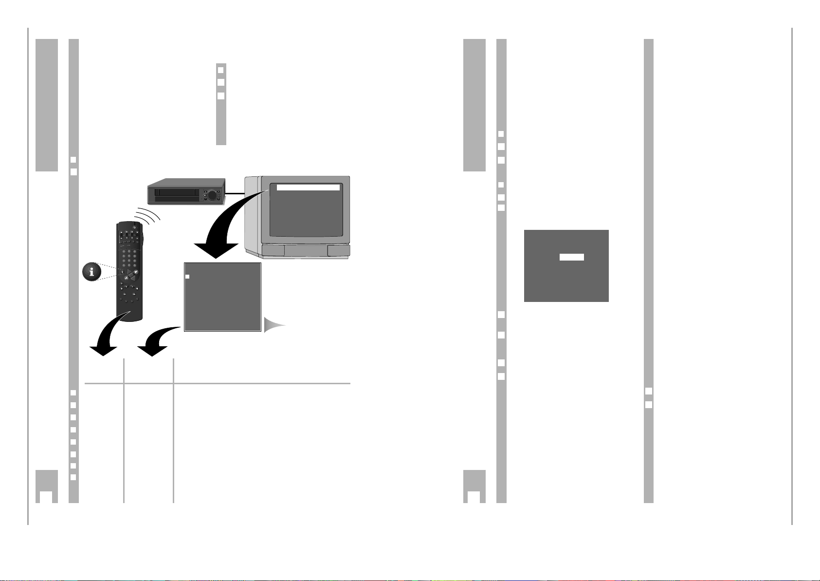
GRUNDIG Benutzerführung am Bildschirm des Fernsehgerätes
… bietet den Dialog zwischen Ihnen und dem
Recorder.
Viele Funktionen, die Sie mit der Fernbedienung
anwählen, beantwortet der Recorder mit Info-Tafeln
und Dialogzeilen am Bildschirm des Fernsehgerätes.
Tastensymbole der Fernbedienung und Dialogzeilen
zeigen die nächsten und möglichen Bedienschritte.
Sie werden Schritt für Schritt, einfach und verständlich geführt.
❒
Vorbereiten
Fernsehgerät einschalten.
Am Fernsehgerät den Programmplatz für den
Videorecorder wählen (AV-Programmplatz).
w
!
Ist der Recorder an ein Fernsehgerät mit Megalogic-Funktion angeschlossen, schaltet sich das Fernsehgerät nach Drücken der Taste h ein und schaltet automatisch auf den AV-Programmplatz.
2
1
6
Die Benutzerführung
Taste der Darstellung in der Funktion
Fernbedienung Info-Tafel und den
Dialogzeilen
❒
h i
Ruft die Info-Tafel auf und schaltet zurück zum Fernsehbild.
❒
1 2 … 90 0-9
Zur direkten Eingabe von Daten.
❒
DC op
Zum schrittweisen Anwählen von Funktionen oder von Zeilen in einer Tafel.
❒
FE iu
Zum Umblättern von Tafeln, zum Anwählen von Daten und zum Ändern von
Einstellungen.
❒
B
+
–
Zum schrittweisen Eingeben von Daten bei der TIMER-Aufnahme.
❒
G OK
Zum Aktivieren einer Funktion und zum Bestätigen von Daten und
Einstellungen.
❒ ¢
CLEAR CLEAR Zum Löschen von Daten.
❒ ¢
8
ohne Beendet jederzeit Info-Tafeln und Einstellungen
.
Aufn.-Programmierung
A2 Aufn.-Bereitsch.
Kindersicherung
Info Einblendungen
Installation
Uhrzeit/Datum stellen
––––––––––––––––
po OK i
PROG DAT START STOP
>
RTL2 01 12:01 13:00 *
ARD 02EW 10:01 11:00 *
PRO7 03ED 08:00 09:00
ZDF 04 00:00 00:10
VOX 05 00:20 00:30
SW3 06 01:40 02:12
–––––––––––––––––––––––
po CLEAR OK i
INFO-Tafel
❒
Info-Tafel aufrufen
Taste h der Fernbedienung drücken.
1
8
Einstellungen
Uhrzeit und Datum einstellen
w
!
Die Digitaluhr läuft auch weiter (bis zu 7 Tage),
wenn der Recorder vom Stromnetz getrennt ist. Die
Uhrzeit ist in der Anzeige nicht sichtbar und die
gelbe Anzeige am Recorder leuchtet nicht.
w
!
Stellen Sie – wenn notwendig – die Sprache der
Benutzerführung ein. Wie Sie das machen, steht im
Kapitel ”Sprache der Benutzerführung wählen”, auf
Seite 26.
❒
Vorbereiten
Fernsehgerät einschalten.
Am Fernsehgerät den AV-Programmplatz für den
Videorecorder wählen (dient als Kontrollmonitor).
❒
Bedienung
Info-Tafel mit Taste h aufrufen.
Mit den Tasten DC die Zeile »Uhrzeit/Datum stel-
len« anwählen und mit Taste G aufrufen.
– Die Tafel »Uhrzeit/Datum stellen« erscheint.
Uhrzeit mit den Ziffern-Tasten 1 … 0 vierstellig
eingeben.
Mit Taste D die Zeile »Datum« anwählen und
Datum mit den Ziffern-Tasten 1 … 0 sechsstellig
eingeben.
Eingabe mit Taste G speichern.
Einstellung mit Taste
¢
8
beenden.
6
5
4
3
Zeit: 20:15
Datum: 19.08.94
–––––––––––––––––––
po 0-9 OK i
2
1
2
1
Fernseh-Programme einstellen
Die Fernsehanstalten senden ihre Programme
durch Fernsehsender auf verschiedenen Frequenzen/Kanälen.
Der Recorder hat dafür ein eigenes Empfangsteil.
Damit kann er – unabhängig vom Fernsehgerät –
die Fernseh-Programme empfangen und aufzeichnen.
Vorher müssen Sie die Kanäle der FernsehProgramme am Recorder einstellen.
Es stehen 99 Programmplätze zur Verfügung, die
beliebig mit Fernseh-Programmen von der Antenne
oder dem Kabelanschluß belegt werden können.
Zum Einstellen gibt es mehrere Möglichkeiten:
1. Mit Übernahme der Daten vom Fernsehgerät.
Das Fernsehgerät muß mit Megalogic-Funktionen
ausgestattet sein.
2. Mit dem Suchlauf-Speicher-System (ATS euro
plus). Der Recorder sucht, sortiert und speichert
alle Kanalzahlen/Sonderkanalzahlen, die er an
seinem Standort empfangen kann.
Dieser Vorgang ist abhängig von der von Ihnen
gewählten Sprache, dem gewählten Land und der
Empfangsqualität der Fernseh-Programme.
Sollte Ihnen die vorgegebene Reihenfolge der
Fernseh-Programme nicht zusagen, können Sie
dies nachträglich ändern.
3. Durch direkte Eingabe der Daten.
4. Mit dem manuellen Suchlauf, wenn neue Fernseh-Programme hinzukommen, oder wenn der
Recorder ein Fernseh-Programm mit dem Suchlauf-Speicher-System nicht finden konnte.
Übernahme der Daten vom Fernsehgerät (Megalogic-Funktion)
Wird der Recorder an ein Fernsehgerät mit Megalogic-Funktion angeschlossen, übernimmt der Recorder automatisch die im Fernsehgerät gespeicherten
Fernseh-Programme.
Voraussetzung dafür ist, daß die folgende Bedienreihenfolge eingehalten wird.
w
!
Recorder und Fernsehgerät müssen mit dem beigepackten Megalogic-EURO-AV-Kabel verbunden
sein, und das Fernsehgerät muß eingeschaltet sein.
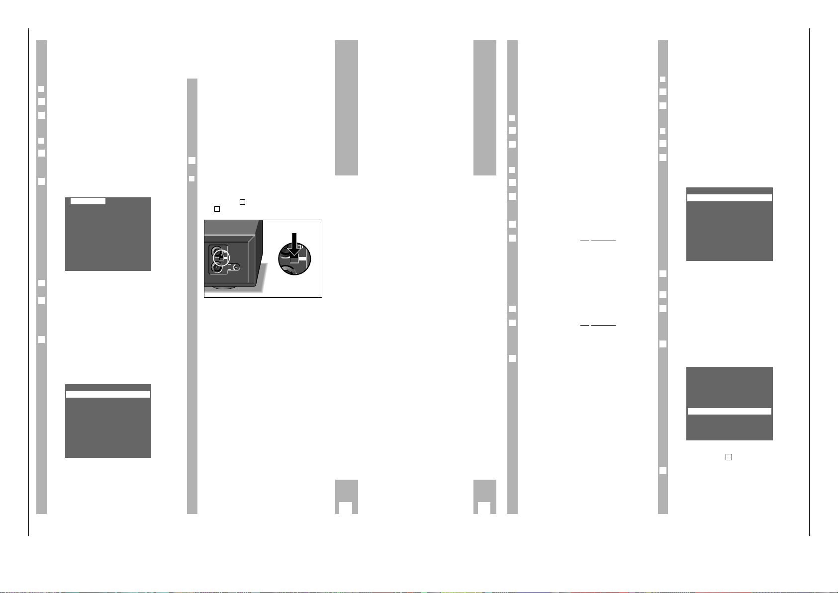
Netzstecker des Recorders ziehen.
Netzstecker des Recorders wieder einstecken.
– Der Recorder übernimmt automatisch die
Fernseh-Programme vom Fernsehgerät.
Dadurch erhält er die gleiche Programmbelegung
wie das Fernsehgerät.
2
1
➡
DAY START
PROG.
ON/OFF
SP/LP
CLEAR
SET/CHECK
TIMER
2
3
1
5
6
4
8
9
7
0
AVVPT
+
+
OK
-
I
N
D
E
X
IN
D
E
E
S
X
A
R
M
E
A
X
R
E
K
D
I
N
STOP
SV/V+
G
N
I
K
C
A
R
T
Dialogzeilen
Allgemeiner Teil / General
1 - 10 GRUNDIG Service
9
Einstellungen
Fernseh-Programme einstellen,
mit dem Suchlauf-Speicher-System
(ATS euro plus)
❒
Vorbereiten
Fernsehgerät einschalten.
Am Fernsehgerät den Programmplatz für den
Videorecorder wählen (AV-Programmplatz).
❒
Beispiel
Info-Tafel mit Taste h aufrufen.
– Die Info-Tafel erscheint, die Zeile »ATS euro plus«
ist markiert.
ATS euro plus-Funktion mit Taste G aktivieren.
– Die Tafel »ATS-Sprachwahl« erscheint.
Sprache des Aufstellungsortes mit den Tasten
F E DC wählen und mit Taste G bestätigen.
Land (Aufstellungsort) mit den Tasten FE DC
wählen.
w
!
Ist in der Tafel das von Ihnen benötigte Land nicht
vorhanden, wählen Sie die Zeile »??«.
ATS euro plus-Suchlauf mit Taste G starten.
– Anzeige am Recorder: »
ATS
« und »A«.
– Der Recorder sucht alle Kanalzahlen nach Fern-
seh-Programmen ab, sortiert und speichert sie.
– Nach Abschluß des Suchlaufs erscheint die Tafel
»Sender-Tabelle«.
w
!
Bei Sendeanstalten, die ein VPS-Signal senden,
wird die Sender-Kurzbezeichnung automatisch in
die »Sender-Tabelle« übernommen.
Pr CH PC DEC
01 C06 ARD AUS
02 C34 ZDF AUS
03 C59 BR3 AUS
04 C40 RTL AUS
05 C36 SAT1 AUS
06 C21 PRO7 AUS
07 C48 WDR AUS
–––––––––––––––––––
GRÜN: kopieren/sortieren
po
i u
CLEAR OK i
5
4
3
Deutsch Portuguesa
Espanol Svenska
Francais Norsk
EnglishDansk
Italiano Suomi
Nederlands
–––––––––––––––––––
po
i u
OK i
2
1
2
1
w
!
Für Sendeanstalten, die kein VPS-Signal senden,
kann die Sender-Kurzbezeichnung von Hand eingegeben werden.
Im Beispiel auf Seite 11 lesen Sie, wie Sie diese
Daten eingeben.
w
!
Wie Sie die Reihenfolge der Fernseh-Programme
ändern, Daten von Hand eingeben oder Daten
löschen, lesen Sie in den Beispielen auf den nächsten Seiten.
Einstellung mit Taste
¢
8
beenden.
❒
Bildstörungen beseitigen
Sollte der Recorder den ATS euro plus-Suchlauf
nicht ordnungsgemäß ausführen, Dämpfungsschalter in Stellung schieben und die Einstellung ab
Pkt. des Beispiels wiederholen.
x
L
H
SIG
MOD.
FREQ.
L
H
SIG
L
H
SIG
1
H
6
➡
10
Einstellungen
Fernseh-Programme umsortieren –
von Hand
❒
Vorbereiten
Fernsehgerät einschalten.
Am Fernsehgerät den Programmplatz für den
Videorecorder wählen (AV-Programmplatz).
❒
Beispiel
Info-Tafel mit Taste h aufrufen.
Mit den Tasten DC die Zeile »Sendertabelle«
anwählen und mit Taste G aufrufen.
– Die »Sender-Tabelle« erscheint, der gewählte
Programmplatz ist markiert.
Programmplatz mit den Tasten DC E F
anwählen.
Programmplatz mit Taste Z ED/EW (grün) markieren.
Neuen Programmplatz mit den Tasten DC
anwählen.
– Die Daten des markierten Programmplatzes wer-
den an den neuen Programmplatz verschoben.
Einstellungen mit Taste G speichern.
– Die folgenden Fernseh-Programme verschieben
sich um eine Position.
Zum Umsortieren von weiteren Fernseh-Programmen Vorgang ab Pkt. wiederholen.
Einstellung mit Taste
¢
8
beenden.
7
3
Pr CH PC DEC
01 C06 ARD AUS
02 C34 ZDF AUS
03 C59 BR3 AUS
04 C21 PRO7 AUS
05 C36 SAT1 AUS
06 C40 RTL AUS
07 C48 WDR AUS
–––––––––––––––––––
GRÜN: kopieren/sortieren
po
i u
CLEAR OK i
6
5
4
3
Pr CH PC DEC
01 C06 ARD AUS
02 C34 ZDF AUS
03 C59 BR3 AUS
04 C40 RTL AUS
05 C36 SAT1 AUS
06 C21 PRO7 AUS
07 C48 WDR AUS
–––––––––––––––––––
GRÜN: kopieren/sortieren
po
i u
CLEAR OK i
2
1
2
1
Fernseh-Programme umsortieren –
mit der Follow TV-Funktion
Hierbei erhält der Recorder die gleiche Programmplatzbelegung wie das Fernsehgerät.
w
!
Recorder und Fernsehgerät müssen mit einem
EURO-AV-Kabel verbunden sein.
❒
Vorbereiten
Fernsehgerät einschalten.
Am Fernsehgerät den Programmplatz für den
Videorecorder wählen (AV-Programmplatz).
❒
Beispiel
Info-Tafel mit Taste h aufrufen.
Mit den Tasten DC die Zeile »Follow TV starten«
anwählen und mit Taste G aktivieren.
– Anzeige am Recorder: »
SELECT TV POI
«.
Am Fernsehgerät den Programmplatz 1 wählen.
An der Fernbedienung des Recorders Taste G
drücken.
– Anzeige am Recorder: »
PLEASE WAIT
«.
– Der Recorder ”sucht” nach den Daten des ersten
Programmplatzes des Fernsehgerätes. Er belegt
seinen ersten Programmplatz mit dem gleichen
Fernseh-Programm wie am Fernsehgerät.
– Ist dieser Vorgang beendet, erscheint in der
Anzeige des Recorders: »
SELECT TV PO2
«.
Am Fernsehgerät Programmplatz 2 wählen.
An der Fernbedienung des Recorders Taste G
drücken.
– Einstellung so oft wiederholen, bis alle Fernseh-
Programme sortiert sind.
Einstellung mit Taste
¢
8
beenden.
w
!
Wenn bei dieser Einstellung zwei Fernsehanstalten
das gleiche Programm senden, kann es zu Fehlern
in der Zuordnung führen.
Einstellung wiederholen, wenn die Fernsehanstalten
unterschiedliche Programme senden, oder Fernseh-Programme von Hand umsortieren.
7
6
5
4
3
2
1
2
1
➡
Allgemeiner Teil / General
GRUNDIG Service 1 - 11
11
Einstellungen
Daten von Hand eingeben
❒
Vorbereiten
Fernsehgerät einschalten.
Am Fernsehgerät den Programmplatz für den
Videorecorder wählen (AV-Programmplatz).
❒
Beispiel
Info-Tafel mit Taste h aufrufen.
Mit den Tasten DC die Zeile »Sendertabelle«
anwählen und mit Taste G aufrufen.
– Die »Sender-Tabelle« erscheint, der gewählte
Programmplatz ist markiert.
Programmplatz mit den Tasten DC E F
anwählen, danach Taste G drücken.
– Die Tafel »Programm« erscheint.
Datenzeile mit den Tasten DC anwählen.
Die Texte bedeuten:
KANAL: die Kanalzahl oder die Frequenz des
Fernseh-Programms,
NAME: die Sender-Kurzbezeichnung
(max. 5 Stellen),
DECODER: Programmplatz für externen
Decoder aktivieren,
FEINABST.: Bild feinabstimmen.
w
!
Die weitere Bedienung entnehmen Sie bitte den Dialogzeilen der »Programm«-Tafel.
4
PROGRAMM 08
KANAL: C05
NAME: ––––
DECODER: EIN AUS
FEINABST.: -3
–––––––––––––––––––
ROT: Frq/Kan BLAU: C/S
po
iu
OK i
3
Pr CH PC DEC
01 C06 ARD AUS
02 C34 ZDF AUS
03 C59 BR3 AUS
04 C40 RTL AUS
05 C36 SAT1 AUS
06 C21 PRO7 AUS
07 C48 WDR AUS
–––––––––––––––––––
GRÜN: kopieren/sortieren
po
i u
CLEAR OK i
2
1
2
1
w
!
Alternativ zur Eingabe der Kanalzahl kann die Frequenz des Fernseh-Programms eingegeben werden, dazu Taste Z VPS (rot) drücken.
– Die Anzeige wechselt von »KANAL« auf
»FREQUENZ«.
Benötigte Frequenz mit den Ziffern-Tasten
1…0 vierstellig eingeben.
w
!
Sind Kanalzahl oder Frequenz nicht bekannt, kann
ein Suchlauf gestartet werden, dazu Taste E
drücken.
Eingabe mit Taste G speichern.
– Es erscheint wieder die »Sender-Tabelle«.
Zur Dateneingabe für die nächsten Programmplätze Einstellung ab Pkt. wiederholen.
Einstellung mit Taste
¢
8
beenden.
Daten eines Programmplatzes
löschen
❒
Vorbereiten
Fernsehgerät einschalten.
Am Fernsehgerät den Programmplatz für den
Videorecorder wählen (AV-Programmplatz).
❒
Beispiel
Info-Tafel mit Taste h aufrufen.
Mit den Tasten DC die Zeile »Sendertabelle«
anwählen und mit Taste G aufrufen.
– Die »Sender-Tabelle« erscheint, der gewählte
Programmplatz ist markiert.
Programmplatz mit den Tasten DC E F
anwählen.
Datenzeile mit Taste
¢
CLEAR löschen.
– Die folgenden Fernseh-Programme rücken um
einen Programmplatz vor.
Einstellung mit Taste
¢
8
beenden.
5
4
3
Pr CH PC DEC
01 C06 ARD AUS
02 C34 ZDF AUS
03 C59 BR3 AUS
04 C40 RTL AUS
05 C36 SAT1 AUS
06 C21 PRO7 AUS
07
–––––––––––––––––––
GRÜN: kopieren/sortieren
po
i u
CLEAR OK i
2
1
2
1
6
3
5
13
Wiedergabe
❒
Vorbereiten
Fernsehgerät einschalten.
Am Fernsehgerät den Programmplatz für den
Videorecorder wählen (AV-Programmplatz).
Bespielte Cassette in das Cassettenfach schieben.
Der Videorecorder stellt automatisch die Spielzeit
der Cassette fest.
❒
Bedienung
Wiedergabe mit Taste Q der Fernbedienung oder
Taste S am Recorder starten.
Pause/Standbild* anwählen, dazu während der
Wiedergabe Taste U der Fernbedienung oder
Taste U am Recorder drücken.
Standbilder schrittweise weiterschalten, dazu
während der Wiedergabe-Pause Taste U der Fernbedienung oder Taste U am Recorder drücken.
Verschiedene Wiedergabegeschwindigkeiten anwählen, – vorwärts/rückwärts, dazu während der
Wiedergabe die Tasten XY der Fernbedienung
drücken, oder
Shuttle-Ring am Recorder nach rechts oder links
drehen.
w
!
Aus den Wiedergabe-Funktionen Pause/Standbild
und den verschiedenen Wiedergabefunktionen
zurück zur normalen Wiedergabe, dazu Taste Qder
Fernbedienung oder Taste S am Recorder
drücken.
4
3
2
1
3
2
1
Wiedergabe mit Taste H der Fernbedienung oder
Taste i am Recorder beenden.
Band vor-/zurückspulen, dazu in Funktion Stopp die
Tasten XYder Fernbedienung drücken, oder
Shuttle-Ring am Recorder nach rechts oder links
drehen.
Umspulen mit Taste H der Fernbedienung oder
Taste i am Recorder beenden.
Cassette entnehmen, dazu Taste N der Fernbedienung oder Taste P am Recorder drücken.
Recorder mit Taste A der Fernbedienung oder
Taste i am Recorder abschalten.
❒
Megalogic-Funktion
Ist der Recorder an ein Fernsehgerät mit Megalogic-Funktionen angeschlossen, schaltet sich das
Fernsehgerät nach dem Starten der Wiedergabe ein
und schaltet automatisch auf den AV-Programmplatz.
8
7
6
5
➡
Auf einem Blick
7
5
8
4
3
2
1
8
1
7
2
3
5
4
6
* Standbild mit Störstreifen.
DAY START
ON/OFF
STOP
SP/LP
SV/V+
2
3
5
6
8
9
0
AVVPT
+
+
OK
PROG.
SET/CHECK
CLEAR
TIMER
1
4
7
-
I
N
D
E
X
IN
D
E
X
M
A
R
K
I
K
C
A
R
T
E
S
A
R
E
X
E
D
I
N
G
N

Allgemeiner Teil / General
1 - 12 GRUNDIG Service
14
Wiedergabe
Bild-/Tonkorrekturen
❒
Bild-/Tonkorrektur – automatisch
Nach dem Einschieben der Cassette und dem Starten der Wiedergabe stimmt der Recorder automatisch auf beste Bildqualität ab (Auto Tracking).
– Während der Abstimmung erscheint am Recorder
die Anzeige »
AUTO-TRACK
« und die Bild-/Ton-
qualität kann sich verändern.
❒
Bild-/Tonkorrektur – manuell
Taste
¢
TRACKING drücken.
– Anzeige am Recorder: »
TRACKING
«.
– Anzeige am Bildschirm: »SPURLAGE«.
Tracking (Spurlage)-Einstellung mit den Tasten
F
E
der Fernbedienung durchführen.
Einstellung mit Taste Gspeichern.
❒
Bild-/Tonverbesserung für
fremdbespielte Cassetten
Wenn bei der Wiedergabe von fremdbespielten
Cassetten das Bild springt oder durchläuft, drücken
Sie nacheinander die Taste
¢
CODE, die Ziffern-
Tasten
8511
und Taste G.
– Kurzzeitige Anzeige am Recorder: »ON«.
❒
Bildverbesserung des Standbildes
Wenn bei der Wiedergabefunktion Standbild das
Bild zittert oder unruhig wirkt, kann es optimiert
werden.
Während Standbild die Taste h drücken.
Mit Taste D die Zeile »Pausebild optimieren«
anwählen und mit Taste G aufrufen.
– Anzeige am Recorder: »
JITTER
«.
– Anzeige am Bildschirm: »PAUSEBILD
OPTIMIEREN«.
Mit den Tasten
D oder C
das Bild nach subjektiv
bestem Eindruck einstellen und dann Taste
G
drücken.
❒
Bildschärfe optimieren
(Automatic Contour Control Plus)
Nach dem Einschieben der Cassette und dem Starten der Wiedergabe stimmt der Recorder automatisch auf optimale Bildschärfe ab.
3
2
1
3
2
1
Bestimmte Aufzeichnungen finden
V
ideo Index Such System (VISS)
Dieses System ermöglicht präzises und schnelles
Auffinden des Beginns jeder Eigenaufnahme.
❒
Bandstelle markieren – automatisch
Die ”Marken” werden automatisch – bei Beginn
jeder Eigenaufnahme – auf das Band gesetzt.
❒
Bandstelle markieren – von Hand
Zusätzlich zu den automatischen ”Marken” können
per Tastendruck ”Marken” auf das Band gesetzt
werden.
Während der Aufnahme oder der Wiedergabe an
der Bandstelle, die ”markiert” werden soll
Taste
¢
INDEX MARK drücken.
– Anzeige am Recorder: »
INDEX MARK
«.
– Anzeige am Bildschirm: »INDEX SETZEN«.
❒
Bandstelle finden
Ausgangspunkt ist die aktuelle Bandposition.
Die Suche kann zu den 9 vorherigen oder den
9 folgenden Marken erfolgen.
Taste
¢
INDEX drücken.
– Anzeige am Recorder: »
INDEX
« und eine Nummer.
– Anzeige am Bildschirm: »INDEX« und eine Num-
mer.
Mit den Ziffern-Tasten 1…9 eine Ziffer – für die
Marke 1 bis 9 – eingeben und danach Taste Y oder
X drücken, oder
Shuttle-Ring nach links oder rechts drehen.
– Das Band wird zu der gewählten Marke gespult,
dort beginnt die Wiedergabe.
❒
Marke vom Band löschen
Taste
¢
INDEX drücken.
Mit den Ziffern-Tasten 1…9 eine Ziffer – für die
Marke 1 bis 9 – eingeben und danach Taste Y oder
X drücken, oder
Shuttle-Ring nach links oder rechts drehen.
– Das Band wird zu der gewählten Marke gespult,
dort beginnt die Wiedergabe.
– Blinkende Anzeige am Recorder: »
INDEX
«.
Während die »
INDEX
«-Anzeige blinkt, kann die
Marke mit Taste
¢
INDEX ERASE gelöscht werden.
– Anzeige am Recorder: »
INDEX ERASE
«.
– Anzeige am Bildschirm: »INDEX LÖSCHEN«.
3
2
1
2
1
15
❒
Vorbereiten
Fernsehgerät einschalten.
Am Fernsehgerät den Programmplatz für den
Videorecorder wählen (AV-Programmplatz).
Cassette mit ausreichender Spieldauer in das Cas-
settenfach schieben.
❒
Bedienung
Programmplatz wählen, schrittweise mit den Tasten
DC der Fernbedienung oder den Tasten ab
am Recorder;
direkt mit den Ziffern-Tasten 1 ... 0 der Fernbedienung.
w
!
Für zweistellige Programmplätze die Ziffern-Tasten
kurz hintereinander drücken.
Aufnahme starten, dazu Taste K der Fernbedienung oder Taste M am Recorder länger drücken.
Aufnahmepause mit Taste U der Fernbedienung
oder Taste U am Recorder anwählen.
Aufnahme mit Taste K der Fernbedienung oder
Taste M am Recorder fortsetzen.
Aufnahme mit Taste H der Fernbedienung oder
Taste i am Recorder beenden.
Band vor-/zurückspulen, dazu in Funktion Stopp
Taste Y oder X der Fernbedienung drücken, oder
Shuttle-Ring nach rechts oder links drehen.
Umspulen mit Taste H der Fernbedienung oder
Taste i am Recorder beenden.
5
4
3
2
1
3
2
1
Cassette entnehmen, dazu Taste N der Fernbedienung oder Taste P am Recorder drücken.
Recorder mit Taste A der Fernbedienung oder
Taste i am Recorder abschalten.
❒
Megalogic-Funktion
Ist der Recorder an ein Fernsehgerät mit Megalogic-Funktionen angeschlossen, kann mit Taste K
der Fernbedienung oder Taste M am Recorder
das Fernseh-Programm, das am Bildschirm des
Fernsehgerätes zu sehen ist, aufgezeichnet werden.
Der Programmplatz muß am Recorder nicht
gewählt werden.
7
6
Aufnahme
Auf einem Blick
6
5
2
1
43
7
1
1
6
5
3
2
4
7
DAY START
PROG.
ON/OFF
SP/LP
CLEAR
SET/CHECK
TIMER
2
3
1
5
6
4
8
9
7
0
AVVPT
+
+
OK
-
I
N
D
E
X
IN
D
E
E
S
X
A
R
M
E
A
X
R
E
K
D
I
N
STOP
SV/V+
G
N
I
K
C
A
R
T

Allgemeiner Teil / General
GRUNDIG Service 1 - 13
24
Sonderfunktionen
Die Kindersicherung
Mit der Kindersicherung lassen sich alle Funktionen
verriegeln.
Selbst eine Cassette, die nachträglich eingeschoben
wird, muß im Recorder bleiben, bis Sie ihn wieder
entriegeln.
❒
Kindersicherung aktivieren
Info-Tafel mit Taste h aufrufen.
Mit den Tasten DC die Zeile »Kindersicherung «
anwählen und mit Taste G aufrufen.
– Die Tafel »Kindersicherung« erscheint.
Geheimnummer mit den Ziffern-Tasten 1 … 0
vierstellig eingeben und mit Taste G bestätigen.
– Der Recorder schaltet die Tafel ab.
– Anzeige am Recorder: »
LOCKED
« und die Uhrzeit.
w
!
Der Recorder ist verriegelt.
w
!
Falls Sie die Geheimnummer vergessen oder verlegen, kann der Fachhändler weiterhelfen.
❒
Kindersicherung abschalten
Beliebige Taste drücken.
– Die Tafel »Kindersicherung« erscheint, anstatt
der Geheimnummer zeigt die Tafel »
****
«.
Vierstellige Geheimnummer mit den Ziffern-Tasten
1 … 0 eingeben und mit Taste G bestätigen.
– Der Recorder schaltet die Tafel ab, die Sperre ist
aufgehoben.
2
1
3
GEHEIMNUMMER: ––––
–––––––––––––––––––
0-9 OK i
2
1
Funktionsanzeige (OSD – ON SCREEN
D
ISPLAY) einstellen
Die Dauer der Funktionsanzeige am Bildschirm des
Fernsehgerätes kann eingestellt werden.
❒
Beispiel
Info-Tafel mit Taste h aufrufen.
Mit den Tasten DC die Zeile »Info Einblendun-
gen« anwählen und mit Taste G aufrufen.
– Die Tafel »Info Einblendungen« erscheint.
Gewünschte Einstellung mit den Tasten DC
anwählen und mit Taste G bestätigen.
Einstellung mit Taste
¢
8
beenden.
4
3
OSD AUS
OSD 5 SEKUNDEN
OSD PERMANENT
–––––––––––––––––––
po OK i
2
1
25
Sonderfunktionen
❒
Fernbedienen der beiden Recorder
Schalter in Stellung VIDEO 2, Sie bedienen Ihren
GV 500;
Schalter in Stellung VIDEO 1; Sie bedienen den
zweiten Recorder.
w
!
Steht der Schalter 1 VIDEO 2 bei der Bedienung des
GV 500 nicht in der gewählten Videoebene, signalisiert die Anzeige »
VID I
« bzw. »
VID 2
« am Recorder, daß die Fernbedienung auf die andere Videoebene umgeschaltet werden muß.
1
2
TV
1
2
TV
SP/LP
ON/OFF
CLEAR
SV/V+
STOP
TART
9
3
6
2
2
1
Fernbedienen anderer GRUNDIGVideorecorder
Mit dieser Fernbedienung können verschiedene
GRUNDIG-Videorecorder unabhängig voneinander
bedient werden.
Ihren GV 500 und einen zweiten Videorecorder der
Serie VS 600 bis VS 900 und ab der Serie GV 200.
Damit die Recorder die Fernbedienungsbefehle
richtig auswerten können, muß der GV 500 umgestellt werden.
❒
Vorbereiten
Fernsehgerät einschalten.
Am Fernsehgerät den Programmplatz für den
Videorecorder wählen (AV-Programmplatz).
❒
Videoebene für den GV 500 einstellen
Info-Tafel mit Taste h aufrufen.
Mit den Tasten DC die Zeile »Installation«
anwählen und mit Taste G aufrufen.
Mit den Tasten DC die Zeile »Videoebene«
anwählen und mit Taste G aufrufen.
– Die Tafel »Videoebene« erscheint.
Videoebene 2 mit den Tasten FEwählen.
Einstellung mit Taste G bestätigen.
– Der Recorder schaltet die Tafel ab.
5
4
Videoebene:
1 2
–––––––––––––––––––
iu OK i
3
2
1
2
1
VIDEO 1
VIDEO 2
TV
Allgemeiner Teil / General
1 - 14 GRUNDIG Service
Operating Elements
Note:
This chapter contains excerpts from the operating instructions. For
further particulars please refer to the appropriate user instructions
part number of which is indicated in the relevant spare parts list.
1 Numbered buttons for various entries
2 Interrupts/activates the record stand-by mode of the
recorder
3 For checking and changing of data
4 Clears data
5 Display
6 Cassette compartment
7 Stand-by light emitting diode
8 Pause on Record
freeze-frame on playback
9 Cassette eject
0 Switches the recorder to stand-by
! Forward picture search (on playback)
fast forward (on stop)
@ Starts playback
# Reverse picture search during playback
rewind (on stop)
$ For selecting programme positions (on stop)
% Record button
^ For selecting programme positions (on stop)
& Jog rotary disk
* Shuttle ring
( Microphone input
) Audio input left (camcorder)
¡ Audio input right (camcorder)
™ Video input (camcorder)
£ Synchro Edit
≤ Mains connection
∞ EURO AV sockets (in / out)
§ Synchro Edit
≥ Aerial sockets
• Attenuation switch for aerial level
ª Channel selection
1 2 3
4 5 6
7 8 9
SV0AV
1
7890 @$%&* ^56
ii
&
II
TIMER
ON / OFF
256 7890@$%^
SYNC.
MIC.
EDIT
VIDEO INL AUDIO IN R
TIMER
ON / OFF
e
%
ii
!#
&
TIMER
ON/OFF
8
%
$%^
1 2 3
4 5 6
7 8 9
SV0AV
1256
CHECK
CLEAR
34
256
TIMER
ON / OFF
EXT 1
EXT 1
EXT 2
EXT 2
79@$%^80&*
≤∞§
ii
II
t
ii
!#
890@
e
%
%
L
SIG
H
MOD.
FREQ.
x
ª•≥
()¡
£™
Allgemeiner Teil / General
GRUNDIG Service 1 - 15
4
The Remote Control
Inserting batteries into the remote
control
Press the catch and remove the cover from the battery compartment.
Insert the batteries (2x 1.5V, type Micro RO3P).
w
!
Observe correct polarity; marked on the bottom of
the battery compartment.
w
!
If your recorder no longer responds correctly to the
remote control commands, the batteries may be
exhausted.
Exhausted batteries must be removed.
The manufacturer cannot be held responsible for
damage resulting from battery leakage.
Exhausted batteries must be handed over to a special waste collecting point (environmental protection).
The two levels of the remote
control
The buttons on the remote control are located on
two separate levels.
The buttons that are required for essential operating functions are located on the upper level.
The buttons that are required for convenience functions are located on the level under the cover flap.
3
5
2
1
´8
#
<
f
STOP
TIP
INS/DUB
PAL/SEC
CODE
RESET
AUDIO
COUNTER
SAT
ED/EW
VPS
C/S
2
➡
At a glance
The buttons on the remote control are explained
briefly on this page and the following page.
For operation please see the respective chapter of
these operating instructions.
❒
Buttons for TIMER programming
A Switches the recorder off (stand-by).
B PROG. Selects the TV station.
B DAY Selects the day.
B START Selects the start time.
B STOP Selects the stop time.
¢
SET/CHECK Calls up the »Record Programming«
table for checking, and for altering
data.
¢
CLEAR Deletes data.
¢
ON/OFF Interrupts/activates TIMER recor-
ding.
5
The Remote Control
❒
Buttons under the cover flap
¢
´
Calls up the time.
¢
8
Switches the recorder off (stand-by).
¢
#
No function.
¢
No function.
¢
<
No function.
¢
s
No function.
Z VPS (red) Switches VPS control off/on.
Z ED/EW (green) Selects a “weekly” or “daily” recor-
ding (when programming with the
TIMER).
Z (yellow) No function.
Z C/S(blue) Switches from channel number to
special channel number (when
tuning TV stations).
¢
No function.
¢
PAL/SEC No function.
¢
INS/DUB No function.
¢
TIP No function.
¢
CODE For preselection of various special
functions.
¢
COUNTER Switches between the playing time
and tape length display.
¢
RESET Resets the tape length display to
0.00.00.
¢
AUDIO No function.
¢
SAT No function.
3
2
1
´8
#
<
f
STOP
TIP
INS/DUB
PAL/SEC
CODE
RESET
AUDIO
COUNTER
SAT
ED/EW
VPS
C/S
❒
Switch for selecting the VCR address
❒
Buttons for various entries
¢
SP/LP No function.
¢
SV/V+ Initiates ShowView programming.
1
...
0
Numbered buttons for various
entries.
g
No function.
e
Selects programme position A1 or
A2 for recording or TIMER programming.
h
Switches to the info table and back
to the TV picture.
C Cursor buttons,
FE for moving the cursor
D (marker);
for selecting various functions;
for finetuning the TV stations.
G
Confirms data.
❒
Drive mechanism buttons
K Starts recording.
H Stops all functions.
U Pause in recording mode,
freeze-frame in playback mode.
Q Starts playback.
N Ejects the cassette.
Y Picture search reverse in playback
mode;
rewind tape in stop mode.
X Picture search forwards in playback
mode;
tape fast forward in stop mode.
¢
INDEX Selects the INDEX search function.
¢
INDEX MARK Sets markers.
¢
INDEX ERASE Erases markers.
¢
TRACKING Activates the tracking function.
DAY START
ON/OFF
STOP
SP/LP
SV/V+
2
3
5
6
8
9
0
AVVPT
+
+
OK
PROG.
SET/CHECK
CLEAR
TIMER
1
4
7
-
I
N
D
E
X
IN
D
E
X
M
A
R
C
A
R
T
E
S
A
R
E
X
E
K
D
I
N
G
N
I
K
Allgemeiner Teil / General
1 - 16 GRUNDIG Service
The GRUNDIG user guide on the
screen of the TV set
… offers a dialogue between you and the recorder.
The recorder responds to many functions which
you select using the remote control, with info tables
and dialogue lines on the screen of the TV set.
Button symbols for the remote control and dialogue
lines indicate the next operating step, and options.
You are guided step by step, simply and understandably.
❒
Preparation
Switch the TV set on.
Select the programme position for the video recor-
der at the TV set (AV programme position).
w
!
If the recorder is connected to a TV set with Megalogic functions, the procedure is carried out automatically. When you press the h button the TV set
is switched on and the AV programme position is
selected automatically.
2
1
6
The User Guide
Button on the Representation in Function
remote control the info table and
the dialogue lines
❒
h i
Calls up the info table and switches back to the TV picture.
❒
1 2 … 90 0–9
For entering data directly.
❒
DC op
For step by step selection of functions or lines in a table.
❒
FE iu
For switching between tables, for selecting data, and for altering settings.
❒
B
+
–
For entering data step by step for TIMER recording.
❒
G OK
For activating a function and for confirming data and settings.
❒ ¢
CLEAR CLEAR For deleting data.
❒ ¢
8
none To end info tables and settings at any time
.
Record Programming
A2 Record Prepared
Child lock
Info Duration
Installation
Set Time/Date
––––––––––––––––
po OK i
PROG DAT START STOP
>
RTL2 01 12:01 13:00 *
ARD 02EW 10:01 11:00 *
PRO7 03ED 08:00 09:00
ZDF 04 00:00 00:10
VOX 05 00:20 00:30
SW3 06 01:40 02:12
–––––––––––––––––––––––
po CLEAR OK i
INFO table
❒
Calling up the info table
Press the h button on the remote control.
1
Dialogue lines
8
Settings
Setting the time and date
w
!
The digital clock continues to operate (for up to 7
days) after the recorder has been disconnected
from the mains supply. However, the time is not
displayed and the yellow indicator on the recorder
is off.
w
!
If necessary, set the language for the user guide.
Follow the instructions in the chapter “Selecting the
language for the user guide” on page 26.
❒
Preparation
Switch the TV set on.
Select the AV programme position for the video
recorder at the TV set (serves as monitor).
❒
Operation
Call up the info table using the h button.
Use the DC buttons to select the »Set Time/Date«
line and call it up using the G button.
– The »Set Time/Date« table appears.
Enter the time as a four-digit number using the
numbered buttons 1 … 0.
Use the D button to select the » Date « line and
enter the date as a six-digit number using the numbered buttons 1 … 0.
Confirm the entry using the G button.
End the setting using the
¢
8
button.
6
5
4
3
Time: 20:15
Date: 19.08.94
–––––––––––––––––––
po 0-9 OK i
2
1
2
1
Tuning TV stations
Television stations broadcast programmes on different frequencies/channels.
The recorder has a built-in receiver. It can thus
receive and record television programmes independently of the TV set.
First, you must tune your recorder to the channels
used by the different TV stations.
99 programme positions are available. They can be
occupied as required with TV stations from the aerial or a cable connection.
A number of options are available for tuning:
1. By transfer of data from the TV set.
The TV set must be provided with Megalogic functions.
2. With the automatic tuning system (ATS euro
plus). The recorder searches, sorts, and stores
all channels/special channels which can be received at its location.
This procedure depends on the language and
country you select, as well as the quality of
reception of the TV stations.
If you are not satisfied with the order in which
the TV stations are allocated, the order can be
changed later.
3. By entering data directly.
4. By searching manually, for example if there are
new TV stations, or if the recorder cannot find a
TV station with the automatic tuning system.
Accepting data from the TV set
(Megalogic function)
If the recorder is connected to a TV set with Megalogic function, the recorder automatically accepts
the TV programmes that are stored in the TV set.
To enable the recorder to this, you must carry out
the following steps in the order indicated.
w
!
Recorder and TV set must be connected with the
EURO-AV cable provided with your recorder, and
the TV set must be switched on.
Remove the plug for the recorder from the mains.
Re-insert the plug for the recorder into the mains.
– The recorder automatically accepts the TV
programmes from the TV set.
Thus the recorder will have the same programme
position assignments as the TV set.
2
1
➡
PROG.
CLEAR
SET/CHECK
TIMER
1
4
7
I
N
D
E
X
IN
D
E
DAY START
STOP
ON/OFF
SP/LP
SV/V+
2
3
5
6
8
9
0
AVVPT
+
+
OK
-
G
N
I
K
C
A
R
T
E
S
X
A
R
M
E
A
X
R
E
K
D
I
N
Dialogzeilen
Allgemeiner Teil / General
GRUNDIG Service 1 - 17
9
Settings
Tuning to TV stations with the
automatic tuning system
(ATS euro plus)
❒
Preparation
Switch the TV set on.
Select the programme position for the video recor-
der at the TV set (AV programme position).
❒
Example
Call up the info table using the h button.
– The info table appears, the » ATS euro plus «
line is marked.
Activate the ATS euro plus function using the G
button.
– The »ATS Select language« table appears.
Select the language of your location using the
FE DC buttons and confirm using the G
button.
Select the country (location) using the F E DC
buttons.
w
!
If the country you require is not to be found in the
table, select the »??« line.
Start the ATS euro plus search using the G but-
ton.
– Display at recorder: »
ATS
« and »A«.
– The recorder searches all channels for TV stati-
ons, and sorts and stores them.
– When the search has been completed the » TV
Station Table« appears.
w
!
The station identification is inserted automatically
in the » TV Station Table « for TV stations which
broadcast a VPS signal.
Pr CH PC DEC
01 C06 ARD OFF
02 C34 ZDF OFF
03 C59 BR3 OFF
04 C40 RTL OFF
05 C36 SAT1 OFF
06 C21 PRO7 OFF
07 C48 WDR OFF
–––––––––––––––––––
GREEN: copy/sort
po
i u
CLEAR OK i
5
4
3
Deutsch Portuguesa
Espanol Svenska
Francais Norsk
EnglishDansk
Italiano Suomi
Nederlands
–––––––––––––––––––
po
i u
OK i
2
1
2
1
w
!
The station identification may be entered manually
for stations which do not broadcast a VPS signal.
How to enter this information is explained in the
example on page 11.
w
!
How to alter the sequence of TV stations, enter data
manually, and delete data is explained in the examples on the following pages.
End the setting using the
¢
8
button.
❒
Eliminating picture interference
If the recorder does not carry out the ATS euro plus
search correctly, operate attenuator switch to position and repeat the setting starting with step
of the example.
x
L
H
SIG
MOD.
FREQ.
L
H
SIG
L
H
SIG
1
H
6
➡
10
Settings
Resorting TV stations – manually
❒
Preraration
Switch the TV set on.
Select the programme position for the video recor-
der at the TV set (AV programme position).
❒
Example
Call up the info table using the h button.
Use the DC buttons to select the » TV Station
Table« line and call it up using the G button.
– The » TV Station Table « appears and the selected
programme position is marked.
Select programme position using the DC E F
buttons.
Mark programme position using the Z ED/EW (green)
button.
Select new programme position using the DC
buttons.
– The data of the marked programme position will
be transferred to the new programme position.
Store settings using the G button.
– The following TV stations are moved by one posi-
tion.
To sort further TV stations repeat the procedure
starting at step .
End the setting using the
¢
8
button.
7
3
Pr CH PC DEC
01 C06 ARD OFF
02 C34 ZDF OFF
03 C59 BR3 OFF
04 C21 PRO7 OFF
05 C36 SAT1 OFF
06 C40 RTL OFF
07 C48 WDR OFF
–––––––––––––––––––
GREEN: copy/sort
po
i u
CLEAR OK i
6
5
4
3
Pr CH PC DEC
01 C06 ARD OFF
02 C34 ZDF OFF
03 C59 BR3 OFF
04 C40 RTL OFF
05 C36 SAT1 OFF
06 C21 PRO7 OFF
07 C48 WDR OFF
–––––––––––––––––––
GREEN: copy/sort
po
i u
CLEAR OK i
2
1
2
1
Resorting TV stations – with the
Follow TV function
Here the recorder receives the same programme
position allocation as the TV set.
w
!
The recorder and the TV set must be connected
with a EURO-AV cable.
❒
Preparation
Switch the TV set on.
Select the programme position for the video recor-
der at the TV set (AV programme position).
❒
Example
Call up the info table using the h button.
Use the DC buttons to select the » Follow TV «
line and activate it using the G button.
– Display at recorder: »
SELECT TV POI
«.
Select programme position 1 at the TV set.
Press the G button on the remote control of the
recorder.
– Display at recorder: »
PLEASE WAIT
«.
– The recorder “searches” for the data of the first
programme position of the TV set. It occupies its
first programme position with the same TV station as at the TV set.
– When this procedure has been completed, the fol-
lowing display appears at the recorder: »
SELECT
TV PO2
«.
Select programme position 2 at the TV set.
Press the G button on the remote control of the
recorder.
– Repeat the setting until all TV stations have been
sorted.
End the setting using the
¢
8
button.
w
!
Errors can occur in allocation if two TV stations are
broadcasting the same programmes.
Repeat the setting when the stations are broadcasting different programmes, or resort the stations
manually.
7
6
5
4
3
2
1
2
1
➡

Allgemeiner Teil / General
1 - 18 GRUNDIG Service
11
Settings
Entering data manually
❒
Preparation
Switch the TV set on.
Select the programme position for the video recor-
der at the TV set (AV programme position).
❒
Example
Call up the info table using the h button.
Use the DC buttons to select the » TV Station
Table« line and call it up using the G button.
– The » TV Station Table « appears, the selected
programme position is marked.
Select programme position using the DC E F
buttons, then press the G button.
– The »Programme« table appears.
Select data line using the DC buttons.
The texts mean:
CHANNEL: the channel number or frequency of
the TV station,
NAME: the station identification
(max. 5 positions),
DECODER: activate programme position for
external decoder,
FINE TUN.: fine tuning of picture.
w
!
For further operating steps see the dialogue lines of
the »Programme« table.
4
PROGRAMME 08
CHANNEL: C05
NAME: ––––
DECODER: ON OFF
FINE TUN.: -3
–––––––––––––––––––
RED: Frq/ChBLUE: C/S
po
iu
OK i
3
Pr CH PC DEC
01 C06 ARD OFF
02 C34 ZDF OFF
03 C59 BR3 OFF
04 C40 RTL OFF
05 C36 SAT1 OFF
06 C21 PRO7 OFF
07 C48 WDR OFF
–––––––––––––––––––
GREEN: copy/sort
po
i u
CLEAR OK i
2
1
2
1
w
!
Instead of entering the channel number you can
enter the frequency of the TV station. To do this
press the Z VPS (red) button.
– The display changes from » CHANNEL « to
»FREQUENCY«.
Enter the desired frequency as a four-digit number using the numbered buttons 1…0.
w
!
If both the channel number and the frequency are
unknown a search may be started. To do this press
the E button.
Store entry using the G button.
– The »TV Station Table « reappears. .
To enter data for the next programme position
repeat the setting starting with step .
End the setting using the
¢
8
button.
Deleting the data of a programme
position
❒
Preparation
Switch the TV set on.
Select the programme position for the video recor-
der at the TV set (AV programme position).
❒
Example
Call up the info table using the h button.
Use the DC buttons to select the » TV Station
Table« line and call it up using the G button.
– The » TV Station Table « appears, the selected
programme position is marked.
Select programme position using the DC E F
buttons.
Delete the data line using the
¢
CLEAR button.
– The following TV stations move forward by one
position.
End the setting using the
¢
8
button.
5
4
3
Pr CH PC DEC
01 C06 ARD OFF
02 C34 ZDF OFF
03 C59 BR3 OFF
04 C40 RTL OFF
05 C36 SAT1 OFF
06 C21 PRO7 OFF
07
–––––––––––––––––––
GREEN: copy/sort
po
i u
CLEAR OK i
2
1
2
1
6
3
5
13
Playback
❒
Preparation
Switch the TV set on.
Select the programme position for the video recor-
der at the TV set (AV programme position).
Insert a recorded cassette into the cassette com-
partment. The video recorder automatically determines the playing time of the cassette.
❒
Operation
Start playback using the Q button on the remote
control or the S button on the recorder.
Select pause/freeze-frame*. To do this press the U
button on the remote control or the U button on
the recorder during playback.
Advance frame by frame. To do this press the U
button on the remote control or the U button on
the recorder during the playback pause.
Select various playback speeds – forward/reverse.
To do this, during playback, press the XYbuttons on the remote control or
turn the shuttle ring on the recorder to the right or
left.
w
!
Return to normal playback from the pause/freezeframe function and other playback functions. To do
this press the Q button on the remote control or
the S button on the recorder.
4
3
2
1
3
2
1
End playback using the H button on the remote
control or the i button on the recorder.
Wind tape, fast forward/rewind. To do this, with the
stop function selected, press the XYbuttons on
the remote control, or
turn the shuttle ring on the recorder to the right or
left.
End fast forward/rewind using the H button on the
remote control or the i button on the recorder.
Eject cassette. To do this press the N button on
the remote control or the P button on the recorder.
Switch the recorder off using the A button on the
remote control or the i button on the recorder.
❒
Megalogic functions
If the recorder is connected to a TV set with Megalogic functions, when playback is started the TV set
is automatically switched on and the AV programme position is automatically selected.
8
7
6
5
➡
At a glance
7
5
8
4
3
2
1
8
1
7
2
3
5
4
6
* Freeze-frame picture with disturbance lines.
DAY START
PROG.
ON/OFF
SP/LP
CLEAR
SET/CHECK
TIMER
2
3
1
5
6
4
8
9
7
0
AVVPT
+
I
N
D
OK
-
E
X
IN
D
E
S
X
A
R
M
E
A
X
R
E
K
D
I
N
STOP
SV/V+
+
G
N
I
K
C
A
R
T
E
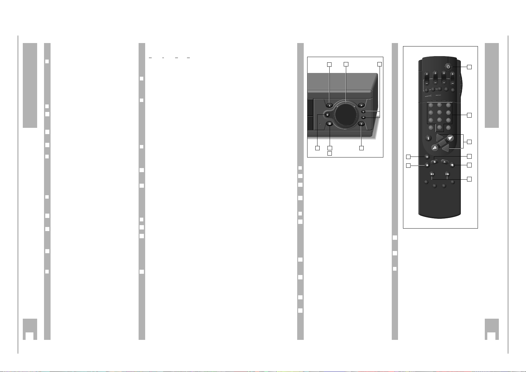
Allgemeiner Teil / General
GRUNDIG Service 1 - 19
14
Playback
Adjusting picture/sound quality
❒
Adjusting picture/sound quality –
automatic
After having inserted a cassette and started playback, the recorder adjusts automatically for the best
possible picture quality (Auto Tracking).
– During this adjustment the display »
AUTO-
TRACK
« appears on the recorder and the pictu-
re/sound quality may change.
❒
Adjusting picture/sound quality – manual
Press the
¢
TRACKING button.
– Display on recorder: »
TRACKING
«.
– Display on screen: »TRACKING«.
Carry out tracking (track position) adjustment using
the
F E
buttons on the remote control.
Store the setting using the Gbutton.
❒
Optimizing the picture/sound quality for
cassettes recorded on another recorder
If the picture jumps or scrolls when playing back
tapes recorded on another recorder, press the
¢
CODE button, the numbered buttons
8511
and the Gbutton.
– Brief display on recorder: »ON«.
❒
Optimizing the freeze-frame picture
If the picture jitters or flickers during the freezeframe playback function it can be optimized.
Press the h button when the freeze-frame picture
is on the screen.
Use the D button to select the »Jitter Adjustment«
line and call it up using the G button.
– Display on recorder: »
JITTER
«.
– Display on screen: »JITTERADJUSTMENT«.
Use the
D or C
button to adjust the picture to the
best subjective quality and then press the Gbutton.
❒
Optimizing the picture definition
(Automatic Contour Control Plus)
After having inserted a cassette and started playback, the recorder adjusts automatically for optimal
picture definition.
3
2
1
3
2
1
Locating a certain recording
V
ideo Index Such System (VISS)
This system allows you to locate the beginning of
any of your own recordings quickly and accurately.
❒
Marking a tape position – automatic
The “marks” are automatically placed on the tape –
at the beginning of each of your own recordings.
❒
Marking a tape position – manual
In addition to the automatic “marks”, it is also possible to place “marks” on the tape using the buttons.
Press the
¢
INDEX MARK button during recording or
playback at the position on the tape which is to be
“marked”.
– Display on recorder: »
INDEX MARK
«.
– Display on screen: »INDEX MARK«.
❒
Locating a tape position
The starting point is the current tape position.
Search is possible to the 9 previous or 9 following
marks.
Press the
¢
INDEX button.
– Display on recorder: »
INDEX
« and a number.
– Display on screen: »INDEX« and a number.
Use the numbered buttons 1…9 to enter a num-
ber – for the mark 1 to 9 – an then press the Y or
X button, or
turn the shuttle ring to the left or right.
– The tape is wound to the selected mark and play-
back is started there.
❒
Erasing a mark from the tape
Press the
¢
INDEX button.
Use the numbered buttons 1…9 to enter a number – for the mark 1 to 9 – and then press the Y or
X button, or
turn the shuttle ring to the left or right.
– The tape is wound to the selected mark and play-
back is started there.
– Flashing display on recorder: »
INDEX
«.
While the »
INDEX
« display is flashing it is possible
to erase the mark using the
¢
INDEX ERASE button.
– Display on recorder: »
INDEX ERASE
«.
– Display on screen: »INDEX ERASE«.
3
2
1
2
1
15
❒
Preparation
Switch the TV set on.
Select the programme position for the video recor-
der at the TV set (AV programme position).
Insert a cassette with sufficient playing time into
the cassette compartment.
❒
Operation
Select programme position, step by step using the
DC buttons on the remote control or the ab
buttons on the recorder;
directly using the numbered buttons 1 ... 0 on
the remote control.
w
!
For two-digit programme positions, press the
second numbered button directly after the first.
Start recording. To do this press the K button on
the remote control or the M button on the recorder for a longer period.
Select recording pause using the U button on the
remote control or the U button on the recorder.
Continue recording using the K button on the
remote control or the M button on the recorder.
End recording using the H button on the remote
control or the i button on the recorder.
Fast forward/rewind. To do this, with the stop
function selected, press the Y or X button on the
remote control, or
turn the shuttle ring to the right or left.
End winding using the H button on the remote
control or the i button on the recorder.
5
4
3
2
1
3
2
1
Eject the cassette. To do this press the N button
on the remote control or the P button on the
recorder.
Switch the recorder off using the A button on the
remote control or the i button on the recorder.
❒
Megalogic function
If the recorder is connected to a TV set with Megalogic functions, it is possible to record the TV programme which is visible on the TV screen by pressing the K button on the remote control or the M
on the recorder.
The programme position need not be selected on
the recorder.
7
6
Recording
➡
At a glance
6
5
2
1
43
7
1
1
6
5
3
2
4
7
DAY START
PROG.
ON/OFF
SP/LP
CLEAR
SET/CHECK
TIMER
2
3
1
5
6
4
8
9
7
0
AVVPT
+
+
I
N
D
OK
-
E
X
IN
D
E
E
S
X
A
R
M
E
A
X
R
E
K
D
I
N
STOP
SV/V+
G
N
I
K
C
A
R
T

Allgemeiner Teil / General
1 - 20 GRUNDIG Service
24
Special Functions
The child lock
It is possible to lock all functions using the child
lock.
Even a cassette which is inserted later must remain
in the recorder until it is unlocked.
❒
Activating the child lock
Call up the info table using the h button.
Use the DC buttons to select the » Child lock «
line and call it up using the G button.
– The » Child lock« table appears.
Enter a four-digit code number using the numbered
buttons 1 … 0 and confirm it using the G but-
ton.
– The recorder switches the table off.
– Display at recorder: »
LOCKED
« and the time.
w
!
The recorder is locked.
w
!
If you forget or lose the code number, your dealer
can assist you.
❒
Deactivating the child lock
Press any button.
– The » Child lock « table appears. In place of the
code number, »
****
« appears in the table.
Enter the four-digit code number using the numbered buttons 1 … 0 and confirm it using the G
button.
– The recorder switches the table off, the lock is
deactivated.
2
1
3
CODE NUMBER: ––––
–––––––––––––––––––
0-9 OK i
2
1
Setting the function display
(OSD – O
N SCREEN DISPLAY)
It is possible to adjust the duration of the function
displays which appear on the TV screen.
❒
Example
Call up the info table using the h button.
Use the DC buttons to select the »Info Duration«
line and call it up using the G button.
– The » Info Duration« table appears.
Select the desired setting using the DC buttons
and confirm it using the G button.
End the setting using the
¢
8
button.
4
3
OSD OFF
OSD 5 SECONDS
OSD PERMANENT
–––––––––––––––––––
po OK i
2
1
25
Special Functions
❒
Remote control of two recorders
When the switch is in the VIDEO 2 position, you can
control your GV 500;
When the switch is in the VIDEO 1 position, you can
control the second recorder.
w
!
If the 1 VIDEO 2 switch is not set to the selected
VCR address when controlling your GV 500, the
indication »
VID I
« or »
VID 2
« on the recorder
advises you that you must switch the remote
control to the other VCR address.
1
2
TV
1
2
TV
SP/LP
ON/OFF
CLEAR
SV/V+
STOP
ART
9
3
6
2
2
1
Remote control of other GRUNDIG
video recorders
With this remote control you can control different
GRUNDIG video recorders independently of each
other.
You can use it with your GV 500 and a second
recorder from the series VS 600 to VS 900 and the
GV 200 and later models.
The GV 500 must be adapted in order for the recorders to respond correctly to the remote control
commands.
❒
Preparation
Switch the TV set on.
Select the programme position for the video recor-
der at the TV set (AV programme position).
❒
Selecting the VCR address for the GV 500
Call up the info table using the h button.
Use the DC buttons to select the » Installation «
line and call it up using the G button.
Use the DC buttons to select the »VCR address«
line and call it up using the G button.
– The »VCR address« table appears.
Select VCR address 2 using the FEbuttons.
Confirm the setting using the G button.
– The recorder switches the table off.
5
4
VCR address:
1 2
–––––––––––––––––––
iu OK i
3
2
1
2
1
VIDEO 1
VIDEO 2
TV
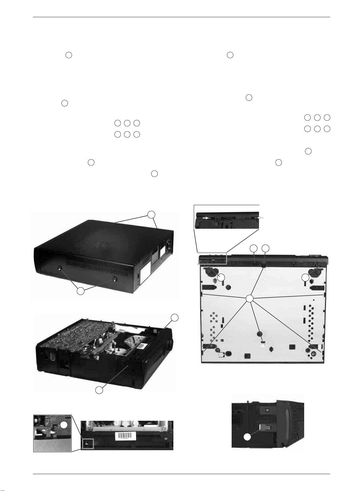
Allgemeiner Teil / General
Servicehinweise
1. Entfernen der Gehäuseteile
1.1 Gehäuseoberteil
– 4 Schrauben A herausdrehen (Fig. 1).
– Seitenteile des Gehäuseoberteils vorsichtig etwas auseinanderzie-
hen, dabei Gehäuseoberteil ca. 3cm nach hinten schieben und
abnehmen.
1.2 Bodenblech
– Bei Geräten mit großen Gerätefüßen:
– Befestigungsschraube je Gerätefuß herausdrehen
– Gerätefüße abnehmen.
– Rastnasen B lösen (Fig. 2) und Bodenblech abnehmen.
1.3 Frontblende
– Jog/Shuttle-Drehknöpfe abziehen (nur bei 38cm breiten Geräten)
– Bei 32cm breiten Geräten Rasthaken C / D / F (Fig.2 / 3) lösen
und Frontblende abnehmen.
Bei 38cm breiten Geräten Rasthaken C / E / F (Fig.2 / 3) lösen
und Frontblende abnehmen.
– Gegebenenfalls Steckverbindung lösen.
Hinweis zum Zusammenbau: Beim Aufstecken der Frontblende
von vorne auf das Gerät ist die Cassettenklappe so nach innen zu
drücken, daß der Hebel G in die Führung (Fig. 4) der Cassettenklappe eintaucht.
Bei Geräten mit einer Frontklappe muß die Massefeder H gemäß
Fig. 5 angebracht sein.
1.3.1 Frontklappe
– 2 Scharnierstifte in die angegebene Richtung schieben (Fig. 2).
– Frontklappe halb öffnen und abnehmen.
Service Instructions
1. Removing the Cabinet Parts
1.1 Cabinet Upper Part
– Undo 4 screws A (Fig. 1).
– Pressing the side panels carefully apart push the upper part of the
cabinet towards the rear by approx. 3cm and remove it.
1.2 Bottom Panel
– Machines with large feet:
– Undo the screw in each foot
– Take off the feet.
– Release the locking lugs B (Fig. 2) and remove the bottom panel.
1.3 Front Panel
– Pull of the Jog/Shuttle rotary knobs (only VCRs 38cm in width)
– On VCRs having a width of 32cm release the catches
(Fig. 2 / 3) and remove the front panel.
On VCRs having a width of 38cm release the catches C
(Fig. 2 / 3) and remove the front panel.
– Unplug the connector if necessary.
Note: When attaching the front panel from the front to the video
recorder press the cassette lid inwards so that the lever G engages
with the guide (Fig. 4) of the cassette lid.
On VCRs with front flap the earth spring H must be fitted as shown
in Fig. 5.
1.3.1 Front Flap
– Push the 2 hinge pins in the direction of the arrows (Fig. 2).
– Open the front flap halfway and remove it.
C
/ D /
/ E /
F
F
A
E
D
CC
A
B
Fig. 1
F
Fig. 2
F
Fig. 3
G
H
Fig. 4
GRUNDIG Service 1 - 21
Fig. 5

Allgemeiner Teil / General
2. Ausbauhinweise
2.1 Bedieneinheit ausbauen
– Rastnasen I lösen (Fig. 9 / 10) und Bedieneinheit abnehmen.
– Gegebenenfalls Steckverbindung lösen.
2.1.1 Bedieneinheit II (mit Tastatur – Fig. 10) ausbauen
– Rastnasen J lösen (Fig. 10) und Bedieneinheit II abnehmen.
2.1.2 Bedieneinheit II (mit Jog/Shuttle – Fig. 8) ausbauen
– Jog/Shuttle-Drehknöpfe bzw. Drehscheibe abziehen.
– Schrauben K herausdrehen und Bedieneinheit II abnehmen (Fig. 8).
2.2 Chassisplatte ausbauen
– Rastnasen N lösen und Chassisplatte herausnehmen (Fig. 6).
– Gegebenenfalls Steckverbindungen lösen.
Servicestellung:
Chassisplatte in die vorgesehenen Aussparungen O stecken (Fig. 11).
Achten Sie nach dem Austausch darauf, daß…
…das EPROM IC7801 bestückt ist.
…das Verbindungskabel zwischen dem Tuner und dem Modulator
angeschlossen ist.
…aus Sicherheitsgründen (VDE) die Modulatorabdeckung ange-
bracht ist.
Führen Sie die Abgleichschritte gemäß Kapitel 3 durch.
2. Disassembly Instructions
2.1 Removing the Keyboard Unit
– Release the locking lugs I (Fig.9/10) and withdraw the Keyboard Unit.
– Unplug the connector if necessary.
2.1.1 Removing the Keyboard Unit II (with Keyboard – Fig. 10)
– Release the locking lugs J (Fig. 10) and withdraw the Keyboard Unit II.
2.1.2 Removing the Keyboard Unit II (with Jog/Shuttle – Fig. 8)
– Pull off the Jog/Shuttle rotary knobs or rotary disc.
– Undo the screws K and withdraw the Keyboard Unit II (Fig. 8).
2.2 Removing the Family Board
– Release the locking lugs N and remove the Family Board (Fig. 6).
– Unplug the connectors if necessary.
Service Position:
Insert Family Board into the cut-outs provided O (Fig. 11).
After replacement ensure that:
…the EPROM IC7801 is fitted.
…the connecting cable between the tuner and the modulator is
connected.
…for safety reasons (VDE) the cover of the modulator is fitted.
Carry out the alignment procedures described in chapter 3.
N
Fig. 6
I I
Fig. 9
Fig. 7
Q
P
K
Fig. 8
O
I
J
I
I
Fig. 10 Fig. 11
1 - 22 GRUNDIG Service
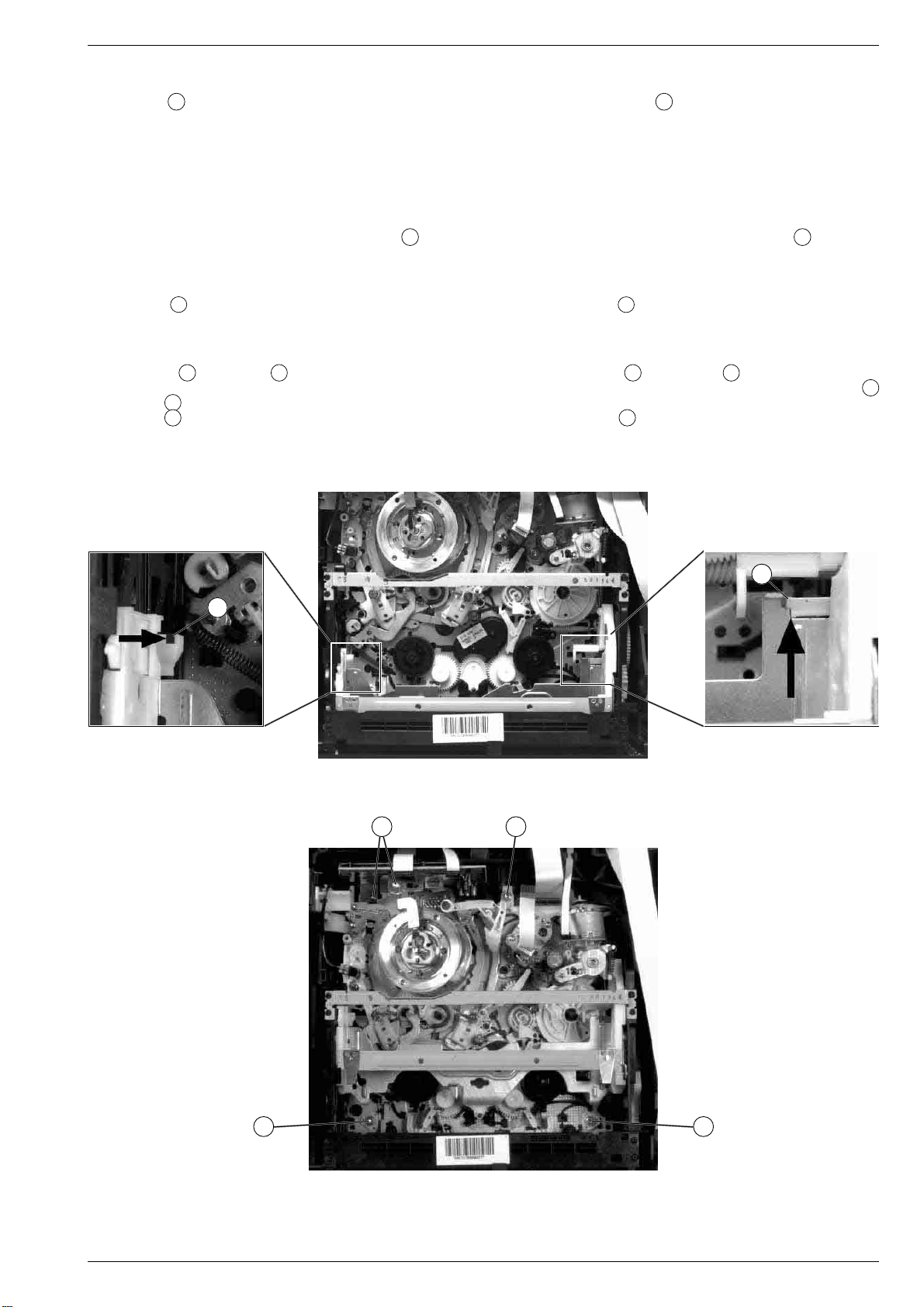
Allgemeiner Teil / General
2.3 Netzteilbaustein ausbauen
– Chassisplatte ausbauen.
– Rastnasen P ausrasten und Netzteilbaustein herausnehmen
(Fig. 7).
– Gegebenenfalls Steckverbindungen lösen.
2.3.1 Reparaturen im Netzteil
Bei Reparaturen des Netzteilbausteins Trenntrafo benutzen!
Sollen Bauteile im nicht netzgetrennten Teil des Netzteils ausgetauscht werden, müssen Sie den Abschirmdeckel abnehmen.
Achten Sie nach der Reparatur darauf, daß der Abschirmdeckel
des Netzteilbausteins sowie die Kunststoffabdeckung Q (Fig. 7)
angebracht sind!
2.4 Kopfverstärkerplatte ausbauen
– Chassisplatte ausbauen.
– Schrauben T herausdrehen, Steckverbindungen lösen und
Kopfverstärkerplatte nach oben herausziehen (Fig. 14).
2.5 Laufwerkausbau
– Chassisplatte ausbauen.
– Arretierungen R (Fig. 12) und S (Fig. 13) des Cassettenschach-
tes lösen und diesen dabei so weit nach innen schieben, bis die
Schrauben U (Fig. 14) zugänglich sind.
– Schrauben U herausdrehen (Fig. 14) und gegebenenfalls Steck-
verbindungen zur Elektronik lösen.
2.3 Removing the Power Supply Board
– Remove the Family Board.
– Release the locking lugs P and take out the Power Supply Board
(Fig. 7).
– Unplug the connectors if necessary.
2.3.1 Repairs within the Power Supply Unit
Use an isolating transformer when repairing the Power Supply Unit!
For replacement of components in the non-isolated circuits of the
Power Supply Unit remove the shielding cover.
On completion of the repairs ensure that the shielding cover of
the power supply module and the plastic cover Q (Fig. 7) are
refitted!
2.4 Removing the Head Amplifier Board
– Remove the Family Board.
– Undo the screws T, unplug the connectors and raise the Head
Amplifier Board to remove it (Fig. 14).
2.5 Removing the Drive Mechanism
– Remove the Family Board.
– Release the locks R (Fig. 12) and S (Fig. 13) of the cassette
compartment and move it inwards to gain access to the screws
(Fig. 14).
– Undo the screws U (Fig. 14) and unplug the connectors to the
electronics if necessary.
U
Fig. 12
S
R
Fig. 13
T
U
UU
Fig. 14
GRUNDIG Service 1 - 23

Allgemeiner Teil / General
3. Wichtige Masseverbindungen!
Beim Zusammenbau des Gerätes ist darauf zu achten, daß die
Masseverbindungen zwischen Gehäuseboden und Modulator/Chassisplatte, Gehäuseboden und Netzteilbaustein, sowie Gehäuseboden
und Gehäuseoberteil gewährleistet sind.
4. Durchführen von Messungen
Bei Messungen mit dem Oszilloskop an Halbleitern sollten Sie nur
Tastköpfe mit 10:1 - Teiler verwenden. Außerdem ist zu beachten, daß
nach vorheriger Messung mit AC-Kopplung der Koppelkondensator
des Oszilloskops aufgeladen sein kann. Durch die Entladung über das
Meßobjekt können diese Bauteile beschädigt werden.
5. Meßwerte und Oszillogramme
Bei den in den Schaltplänen und Oszillogrammen angegebenen
Meßwerten handelt es sich um Näherungswerte!
6. Codeaufkleber
Alle wichtigen Komponenten des Gerätes (Laufwerk / Platinen) sind
mit einem Codeaufkleber versehen. Diese Aufkleber beinhalten die
Typenbezeichnung und Produktionsdaten (Seriennummer,
Produktioncode, Produktionsdatum, …).
Typenschild des Gerätes
Hinweis:
Bei wichtigen Änderungen erhöht sich der Produktionscode um eins.
1
Bestellnummer / Order number
Produktionsdatum / Production date
Produktionscode / Production code
TYPE
G.ME 07-00
WD05 045
220V-240V ~ 50Hz
3. WARNING: Chassis connections!
When re-assembling the machine it is essential to observe that the
chassis connections between the cabinet bottom and Modulator/
Family Board, cabinet bottom and Power Supply Board, cabinet
bottom and cabinet upper part are in good order.
4. Carrying out Measurements
When making measurements on semi-conductors with an oscilloscope, ensure that the test probe is set to 10:1 dividing factor. Further,
please note that if the previous measurement is made on AC input, the
coupling capacitor in the oscilloscope will be charged. Discharge via
the item being checked can damage components.
5. Measured Values and Oscillograms
The measured values given in the circuit diagrams and oscillograms
are approximates!
6. Code Labels
All important components of the video recorder (drive mechanism /
printed circuit boards) are provided with a code label. These adhesive
labels indicate the type of product and the production data (serial
number, production code, date of production, …).
Type Plate
Advice:
Important changes are indicated by increasing the change code by
one.
GV 500 SV
RP 500
SER.NR. 100547
Gerätetype / Type of product
Fernbedienung / Remote Control
Seriennummer / Serial number
01 37602 0 52 0 100547 6
Laufwerks-Codeaufkleber
Hinweis:
Der Produktionscode und die Seriennummer auf dem Codeaufkleber
des Laufwerks muß nicht mit dem Produktionscode und der Seriennummer auf dem Typenschild übereinstimmen.
0092714012345678
12345678 009271 TD-P2/0 9520 10WD40
Seriennummer / Serial number
Fabrikscode / Factory code number
Laufwerkstype / Type of drive mechanism
Platinen-Codeaufkleber
Hinweis:
Der Produktionscode ist nicht generell aufgedruckt. Bei wichtigen
Änderungen erhöht sich die letzte Ziffer der Fabrikscodenummer
(Punktnummer).
Code Label on the Drive Mechanism
Advice:
The production code and the serial number on the code label of the
drive mechanism do not necessarily agree with the production code
and the serial number on the type plate.
Produktionscode / Production code
Produktionsdatum / Production date
Code Label on the Printed Circuit Boards
Advice:
The production code is not generally printed on the label. Important
changes are indicated by increasing the last figure of the factory code
by one (figure following the point).
OFB22/2G125 63703 KW520 WD02 123456
Platinenbezeichnung / Name of PCB
Fabrikscode / Factory code number
1 - 24 GRUNDIG Service
Seriennummer / Serial number
Produktionscode / Production code
Produktionsdatum / Production date
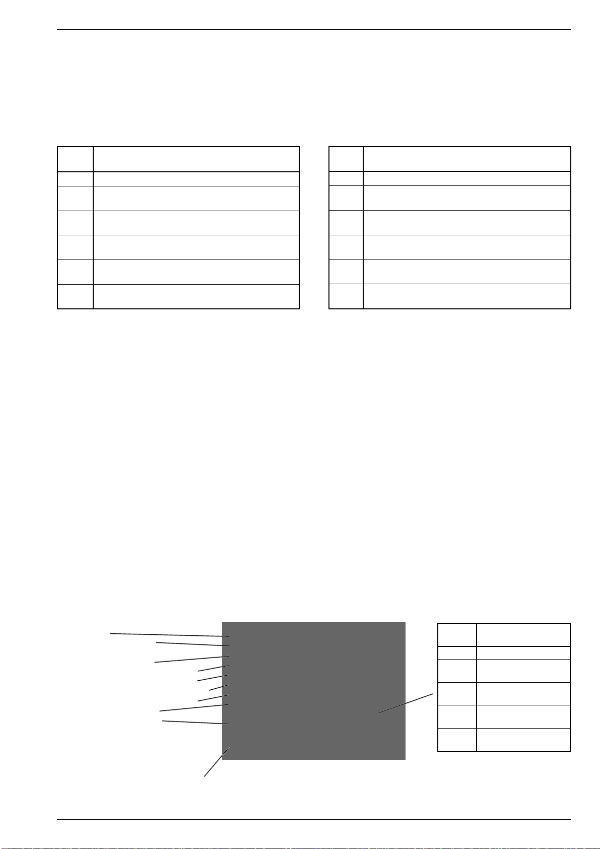
Allgemeiner Teil / General
Service- und Sonderfunktionen
1. Servicefunktionen
Aufrufen der Servicefunktionen
– Auf dem Fernbediengeber die Taste "CODE" drücken
– Codenummer eingeben
– Taste G drücken.
Code- Funktion
Nummer
4934 Aufruf des Servicetestprogrammes
4936 Kopfradlagengeber-Einstellung
(siehe Abgleich Kap. 2.1)
4937 RAM und EEPROM löschen
(siehe Servicetestprogramm Pkt. 1.2)
4938 "ACC (Automatic Contour Control) plus Studio Quality"
(siehe Abgleich Kap. 3)
4940 Fernbedienung des "Bildsuchlaufes" ist möglich
über die Tasten YX
4941 Fernbedienung der "Shuttle"-Funktionen ist möglich
über die Tasten YX
1.1 Servicetestprogramm
Die Anzeige der Daten des Servicetestprogrammes erfolgt zum einen
am Bildschirm des angeschlossenen Fernsehgerätes und zum anderen im Display des Videorecorders in vier Ebenen.
Aufruf, Ebenenkontrolle und Beenden des Servicetestprogrammes
Der Aufruf des Servicetestprogrammes ist bei allen Laufwerksfunktionen
möglich, jedoch nicht während der Einstellfunktionen (Sendersuchlauf, …). Während des Servicemodes bleibt das Gerät bei allen
Laufwerksfunktionen voll einsatzbereit.
• Aufruf des Servicetestprogrammes:
Mit dem Fernbediengeber folgendes ausführen:
– Taste "CODE" drücken
– Zahlenfolge 4 9 3 4 eingeben und mit G bestätigen
– Auf dem Display des Videorecorders erscheinen anschließend
die Werte der ersten Ebene (siehe Pkt. 1.1.2) und auf dem
Bildschirm des Fernsehgerätes alle Werte der vier Displayebenen (siehe Pkt. 1.1.1).
• Beenden des Servicetestprogrammes:
Taste A drücken oder Gerät vom Netz trennen.
Service and Special Functions
1. Service Functions
Calling up the Service Functions
– Depress the "CODE" button on the remote control
– Feed in the code number
– Depress the G button.
Code Function
Number
4934 Service Test Programme
4936 Gap position adjustment
(see Adjustment Procedures, chap. 2.1)
4937 Clearing RAM and EEPROM
(see Service Test Programme para. 1.2)
4938 "ACC (Automatic Contour Control) plus Studio Quality"
(see Adjustment Procedures, chap. 3)
4940 Remote control of the "picture search" function is
possible with the buttons YX
4941 Remote control of "Shuttle" functions is possible
with the buttons YX
1.1 Service Test Programme
The data of the service test programme are indicated on the screen of
the connected television receiver as well as on the display of the video
recorder at four levels.
Calling up, Checking the Levels of and Terminating the Service
Test Programme
The service test programme can be called from any tape drive function other
than the data entry functions (station search, …). While it is operating in the
service mode, the VCR remains fully operational in all tape drive functions.
• Calling up the Service Test Programme:
On the remote control handset:
– Press the "CODE" button
– Enter the numbers 4 9 3 4 successively and confirm with G
– The display of the video recorder will then show the values of the
first level (see para 1.1.2) and the screen of the television receiver
all values of the four display levels (see para 1.1.1).
• Terminating the Service Test Programme:
Press the A button or disconnect the video recorder from the mains.
1.1.1 Bildschirmanzeige des Servicetestprogramms
Nach dem Aufruf des Servicetestprogrammes werden am Bildschirm
des Fernsehgerätes alle Werte des Servicetestprogrammes angezeigt.
Fehler / Error
Fehlerstatus / Error Status
Laufwerksensoren / Tape Deck Sensors
– Init Schalter / Init Switch
– Fädeltacho / Threading Tacho (FTA)
– Bandende / Tape End Sensor (TAE)
– Bandanfang / Tape Begin Sensor (TAS)
– Aufnahmesperre / Record Protection
– Wickeltacho / Reel Tacho
Maskennummern / Mask No.
– Bedienrechner / Keyboard Control µC
(IC7101) "ODPU-2U"
– Ablaufsteuerung / Sequence Control
(IC7801) "ODCG1-1U"
– TVC (IC7410) "OTDP3-1U"
Betriebsstundenzähler / Operating Hours
Tiefergehende Informationen entnehmen Sie bitte dem Kapitel
"1.1.2 Displayanzeige des Servicetestprogrammes".
GRUNDIG Service 1 - 25
ERROR: NO ERROR
ERR STAT: BEREITSCHAFT
INIT SWITCH 0
THREADING TACHO 0
TAPE END SENSOR 1
TAPE BEGIN SENSOR 1
RECORD PROTECTION 0
REEL TACHO L:1 R:0
TAPE DECK STATUS: 08
ODCG1-1U ODPU-2U
OTDP3-1U
OPERATING HOURS: 1974
1.1.1 Service Test Programme Indication on TV
When calling up the service test programme all values of this programme are indicated on the TV screen.
Code Laufwerkstellung /
Tape Deck Position
05…09 Auswurf / Eject
5C…5E Index, Vorlauf, Rücklauf /
Index, wind, rewind
64…67 Ausgefädelt-Stop /
Stop threaded out
D4…D8 Wiedergabeposition /
Play position
ED…EF Wiedergabe rückwärts /
Play reverse
For more detailed information please see chapter "1.1.2 Service Test
Programme Indication on VCR".
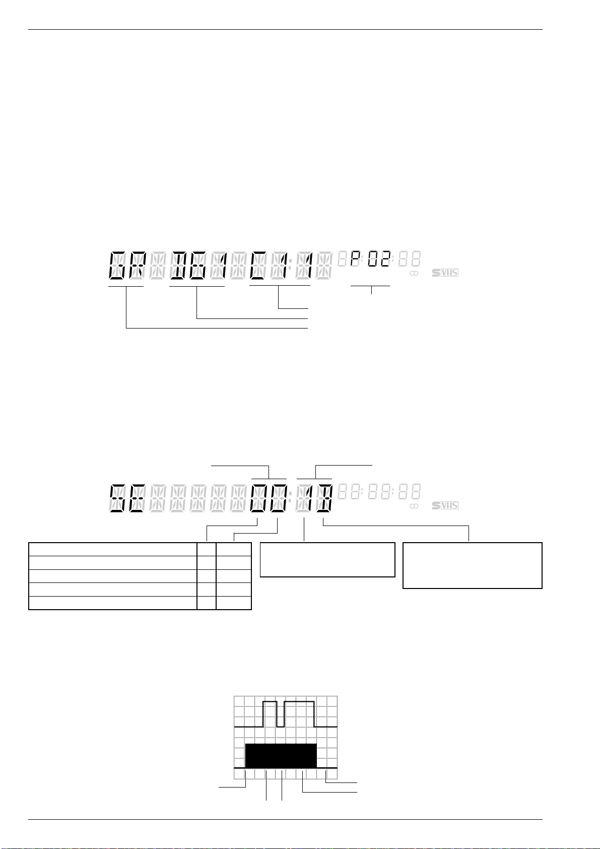
Allgemeiner Teil / General
1.1.2 Displayanzeige des Servicetestprogrammes
Ebenenkontrolle der Displayanzeige
Die Displayanzeige des Servicetestprogrammes besteht aus vier
Ebenen:
Ebene 1 – Masken- und Versionsnummern der µC
Ebene 2 – Laufwerksensoren
Ebene 3 – Fehlercode und Fehlerstatus
Ebene 4 – Betriebsstundenzähler.
Von einer Ebene zur anderen gelangt man durch Drücken der Taste G
auf der Fernbedienung. Nach der Ebene 4 folgt wieder die Ebene 1.
Ebene 1 der Displayanzeige
Masken- und Versionsnummern der µC
Das Display ist in vier optisch getrennte Zahlen- und Zeichenblöcke
unterteilt. Von links gelesen, Bedien-Version, Laufwerksrechner "TVC",
Ablaufsteuerung und Bedienrechner.
1.1.2 Service Test Programme Indication on VCR
Checking the Levels of the Display Indication
The indication of the service test programme on the VCR display
consists of four levels:
Level 1 – Mask and Version Numbers of the µC
Level 2 – Tape deck sensors
Level 3 – Error code and error status
Level 4 – Operating hours meter.
The levels can be changed step by step by pressing the G button on
the remote control handset. Level 4 is again followed by Level 1.
Level 1 of the Display Indication
Mask and Version Numbers of the µC
The display is optically subdivided into four blocks of figures and
characters. From left to right, Keyboard control version, Tape Deck µC
"TVC", Sequence Control and Keyboard control µC.
VPSPDC
MAN
LP
STOP TIMER 1 2
Bedienrechner (IC7101) / Keyboard control µC (IC7101)
Ablaufsteuerung (IC7801) / Sequence Control (IC7801)
Laufwerksrechner "TVC" (IC7410) / Tape Deck µC "TVC" (IC7410)
Bedien-Version / Keyboard control version
Ebene 2 der Displayanzeige
Laufwerkstellungen und Kontrolle der Laufwerksensoren (Überprüfung ohne Cassette)
Die Anzeige zur Kontrolle der Laufwerksensoren erfolgt 4-stellig. Die
linken zwei Digitalstellen zeigen die Laufwerkstellung an, in der sich
der Cassettenschacht und die Fädelschlitten befinden.
In den rechten zwei Digitalstellen werden mehrere Sensoren angezeigt.
Mit jeder Betätigung der Sensoren ändert sich der Wert der Anzeige.
Laufwerkstellung / Tape drive state Laufwerksensoren / Tape deck sensors
Auswurf / Eject 0 5…9
Index, Vorlauf, Rücklauf / Index, wind, rewind 5 C / D / E
Ausgefädelt-Stop / Stop threaded out 6 4…7
Wiedergabeposition / Play position D 4…8
Wiedergabe rückwärts / Play reverse E D / E / F
Laufwerkstellung und Funktion des Init Schalters
Das Diagramm zeigt die Funktion des Init-Schalters in Abhängigkeit von
der Stellung des Laufwerks. Dafür ist die Anzahl der Fädeltachoimpulse
(FTA) wichtig. Diese Impulse erzeugt der Fädeltachogeber (Flügelrad),
der mechanisch mit dem Fädelmotor verbunden ist.
Level 2 of the Display Indication
Checking the Tape Deck Positions and the Deck Sensors (without
a cassette loaded)
The tape deck sensors can be checked by a four-place indication. The
two digital places on the left for the tape drive state indicate the position
of the cassette compartment and the threading roller units.
The two digital places on the right indicate several sensors. The
indicated value changes with each operation of a sensor.
STOP TIMER 1 2
Init Schalter / Init switch
Fädeltacho / Threading tacho (FTA)
Wickeltacho links / Left reel tacho
Tape Deck Position and Function of the Init Switch
The diagram shows the function of the Init switch dependent on the
tape deck position. For this, the number of the threading tacho pulses
(FTA) is important. These signals are generated by the threading tacho
generator (butterfly sensor) which is mechanically connected with the
threading motor.
VPSPDC
MAN
LP
Bandende / End of tape (TAE)
Bandanfang / Beginning of tape (TAS)
Aufnahmesperre / Record protection
Wickeltacho rechts / Right reel tacho
A: AC, 2V/Div, 0,5s/Div
B: AC, 2V/Div, 0,5s/Div
Cassette eingeschoben / Cassette in
Cassette unten / Cassette down Index, Umsspulen / Index, wind-rewind
1 - 26 GRUNDIG Service
A
B
Init Schalter / Init switch
Fädeltacho-Impuls (FTA)
Threading pulse (FTA)
Wiedergabe / Play
Einfädeln / Thread in

Allgemeiner Teil / General
Ebene 3 der Displayanzeige
Fehlerstatus und Fehlercodes
Der zuletzt aufgetretene Fehlerstatus und Fehlercode wird im UhrRAM gespeichert und bleibt auch dann erhalten, wenn das Gerät vom
Netz getrennt wird. Löschen kann man diesen im Servicemode durch
Drücken der Taste "CLEAR" auf dem Fernbediengeber.
Laufwerk Fehlercode / Drive Mechanism Error Code
0 Kein Fehler / No error
1 Fädelfehler / Threading error
2 Kein Capstantacho / No capstan tacho
3 Band gerissen / Tape torn
Laufwerk Fehlerstatus / Drive Mechanism Error Status
000 Bereitschaft - kein Fehler / Standby - no error
012 Bereitschaft / Standby
014 Autotracking
031 Wiedergabe rückwärts (3-fach) / Play reverse (3x)
034 Wiedergabe rückwärts (langsam) / Play reverse (slow)
041 Standbild / Still
042 Bildsuchlauf vorwärts (2-fach) / Picture search forward (2x)
044 Bildsuchlauf rückwärts (9-fach) / Picture search reverse (9x)
045 Cassettenausgabe / Eject
046 Bildsuchlauf vorwärts (9-fach) / Picture search forward (9x)
047 Wiedergabe rückwärts / Play reverse
048 Aufnahme - Pause / Record - Pause
050 Rücklauf / Rewind
052 Vorlauf / Wind
053 Wiedergabe / Play
054 Stop
055 Aufnahme / Record
112 Nächster Index / Next index
113 Vorheriger Index / Previous index
114 Indexmarken setzen / Inserting index marks
115 Indexmarken löschen / Clearing index marks
130 ATTS
168 Einzelbildfortschaltung vorwärts / Frame forward
169 Einzelbildfortschaltung rückwärts / Frame reverse
170 Bildsuchlauf rückwärts (11-fach) / Picture search reverse (11x)
Level 3 of the Display Indication
Error Status and Error Codes
The last error status and error code that occurred is stored in the Timer
RAM and is saved even if the VCR is disconnected from the mains. To
erase the data, press the "CLEAR" button on the remote control while
in the service mode.
4 Fehlender Wickeltacho links / Missing left reel tacho
5 Fehlender Wickeltacho rechts / Missing right reel tacho
6 Kopfscheibenmotorfehler / Headwheel motor error
VPSPDC
MAN
LP
STOP TIMER 1 2
171 Bildsuchlauf rückwärts (7-fach) / Picture search reverse (7x)
172 Bildsuchlauf rückwärts (5-fach) / Picture search reverse (5x)
173 Bildsuchlauf vorwärts (5-fach) / Picture search forward (5x)
174 Bildsuchlauf vorwärts (7-fach) / Picture search forward (7x)
175 Bildsuchlauf vorwärts (11-fach) / Picture search forward (11x)
197 Bereitschaft-Schacht oben / Standby Eject
199 Nachvertonen / Audio Dubbing
202 Nachvertonen - Pause / Audio Dubbing Pause
211 Zeitlupe (1/24) / Slow (1/24)
212 Zeitlupe (1/14) / Slow (1/14)
215 Zeitlupe (1/7) / Slow (1/7)
216 Zeitlupe (1/2) / Slow (1/2)
217 Zeitlupe rückwärts (1/24) / Slow reverse (1/24)
218 Zeitlupe rückwärts (1/14) / Slow reverse (1/14)
219 Zeitlupe rückwärts (1/7) / Slow reverse (1/7)
220 Zeitlupe rückwärts (1/2) / Slow reverse (1/2)
222 Synchro-Edit-Aufnahme / Synchro-Edit-Record
223 Kopfradlagengeberabgleich / Auto Gap Position Alignment
239 ACC+ Abgleich / ACC+ alignment
246 Synchro-Edit-Pause
247 Zeitlupe (1/10) / Slow (1/10)
248 Zeitlupe (1/18) / Slow (1/18)
249 Zeitlupe rückwärts (1/10) / Slow reverse (1/10)
250 Zeitlupe rückwärts (1/18) / Slow reverse (1/18)
Überwachung der Laufwerksfunktionen
Für die Überwachung der Laufwerksfunktionen sind am Laufwerk
Sensoren angebracht. Diese liefern entsprechend der Gerätefunktion
folgende Tachosignale
– WTL / WTR – Wickelteller links / rechts
– FTA – Fädeltacho
– FG – Capstanmotor
– PG/FG – Kopfscheibenmotor.
Fehlt bei der Ansteuerung des Laufwerks ein Tachosignal, dann
versucht das Gerät, den Cassettenschacht in die Stellung "EJECT" zu
bringen.
GRUNDIG Service 1 - 27
Monitoring the Tape Deck Functions
For monitoring the tape deck functions the tape deck is fitted with
sensors which supply the following tacho signals according to the
functions:
– WTL / WTR – reel left / right
– FTA – threading tacho
– FG – capstan motor
– PG/FG – headwheel motor
When one tacho pulse is missing during the operation of the tape deck,
the VCR tries to move the cassette compartment to the "EJECT"
position.
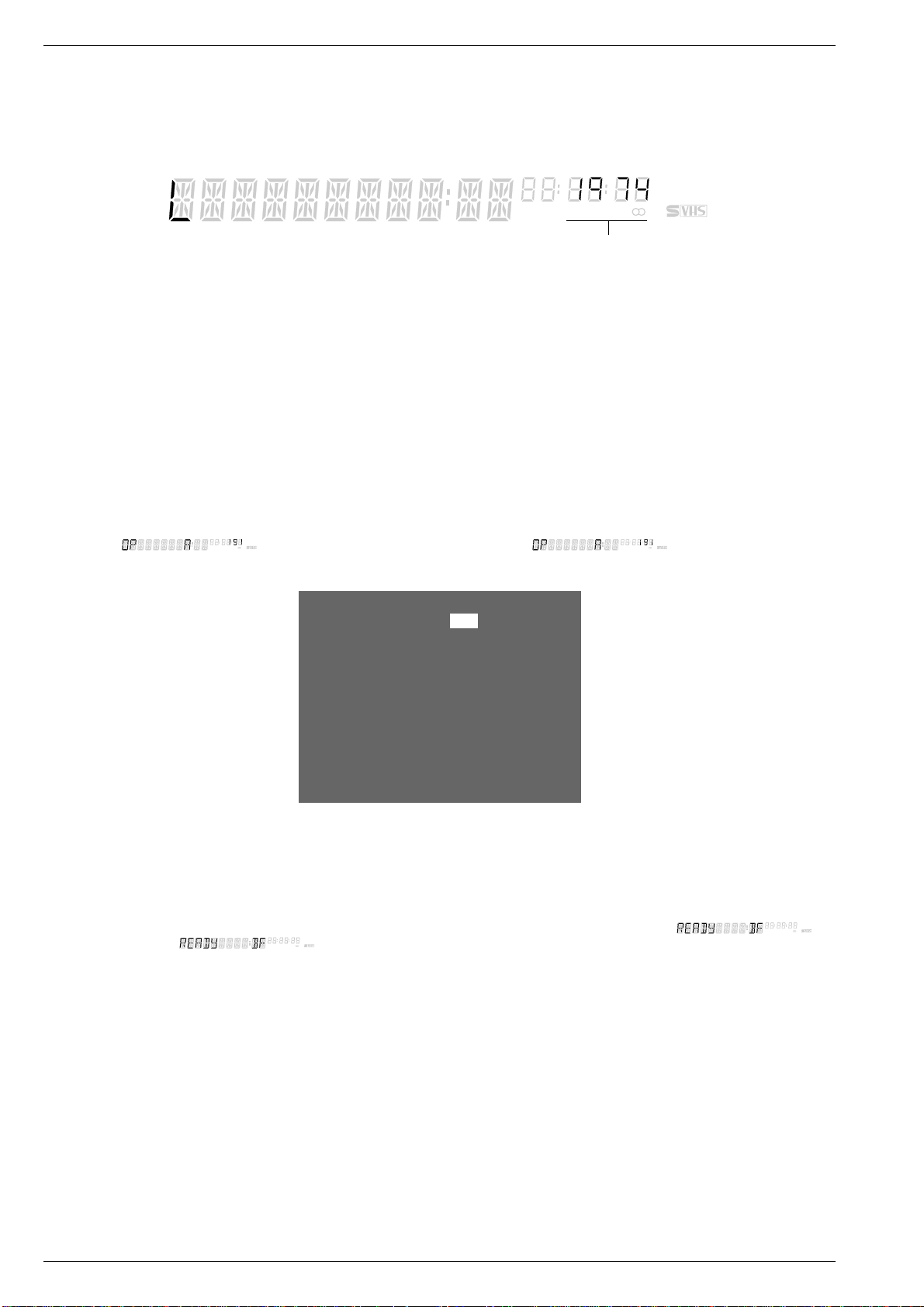
Allgemeiner Teil / General
Ebene 4 der Displayanzeige
Betriebsstundenzähler
Der Betriebsstundenzähler gibt an, wieviele Stunden die Kopfscheibe
rotierte.
Hier ist zum Beispiel, die Kopfscheibe 1974 Stunden lang gelaufen.
1.1.3 Geräte-Optionscode
Mit dem Geräte-Optionscode "A"…"F" wird gemäß dem Geräteaufbau
die entsprechende Software in den maskenprogrammierten µCs aktiviert. Der Optionscode wird im EEPROM gespeichert.
Alle nachfolgenden Schritte sind mit der Fernbedienung auszuführen:
– Servicetestprogramm aufrufen:
– Taste "CODE" drücken
– Zahlenfolge 4 9 3 4 eingeben und mit G bestätigen
– Optionscodeeingabe aufrufen:
– Taste "CODE" drücken
– Zahlenfolge 4 9 4 9 eingeben und mit G bestätigen
– Am Bildschirm des Fernsehgerätes erscheinen zur Kontrolle an-
schließend die im EEPROM gespeicherten Optionscodes, "A"…"F".
Davon ist der für die Eingabe aktive Code invers dargestellt.
Dieser aktive Code wird zusätzlich auf dem Display des Gerätes
angezeigt (
eingabe ohne angeschlossenes Fernsehgerät möglich.
STOP TIMER 1 2
VPSPDC
MAN
LP
). Damit ist die Optionscode-
Level 4 of the Display Indication
Operating Hours Meter
The operating hours meter indicates the number of hours the headwheel has been rotating.
In the example below an operating time of 1974 hours is indicated.
VPSPDC
MAN
LP
STOP TIMER 1 2
Betriebsstundenzähler
Operating hours indication
1.1.3 VCR Option Code
The VCR option codes "A"..."F" serve the purpose of activating the
respective software stored in the mask-programmed µC of the different
versions of video recorders. The option code is stored in the EEPROM.
The following steps are exclusively carried out on the remote control:
– Call up the service test programme:
– Press the "CODE" button
– Enter the numbers 4 9 3 4 successively and confirm with G
– Call up the option code:
– Press the "CODE" button
– Enter the numbers 4 9 4 9 successively and confirm with G
– The option codes "A"…"F" stored in the EEPROM are then dis-
played on the TV screen as a check. The code active for being
entered is shown inversely.
This active code is additionally shown on the display of the video
recorder (
the option code without requiring a television set to be connected.
STOP TIMER 1 2
VPSPDC
MAN
LP
) so that it is possible to enter
OPTION A: 191
OPTION B: 009
OPTION C: 033
OPTION D: 032
OPTION E: 000
OPTION F: 001
_ _ _ _ _ _ _ _ _ _ _ _ _ _ _ _ _ _ _ _ _ _
34 0-9 OK i
– Eingabe der Optionscodes gemäß der Tabelle Geräte-Code-
nummern:
Achtung: Nur bei richtiger Optionscode-Eingabe sind alle Geräte-
funktionen gewährleistet.
– Optionscode "A", siehe Geräte-Codenummern (z.B. "191" für
GV 500 SV) eingeben und mit G bestätigen.
Im Display erscheint zur Kontrolle für ca. 2s der Optionscode
hexadezimal, z.B. "
STOP TIMER 1 2
VPSPDC
MAN
LP
" für GV 500 SV.
– Mit den Tasten CD ist die Anwahl der weiteren Optionscodes
möglich. Die Eingabeschritte der Optionscodes "B"…"F" sind
genauso durchzuführen wie beim Optionscode "A".
– Beenden der Optionscode-Eingabe durch Drücken der Tasten h
und anschließend A.
– Enter the option code as specified in the table "VCR Code Numbers"
Attention: All functions of the respective VCR will only be available
if the option code has been entered correctly.
– Enter the option code "A", see VCR Code Numbers (e.g. "191" for
GV 500 SV) and confirm with G.
The option code is then indicated on the display for approx. 2s in
hexadecimal form as a check, e.g. "
STOP TIMER 1 2
VPSPDC
MAN
LP
" for
GV 500 SV.
– The other option codes can be selected with the buttons CD.
The steps for entering the option codes "B"…"F" are the same as
for option code "A".
– To terminate the entry press the button h followed by A.
1 - 28 GRUNDIG Service

Allgemeiner Teil / General
Geräte-Codenummern
GV 500 SV
GV 500 SV/1
GV 500 GB
GV 510 SV
GV 530 SV
Option A 191 191 053 063 255 255 191 191 191 191 255 255 191 255
Option B 009 009 009 009 041 041 009 009 217 217 249 249 217 249
Option C 033 039 039 032 033 039 033 039 033 039 033 039 033 033
Option D 032 032 038 032 032 032 032 032 032 032 032 032 032 032
Option E 000 000 132 008 020 020 000 000 000 000 020 020 000 020
Option F 001 001 001 001 001 001 000 000 002 002 003 003 002 003
1.2 Löschen des RAMs und EEPROMs
Achtung:
Mit dieser Funktion wird das EEPROM gelöscht und initialisiert. Der
kundenspezifische Senderspeicher und das interne Prozessor-RAM
werden ebenfalls gelöscht (ausgenommen Laufwerkparameter und
Optionen).
Aufruf der RAM- und EEPROM-Löschfunktion
– Auf der Fernbedienung Taste "CODE" drücken
– Zahlenfolge 4 9 3 7 eingeben
– Taste G drücken.
Hinweis:
Nach dem Löschen bzw. dem Tausch des EEPROMs muß das Gerät
neu abgeglichen werden (siehe Abgleich, Kap. 3).
Nach dem Tausch des EEPROMs ist zusätzlich die Optionscodeeingabe erforderlich.
VCR Code Numbers
GV 530 SV/1
GV 5050 SV
GV 5050 SV/1
GV 5095 SV
GV 5095 SV/1
GV 5395 SV
GV 5395 SV/1
SE 5102 SV
SE 5104 SV
1.2 Erasing the RAM and EEPROM
Attention:
This function erases and initializes the EEPROM. The customised
station memory and the internal processor RAM are also erased (with
the exception of tape deck parameters and options).
Calling up the RAM and EEPROM Erase Function
– Press the "CODE" button on the remote control
– Enter the numbers 4 9 3 7 sequentially
– Press the G button.
Note:
After the EEPROM has been cleared or replaced the video recorder
must be realigned (see Adjustment, chapter 3).
Additionally, on replacement of the EEPROM, the option code must be
entered.
1.3 Löschen der kundenspezifischen Daten
Achtung:
Mit dieser Funktion werden alle kundenspezifische Daten (Uhrzeit,
Sendertabelle, Timer-Daten, …) gelöscht. Die gerätespezifischen
Daten bleiben erhalten.
Aufruf der Löschfunktion
Während dem Anschließen des Gerätes an das Netz eine Gerätetaste
mindestens 5s drücken.
1.4 Dauerlaufprüfung
Die Dauerlaufprüfung ist im Servicetestprogramm integriert. Diese hilft
Fehler zu finden, die sporadisch auftreten. Ein erkannter Fehler wird
im EEPROM gespeichert und bleibt erhalten, auch wenn das Gerät
vom Netz getrennt wird.
Aufruf der Dauerlaufprüfung
– Cassette einschieben.
– Dauerlaufprüfung im Servicetestprogramm starten mit einer der
Tasten K, T oder Y.
Anschließend durchläuft das Gerät die Dauerlaufprüfung entspre-
chend dem folgenden Schema.
Beenden der Dauerlaufprüfung
– Auf der Fernbedienung Taste A drücken oder Gerät vom Netz
trennen.
Wiedergabe
Play
T
1.3 Erasing the Customised Data
Warning:
This function erases all customised data (clock time, station table,
timer data, …). The specific data of the machine is not affected by this
function.
Calling up the Erase Function
Press any button on the video recorder for 5s at least while connecting
it to the mains.
1.4 Continuous Operation Test
The continuous operation test is part of the service test programme and
is used to find out occasionally occurring faults. The fault is stored in
the EEPROM and is saved even if the VCR is disconnected from the
mains.
Calling up the Continuous Operation Test
– Insert a cassette.
– Start the continuous operation test in the service test programme by
pressing one of the buttons K, T or Y.
The video recorder is then subjected to the continuous operation test
as shown in the diagram below.
Terminating the Continuous Operation Test
– Press the A button on the remote control or disconnect the video
recorder from the mains.
Bandende
End of Tape
Aufnahme
Record
K
Bandanfang
Beginning of
tape
GRUNDIG Service 1 - 29
Rückspulen
Rewind
Y
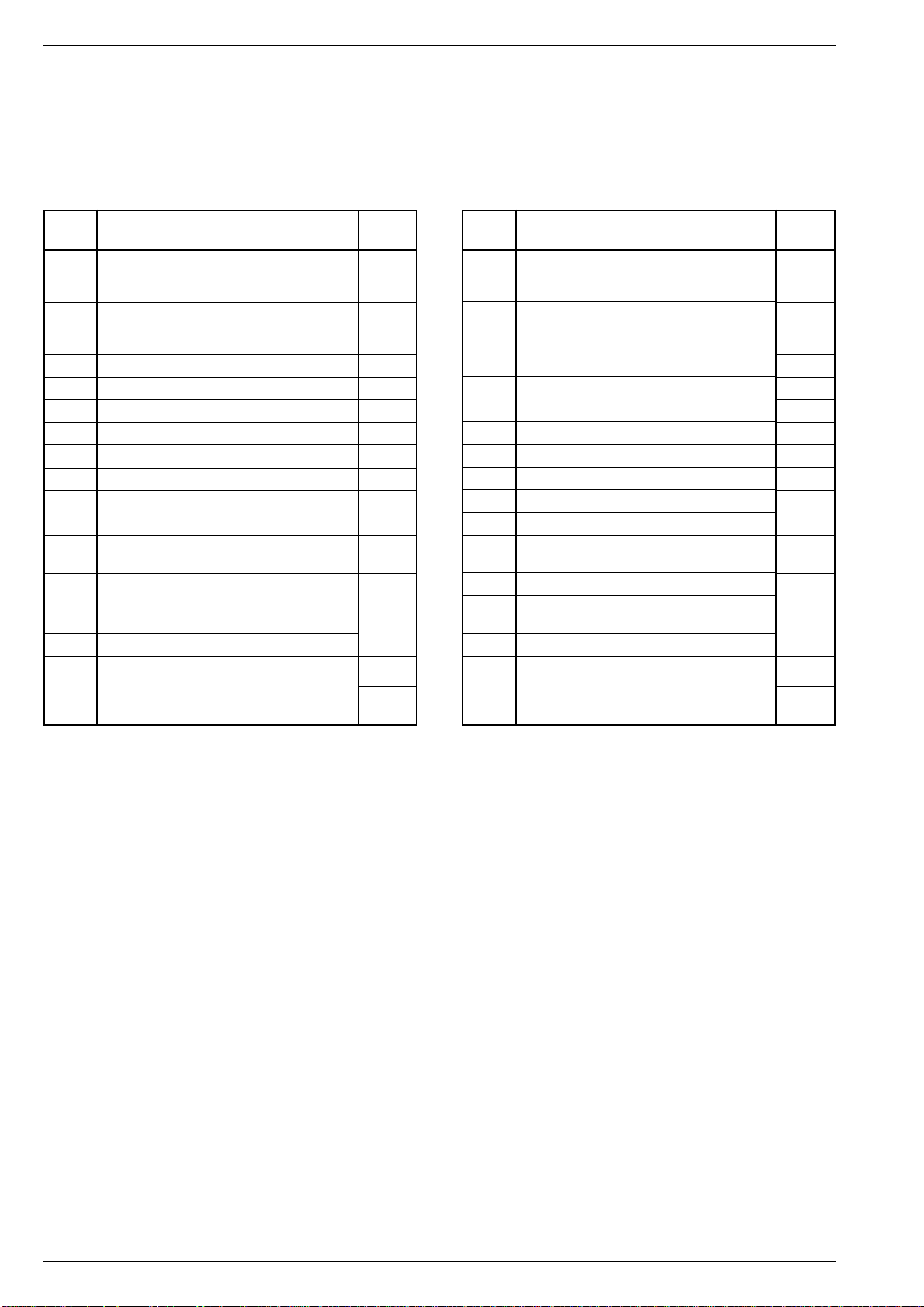
Allgemeiner Teil / General
2. Sonderfunktionen
Aufrufen der Sonderfunktionen
– Auf dem Fernbediengeber die Taste "CODE" drücken
– Codenummer eingeben
– Taste G drücken.
Löschen der Dauerlauffunktionen
– Taste A drücken, Sonderfunktion wird abgebrochen.
Code- Funktion
Nummer
8501 Dauerlauffunktion "Wiedergabe" bis zum
Bandzählerstand beim Dauerlaufbeginn.
Dauerlauf starten mit der Taste T.
8501 Dauerlauf "Aufnahme"
Programmplatz wählen (vor dem Aufruf der
Code-Nummer) und Taste K drücken.
8510 V-Impuls-Eintastung "AUS"
8511 V-Impuls-Eintastung "EIN"
8513 Durchschleifbetrieb (AV2 nach AV1) aktiviert
8514 Kein Durchschleifbetrieb (AV2 nach AV1)
8516 Bedienebene "VIDEO 1"
8517 Bedienebene "VIDEO 2"
8518 Modulator "AUS"
8519 Modulator "EIN"
8526 10- und 16 Bit-Geberbefehle werden
angenommen
8527 16 Bit-Geberbefehle werden angenommen
8528 Abgleich der V-Impuls-Eintastung
(Standbild optimieren)
8562 Piezo "AUS" (city line)
8563 Piezo "EIN" (city line)
Display
zeigt
C-PLAY
C-REC
OFF
ON
ON
OFF
VID 1
VID 2
OFF
ON
OFF
ON
JITTER
–
–
2. Special Functions
Calling up the Special Functions
– Press the "CODE" button on the remote control
– Feed in the code number
– Press the G button.
Erasing the Continuous Operation Test Functions
– Press button A to stop the special function.
Code Function
Number
8501 Continuous "Playback" up to the tape counter
reading at the start of the test. Start the test
with button T.
8501 Continuous "Record"
Select a programme position (before calling
up the code number) and press button K.
8510 V-pulse insertion "OFF"
8511 V-pulse insertion "ON"
8513 Loop through (AV2 to AV1) enabled
8514 No loop through (AV2 to AV1)
8516 Remote control address "VIDEO 1"
8517 Remote control address "VIDEO 2"
8518 Modulator "OFF"
8519 Modulator "ON"
8526 10 and 16 bit remote control commands are
accepted
8527 16bit remote control commands are accepted
8528 Adjustment of the V-pulse insertion
(optimizing the still picture)
8562 Piezo "OFF" (city line)
8563 Piezo "ON" (city line)
Display
show
C-PLAY
C-REC
OFF
ON
ON
OFF
VID 1
VID 2
OFF
ON
OFF
ON
JITTER
–
–
8528 P Data-Programmer
(nur über Videoebene 2 möglich)
Aktivieren des Zahlenschlosses
– Auf der Fernbedienung Taste h drücken.
– Mit den Tasten C D der Fernbedienung die Kindersicherung
anwählen und mit G bestätigen.
– "4-stellige Geheimzahl" eingeben und Taste G drücken.
Zahlenschloß entriegeln
– Auf der Fernbedienung Taste h drücken.
– "4-stellige Geheimzahl" eingeben und Taste G drücken.
Entriegeln bei unbekanntem Zahlencode
– Auf der Fernbedienung Taste "CODE" drücken
– Zahlenfolge 4 9 3 4 eingeben
– Taste G und anschließend Taste A drücken, oder Netzstecker
ziehen.
MEMO
8528 P Data Programmer
(only possible via Video 2)
Activating the Security Code
– Press the button h on the remote control.
– With the buttons C D select the programme lock and confirm with
G.
– Enter a "4-place code number" and press G.
Cancelling the Security Code
– Press the button h on the remote control.
– Enter the "4-place code number" and press G.
Cancelling an unknown number code
– Press the "CODE" button on the remote control
– Enter the numbers 4 9 3 4 sequentially
– Press G followed by button A or pull out the mains plug.
MEMO
1 - 30 GRUNDIG Service

Beschreibungen / Descriptions
Beschreibung
1. Netzteil (OSM…)
Typische Daten:
Netzspannung: 220…240V~
Netzfrequenz: 45…65Hz
Maximale Leistung: 40W
Schaltfrequenz: 30…120kHz
Wirkungsgrad: 80% bei maximaler Leistung
Alle Ausgänge sind kurzschlußgeschützt
Sperrwandlerprinzip
Während der Leitphase des Schalttransistors wird Energie vom Netz
in den Trafo übertragen. Diese Energie wird in der Sperrphase an die
Last abgegeben. Mittels der Einschaltzeit und der Frequenz wird die
Energie, die in jedem Zyklus übertragen wird, so geregelt, daß die
Ausgangsspannungen unabhängig von den Änderungen der Last
oder der Eingangsspannung sind. Die Regelung und Ansteuerung des
Leistungstransistors übernimmt IC7105.
Verschiedene Lastfälle
– Leerlauf (STAND-BY-Betrieb):
Das Schaltnetzteil arbeitet mit kontrolliert niedriger Frequenz (ca.
50kHz), um die Schaltverluste am Power-MOS-Transistor T7135 zu
minimieren.
– Normalbetrieb (Regelbereich):
Die Schaltfrequenz sinkt mit steigender Last. Das Tastverhältnis
wird hauptsächlich durch die Netzspannung kontrolliert. Die Ausgangsspannungen sind geringfügig lastabhängig.
– Umkehrpunkt:
Bei diesem Punkt der Ausgangscharakteristik ist die übertragene
Leistung am höchsten.
– Überlast:
Das Netzteil arbeitet im Burst-Mode, d.h. die Energie in jedem
Zyklus wird begrenzt, so daß die Ausgangsleistung gering ist.
Schaltungsbeschreibung
Die Netzspannung wird mit dem Brückengleichrichter D6110 gleichgerichtet und mit C2112 gesiebt. Mit L5103 werden Störimpulse des
Netzteils vom Netz ferngehalten. Während der Anlaufphase erfolgt die
Spannungsversorgung des IC7105 an Pin 1 über C2109, D6104,
R3138, C2114 und R3133. Nach der Anlaufphase wird die Spannungsversorgung über die Trafowicklung 4 / 3 und D6115 übernommen. Die
Induktivität der Primärwicklungen 6 / 7 / 9 bestimmt die Eigenfrequenz
des Schaltnetzteils im Normalbetrieb. Die maximale Frequenz wird mit
C2128 an IC7105-(10) vorgegeben.
Während der Einschaltzeit des Schalttransistors T7135 fließt der Strom der gleichgerichteten Netzspannung über die Primärwicklung des Trafos (Kontakte 9 / 7 / 6), T7135
und R3135 nach Masse (primärseitig). Da die
Spannung am Kontakt 9 des Trafos annähernd
konstant ist, steigt der Strom linear. Seine
Stärke ist abhängig von der Netzspannung
und der Induktivität der Primärwicklung. Im
Trafo bildet sich ein magnetisches Feld, welches einer bestimmten Energiemenge entspricht. Die Sekundärspannungen sind in dieser Phase so gepolt, daß die Dioden sperren.
Über die Widerstände R3135, R3121 wird dem
IC7105 an Pin 7 eine Spannungsabbildung
des Primärstroms zugeführt. Übersteigt diese
Spannung einen bestimmten Wert, der abhängig ist von der Regelspannung an IC7105-(14),
wird der Schalttransistor T7135 abgeschaltet.
Dieser Vorgang wiederholt sich bei jedem Einschalten des Schalttransistors T7135.
Nach dem Abschalten des Schalttransistors
T7135 wird keine Energie in den Trafo übertragen. Die im Trafo gespeicherte Energie baut
sich nun über die Sekundärwicklungen ab
(U=– L*∆I/∆t). Durch die Umkehrung der Polarität der Spannungen
am Trafo fließt ein Strom durch die Sekundärwicklungen des Trafos,
durch die Dioden, Elkos und die Last.
Ist die gesamte im Trafo gespeicherte Energie an die Last abgegeben
und das magnetische Feld abgeklungen, so fallen die Spannungen an
den Sekundärwicklungen unter 0V. Der Schalttransistor T7135 wird
erneut durchgeschaltet und ein neuer Zyklus beginnt.
GRUNDIG Service 2 - 1
+U
IC7105-(8)
-U
U
GS
IC7105-(3)
T7135
U
DS
T7135
I
D
Description
1. Power Supply (OSM…)
Typical Data:
Mains voltage: 220…240V~
Mains frequency: 45…65Hz
Maximum power: 40W
Switching frequency: 30…120kHz
Efficiency: 80% at maximum load
Short-circuit protection provided for all outputs
Principle of the Blocking-Oscillator Type Transformer
During the conducting phase of the switching transistor energy is
transferred from the mains to the transformer. This energy is fed out to
the load during the phase the transistor is switched off. By means of the
switch-on period and the frequency the energy transfer during each
cycle is so controlled that the output voltages are independent of
changes in the load or the input voltage. Controlling and driving the
power transistor is effected by IC7105.
The Different Load Conditions
– No-load operation (STAND-BY):
The switched mode power supply operates at a controlled low
frequency (approx. 50kHz) to minimize the switching losses at the
Power-MOS transistor T7135.
– Normal operation (control range):
The switching frequency decreases along with the increasing load.
The duty cycle is mainly controlled by the mains voltage. The output
voltages are influenced by the load to a minor extent.
– Reversal point:
At this point of the output characteristic the maximum power is
transferred.
– Overload:
The power supply operates in Burst Mode (polling operation mode),
i.e. the energy of each cycle is limited so that the output power is low.
Circuit Description
The mains voltage is rectified by the bridge rectifier D6110 and filtered
by C2112. L5103 is provided to protect the power supply from interfering pulses. During the starting phase the power for IC7105 is supplied
to Pin 1 via C2109, D6104, R3138, C2114 and R3133. After the
starting phase the power is obtained from the transformer winding 4 / 3
and D6115. The inductance of the primary windings 6 / 7 / 9 determines the natural frequency of the switched mode power supply in
normal operating mode. The maximum frequency is determined by
C2128 at IC7105-(10).
I
Dmax
Point of Reversal
fact that the polarities of the voltages are reversed by the transformer
current flows through the secondary windings of the transformer,
through the diodes, electrolytic capacitors into the load.
When the whole amount of energy stored in the transformer has been
transferred to the load and no magnetic field is left in the transformer,
the voltages at the secondary windings fall below 0V. The transistor
T7135 is switched on again and the next cycle is started.
During the switch-on period of the switching
transistor T7135 the current of the rectified
mains voltage flows through the primary winding of the transformer (contacts 9 / 7 / 6), T7135
t
and R3135 to ground (in the primary side).
Since the voltage at contact 9 of the transformer
is almost constant the current rises linearly. The
intensity of this current depends on the mains
voltage and the inductance of the primary winding. In the transformer, a magnetic field develops which corresponds to a certain amount of
t
energy. During this phase, the diodes are cut off
due to the polarity of the secondary voltages.
Via the resistors R3135, R3121 a voltage which
represents the primary current is fed to Pin 7 of
IC7105. If this voltage exceeds a certain level
depending on the control voltage at IC7105-(14),
the switching transistor T7135 is switched off.
t
This process is repeated whenever the switching transistor T7135 is switched on.
As soon as the switching transistor T7135 is
switched off the energy transfer to the transformer is stopped. The energy accumulated in
the transformer is now transferred to the sec-
t
ondary windings (U = – L*∆I/∆t). Due to the

Beschreibungen / Descriptions
Die Regelung des Schaltnetzteiles erfolgt durch Verändern der Leitphase des Schalttransistors, so daß entweder mehr oder weniger
Energie vom Netz in den Trafo übertragen wird. Die Regelinformation
kommt vom IC7253, welches die Ausgangsspannung des Schaltnetzteiles überwacht. Der IC7253 ist ein Referenzelement mit einer internen 2,5V-Referenzspannung und einem Vergleichskreis. Diese Regelinformation gelangt über den Optokoppler OK7210 (galvanische Trennung) zum Pin 14 des IC7105. Der IC7105 vergleicht diese Spannung
mit einer internen Referenz. Dieser Vergleich verändert den Pegel, mit
dem die Spannung an Pin 7 des IC7105 (Primärstromabbildung)
verglichen wird.
In der Sperrphase des T7135 begrenzen C2116, R3129, R3130 und
D6114 die Spannungsspitzen auf der Primärseite.
Zur Vermeidung statischer Aufladungen besitzt das Gate des Schalttransistors T7135 den Pull Down-Widerstand R3136. Die Spannung
am Pin 5 des IC7105 wird zum Herunteregeln des Stromes und der
Spannung im Kurzschlußfall (FOLD BACK) benötigt.
Die maximal entnehmbare Sekundärleistung bestimmt R3135. Das
Netzteil geht bei 1V (typisch) an IC7105-(7) in den Umkehrpunkt.
Die Beschaltung an Pin 11 ist eine Option des IC7105. Mittels C2131
wird die Anlaufphase mit verkürzten Impulsen durchgeführt, so daß die
Schaltfrequenz außerhalb des hörbaren Bereiches liegt.
Auf der Sekundärseite stehen fünf Spannungen (-28V, +33V, +14V,
+8V und +5V) zur Verfügung, die mit den zugehörigen Bauteilen
(Dioden / Kondensatoren / Drosseln) gleichgerichtet und gesiebt sind.
Mit den Relais sind für den Stromsparbetrieb (Standby) die Spannungen (+5ASW, HEHI, 12ASW, +8M2SW) abschaltbar. Die Ansteuerung
der Relais erfolgt vom Laufwerksrechner IC7410-(3) über T7410 und
T7411.
Anlaufphase
Nach dem Anschließen des Gerätes ans Netz steigen ab dem Zeitpunkt t0 folgende Spannungen an den Pins des IC7105 (siehe Abb.):
– Die Spannung Vcc, IC7105-(1), steigt
entsprechend der Halbwellenladung
über C2109 / D6104 / R3138 / R3133
bis der Spannungswert Vcc Start erreicht
ist. Die typische Stromaufnahme (Icc) ist
dabei 0,3mA. Die interne Referenzspannung Vref des IC7105 wird beim
Erreichen von Vcc Start eingeschaltet und
die Stromaufnahme steigt bis 17mA.
Vcc prot
Vcc start
Vdis1
Vdis2
IC7105-(1)
No-Take Over
V
cc
Start-Up
Re-Start
– Die Spannung an Pin 11 des IC7105
nimmt linear bis 2,4V zu. Der IC7105
steuert während dieser Zeit den Power-
Vref
MOS-Transistors T7135 mit verkürzten
Impulsen an.
IC7105 int.
– Fällt die Spannung Vcc, IC7105-(1), un-
ter den Grenzwert Vdis2 bevor der
Umkehrpunkt erreicht wurde, wird der
UVL01
Anlauf gestoppt. Dazu wird T7135 nicht
mehr angesteuert und der IC7105 schaltet die interne Uref ab (Icc = 0,3mA). Die
Spannung Vcc steigt entsprechend einer
Halbwellenladung über C2109 /
IC7105 int.
Vpin11
D6104 / R3138. Ein neuer Anlaufzyklus
startet.
IC7105-(11)
Normalbetrieb, Überlast und Stand-ByBetrieb
Nach dem Anlauf arbeitet der IC7105 im
ovp out
V
Normalbetrieb (Regelbereich). Die Spannung an IC7105-(14) ist 2,5V (typisch).
IC7105 int.
Steigt die Last sekundärseitig, wird die
Einschaltzeit verlängert. Dadurch erhöht
sich der Spitzenspannungswert an
Output
IC7105-(7) "Drainstromabbildung".
Steigt die Last weiter, d.h. auch die Span-
IC7105-(3)
nung an IC7105-(7), beginnt der Überlastverstärker des ICs die Impulsbreite der
T7135-Ansteuerspannung an IC7105-(3)
zu reduzieren. Dieser Punkt wird als Umkehrpunkt bezeichnet. Die IC-Versorgungsspannung Vcc verhält sich wie die Sekundär-
Icc
17mA
0,3mA
IC7105-(1)
spannungen. Auch diese wird mit zunehmender Last kleiner.
Bei Vcc < Vdis1 wechselt der IC7105 in den Abfragebetrieb (Burst
Mode). Die Kurzschlußleistung ist gering, da das Intervall zwischen
den Halbwellenanläufen groß ist. Bei sinkender Last wird die Impuls-
Control of the switched mode power supply is effected by varying the
conducting phase of the switching transistor to the effect that the energy
transferred from the mains to the transformer is increased or reduced.
The control information is obtained from IC7253 which monitors the
output voltage of the switched mode power supply. IC7253 is used as a
reference element with an internal 2.5V reference voltage and a comparator stage. This control information is taken via the optocoupler OK7210
(electrical isolation) to Pin 14 of IC7105. This IC7105 compares this
voltage with an internal reference. By means of this comparison the level
of the voltage used to be compared with the voltage at Pin 7 of IC7105
(representing the primary current) is changed.
During the period T7135 is switched off, C2116, R3129, R3130 and
D6114 limit the voltage peaks in the primary side.
To avoid static charges the gate of the switching transistor T7135 is
provided with the pull down resistor R3136. The voltage at Pin 5 of
IC7105 is used for stepping down the current and the voltage in shortcircuit conditions (FOLD BACK).
The maximum power possible to be taken from the secondary side is
determined by R3135. At 1V (typically) on IC7105-(7) the power supply
unit reaches the reversal point.
The external circuit at Pin 11 is an option of IC7105. By means of
C2131 the pulses in the start-up phase are shorter so that the switching
frequency is outside the audible range.
From the secondary side, five voltages (-28V, +33V, +14V, +8V and
+5V) are available which are rectified and filtered by the respective
components (diodes / capacitors / chokes). The voltages (+5ASW,
HEHI, 12ASW, +8M2SW) can be switched off by the relais for the
current-saving standby mode. The relais are operated by the deck
computer IC7410-(3) via T7410 and T7411.
The Start-up Phase
When connecting the video recorder to the mains the following
voltages at the pins of IC7105 start to rise at time t0 (see fig.):
– The voltage Vcc, IC7105-(1), increases
according to the half-wave charge via
Loop Failure
>2ms
C2109 / D6104 / R3138 / R3133 until it
reaches the voltage level Vcc Start at the
typical current consumption (Icc) of
Normal Mode
0.3mA. The internal reference voltage
Vref of IC7105 is switched on as soon as
Vcc Start is reached and the current con-
t
sumption increases to 17mA.
– The voltage at Pin 11 of IC7105 rises
linearly up to 2.4V. During this period,
IC7105 drives the Power-MOS transistor T7135 by shortened pulses.
– If the voltage Vcc, IC7105-(1), falls below
t
the limit value Vdis2 before the reversal
point is reached the start-up is stopped.
For this, the drive to T7135 is stopped
and IC7105 switches off the internal Uref
(Icc = 0,3mA). The voltage Vcc increases
t
according to a half-wave charge via
C2109 / D6104 / R3138. The next startup cycle commences.
Normal Operation, Overload and Stand-
t
by Operation
As soon as the power supply stage is
working, IC7105 operates in the normal
mode (control range). The voltage at
IC7105-(14) is 2.5V (typically). If the load in
t
the secondary side increases, the switchon period is increased. As a result the peak
voltage value at IC7105-(7) "representation of drain current" increases.
If the load continues to increase, that is also
the voltage at IC7105-(7), the overload
t
amplifier of the IC starts to reduce the pulse
width of the T7135 driving voltage at
IC7105-(3). This point is the so-called reversal point. The IC supply voltage Vcc
behaves in the same way as do the sec-
t
ondary voltages. This voltage decreases
also along with the increasing load.
With Vcc < Vdis1, the IC7105 changes to the Burst Mode. The shortcircuiting power is low because the interval between the half-wave
starts is large. The pulse width is reduced along with the decreasing
load. The switching frequency increases to the oscillator frequency of
2 - 2 GRUNDIG Service
 Loading...