


VGA Card
GV-NX71G512P8-RH
Sept. 11, 2006

VGA Card
GV-NX71G512P8-RH
Sept. 11, 2006

VGA Card
GV-NX71G512P8 / GV-NX71G256P4-RH
Oct. 9, 2006
VGA Card
GV-NX71G512P8 / GV-NX71G256P4-RH
Oct. 9, 2006

GV-NX71G512P8-RH / GV-NX71G512P8 / GV-NX71G256P4-RH
GeForce™ 7100 GS Graphics Accelerator
User's Manual
Rev. 102
12MD-NX71G8R-102R
*The WEEE marking on the product indicates this product must not be disposed of with user's other household waste and must be handed over to a designated collection point for the recycling of waste electrical and electronic equipment!!
*The WEEE marking applies only in European Union's member states.
Copyright
© 2006 GIGABYTE TECHNOLOGY CO., LTD
Copyright by GIGA-BYTE TECHNOLOGY CO., LTD. ("GBT"). No part of this manual may be reproduced or transmitted in any from without the expressed, written permission of GBT.
Trademarks
Third-party brands and names are the property of their respective owners.
Notice
Please do not remove any labels on VGA card, this may void the warranty of this VGA card
Due to rapid change in technology, some of the specifications might be out of date before publication of this booklet.
The author assumes no responsibility for any errors or omissions that may appear in this document nor does the author make a commitment to update the information contained herein.
Macrovision corporation product notice:
This product incorporates copyright protection technology that is protected by U.S. patents and other intellectual property rights. Use of this copyright protection technology must be authorized by Macrovision, and is intended for home and other limited viewing uses only unless otherwise authorized by Macrovision. Reverse engineering or disassembly is prohibited.

English
Table of Contents |
|
1. Introduction ......................................................................................... |
3 |
1.1. Features ..................................................................................................... |
3 |
1.2. Minimum System Requirement ..................................................................... |
3 |
2. Hardware Installation ........................................................................... |
4 |
2.1. Board Layout .............................................................................................. |
4 |
2.2. Hardware Installation ................................................................................... |
6 |
3. Software Installation .......................................................................... |
10 |
3.1. Windows® XP Driver and Utilities Installation ............................................... |
10 |
3.1.1. Operating System Requirement ................................................................................. |
10 |
3.1.2. DirectX Installation ......................................................................................................... |
11 |
3.1.3. Driver Installation .......................................................................................................... |
12 |
3.1.4. Utilities on Driver CD ................................................................................................... |
14 |
3.1.5. Taskbar Icon ................................................................................................................. |
16 |
3.1.6. Display Properties Pages ............................................................................................ |
19 |
3.1.7. nView Properties Pages .............................................................................................. |
27 |
3.2. Windows® 2000 Driver Installation ............................................................. |
32 |
4. Troubleshooting Tips ........................................................................ |
33 |
5. Appendix .......................................................................................... |
34 |
5.1. How to Reflash the BIOS ........................................................................... |
34 |
5.1.1. Reflash BIOS in MS-DOS Mode ................................................................................. |
34 |
5.1.2. Reflash BIOS in Windows Mode ................................................................................ |
34 |
5.2. Connecting to a HDTV .............................................................................. |
35 |
5.3. Resolutions and Color Depth Table (In Windows® XP) ............................... |
36 |
GV-NX71G Series Graphics Accelerator |
- 2 - |

|
1. Introduction |
|
|
|
||
1.1. Features |
|
|
|
|
||
• |
The graphics card supports NVIDIA TurboCache technology, which enhances graphics card |
|||||
|
performance by allowing the graphics processing unit (GPU) to dynamically share the |
|||||
|
available system memory. The total effective VGA memory differs depending on system |
|||||
|
memory. See the following tables for details: |
|
|
|
||
|
Table 1. Available Graphics Memory Calculation for the GV-NX71G512P8(-RH) |
|||||
|
|
|
|
|
|
|
|
System Memory |
|
256 MB |
512 MB |
1 GB or above |
|
|
Onboard Graphics Memory (a) |
|
128 MB |
128 MB |
128 MB |
|
|
Allocated System Memory (b) |
|
0 MB |
128 MB |
384 MB |
|
|
Total Effective Graphics Memory (a)+(b) |
|
128 MB |
256 MB |
512 MB |
|
|
Table 2. Available Graphics Memory Calculation for the GV-NX71G256P4-RH |
|||||
|
|
|
|
|
|
|
|
System memory |
|
256 MB |
512 MB or above |
|
|
|
Onboard Graphics Memory (a) |
|
64 MB |
64 MB |
|
|
|
Allocated System Memory (b) |
|
64 MB |
192 MB |
|
|
|
Total Effective Graphics Memory (a)+(b) |
|
128 MB |
256 MB |
|
|
• |
Powered by NVIDIA® GeForce™ 7100 GS Graphics Processing Unit (GPU) |
|||||
• |
Supports the newest PCI Express x16 |
|
|
|
|
|
• |
GV-NX71G512P8(-RH) Integrated with 128MB DDRII memory |
|
|
|||
• |
GV-NX71G256P4-RH Integrated with 64MB DDRII memory |
|
|
|||
Supports DirectX 9.0c |
|
|
|
|
||
• |
Supports NVIDIA® SLITM (Scalable Link Interface) technology via the PCI Express bus(Note) |
|||||
|
(For GV-NX71G512P8-RH / GV-NX71G512P8 only) |
|
|
|
||
• |
Supports AV / S-Video and HDTV output |
|
|
|
|
|
• |
Provides D-Sub and DVI-I connectors |
|
|
|
|
|
1.2. Minimum System Requirement |
|
|
|
|
||
• |
Intel® Pentium® 4 or AMD AthlonTM or higher |
|
|
|
|
|
• |
One PCI Express x16 slot |
|
|
|
|
|
• |
Operating Systems Windows® 2000 / Windows® XP |
|
|
|
||
• |
512 MB of system memory |
|
|
|
|
|
• |
200 MB of available disk space for full installation |
|
|
|
||
• |
CD-ROM or DVD-ROM drive |
|
|
|
|
|
(Note): SLI technology requires a PCI Express motherboard with two x16 physical connectors. Graphics cards working in an SLI configuration must be of the same model and from the same vendor. To support SLI technology via the PCI Express bus, the
GV-NX71G512P8(-RH) requires driver version 91.47 or later.
English
- 3 - |
Introduction |
English
2. Hardware Installation
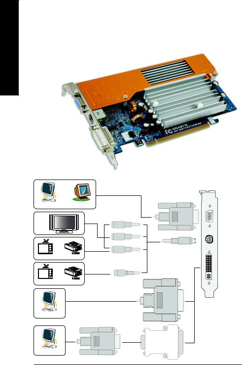
2.1. Board Layout
VGA Monitor Connector
(15-pin)
TV-out
DVI-I Connector
OR |
VGA Output |
|
|
Analog LCD Monitor |
Analog Monitor |
HDTV |
Y |
|
|
|
Pr |
OR |
Pb/AV Output |
|
|
NTSC / PAL TV |
Projector |
|
S-Video Output |
OR |
|
NTSC / PAL TV |
Projector |
|
DVI Output |
Digital LCD Monitor |
|
|
VGA |
|
Output |
Analog LCD Monitor |
|
DVI-I to D-Sub Adapter
VGA Monitor
Connector
(15-pin)
TV-Out
DVI-I Connector
GV-NX71G Series Graphics Accelerator |
- 4 - |
Expansion cards contain very delicate Integrated Circuit (IC) chips. To protect them against damage from static electricity, you should follow some precautions whenever you work on your computer.
1.Turn off your computer and unplug power supply.
2.Use a grounded wrist strap before handling computer components. If you do not have one, touch both of your hands to a safely grounded object or to a metal object, such as the power supply case.
3.Place components on a grounded antistatic pad or on the bag that came with the components whenever the components are separated from the system.
The card contains sensitive electric components, which can be easily damaged by static electricity, so the card should be left in its original packing until it is installed.
Unpacking and installation should be done on a grounded anti-static mat. The operator should be wearing an anti-static wristband, grounded at the same point as the anti-static mat.
Inspect the card carton for obvious damage. Shipping and handling may cause damage to your card. Be sure there are no shipping and handling damages on the card before proceeding.
 DO NOT APPLY POWER TO YOUR SYSTEM IF IT HAS BEEN DAMAGED ON THE CARD.
 In order to ensure your graphics card working correctly, please use official Gigabyte BIOS only. Use none official Gigabyte BIOS might cause problem on the graphics card.
English
- 5 - |
Hardware Installation |
English
2.2. Hardware Installation
Installing Your graphics card.
Now that you have prepared your computer, you are ready to install your graphics accelerator card.
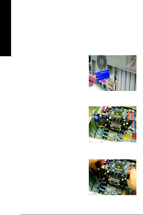
To remove the existing graphics card:
1.Power off the computer and monitor, then disconnect the display cable from the back of your computer.
2.Remove the computer cover. If necessary, consult your computer's manual for help in removing the cover.
3.Remove any existing graphics card from your computer.
Or, if your computer has any on-board graphics capability, you may need to disable it on the motherboard. For more information, please see you computer documentation.
GV-NX71G Series Graphics Accelerator |
- 6 - |
To install your new graphics card:
1.Locate the PCI Express x16 slot. If necessary, remove the metal cover from this slot; then align your graphics card with the PCI Express x16 slot, and press it in firmly until the card is fully seated.
2.Replace the screw to fasten the card in place, and replace the computer cover.
3.Plug the display cable into your card; then turn on the computer and monitor. If your graphics card came with a DVI-I connector, you can connect a flat panel display to the appropriate connector, as shown below...
To VGA Monitor |
To TV / VCR |
To Flat Panel Display |
 To avoid system instability, do not touch the graphics card when it is runnnig.
You are now ready to proceed with the installation of the graphics card driver. Please refer to next chapter for detailed instructions.
English
- 7 - |
Hardware Installation |
English
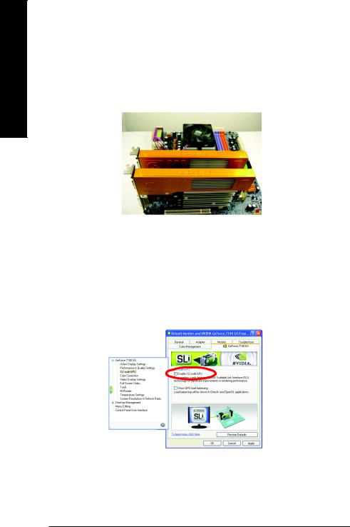
How to enable NVIDIA® SLITM (Scalable Link Interface) technology: (For GV-NX71G512P8-RH / GV-NX71G512P8 only)
After installing two SLI-ready graphics cards of the same model on an SLI motherboard (Figure 1), users can enable SLI mode simply through the graphics card driver (For the GV-NX71G512P8(-RH), driver version must be at least 91.47)(Note).
Figure 1
Step 1: After installing the graphics card driver, right-click on Desktop and select Properties. When Display Properties dialog box appears, select the Settings tab. In Settings, click the Advanced button.
Step 2: Click the GeForce 7100 GS tab when advanced properties dialog box appears. Select SLI multi-GPU from the side menu and select the Enable SLI multi-GPU check box (Figure 2) and click Apply.
Figure 2
Step 3: Restart your system when prompted.
(Note): Only Windows® XP operating system supports SLI mode. Please do not enable SLI multi-GPU in Windows® 2000.
GV-NX71G Series Graphics Accelerator |
- 8 - |
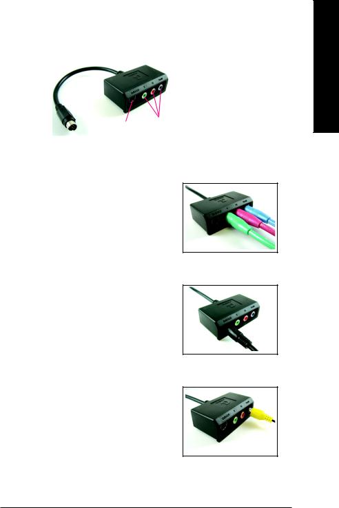
GIGABYTE Video Adapter for Nvidia Graphics Cards
S-Video Out
Connect to the TVOut port on the graphics card.
 AV Out
HDTV Component (Y+Pr+Pb)
(1) Connecting HDTV
Connect your HDTV cables to the video adapter according to the corresponding color.
(Y= Green, Pr= Red, Pb= Blue)
(2) Connecting S-Video
If your TV has a S-Video connection, connect the S- Video cable from your TV to the S-Video Out port on the adapter.
(3) Connecting AV Output
If your TV has Composite video connection, you can connect the RCA cable from your TV to the AV Out port on the adapter.
English
- 9 - |
Hardware Installation |
 Loading...