


MZ32-AR0
AMD EPYC™ 7003 Server Motherboard
User Manual
Rev. 3.0
Copyright
© 2021 GIGA-BYTE TECHNOLOGY CO., LTD. All rights reserved.
The trademarks mentioned in this manual are legally registered to their respective owners.
Disclaimer
Information in this manual is protected by copyright laws and is the property of GIGABYTE. Changes to the specifications and features in this manual may be made by GIGABYTE without prior notice. No part of this manual may be reproduced, copied, translated, transmitted, or published in any form or by any means without GIGABYTE's prior written permission.
Documentation Classifications
In order to assist in the use of this product, GIGABYTE provides the following types of documentation:
User Manual: detailed information & steps about the installation, configuration and use this product (e.g. motherboard, server barebones), covering hardware and BIOS.
User Guide: detailed information about the installation & use of an add-on hardware or software component (e.g. BMC firmware, rail-kit) compatible with this product.
Quick Installation Guide: a short guide with visual diagrams that you can reference easily for installation purposes of this product (e.g. motherboard, server barebones).
Please see the support section of the online product page to check the current availability of these documents
For More Information
For related product specifications, the latest firmware and software, and other information, please visit our website at: http://www.gigabyte.com.
For GIGABYTE distributors and resellers, additional sales & marketing materials are available from our reseller portal: http://reseller.b2b.gigabyte.com
For further technical assistance, please contact your GIGABYTE representative or visit http://esupport.gigabyte.com/ to create a new support ticket.
For any general sales or marketing enquires, you may message GIGABYTE server directly by email: server.grp@gigabyte.com.
Table of Contents
MZ32-AR0 Motherboard Layout....................................................................................... |
5 |
||
Block Diagram.................................................................................................................. |
|
7 |
|
Chapter 1 Hardware Installation...................................................................................... |
9 |
||
1-1 |
Installation Precautions..................................................................................... |
9 |
|
1-2 |
Product Specifications.................................................................................... |
10 |
|
1-3 Installing and Removing the CPU and Heat Sink........................................... |
12 |
||
1-4 Installing and Removing Memory................................................................... |
13 |
||
|
1-4-1 |
8-Channel Memory Configuration .......................................................................... |
13 |
|
1-4-2 |
Installing and Removing the Memory Module ........................................................ |
14 |
|
1-4-3 |
Processor and Memory Module Matrix Table.......................................................... |
14 |
|
1-4-4 |
Memory Population Table ....................................................................................... |
15 |
1-5 Installing and Removing the M.2 SSD Module............................................... |
16 |
||
1-6 Installing and Removing the Mezzanine Card................................................ |
17 |
||
1-7 |
Back Panel Connectors.................................................................................. |
18 |
|
1-8 |
Internal Connectors........................................................................................ |
19 |
|
1-9 |
Jumper Settings.............................................................................................. |
27 |
|
Chapter 2 BIOS Setup................................................................................................... |
28 |
||
2-1 |
The Main Menu............................................................................................... |
30 |
|
2-2 |
Advanced Menu.............................................................................................. |
33 |
|
|
2-2-1 |
Trusted Computing.................................................................................................. |
35 |
|
2-2-2 |
PSP Firmware Versions.......................................................................................... |
36 |
|
2-2-3 |
Legacy Video Select............................................................................................... |
37 |
|
2-2-4 |
AST2500 Super IO Configuration........................................................................... |
38 |
|
2-2-5 |
S5 RTC Wake Settings........................................................................................... |
41 |
|
2-2-6 |
Serial Port Console Redirection.............................................................................. |
42 |
|
2-2-7 |
CPU Configuration.................................................................................................. |
46 |
|
2-2-8 |
PCI Subsystem Settings......................................................................................... |
47 |
|
2-2-9 |
USB Configuration.................................................................................................. |
49 |
|
2-2-10 |
Network Stack Configuration................................................................................... |
51 |
|
2-2-11 |
NVMe Configuration................................................................................................ |
52 |
|
2-2-12 |
SATA Configuration................................................................................................. |
53 |
|
2-2-13 |
UEFI POST LOGO Configuration........................................................................... |
54 |
|
2-2-14 |
AMD Mem Configuration Status.............................................................................. |
55 |
|
2-2-15 |
T1s Auth Configuration............................................................................................ |
56 |
|
2-2-16 |
Intel(R) I350 Gigabit Network Connection............................................................... |
57 |
|
2-2-17 |
VLAN Configuration................................................................................................ |
59 |
|
|
|
|
|
|
- 3 - |
|

|
2-2-18 |
MAC IPv4 Network Configuration........................................................................... |
61 |
|
2-2-19 |
MAC IPv6 Network Configuration........................................................................... |
62 |
2-3 |
AMD CBS Menu............................................................................................. |
64 |
|
|
2-3-1 |
CPU Common Options............................................................................................ |
65 |
|
2-3-2 |
DF Common Options.............................................................................................. |
71 |
|
2-3-3 |
UMC Common Options........................................................................................... |
76 |
|
2-3-4 |
NBIO Common Options.......................................................................................... |
91 |
|
2-3-5 |
FCH Common Options............................................................................................ |
97 |
|
2-3-6 |
NTB Common Options.......................................................................................... |
101 |
|
2-3-7 |
SOC Miscellaneous Control.................................................................................. |
102 |
|
2-3-8 |
Workload Tuning................................................................................................... |
103 |
2-4 |
AMD PBS Menu............................................................................................ |
104 |
|
|
2-4-1 |
RAS....................................................................................................................... |
105 |
2-5 |
Chipset Setup Menu..................................................................................... |
107 |
|
|
2-5-1 |
North Bridge.......................................................................................................... |
108 |
|
2-5-2 |
Fabric Resource.................................................................................................... |
109 |
2-6 |
Server Management Menu........................................................................... |
110 |
|
|
2-6-1 |
System Event Log................................................................................................. |
112 |
|
2-6-2 |
View FRU Information........................................................................................... |
113 |
|
2-6-3 |
BMC Network Configuration.................................................................................. |
114 |
|
2-6-4 |
IPv6 BMC Network Configuration......................................................................... |
115 |
2-7 |
Security Menu............................................................................................... |
116 |
|
|
2-7-1 |
Secure Boot ......................................................................................................... |
117 |
2-8 |
Boot Menu.................................................................................................... |
119 |
|
2-9 Save & Exit Menu......................................................................................... |
121 |
||
2-10 BIOS POST Beep code (AMI standard)....................................................... |
122 |
||
|
2-10-1 |
PEI Beep Codes.................................................................................................... |
122 |
|
2-10-2 |
DXE Beep Codes.................................................................................................. |
122 |
- 4 -

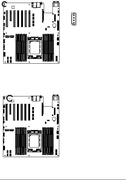
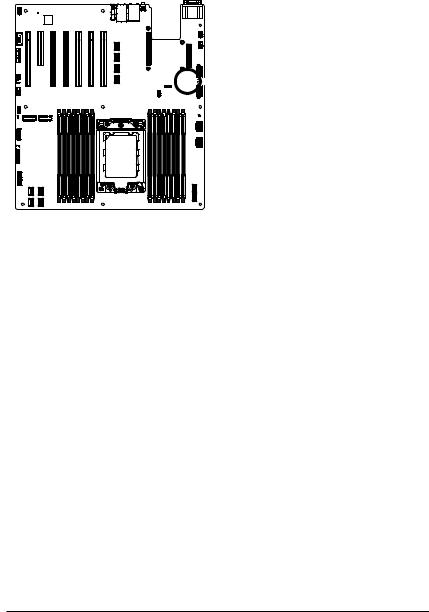
MZ32-AR0 Motherboard Layout
1 |
2 |
3 |
4 |
6 |
43 |
44 |
|
32 |
33 |
34 |
35 |
36 |
31 |
|
|
|
|
30
29
28 
27 
26
25 
24 23
22 
21 |
<![if ! IE]> <![endif]>DIMMP0 H1 DIMMP0 H0 DIMMP0 G1 DIMMP0 G0 DIMMP0 F1 DIMMP0 F0 |
|
|
20 |
|
19 |
16 |
18 |
17 |
37 |
38 |
5 |
42
41
40 |
|
39 |
9 |
| <![if ! IE]> <![endif]>DIMMP0 E1 DIMMP0 E0 |
CPU |
<![if ! IE]> <![endif]>DIMMP0 A0 |
<![if ! IE]> <![endif]>DIMMP0 A1 DIMMP0 B0 DIMMP0 B1 DIMMP0 C0 DIMMP0 C1 DIMMP0 D0 DIMMP0 D1 |
|
|
|
7
8
10
11
12
13
14
15
- 5 -
|
Item |
Code |
Description |
|
|
1 |
R_USB3 |
USB 3.0 Port |
|
|
2 |
LAN1_2 |
GbE Ethernet LAN Port #1/ GbE Ethernet LAN Port #2 |
|
|
3 |
USB3_MLAN |
Server Management LAN Port (Top)/ USB3.0 Ports (Bottom) |
|
|
4 |
SW_ID |
ID button with LED |
|
|
5 |
MEZZ_1A/MEZZ_1B |
OCP Mezzanine Connector |
|
|
6 |
COM1_VGA |
Serial Port (Top)/ VGA Port (Bottom) |
|
|
7 |
SYS_FAN1 |
System Fan Connector #1 |
|
|
8 |
SYS_FAN2 |
System Fan Connector #2 |
|
|
9 |
BAT1 |
Battery Socket |
|
|
10 |
ATX1 |
2 x 12 Pin Main Power Connector |
|
|
11 |
CPU0_FAN |
CPU Fan Connector #0 |
|
|
12 |
P12V_AUX1 |
2 x 4 Pin Power Connector (for CPU) |
|
|
13 |
P12V_AUX2 |
2 x 4 Pin Power Connector (for Memory) |
|
|
14 |
SATA0 |
Slimline SAS 4i Connector (SATAIII 6Gb/s Signal) |
|
|
15 |
SATA1 |
Slimline SAS 4i Connector (SATAIII 6Gb/s Signal) |
|
|
16 |
U2_3 |
Slimline SAS 4i Connector (NVMe/PCIe Gen3 x4) |
|
|
17 |
U2_1 |
Slimline SAS 4i Connector (NVMe/PCIe Gen3 x4) |
|
|
18 |
U2_0 |
Slimline SAS 4i Connector (NVMe/PCIe Gen3 x4) |
|
|
19 |
U2_2 |
Slimline SAS 4i Connector (NVMe/PCIe Gen3 x4) |
|
|
20 |
F_USB3 |
Front Panel USB 3.0 Connector |
|
|
21 |
FP_1 |
Front Panel Header |
|
|
22 |
BP_1 |
HDD Back Plane Board Connector |
|
|
23 |
M2_1 |
M.2 slot (PCIe Gen3 x4, Support NGFF-2242/2260/2280) |
|
|
24 |
M2_2 |
M.2 slot (PCIe Gen3 x4, Support NGFF-2242/2260/2280) |
|
|
25 |
CASE_OPEN |
Case Open Intrusion Alert Header |
|
|
26 |
SYS_FAN5 |
System Fan Connector #5 |
|
|
27 |
F_USB2 |
USB 2.0 Header |
|
|
28 |
SPI_TPM |
TPM Module Connector |
|
|
29 |
SYS_FAN4 |
System Fan Connector #4 |
|
|
30 |
SYS_FAN3 |
System Fan Connector #3 |
|
|
31 |
COM2 |
Serial Port Cable Connector |
|
|
32 |
PCIE_1 |
PCIe x16 Slot (Gen3 x16/x8) |
|
|
33 |
PCIE_2 |
PCIe x8 Slot (Gen3 x0/x8) |
|
|
34 |
PCIE_3 |
PCIe x16 Slot (Gen4 x16) |
|
|
35 |
PCIE_4 |
PCIe x16 Slot (Gen4 x16) |
|
|
36 |
PCIE_5 |
PCIe x16 Slot (Gen4 x8) |
|
|
37 |
PCIE_6 |
PCIe x16 Slot (Gen4 x16) |
|
|
38 |
PCIE_7 |
PCIe x16 Slot (Gen4 x16) switch with 4 x Slim-SAS 4i from 4 x U.2 |
|
|
39 |
SLINK3 |
Slimline SAS 4i Connector |
|
|
40 |
SLINK2 |
Slimline SAS 4i Connector |
|
|
41 |
SLINK1 |
Slimline SAS 4i Connector |
|
|
42 |
SLINK0 |
Slimline SAS 4i Connector |
|
|
43 |
IPMB |
IPMB Connector |
|
|
44 |
LED_BMC |
BMC Firmware Readiness LED |
|
|
|
|
|
|
|
|
|
- 6 - |
|

Block Diagram
- 7 -

This page intentionally left blank
- 8 -

Chapter 1 Hardware Installation
1-1 Installation Precautions
The motherboard contains numerous delicate electronic circuits and components which can become damaged as a result of electrostatic discharge (ESD). Prior to installation, carefully read the user's manual and follow these procedures:
•Prior to installation, do not remove or break motherboard S/N (Serial Number) sticker or warranty sticker provided by your dealer. These stickers are required for warranty validation.
•Always remove the AC power by unplugging the power cord from the power outlet before installing or removing the motherboard or other hardware components.
•When connecting hardware components to the internal connectors on the motherboard, make sure they are connected tightly and securely.
•When handling the motherboard, avoid touching any metal leads or connectors.
•It is best to wear an electrostatic discharge (ESD) wrist strap when handling electronic components such as a motherboard, CPU or memory. If you do not have an ESD wrist strap, keep your hands dry and first touch a metal object to eliminate static electricity.
•Prior to installing the motherboard, please have it on top of an antistatic pad or within an electrostatic shielding container.
•Before unplugging the power supply cable from the motherboard, make sure the power supply has been turned off.
•Before turning on the power, make sure the power supply voltage has been set according to the local voltage standard.
•Before using the product, please verify that all cables and power connectors of your hardware components are connected.
•To prevent damage to the motherboard, do not allow screws to come in contact with the motherboard circuit or its components.
•Make sure there are no leftover screws or metal components placed on the motherboard or within the computer casing.
•Do not place the computer system on an uneven surface.
•Do not place the computer system in a high-temperature environment.
•Turning on the computer power during the installation process can lead to damage to system components as well as physical harm to the user.
•If you are uncertain about any installation steps or have a problem related to the use of the product, please consult a certified computer technician.
- 9 - |
Hardware Installation |
1-2 |
Product Specifications |
||
|
|
|
|
|
|
AMD EPYC™ 7003 series processor family |
|
|
|
Single processor, 7nm, Socket SP3 |
|
|
|
Up to 64-core, 128 threads per processor |
|
|
|
cTDP up to 240W |
|
|
CPU |
|
Fully support 280W |
|
|
||
|
|
NOTE: Please make sure Fan-sink supports over 280W CPU |
|
|
|
Compatible with AMD EPYC™ 7002 series processor family |
|
|
Chipset |
|
System on Chip |
|
|
|
|
|
Memory |
|
16 x DIMM slots |
|
|
DDR4 memory supported only |
|
|
|
8-Channel memory architecture |
|
|
|
RDIMM modules up to 64GB supported |
|
|
|
LRDIMM modules up to 128GB supported |
|
|
|
Memory speed: Up to 3200*/ 2933 MHz |
|
|
|
Note: |
|
|
|
* Follow BIOS setting and memory QVL list if running 3200 Mhz with 2DPC |
|
|
Onboard |
|
Integrated in Aspeed® AST2500 |
|
Graphics |
|
2D Video Graphic Adapter with PCIe bus interface |
|
|
|
1920x1200@60Hz 32bpp |
|
LAN |
|
2 x 1GbE LAN ports (1 x Intel® I350-AM2) |
|
|
1 x 10/100/1000 management LAN |
|
|
Expansion Slots |
|
Slot_7: 1 x PCIe x16 (Gen4 x16 bus) slot; shared with 4 x NVMe ports |
Slot_6: 1 x PCIe x16 (Gen4 x16 bus) slotSlot_5: 1 x PCIe x16 (Gen4 x8 bus) slotSlot_4: 1 x PCIe x16 (Gen4 x16 bus) slotSlot_3: 1 x PCIe x16 (Gen4 x16 bus) slot
Slot_2: 1 x PCIe x8 (Gen3 x0 or x8 bus) slot
Slot_1: 1 x PCIe x16 (Gen3 x16 or x8 bus) slot; shared with slot_2
1 x OCP mezzanine slot with PCIe Gen3 x16 bandwidth (Type1, P1, P2, P3, P4)
2 x M.2 slots: - M-key
- PCIe Gen3 x4
- Supports NGFF-2242/2260/2280 cards
4 x NVMe ports: - SlimSAS 4i type
- PCIe Gen3 x4 per port
- Shared with Slot_7 PCIe Gen4 x16 slot
Hardware Installation |
- 10 - |
Storage Interface |
|
2 x SlimSAS 4i for 8 x SATA ports |
|
|
|
|
|
Internal I/O |
|
1 x 24-pin ATX main power connector |
|
Connectors |
|
2 x 8-pin ATX 12V power connectors |
|
|
|
10 x SlimSAS connectors |
|
|
|
2 x M.2 slots |
|
|
|
1 x CPU fan headers |
|
|
|
5 x System fan headers |
|
|
|
1 x USB 3.0 header |
|
|
|
1 x USB 2.0 header |
|
|
|
1 x COM_2 header |
|
|
|
1 x TPM header |
|
|
|
1 x Front panel header |
|
|
|
1 x HDD back plane board header |
|
|
|
1 x PMBus connector |
|
|
|
1 x IPMB connector |
|
|
|
1 x Clear CMOS jumper |
|
|
|
1 x BIOS recovery jumper |
|
|
|
1 x Buzzer |
|
Rear I/O |
|
3 x USB 3.0 ports |
|
Connectors |
|
1 x VGA port |
|
|
|
1 x Serial port |
|
|
|
2 x RJ45 LAN ports |
|
|
|
1 x MLAN port |
|
|
|
1 x ID button with LED |
|
TPM |
|
1 x TPM header with SPI interface |
|
|
Optional TPM2.0 kit: CTM010 |
||
|
|||
Board |
|
Aspeed® AST2500 management controller |
|
Management |
|
GIGABYTE Management Console (AMI MegaRAC SP-X) web interface |
|
Form Factor |
|
E-ATX |
|
|
305W x 330D (mm) |
||
|
GIGABYTE reserves the right to make any changes to the product specifications and product-related information without prior notice.
- 11 - |
Hardware Installation |

1-3 Installing and Removing the CPU and Heat Sink
Read the following guidelines before you begin to install the CPU:
•Make sure that the motherboard supports the CPU.
•Always turn off the computer and unplug the power cord from the power outlet before installing the CPU to prevent hardware damage.
•Unplug all cables from the power outlets.
•Disconnect all telecommunication cables from their ports.
•Place the system unit on a flat and stable surface.
•Open the system according to the instructions.
WARNING!
Failure to properly turn off the server before you start installing components may cause serious  damage. Do not attempt the procedures described in the following sections unless you are a
qualified service technician.
Follow these instructions to Install the CPU:
1.Loosen the three captive screws in sequential order (1g2g3) securing the CPU cover.
2.Flip open the CPU cover.
3.Remove the CPU cap with CPU from the CPU frame using the handle on the CPU cap.
4.Using the handle on the CPU cap insert the new CPU cap with CPU installed into the CPU frame. Note: Ensure that the CPU is installed in the CPU cap in the correct orientation, with the gold triangle
on the CPU aligned to the top left corner of the CPU cap.
5 Flip the CPU frame with CPU installed into place in the CPU socket.
|
|
|
External cap |
|
|
|
|
1 |
|
|
3 |
CPU |
|
|
|
|
2 |
|
|
4 |
|
||
|
|
|
|
|
|
||
|
|
|
1 |
|
|
|
|
|
|
|
2 |
|
|
|
|
3 |
|
|
|
5 |
|
|
|
|
|
|
7 |
|
4 |
|
1 |
|
|
|
|
|
|
||
|
6 |
|
2 |
2 |
|
3 |
9 |
|
|
|
3 |
|
|
||
|
|
|
|
|
|
||
|
|
|
|
|
|
|
|
|
|
|
1 |
|
|
8 |
|
|
|
|
|
|
|
|
Note:
• |
Lock the CPU by using a T20-Lobe driver to tighten 3 captive nuts in sequence as 1-3. |
|
• |
The screw tightening torque: 16.1 ± 1.2 kgf-cm (14.0 ± 1.0 lbf-in). |
|
|
|
|
Hardware Installation |
- 12 - |
|

1-4 Installing and Removing Memory
Read the following guidelines before you begin to install the memory:
•Make sure that the motherboard supports the memory. It is recommended that memory of the same capacity, brand, speed, and chips be used.
•Always turn off the computer and unplug the power cord from the power outlet before installing the memory to prevent hardware damage.
•Memory modules have a foolproof design. A memory module can be installed in only one direction. If you are unable to insert the memory, switch the direction.
1-4-1 8-Channel Memory Configuration
This motherboard provides 16 DDR4 memory slots and supports 8-Channel Technology. After the memory is installed, the BIOS will automatically detect the specifications and capacity of the memory.
<![endif]>DIMM_P0_H1 DIMM_P0_H0 DIMM_P0_G1 DIMM_P0_G0 DIMM_P0_F1 DIMM_P0_F0 DIMM_P0_E1 DIMM_P0_E0
CPU
<![endif]>DIMM_P0_A0 DIMM_P0_A1 DIMM_P0_B0 DIMM_P0_B1 DIMM_P0_C0 DIMM_P0_C1 DIMM_P0_D0 DIMM_P0_D1
- 13 - |
Hardware Installation |

1-4-2 Installing and Removing the Memory Module
Before installing a memory module, make sure to turn off the computer and unplug the power cord from the power outlet to prevent damage to the memory module.
Be sure to install DDR4 DIMMs on to this motherboard. Follow these instructions to install a DIMM module:
1.Insert the DIMM memory module vertically into the DIMM slot and push it down.
2.Close the plastic clip at both edges of the DIMM slots to lock the DIMM module.
3.Reverse the installation steps when you want to remove the DIMM module.
2

 1
1 
 2
2 


1-4-3 Processor and Memory Module Matrix Table
Processor and Memory Module Matrix Table
|
CPU# |
Channel A/I |
Channel B/J |
Channel C/K |
Channel D/L |
Channel E/M |
Channel F/N |
Channel G/O |
Channel H/P |
|
|||||||||
|
|
|
|
|
|
|
|
|
|
|
|
|
|
|
|
|
|
|
|
|
|
|
|
|
|
|
|
|
8 DIMMs |
|
|
|
|
|
|
|
|
||
|
CPU0 |
|
A1 |
|
B1 |
|
C1 |
|
D1 |
|
E1 |
|
F1 |
|
G1 |
|
H1 |
|
|
|
|
|
|
|
|
|
|
|
|
|
|
|
|
|
|
|
|
|
|
|
|
|
|
|
|
|
|
|
16 DIMMs |
|
|
|
|
|
|
|
|
||
|
CPU0 |
A0 |
A1 |
B0 |
B1 |
C0 |
C1 |
D0 |
D1 |
E0 |
E1 |
F0 |
F1 |
G0 |
G1 |
H0 |
H1 |
|
|
|
|
|
|
|
|
|
|
|
|
|
|
|
|
|
|
|
|
|
|
|
|
|
|
|
|
|
|
|
16 DIMMs |
|
|
|
|
|
|
|
|
||
|
CPU0 |
|
A1 |
|
B1 |
|
C1 |
|
D1 |
|
|
E1 |
|
F1 |
|
G1 |
|
H1 |
|
|
|
|
|
|
|
|
|
|
|
|
|
|
|
|
|
|
|
|
|
|
CPU1 |
|
I1 |
|
J1 |
|
K1 |
|
L1 |
|
|
M1 |
|
N1 |
|
O1 |
|
P1 |
|
|
|
|
|
|
|
|
|
|
|
|
|
|
|
|
|
|
|
|
|
|
|
|
|
|
|
|
|
|
32 DIMMs |
|
|
|
|
|
|
|
|
||
|
CPU0 |
A0 |
A1 |
B0 |
B1 |
C0 |
C1 |
D0 |
D1 |
|
E0 |
E1 |
F0 |
F1 |
G0 |
G1 |
H0 |
H1 |
|
|
|
|
|
|
|
|
|
|
|
|
|
|
|
|
|
|
|
|
|
|
CPU1 |
I0 |
I1 |
J0 |
J1 |
K0 |
K1 |
L0 |
L1 |
|
M0 |
M1 |
N0 |
N1 |
O0 |
O1 |
P0 |
P1 |
|
|
|
|
|
|
|
|
|
|
|
|
|
|
|
|
|
|
|
|
|
Hardware Installation |
- 14 - |

1-4-4 Memory Population Table
EPYC Memory Speed based on DIMM Population (One DIMM per Channel)
DIMM |
DIMM Population |
Max EPYC 7003 |
|
Type |
|
DDR Frequency (MHz) |
|
DIMM 0 |
|||
|
|
|
|
RDIMM |
1R (1 Rank) |
3200 |
|
|
|
||
2R or 2DR (2 Ranks) |
3200 |
||
|
|||
|
|
|
|
|
4DR (4 Ranks) |
3200 |
|
LRDIMM |
|
|
|
2S2R (4 Ranks) |
3200 |
||
|
|
|
|
|
2S4R (8 Ranks) |
3200 |
|
|
|
|
|
3DS |
2S2R (4 Ranks) |
3200 |
|
|
|
||
2S4R (8 Ranks) |
3200 |
||
|
|||
|
|
|
EPYC Memory Speed based on DIMM Population (Two DIMM per Channel)
DIMM |
DIMM Population |
Max EPYC 7003 |
||
Type |
|
|
DDR Frequency (MHz) |
|
DIMM 0 |
DIMM 1 |
|||
|
|
|
|
|
|
-- |
1R |
3200 |
|
|
|
|
|
|
|
1R |
1R |
2933 |
|
|
|
|
|
|
RDIMM |
-- |
2R or 2DR |
3200 |
|
|
|
|
|
|
|
1R |
2R or 2DR |
2933 |
|
|
|
|
|
|
|
2R or 2DR |
2R or 2DR |
2933 |
|
|
|
|
|
|
|
-- |
4DR |
3200 |
|
|
|
|
|
|
|
4DR |
4DR |
2933 |
|
|
|
|
|
|
LRDIMM |
-- |
2S2R (4 Ranks) |
3200 |
|
|
|
|
||
-- |
2S4R (8 Ranks) |
3200 |
||
|
||||
|
|
|
|
|
|
2S2R (4 Ranks) |
2S2R (4 Ranks) |
2933 |
|
|
|
|
|
|
|
2S4R (8 Ranks) |
2S4R (8 Ranks) |
2933 |
|
|
|
|
|
|
|
-- |
2S2R (4 Ranks) |
2933 |
|
|
|
|
|
|
3DS |
2S2R (4 Ranks) |
2S2R (4 Ranks) |
2666 |
|
|
|
|
||
-- |
2S4R (8 Ranks) |
2933 |
||
|
||||
|
|
|
|
|
|
2S4R (8 Ranks) |
2S4R (8 Ranks) |
2666 |
|
|
|
|
|
|
Note:
• When only one DIMM is used, it must be populated in memory slot DIMM1.
- 15 - |
Hardware Installation |
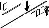
1-5 Installing and Removing the M.2 SSD Module
Follow the steps below to install an optional M.2 SSD module on your motherboard.
Step1. Insert the M.2 SSD module into the slot.
Step2. Secure it with the screw, tightening as necessary to fasten the M.2 SSD module in place.
2
1
Hardware Installation |
- 16 - |

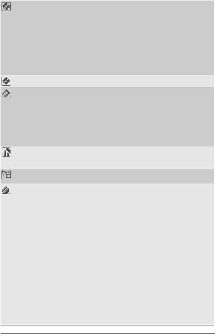
1-6 Installing and Removing the Mezzanine Card
Follow the steps below to install a mezzanine card on your motherboard.
Step1. Insert the mezzanine card into the system ensuring that the connector on the mezzanine card connects to the connector on the motherboard.
Step2. Secure the mezzanine card to the system with three screws.
2
1
1
- 17 - |
Hardware Installation |
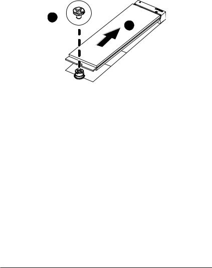
1-7 Back Panel Connectors
u |
x z |
|
w y v {
uSerial Port
Connects to serial-based mouse or data processing devices.
vVGA Port
Connects to a monitor device.
wID button with LED
When the system identification is active, the ID LED on the front/ back panel glows blue.
x10/100/1000 Server Management LAN Port
The LAN port provides Internet connection with data transfer speeds of 10/100/1000Mbps. This port is the dedicated LAN port for Server Management.
yUSB 3.0 Ports
The USB port supports the USB 3.0 specification. Use this port for USB devices such as a USB keyboard/mouse, USB printer, USB flash drive etc.
zRJ-45 LAN Port #1
The Gigabit Ethernet LAN port provides Internet connection at up to 1 Gbps data rate. See the section below for a description of the states of the LAN port LEDs.
{RJ-45 LAN Port #2
The Gigabit Ethernet LAN port provides Internet connection at up to 1 Gbps data rate. See the section below for a description of the states of the LAN port LEDs.
|USB 3.0 Port
The USB port supports the USB 3.0 specification. Use this port for USB devices such as a USB keyboard/mouse, USB printer, USB flash drive etc.
10/100/1000 LAN and ID Button LEDs
Speed LED |
|
|
|
|
|
Link/Activity LED |
10/100/1000 LAN Speed LED: |
|
ID Button/ LED: |
|||||||
|
|
|
|
|
|
|
|
|
|
|
|
State |
Description |
|
State |
Description |
|
|
|
|
|
|
|
|
|
|
|
|
Yellow On |
1 Gbps data rate |
|
Blue On |
System identification is active. |
|
|
|
|
|
|
|
|
|
|
|
|
|
|
|
Off |
System identification is disabled. |
|
|
|
|
|
|
|
|
|
|
|
|
Green On |
100 Mbps data rate |
|||
|
|
|
|
|
|
|
|
|
|
|
|
|
|
|
|
|
|
|
LAN Port |
Off |
10 Mbps data rate |
|
|
|
|||||||||
|
|
|
|
|
|
|
||||||||||
•When removing the cable connected to a back panel connector, first remove the cable from your device and then remove it from the motherboard.
•When removing the cable, pull it straight out from the connector. Do not rock it side to side to
prevent an electrical short inside the cable connector.
Hardware Installation |
- 18 - |

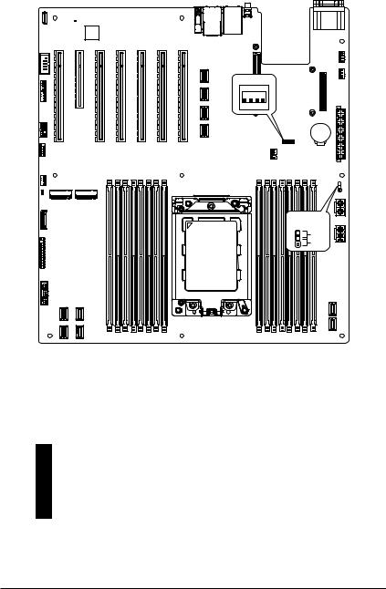
1-8 Internal Connectors
16 |
17 |
|
|
|
|
||
12 |
|
|
|
7 |
|
|
|
8 |
|
|
|
15 |
|
|
|
11 |
|
|
|
9 |
|
|
|
19 |
|
|
|
14 |
<![if ! IE]> <![endif]>DIMMP0 H1 |
<![if ! IE]> <![endif]>DIMMP0 H0 DIMMP0 G1 DIMMP0 G0 DIMMP0 F1 DIMMP0 F0 DIMMP0 E1 DIMMP0 E0 |
|
13 |
|||
|
|
10
CPU
5
6
18 1
 4
4
|
|
|
2 |
| <![if ! IE]> <![endif]>DIMM P0 A0 |
<![if ! IE]> <![endif]>DIMM P0 A1 DIMM P0 B0 DIMM P0 B1 DIMM P0 C0 DIMM P0 C1 DIMM P0 D0 |
<![if ! IE]> <![endif]>DIMM P0 D1 |
3 |
|
1) |
ATX |
11) |
F_USB2 |
2) |
ATX_12V (for CPU) |
12) |
COM2 |
3) |
ATX_12V (for Memory) |
13) |
FP_1 |
4) |
CPU0_FAN |
14) |
BP_1 |
5) |
SYS_FAN1 |
15) |
SPI_TPM |
6) |
SYS_FAN2 |
16) |
IPMB |
7) |
SYS_FAN3 |
17) |
LED_BMC |
8) |
SYS_FAN4 |
18) |
BAT |
9) |
SYS_FAN5 |
19) |
CASE_OPEN |
10) |
F_USB3 |
|
|
Read the following guidelines before connecting external devices:
•First make sure your devices are compliant with the connectors you wish to connect.
•Before installing the devices, be sure to turn off the devices and your computer. Unplug the power cord from the power outlet to prevent damage to the devices.
•After installing the device and before turning on the computer, make sure the device cable has been securely attached to the connector on the motherboard.
- 19 - |
Hardware Installation |
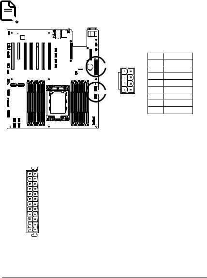
1/2/3) ATX/ATX_12V (2x12 Main Power Connector and 2x4 12V Power Connector)
With the use of the power connector, the power supply can supply enough stable power to all the components on the motherboard. Before connecting the power connector, first make sure the power supply is turned off and all devices are properly installed. The power connector possesses a foolproof design. Connect the power supply cable to the power connector in the correct orientation. The 12V power connector mainly supplies power to the CPU. If the 12V power connector is not connected, the computer will not start.
To meet expansion requirements, it is recommended that a power supply that can withstand high power consumption be used (500W or greater). If a power supply is used that does not provide the  required power, the result can lead to an unstable or unbootable system.
<![endif]>DIMM_P0_H1 DIMM_P0_H0 DIMM_P0_G1 DIMM_P0_G0 DIMM_P0_F1 DIMM_P0_F0 DIMM_P0_E1 DIMM_P0_E0
1 13
12 24
ATX_12V
|
|
|
|
|
|
|
Pin No. |
Definition |
|
|
|
|
ATX |
8 |
4 |
1 |
GND |
|
|
|
|
|
|
2 |
GND |
|
|
|
|
|
|
|
|
||
|
|
|
|
|
|
|
3 |
GND |
|
|
|
|
|
|
|
4 |
GND |
|
|
|
|
ATX_12V |
|
|
5 |
+12V |
|
|
|
|
5 |
1 |
6 |
+12V |
|
|
<![if ! IE]> <![endif]>DIMMP0 A0 |
<![if ! IE]> <![endif]>DIMMP0 A1 DIMMP0 B0 DIMMP0 B1 DIMMP0 C0 DIMMP0 C1 DIMMP0 D0 |
<![if ! IE]> <![endif]>DIMMP0 D1 |
|
||||
CPU |
|
|
|
7 |
+12V |
|||
|
|
|
|
|
|
|||
|
|
|
|
|
|
|
8 |
+12V |
ATX |
|
|
|
|
|
|
|
Pin No. |
Definition |
Pin No. |
Definition |
1 |
3.3V |
13 |
3.3V |
2 |
3.3V |
14 |
-12V |
3 |
GND |
15 |
GND |
4 |
+5V |
16 |
PS_ON |
5 |
GND |
17 |
GND |
6 |
+5V |
18 |
GND |
7 |
GND |
19 |
GND |
8 |
Power Good |
20 |
-5V |
9 |
5VSB |
21 |
+5V |
10 |
+12V |
22 |
+5V |
11 |
+12V |
23 |
+5V |
12 |
3.3V |
24 |
GND |
Hardware Installation |
- 20 - |
4/5/6/7/8/9) CPU0_FAN//SYS_FAN1/SYS_FAN2/SYS_FAN3/SYS_FAN4/SYS_FAN5 (CPU FAN/System FAN Headers)
The motherboard has one 4-pin CPU fan header (CPU_FAN), and two 4-pin (SYS_FAN) system fan headers. Most fan headers possess a foolproof insertion design. When connecting a fan cable, be sure to connect it in the correct orientation (the black connector wire is the ground wire). The motherboard supports CPU fan speed control, which requires the use of a CPU fan with fan speed control design. For optimum heat dissipation, it is recommended that a system fan be installed inside the chassis.
SYS_FAN3
SYS_FAN4
SYS_FAN5
<![if ! IE]><![endif]>DIMM_P0_E0
<![if ! IE]><![endif]>DIMM_P0_E1
<![if ! IE]><![endif]>DIMM_P0_F0
<![if ! IE]><![endif]>DIMM_P0_F1
<![if ! IE]><![endif]>DIMM_P0_G0
<![if ! IE]><![endif]>DIMM_P0_G1
<![if ! IE]><![endif]>DIMM_P0_H0
<![if ! IE]><![endif]>DIMM_P0_H1
CPU
|
|
|
|
1 |
4 |
|
|
|
|
|
SYS_FAN1 |
|
|
|
|
|
|
SYS_FAN2 |
|
|
|
|
|
|
4 |
1 |
|
|
|
CPU0_FAN |
|
|
||
|
|
|
|
Pin No. |
Definition |
|
|
|
|
|
1 |
GND |
|
| <![if ! IE]> <![endif]>DIMMP0 A0 |
<![if ! IE]> <![endif]>DIMMP0 A1 DIMMP0 B0 |
<![if ! IE]> <![endif]>DIMMP0 B1 DIMMP0 C0 DIMMP0 C1 DIMMP0 D0 |
<![if ! IE]> <![endif]>DIMMP0 D1 |
2 |
+12V |
|
3 |
Sense |
|||||
|
|
|
|
|||
|
|
|
|
4 |
Speed Control |
|
•Be sure to connect fan cables to the fan headers to prevent your CPU and system from overheating. Overheating may result in damage to the CPU or the system may hang.
•These fan headers are not configuration jumper blocks. Do not place a jumper cap on the headers.
- 21 - |
Hardware Installation |
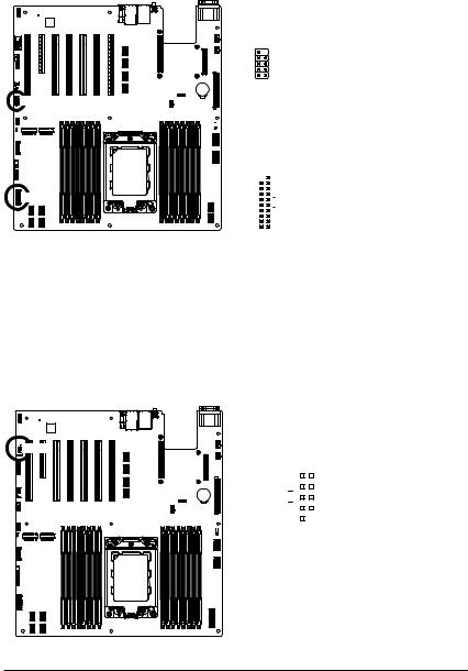
10/11) F_USB3/ F_USB2 (USB 3.0 Connector/ 2.0 Header)
The connector/header conform to USB 2.0/ 3.0 specification. Each USB connector/header can provide two
USB ports via an optional USB bracket. For purchasing the optional USB bracket, please contact the local dealer.
 F_USB2
| <![if ! IE]> <![endif]>DIMMP0 H1 DIMMP0 H0 DIMMP0 G1 DIMMP0 G0 DIMMP0 F1 DIMMP0 F0 DIMMP0 E1 DIMMP0 E0 |
CPU |
<![if ! IE]> <![endif]>DIMMP0 A0 |
<![if ! IE]> <![endif]>DIMMP0 A1 DIMMP0 B0 DIMMP0 B1 DIMMP0 C0 DIMMP0 C1 DIMMP0 D0 DIMMP0 D1 |
|
|
|
F_USB3
USB 2.0 Header |
|
|
|||||
|
|
|
|
|
|
|
|
|
|
|
|
Pin No. |
Definition |
Pin No. |
Definition |
|
|
|
|
|
|
|
|
10 |
9 |
|
1 |
Power (5V) |
6 |
USB DY+ |
|
|
|
|
|
|
|
|
|
|
|
|
|
2 |
Power (5V) |
7 |
GND |
|
|
|
|
|
|
|
|
|
|
|
|
3 |
USB DX- |
8 |
GND |
2 |
1 |
|
|
|
|
|
|
|
4 |
USB DY- |
9 |
No Pin |
|||
|
|
|
|
||||
|
|
|
|
|
|
|
|
|
|
|
|
5 |
USB DX+ |
10 |
No Connect |
|
|
|
|
|
|||
USB 3.0 Connector |
|
|
|||||
|
|
|
|
|
|
|
|
|
|
|
|
Pin No. |
Definition |
Pin No. |
Definition |
|
|
|
|
|
|
|
|
20 1 |
|
1 |
Power |
11 |
IntA_P2_D+ |
||
|
|
|
|
|
|||
|
|
|
|
2 |
IntA_P1_SSRX- |
12 |
IntA_P2_D- |
|
|
|
|
||||
|
|
|
|
|
|
|
|
|
|
|
|
3 |
IntA_P1_SSRX+ |
13 |
GND |
|
|
|
|
|
|
|
|
|
|
|
|
4 |
GND |
14 |
IntA_P2_SSTX+ |
|
|
|
|
||||
|
|
|
|
|
|
|
|
|
|
|
|
5 |
IntA_P1_SSTX- |
15 |
IntA_P2_SSTX- |
|
|
|
|
|
|
|
|
|
|
|
6 |
IntA_P1_SSTX+ |
16 |
GND |
|
|
|
|
|
||||
|
11 10 |
|
|||||
|
|
|
|
7 |
GND |
17 |
IntA_P2_SSRX+ |
|
|
|
|
|
|
|
|
|
|
|
|
8 |
IntA_P1_D- |
18 |
IntA_P2_SSRX- |
|
|
|
|
|
|
|
|
|
|
|
|
9 |
IntA_P1_D+ |
19 |
Power |
|
|
|
|
|
|
|
|
|
|
|
|
10 |
NC |
20 |
No Pin |
12) COM2 (Serial Port Cable Connector)
The COM header can provide one serial port via an optional COM port cable. For purchasing the optional COM port cable, please contact the local dealer.

 COM2
COM2
<![endif]>DIMM_P0_E0
<![if ! IE]><![endif]>DIMM_P0_E1
<![if ! IE]><![endif]>DIMM_P0_F0
<![if ! IE]><![endif]>DIMM_P0_F1
<![if ! IE]><![endif]>DIMM_P0_G0
<![if ! IE]><![endif]>DIMM_P0_G1
<![if ! IE]><![endif]>DIMM_P0_H0
<![if ! IE]><![endif]>DIMM_P0_H1
CPU
<![endif]>DIMM_P0_A0 DIMM_P0_A1 DIMM_P0_B0 DIMM_P0_B1 DIMM_P0_C0 DIMM_P0_C1 DIMM_P0_D0 DIMM_P0_D1
1 |
2 |
|
|
Pin No. |
Definition |
||
|
|
1 |
NDCD- |
||||
|
|
|
|
|
|||
|
|
|
|
|
2 |
NSIN |
|
|
|
|
|
|
3 |
NSOUT |
|
|
|
|
|
|
4 |
NDTR- |
|
|
|
|
|
|
5 |
GND |
|
|
|
|
|
|
6 |
NDSR- |
|
|
|
|
|
|
|
|
|
7 |
NRTS- |
||||||
9 |
10 |
|
|
||||
|
|
|
|
|
8 |
NCTS- |
|
|
|
|
|
|
9 |
NRI- |
|
|
|
|
|
|
10 |
No pin |
|
|
|
|
|
|
|
|
|
Hardware Installation |
- 22 - |
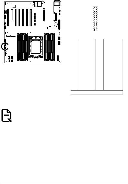
13) FP_1 (Front Panel Header)
Connect the power switch, reset switch, speaker, chassis intrusion switch/sensor and system status indicator on the chassis to this header according to the pin assignments below. Note the positive and negative pins before connecting the cables.
 FP_1
FP_1
<![endif]>DIMM_P0_H1 DIMM_P0_H0 DIMM_P0_G1 DIMM_P0_G0 DIMM_P0_F1 DIMM_P0_F0 DIMM_P0_E1 DIMM_P0_E0
CPU
<![endif]>DIMM_P0_A0 DIMM_P0_A1 DIMM_P0_B0 DIMM_P0_B1 DIMM_P0_C0 DIMM_P0_C1 DIMM_P0_D0 DIMM_P0_D1
1 2
23 24
Pin No. |
Definition |
Pin No. |
Definition |
|
|
|
|
1 |
Power LED+ |
2 |
5V Standby |
|
|
|
|
3 |
No Pin |
4 |
ID LED+ |
|
|
|
|
5 |
Power LED- |
6 |
ID LED- |
|
|
|
|
7* |
HDD LED+ |
8 |
System Status LED+ |
9* |
HDD LED- |
10 |
System Status LED- |
|
|
|
|
11 |
Power Button |
12 |
LAN1 Active LED+ |
|
|
|
|
13 |
GND |
14 |
LAN1 Link LED- |
|
|
|
|
15 |
Reset Button |
16 |
SMBus Data |
|
|
|
|
17 |
GND |
18 |
SMBus Clock |
|
|
|
|
19 |
ID Button |
20 |
Case Open |
|
|
|
|
21 |
GND |
22 |
LAN2 Actve LED+ |
|
|
|
|
23 |
NMI Switch |
24 |
LAN2 Link LED- |
*Note: Pin 7 & Pin 9 are reserved for Gigabyte systems.
The front panel design may differ by chassis. A front panel module mainly consists of power switch, reset switch, power LED, hard drive activity LED, speaker etc. When connecting your chassis front panel module to this header, make sure the wire assignments and the pin assignments are matched  correctly.
- 23 - |
Hardware Installation |
14) BP_1 (HDD Backplane Board Header)
 BP_1
BP_1
<![endif]>DIMM_P0_E0
<![if ! IE]><![endif]>DIMM_P0_E1
<![if ! IE]><![endif]>DIMM_P0_F0
<![if ! IE]><![endif]>DIMM_P0_F1
<![if ! IE]><![endif]>DIMM_P0_G0
<![if ! IE]><![endif]>DIMM_P0_G1
<![if ! IE]><![endif]>DIMM_P0_H0
<![if ! IE]><![endif]>DIMM_P0_H1
CPU
<![endif]>DIMM_P0_A0 DIMM_P0_A1 DIMM_P0_B0 DIMM_P0_B1 DIMM_P0_C0 DIMM_P0_C1 DIMM_P0_D0 DIMM_P0_D1
30 29
|
2 |
1 |
|
|
|
|
|
Pin No. |
Definition |
Pin No. |
Definition |
|
|
|
|
1 |
Reserved |
2 |
BPMI DIN/OUT |
|
|
|
|
3 |
GND |
4 |
BPMI DIN/IN |
|
|
|
|
5 |
BPMI_LOAD |
6 |
GND |
7 |
BPMI_CLK |
8 |
PLD_Program_EN |
|
|
|
|
9 |
GLED_AMB_N |
10 |
GLED_GRN_N |
|
|
|
|
11 |
FAN_IRQ_N |
12 |
Reserved |
13 |
BP_SCL |
14 |
GND |
|
|
|
|
15 |
BP_SDA |
16 |
BP_RST_N |
|
|
|
|
17 |
SMB_U2_TMP_SCL |
18 |
GND |
|
|
|
|
19 |
SMB_U2_TMP_SDA |
20 |
I2C_DEV_RST |
|
|
|
|
21 |
PH_HP_SCL0 |
22 |
GND |
|
|
|
|
23 |
PH_HP_SDA0 |
24 |
GND |
|
|
|
|
25 |
PH_HP_SCL1 |
26 |
GND |
|
|
|
|
27 |
PH_HP_SDA1 |
28 |
GND |
|
|
|
|
15 |
P_3V3_AUX |
30 |
P_3V3_AUX |
|
|
|
|
15) SPI_TPM (Trusted Platform Module Connector)
Trusted Platform Module (TPM) is an international standard for a secure cryptoprocessor, a dedicated microcontroller designed to secure hardware through integrated cryptographic keys.
 TPM
TPM
| <![if ! IE]> <![endif]>DIMMP0 H1 DIMMP0 H0 DIMMP0 G1 DIMMP0 G0 DIMMP0 F1 DIMMP0 F0 DIMMP0 E1 DIMMP0 E0 |
CPU |
<![if ! IE]> <![endif]>DIMMP0 A0 |
<![if ! IE]> <![endif]>DIMMP0 A1 DIMMP0 B0 DIMMP0 B1 DIMMP0 C0 DIMMP0 C1 DIMMP0 D0 DIMMP0 D1 |
|
|
|
|
1 |
2 |
|
|
|
13 14 |
|
|
|
Pin No. Definition |
Pin No. |
Definition |
||
1 |
Clock |
8 |
No Connect |
|
2 |
P_3V3_AUX |
9 |
LPC_LAD2 |
|
3 |
LPC_RST |
10 |
No Pin |
|
4 |
P3V3 |
11 |
LPC_LAD3 |
|
5 |
LPC_LAD0 |
12 |
GND |
|
6 |
IRQ_SERIAL |
13 |
LPC_FRAME_N |
|
7 |
LPC_LAD1 |
14 |
GND |
|
Hardware Installation |
- 24 - |
16) IPMB (Intelligent Platform Management Bus) Connector
The Intelligent Platform Management Bus Communications Protocol defines a byte-level transport for transferring Intelligent Platform Management Interface Specification (IPMI) messages between intelligent I2C devices.
 IPMB
IPMB
|
4 |
Pin No. |
Definition |
|||||||||||
|
|
|
|
|
|
|
|
|
|
|
|
|
||
|
|
|
|
|
|
|
|
|
|
|
|
|
1 |
Clock |
|
|
|
|
|
|
|
|
|
|
|
|
|
|
|
|
|
|
|
|
|
|
|
|
|
|
|
|
2 |
GND |
|
1 |
3 |
Data |
|||||||||||
|
||||||||||||||
|
|
|
||||||||||||
|
4 |
VCC |
||||||||||||
|
|
|
|
|
|
|
|
|
|
|
|
|
||
|
|
|
|
|
|
|
|
|
|
|
|
|
|
|
|
|
|
|
|
|
|
|
|
|
|
|
|
|
|
|
|
|
|
|
|
|
|
|
|
|
|
|
|
|
<![endif]>DIMM_P0_H1 DIMM_P0_H0 DIMM_P0_G1 DIMM_P0_G0 DIMM_P0_F1 DIMM_P0_F0 DIMM_P0_E1 DIMM_P0_E0
CPU
<![endif]>DIMM_P0_A0 DIMM_P0_A1 DIMM_P0_B0 DIMM_P0_B1 DIMM_P0_C0 DIMM_P0_C1 DIMM_P0_D0 DIMM_P0_D1
17) LED_BMC (BMC Firmware Readiness LED)
LED_BMC
<![if ! IE]><![endif]>DIMM_P0_E0
<![if ! IE]><![endif]>DIMM_P0_E1
<![if ! IE]><![endif]>DIMM_P0_F0
<![if ! IE]><![endif]>DIMM_P0_F1
<![if ! IE]><![endif]>DIMM_P0_G0
<![if ! IE]><![endif]>DIMM_P0_G1
<![if ! IE]><![endif]>DIMM_P0_H0
<![if ! IE]><![endif]>DIMM_P0_H1
CPU
State |
Description |
|
|
On |
BMC firmware is initial |
|
|
Blink |
BMC firmware is ready |
|
|
Off |
AC loss |
|
|
<![endif]>DIMM_P0_D1
<![if ! IE]><![endif]>DIMM_P0_D0
<![if ! IE]><![endif]>DIMM_P0_C1
<![if ! IE]><![endif]>DIMM_P0_C0
<![if ! IE]><![endif]>DIMM_P0_B1
<![if ! IE]><![endif]>DIMM_P0_B0
<![if ! IE]><![endif]>DIMM_P0_A1
<![if ! IE]><![endif]>DIMM_P0_A0
- 25 - |
Hardware Installation |
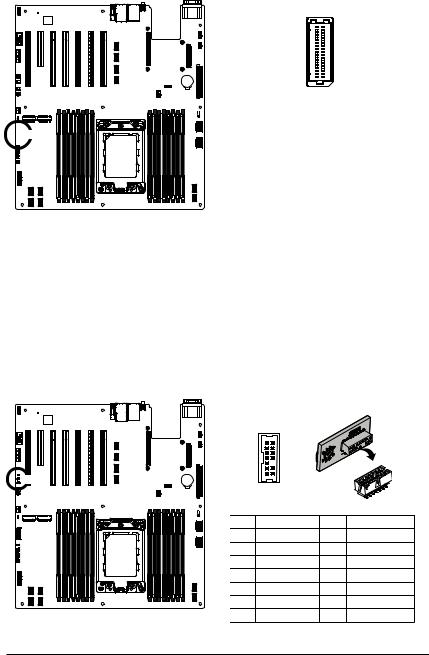
18) BAT (Battery Socket)
The battery provides power to keep the values (such as BIOS configurations, date, and time information) in the CMOS when the computer is turned off. Replace the battery when the battery voltage drops to a low level, or the CMOS values may not be accurate or may be lost.
 BAT
BAT
| <![if ! IE]> <![endif]>DIMMP0 H1 DIMMP0 H0 DIMMP0 G1 DIMMP0 G0 DIMMP0 F1 DIMMP0 F0 DIMMP0 E1 DIMMP0 E0 |
CPU |
<![if ! IE]> <![endif]>DIMMP0 A0 |
<![if ! IE]> <![endif]>DIMMP0 A1 DIMMP0 B0 DIMMP0 B1 DIMMP0 C0 DIMMP0 C1 DIMMP0 D0 DIMMP0 D1 |
|
|
|
2
 1
1
•Always turn off your computer and unplug the power cord before replacing the battery.
•Replace the battery with an equivalent one. Danger of explosion if the battery is replaced with an incorrect model.
•Contact the place of purchase or local dealer if you are not able to replace the battery by yourself or uncertain about the battery model.
•Used batteries must be handled in accordance with local environmental regulations.
19) CASE_OPEN (Case Open Intrusion Alert Header)
This motherboard provides a chassis detection feature that detects if the chassis cover has been removed. This function requires a chassis with chassis intrusion detection design.
 Open: Normal Operation (Default)
 Closed: Active Chassis Intrusion Alert
<![endif]>DIMM_P0_H1 DIMM_P0_H0 DIMM_P0_G1 DIMM_P0_G0 DIMM_P0_F1 DIMM_P0_F0 DIMM_P0_E1 DIMM_P0_E0
CPU
<![endif]>DIMM_P0_A0 DIMM_P0_A1 DIMM_P0_B0 DIMM_P0_B1 DIMM_P0_C0 DIMM_P0_C1 DIMM_P0_D0 DIMM_P0_D1
Hardware Installation |
- 26 - |
1-9 Jumper Settings
- |
21 ',3 |
|
|
Clear CMOS |
|
|
CLR_CMOS |
|
1 |
Default |
|
2 |
Enable |
|
3 |
||
|
Jumper Name |
|
Jumper Setting |
|
||
|
|
|
|
|
|
Clear CMOS |
|
1-2: Normal operation. (Default) |
|
||
|
2-3: Clear CMOS data. |
|
|||
|
|
|
|
||
|
|
|
|
|
|
J2 |
|
|
ON |
|
OFF |
1 |
HSMB_SEL |
|
BIOS Defined |
|
|
2 |
PMBUS_SEL |
|
BIOS Defined |
|
|
3 |
BIOS_PWD |
Clear Supervisor Password |
|
Normal [Default] |
|
4 |
BIOS_RCVR |
|
BIOS Recovery Mode |
|
Normal [Default] |
- 27 - |
Hardware Installation |

Chapter 2 BIOS Setup
BIOS (Basic Input and Output System) records hardware parameters of the system in the EFI on the motherboard. Its major functions include conducting the Power-On Self-Test (POST) during system startup, saving system parameters, loading the operating system etc. The BIOS includes a BIOS Setup program that allows the user to modify basic system configuration settings or to activate certain system features. When the power is turned off, the battery on the motherboard supplies the necessary power to the CMOS to keep the configuration values in the CMOS.
To access the BIOS Setup program, press the <DEL> key during the POST when the power is turned on.
•BIOS flashing is potentially risky, if you do not encounter any problems when using the current BIOS version, it is recommended that you don't flash the BIOS. To flash the BIOS, do it with caution. Inadequate BIOS flashing may result in system malfunction.
•It is recommended that you not alter the default settings (unless you need to) to prevent system instability or other unexpected results. Inadequately altering the settings may result in system's failure to boot. If this occurs, try to clear the CMOS values and reset the board to default values. (Refer to the Exit section in this chapter or introductions of the battery/clearing CMOS jumper in
Chapter 1 for how to clear the CMOS values.)
BIOS Setup Program Function Keys
<f><g> |
Move the selection bar to select the screen |
<h><i> |
Move the selection bar to select an item |
<+> |
Increase the numeric value or make changes |
<-> |
Decrease the numeric value or make changes |
<Enter> |
Execute command or enter the submenu |
<Esc> |
Main Menu: Exit the BIOS Setup program |
|
Submenus: Exit current submenu |
<F1> |
Show descriptions of general help |
<F3> |
Restore the previous BIOS settings for the current submenus |
<F9> |
Load the Optimized BIOS default settings for the current submenus |
<F10> |
Save all the changes and exit the BIOS Setup program |
BIOS Setup |
- 28 - |

Main
This setup page includes all the items of the standard compatible BIOS.
Advanced
This setup page includes all the items of AMI BIOS special enhanced features.
(ex: Auto detect fan and temperature status, automatically configure hard disk parameters.)
AMD CBS
This setup page includes the common items for configuration of AMD motherboard-related information.
AMD PBS Option
This setup page includes the common items for configuration of AMD CPM RAS related settings.
Chipset
This setup page includes all the submenu options for configuring the functions of the North Bridge.
Server Management
Server additional features enabled/disabled setup menus.
Security
Change, set, or disable supervisor and user password. Configuration supervisor password allows you to restrict access to the system and BIOS Setup.
A supervisor password allows you to make changes in BIOS Setup.
A user password only allows you to view the BIOS settings but not to make changes.
Boot
This setup page provides items for configuration of the boot sequence.
Save & Exit
Save all the changes made in the BIOS Setup program to the CMOS and exit BIOS Setup. (Pressing <F10> can also carry out this task.)
Abandon all changes and the previous settings remain in effect. Pressing <Y> to the confirmation message will exit BIOS Setup. (Pressing <Esc> can also carry out this task.)
- 29 - |
BIOS Setup |
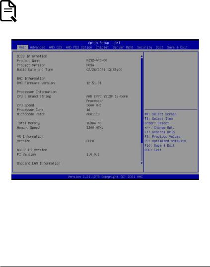
2-1 The Main Menu
Once you enter the BIOS Setup program, the Main Menu (as shown below) appears on the screen. Use arrow keys to move among the items and press <Enter> to accept or enter other sub-menu.
Main Menu Help
The on-screen description of a highlighted setup option is displayed on the bottom line of the Main Menu.
Submenu Help
While in a submenu, press <F1> to display a help screen (General Help) of function keys available for the menu. Press <Esc> to exit the help screen. Help for each item is in the Item Help block on the right side of the submenu.
• When the system is not stable as usual, select the Restore Defaults item to set your system to its defaults.
 • The BIOS Setup menus described in this chapter are for reference only and may differ by BIOS
  version.
BIOS Setup |
- 30 - |
 Loading...