

Page 1
INSTALLATION
INSTRUCTIONS
Decomat 4656Installation instructions
9809
Decomat
4656
Serial no. 701600 -
4997985-02
0301
1
Produced: 1998
Page 2
Contents
Installation instructionsDecomat 4656
Safety rules _______________________________________________ 3
General safety rules _______________________________________ 3
Power cut-off device ______________________________________ 3
Caution symbols _________________________________________ 3
Installation ________________________________________________ 4
Wall-mounted model ______________________________________ 5
Free-standing model ______________________________________ 5
Connection of electricity, water, steam and drain ________________7
Functional check ________________________________________ 10
Technical data ____________________________________________11
Electric circuit diagram ____________________________________12
9809
2
Page 3
Safety rules
This machine is designed with a number of integrated safety devices. To avoid
personal injury it is essential that the safety devices are not bypassed or in any
other way put out of action.
General safety rules
• The machine should be connected according to the instructions.
• The machine may not by used by juveniles.
• Installation work and servicing should be carried out by staff trained to use this
machine.
• The lid lock of the machine may not be bypassed under any circumstances.
• Leakage in the system, eg, due to worn lid gasket, must be repaired
immediately.
• Personnel concerned must study valid handbooks and service manuals prior to
any repairs or service work.
• All plug-in leads must be unplugged from all of the circuit boards of the control
system before any welding on or close to the dishwasher is started.
• The machine may not be sprayed with water.
• Caution must be observed when using corrosive detergents.
• Safety precautions must be observed when using hot water or steam.
Decomat 4656Installation instructions
Power cut-off device
The machine must always be provided with a separate power cut-off device in the
power supply line, easily accessible on the wall.
Caution symbols
This manual contains certain warnings, instructions and advice of such importance
that they are particularly emphasized. The configuration and use of the
appertaining symbols are as follows:
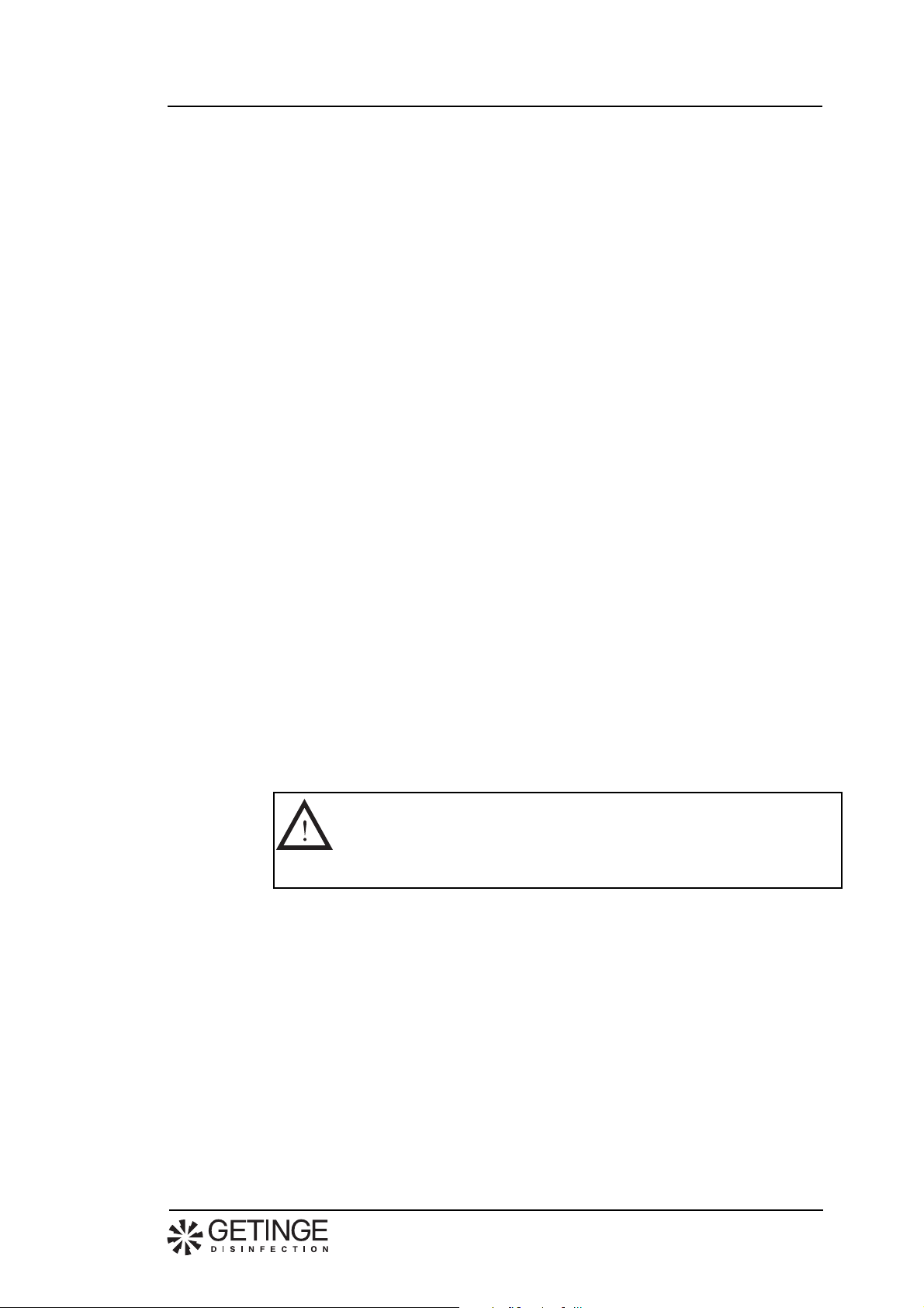
This symbol indicates a warning in the text. It gives warning of
dangers which could lead to minor or major injury to the person
and even to a fatality.
It is also used for warnings to avoid damage to the machine.
9809
3
Page 4
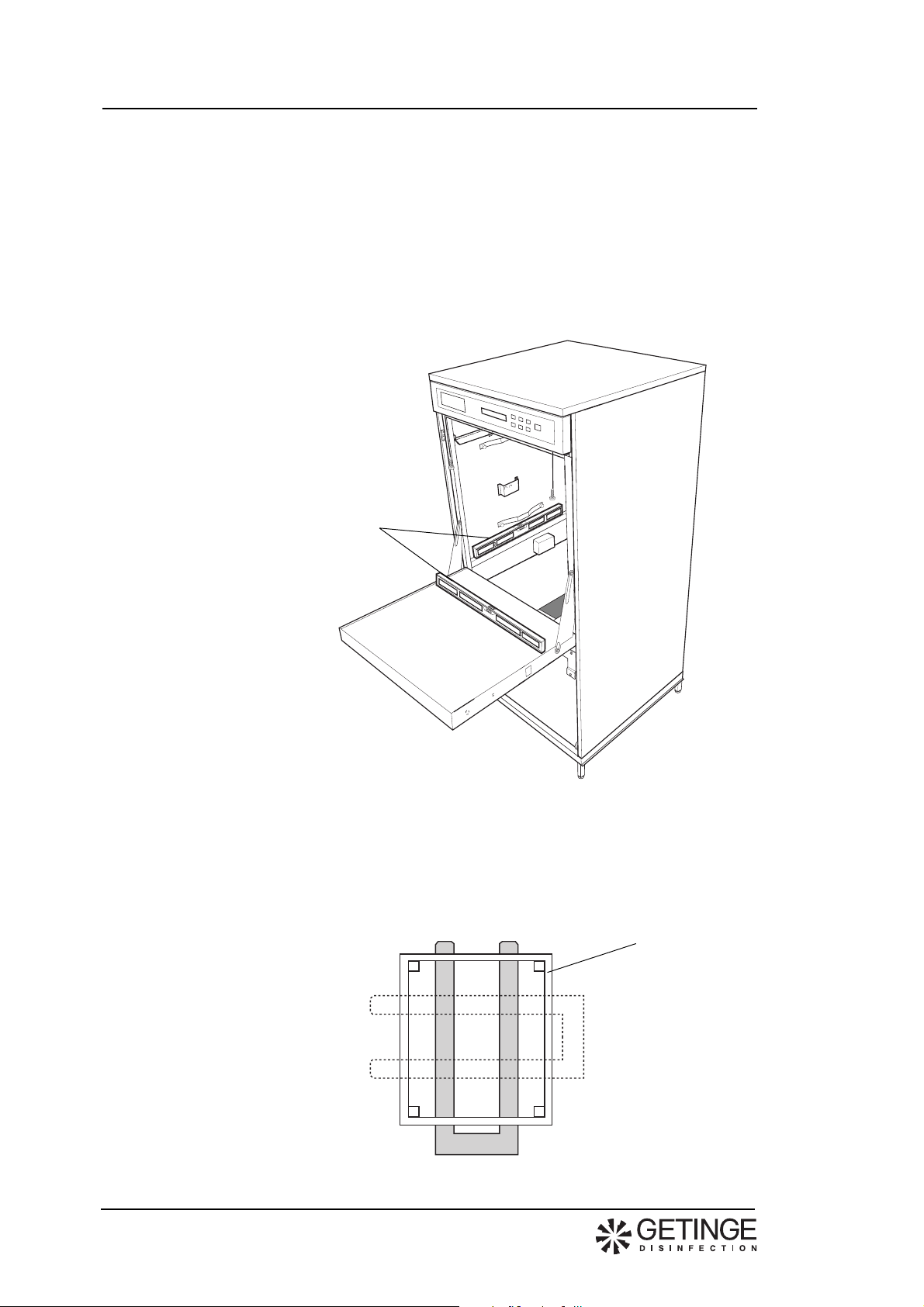
Installation
Adjust the machine with
aid of spirit level
Installation instructionsDecomat 4656
• Pull the machine (standing on a transport pallet) to where it is to stand.
• Remove the detergent compartment.
• Lift the machine from the transport pallet.
• Place the machine in position and set the adjusting screws of the feet to make
the machine stand firm and level. Check with a spirit level as shown in figure
1 to ensure that the machine is level.
• Refit the detergent compartment.
Fig. 1. Adjusting
9809
V222
If the machine is to be moved using a fork-lift truck:
• Position the forks of the truck as illustrated in figure 2 so as not to damage the
machine.
Fig. 2. Positioning the fork-lift forks.
Bottom frame
V318
4
Page 5
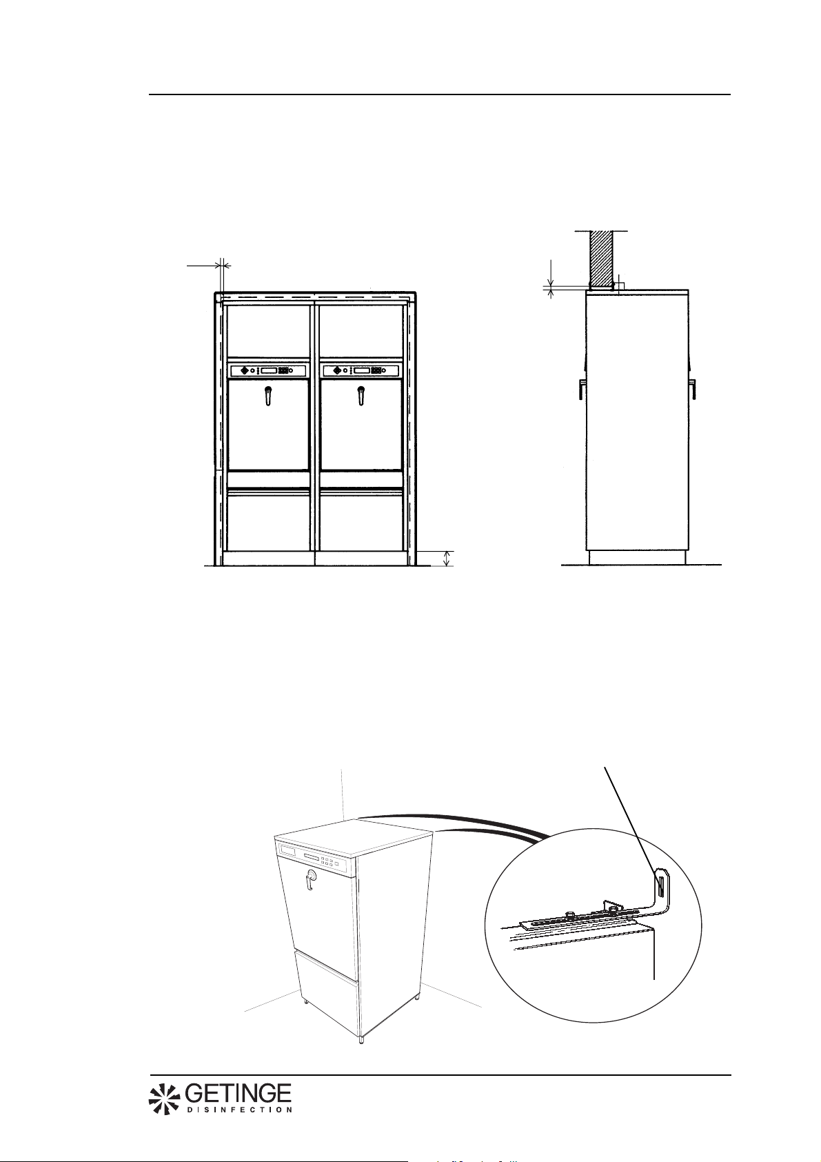
Wall-mounted model
• If the machine is fitted with two doors and is to be installed in a wall, the
clearance between wall and machine must be at least 15 mm.
• If several machines are mounted in-line, they must be adjusted to the same
height when being installed (especially important when a loading trolley is
used).
Decomat 4656Installation instructions
>15 mm
V320
Free-standing model
• Screw off the front panel with the two screws. Lift up and unhook the top
cover.
• Screw the two anti-topple brackets to the wall and tighten the securing screws
to the machine.
• Fit the top cover and front panel.
>15 mm
100 + 5 mm
Fig. 3. Installed in wall
anti-topple bracket
V192
9809
V168
Fig. 4 Anti-topple bracket
5
Page 6

Installation instructionsDecomat 4656
• Check that the door and both side panels are parallel.
If not:
• Remove the lower front panel and adjust the machine.
• Adjust the machine by turning the nuts to the left or right accordingly.
Adjustment must be made on both sides if the machine is fitted with double
doors.
The door and the both side
plates must be parallel
Adjusting screws
9809
6
Page 7

Connection of electricity, water, steam and drain
Installation may be made by authorized personnel only.
• The machine should be fitted with a power cut-off device with a 3 mm gap in
the mains supply feed to facilitate maintenance and servicing.
• Position the disconnecting switch easily accessible on the wall.
• A cable (length 1.5 metres) for connecting to the disconnecting switch
accompanies the machine.
The electric installation in the operating switch located to the left below the
washing chamber of the machine is made as follows:
• The disinfector is connected to protective earth and to the supply voltage
indicated on the data plate.
• Ensure that the correct size of fuse is fitted. The fuse value is stated on the
data plate.
Decomat 4656Installation instructions
Power cut-off
device
9809
V221
Fig. 6. Electrical connection (see electric circuit diagram in the service
instructions)
7
Page 8

Installation instructionsDecomat 4656
• Fit the connections for water, and steam if used, with separate shut-off cocks.
Flush the water and any steam pipes that are to be connected to the machine
so that they are clean and thus prevent clogging of filters and valves.
• Connect the disinfector to the cold and hot water supply, and to steam and
condensate connections if relevant. The connections must be in compliance
with the following requirements:
Connection Pressure Consumption
Cold water 1/2” (15 mm) 100-800 kPa >13 litres per phase
Hot water 1/2” (15 mm) 100-800 kPa >13 litres per phase
Distilled water/Deionized water 3/4" (20 mm) 50-800 kPa* >13 litres per phase
Steam 1/2” (15 mm) 300-500 kPa 0.5 kg/min (300 kPa)
Condensate 1/2” (15 mm)
* A separate supply pump must be used if pressure is below 50 kPa.
• Teflon tape is recommended for the sealing of connections.
Fig. 7. Connection of water, steam and condensate
Distilled/
ionized water
415
345
Hot water
275
90
235
Cold water
Condensate
Steam
Water connections
Front
V195
200
Steam, condensate
100
V196
• Connect the disinfector to a drain that has a capacity of at least 30 litres per
minute. The drain may be connected to the rear or downwards as indicated in
figure 6. Diameter of drain: 50 mm.
9809
8
Page 9

Decomat 4656Installation instructions
• Connect a de-aerator to the dryer (if the machine is fitted with one), diameter:
63 mm.
Fig. 8. Connections for drain and evacuation from dryer
20
Max 1000
200
Adjustable within
this range
100
125
125
250 275
250 275
Front
Adjustable within
this range
50
V196
50
V197
150 - 300
Front
590
230
V198
250
9809
9
Page 10

Functional check
• Ensure that the machine is connected to the correct power supply and that the
• Fill the detergent and rinsing agent bottles and place their level alarms in the
• Place any accessories required in the washing chamber and close the door.
• Choose a program in which dosing is made from each of the detergent and
• Ensure that filling with water in the machine is satisfactory.
• Ensure that the circulation pump is rotating in the right direction as indicated
Installation instructionsDecomat 4656
drain, water, steam and condensate connections are correctly made. Open the
water and steam cocks.
bottles.
rinse-aid bottles and start the machine (see Operating Instructions).
Note.
The circulation pump must be filled with water. The axial seal
may be damaged if there is no water in the pump.
by the arrow on the pump motor. If not, break the power supply, change the
phase sequense and restart the machine.
Fig 9. Circulation pump
9809
10
V171
• Ensure that the dispenser pumps operate at the correct time in accordance
with the description of the program in the Operating Instructions and that
detergent is supplied.
• Check while the program is running that the door/doors cannot be opened.
• On machines with double doors, check the door locking function on
completion of a program as follows:
- Ensure that the door on the soiled side cannot be opened.
- Open the door on the clean side and then close it again.
- Open the door on the soiled side.
- Check that the door on the clean side cannot be opened.
• Ensure that there is no leakage of water or steam. Re-tighten connections for
water, steam and drainage if required.
Page 11

Technical data
Weight: Machine without dryer 145 kg
Width 650 mm
Depth 690 mm
Height: Single machine without dryer1460 mm
Environmental requirements:
Consumption of water 13 l/phase
Cold water
Warm water
Dest./deionized water
pressure is less than 50 kPa)
Steam
Drain dia. 50 mm
Electric power
9809
Max. ambient temperature 50 °C
Noise level 60 dB (A)
Decomat 4656Installation instructions
Machine with dryer 175 kg
Single machine with dryer1860 m m
Double machine 1860 mm
Humidity, maximum 80% at 31 °C
Room temperature 5 - 40 °C
Connections 15 (1/2") mm
Pressure 100-800 kPa
Rate of flow 20 l/min
Temperatur 45-60 °C
Connections 15 (1/2") mm
Pressure 100-800 kPa
Rate of flow 20 l/min
Connections 20 (3/4") mm
Pressure 50-900 kPa (a separate supply pump must be fitted if
Rate of flow 20 l/min
Connections 15 (1/2") mm
Pressure 300-450 kPa
Consumption 0,5 kg/min vid 300 kPa
Variant G2 208-230 V, 3+E, 50/60 Hz (TN)
Fuse 3x25 A
Rated power 9,0 kW
Variant G3 400 V, 3 N+E, 50/60 Hz (TN)
Fuse 3x16 A
Rated power 10,3 kW
Variant V2 without dryer 208-230 V, 3+E, 50/60 Hz (TN)
Fuse 3x10 A
Rated power 1,5 kW
Variant V3 Without dryer 400 V, 3 N+E, 50/60 Hz (TN)
Fuse 3x10 A
Rated power 1,5 kW
Variant V2 with dryer 208-230 V, 3+E, 50/60 Hz (TN)
Fuse 3x16 A
Rated power 4,0 kW
Variant V3 with dryer 400 V, 3 N+E, 50/60 Hz (TN)
Fuse 3x10 A
Rated power 4,0 kW
11
Page 12

Electric power- Japan
Variant G2 200 V, 3+E, 50/60 Hz (TN)
Fuse 3x30 A
Rated power 9,0 kW
Variant V2 without dryer 200 V, 3+E, 50/60 Hz (TN)
Fuse 3x10 A
Rated power 1,5 kW
Variant V2 with dryer 200 V, 3+E, 50/60 Hz (TN)
Fuse 3x16 A
Rated power 4,0 kW
Max. ambient temperature 50 °C
Noise level 60 dB (A)
Installation instructionsDecomat 4656
9809
12
Page 13

Electric circuit diagram
Decomat 4656Installation instructions
9809
13
Page 14

Page 15

Page 16

This product is manufactured by:
GETINGE DISINFECTION AB, Ljungadalsgatan 11, Box 1505, 351 15 Växjö, Sweden
 Loading...