

SERVICE
INSTRUCTIONS
Washer disinfector
Getinge 8666/8668
Mfg. no. SEV0320078-
5015108-00

Safety regulations
Technical data
Description
Software description and
settings
Preventive maintenance
Fault indications and
troubleshooting
Repair and adjustment
5015108-00 2004-03-01
We reserve the right to change without prior notice,
our design and material specifications
Service instruction
Getinge 8666/8668


Safety regulations
1
Service instructions
5015108-00Edition 0403
Safety regulations
CONTENTS
Safety regulations __________________________________________3
General safety regualtions __________________________________ 3
Product libaility __________________________________________ 3
Isolator switch ___________________________________________ 3
Attention symbols ________________________________________ 3

Safety regulations
2
Service instructions
5015108-00 Edition 0403
Safety regulations
3
Service instructions
5015108-00Edition 0403
Safety regulations
This machine is designed with a number of built-in safety devices. To avoid injury, it is highly
important not to bypass or disable these safety devices.
General safety regulations
• Take care when handling the chemical agent used in the machine. Read the details on the
container or contact the manufacturer:
- if agent comes into contact with the operator’s eyes or skin or if the vapours are breathed in, etc.
- about storing the agent and disposing of empty containers.
• The machine must be connected in accordance with the installation instructions.
• Only adults may operate the machine.
• Installation and service work must be done by personnel trained for this machine.
• Never bypass the door switch of the machine.
• Leakage in the system, due to a worn door seal for example, must be dealt with immediately.
• Before repair or service work is done, the personnel concerned must study the relevant
documentation and service manuals.
• Before welding begins on or close to the machine, all wiring connected by plugs and sockets
must be disconnected from all circuit boards in the machine.
• Do not hose down the machine with water.
• Take care when using corrosive detergent .
• Take care with hot water and steam.
• Run a process before starting servicing. If this is not possible, disinfect the machine with
disinfectant before starting servicing.
Product liability
Modifications to the equipment made without the approval of the manufacturer, or incorrect
use, invalidate the manufacturer’s product liability.
Isolating device
The machine must always be fitted with a separate isolating device in the power supply,
mounted in an easily accessible position on the wall.
Attention symbols
Some of the warnings, instructions and advice in this manual are so important that we used the
following special symbols to draw attention to them. The symbols and designs used are:
This symbol indicates a warning in the text of the manual. It warns of a hazard
that may lead to more or less severe injury and in certain cases mortal danger.
It also highlights warnings to avoid damage to equipment.
This symbol highlights a warning in the text of the manual dealing with the
handling of components sensitive to ESD. The hazard that is warns about may
result in damage to hardware and/or circuit boards.


Technical data
1
Service instructions
5015108-00Edition 0403
Technical data
Contents
Technical data______________________________________________3
Alternative connection arrangements ___________________________4

Technical data
2
Service instructions
5015108-00 Edition 0403

Technical data
3
Service instructions
5015108-00Edition 0403
Technical data
Weight incl. water
chamber depth 720 mm 385-525 kg
chamber depth 800 mm 385-525 kg
Width 1110 m m
Depth
chamber depth 720 mm 9 10 mm
chamber depth 800 mm 9 90 mm
Height 1870 m m
Environmental requirements:
Air humidity max 80% at 31 °C
Room temperature 5 - 40 ° C
Water consumption
chamber depth 720 mm ≥ 33 litres/phase
chamber depth 800 mm ≥ 40 litres/phase
Cold water
Connection 20 (3/4") mm
Pressure 100-800 kPa
Flow 30 l/min
Hot water
Temperature 45-60 °C
Connection 20 (3/4") mm
Pressure 100-800 kPa
Flow 30 l/min
Dist./de-ion. water
Connection 20 (3/4") mm
Pressure 100-800 kPa (if the pressure is below 50 kPa a
separate feed pump must be connected)
Flow 30 l/min
Condensate 15 (1/2") mm
Steam
Connection 15 (1/2") mm
Pressure 300-500 kPa
Consumption approx 1.0 kg/min at 300 kPa
Waste ø 50 (2") mm
Capacity 50 l/min
Evacuation air
Air quantity approx 350 m3/h
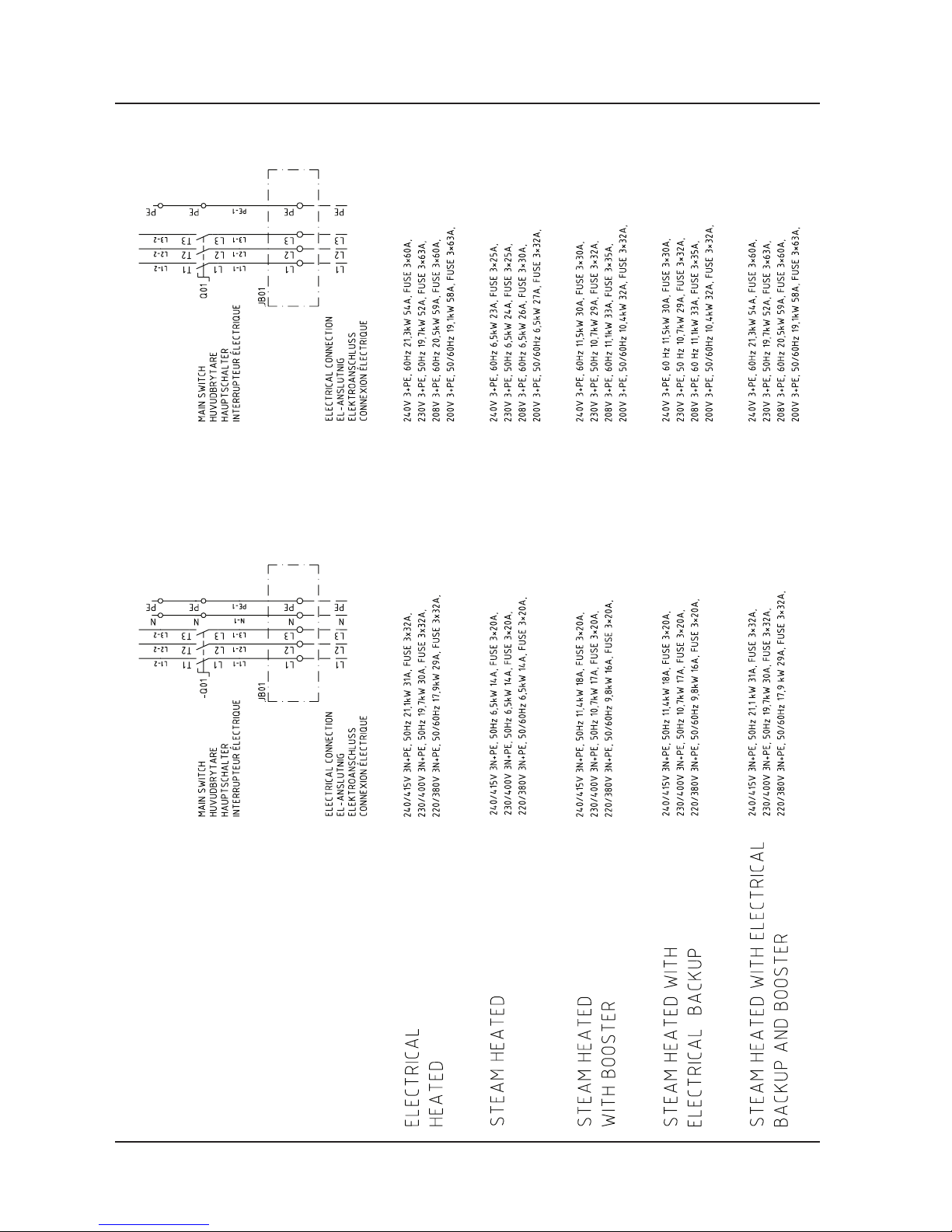
Electrical connection See Alternative connection
arrangements
Compressed air connection 4-8 bar
Max outside temperature 5 0 ° C
Sound level 60 dB (A)
Technical data
4
Service instructions
5015108-00 Edition 0403
Alternative connection arrangements

Description
1
Service instructions
5015108-00Edition 0403
Description
Contents
General ___________________________________________________ 3
Schematic diagram _________________________________________ 4
Electric heating ___________________________________________ 4
Steam heating ____________________________________________ 4
Steam and electric heating __________________________________ 5
Explanation of symbols _____________________________________5
Safe and simple ____________________________________________ 6
Simple service and installation ________________________________ 6
Door operation _____________________________________________ 6
Manually-operated door ____________________________________ 6
Automatically-operated door ________________________________ 7
Dosing system _____________________________________________ 7
Drying ___________________________________________________ 8
Programs _________________________________________________ 9
Abort at start of process ___________________________________ 10
Aborting an ongoing process ______________________________ 10
Fast-stepping a program ___________________________________ 11

Description
3
Service instructions
5015108-00Edition 0403
General
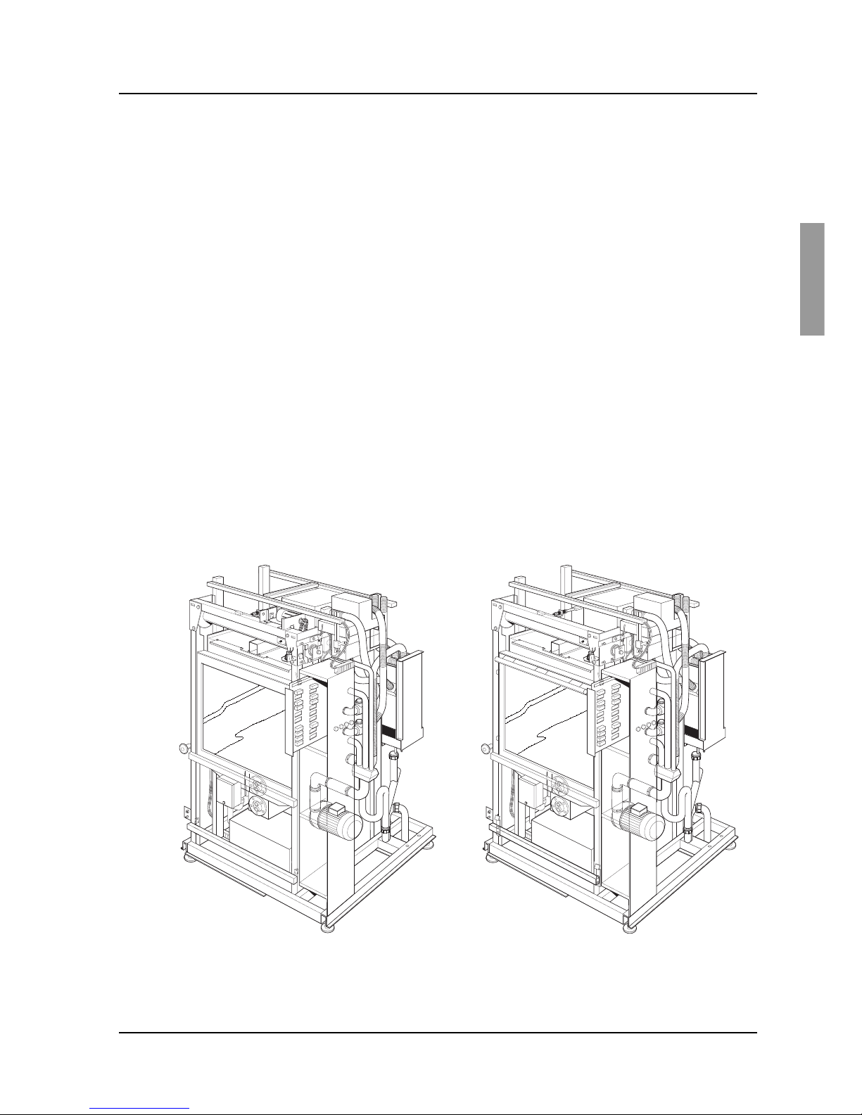
The machine is a fully-automatic washer disinfector for cleaning and disinfecting goods in
hospitals, laboratories and the pharmaceutical industry.
The machine has two washing vanes and two dockings and can be equipped with several
different accessories for different cleaning requirements. These accessories are presented in a
special accessories catalogue.
There are several possible ways of installing and equipping the machine depending on its field
of application:
• Heating by electricity or steam.
• Connection of distilled or de-ionised water.
• Electrically-heated or steam-heated booster tank for the last rinse water.
• Integral drying system.
• Single or double door.
• Extra dosing pump which allows chemical disinfection of heat-sensitive goods.
• Infeeder/outfeeder
• Automatic program selection (basket indication)
• Audible signal on process complete, fault code, etc.
The washer-disinfector has been tested and approved in accordance with SPRI and BGA
recommendations.
V1452
V1297
Washer-disinfector with manual doorWasher-disinfector with automatic door

Description
4
Service instructions
5015108-00 Edition 0403
V1434
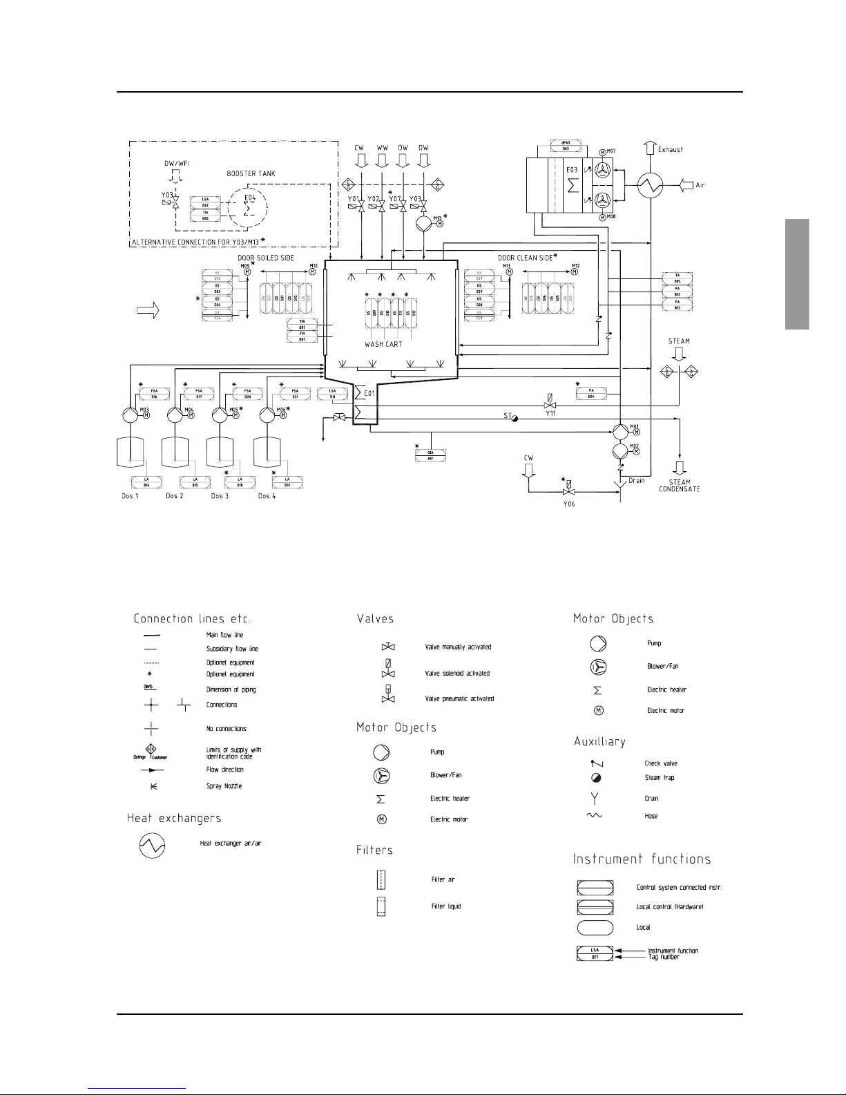
Schematic diagram
Electric heating
Steam heating
V1433
Description
5
Service instructions
5015108-00Edition 0403
Steam and electric heating
Explanation of symbols
V1559
V1560

Description
6
Service instructions
5015108-00 Edition 0403
Safe and simple
The disinfector is controlled by a microprocessor. This has several advantages:
• the built-in service program makes troubleshooting and servicing far easier
• safety and reliability can be kept high by continuous monitoring of the process
• the dosing of detergent, the temperature and the disinfection time can all be altered with
great precision to suit different conditions.
The programs can be adapted precisely to suit the needs of each user. Existing programs can be
re-programmed via a PC. As standard, the washer-disinfector has two to six programs.
The door and wash chamber are well insulated, so that the washer-desinfector is energyefficient and silent in operation.
Operation is simple and the control buttons and few and clearly marked.
Programming may only be done by authorised personnel.
Simple service and installation
Valves and electrical equipment are easily accessible from the front for inspection and service.
Door function
The washer-disinfector can be fitted with a single door or double doors. All doors are of the
vertical sliding type.
The doors can be motorised for automatic opening and closing. The doors have efficient anticrush protection.
Machines with double doors have a system of interlocks to ensure that only one door can be
opened at a time. This means that the clean-side door must be closed and locked by pressing
the W button before the dirty-side door can be opened.
When V is pressed, the door is locked and a yellow lamp flashes (process running) for about
10 seconds. If V is pressed again during this “cancel time”, the dirty-side door is unlocked and
the door can be opened manually or alternatively it opens automatically.
The doors can be locked an unlocked individually from the service program (authorisation required).
Manually-operated door
When the door is closed manually and V is pressed, the door is clocked automatically, the
yellow lamp flashes and the program starts.
When the program is complete, a green lamp lights up on both sides (if there are double doors)
and the clean-side door is unlocked. When the door has been opened manually, the green lamp
goes out. With double doors, the clean-side door must be closed manually and locked by
pressing the W button before the dirty-side door can be unlocked.
A manually-closed door can be opened by pressing the U button for about five seconds. Press
U to unlock the door.
Description
7
Service instructions
5015108-00Edition 0403
Automatically-operated door
WhenVis pressed, the door is locked, the yellow lamp flashes and the program starts.
When the program is complete, a green lamp lights up on both sides (if there are double doors)
and the clean-side door opens automatically. When the door is fully open the green lamp goes
out on both sides. With double doors, the clean-side door must be closed and locked by
pressing the W button before the dirty-side door opens automatically.
An automatically-operated door can be closed on the dirty side without starting a process.
Press and hold U for about five seconds. The door is closed and locked automatically. Press U
to unlock the door.
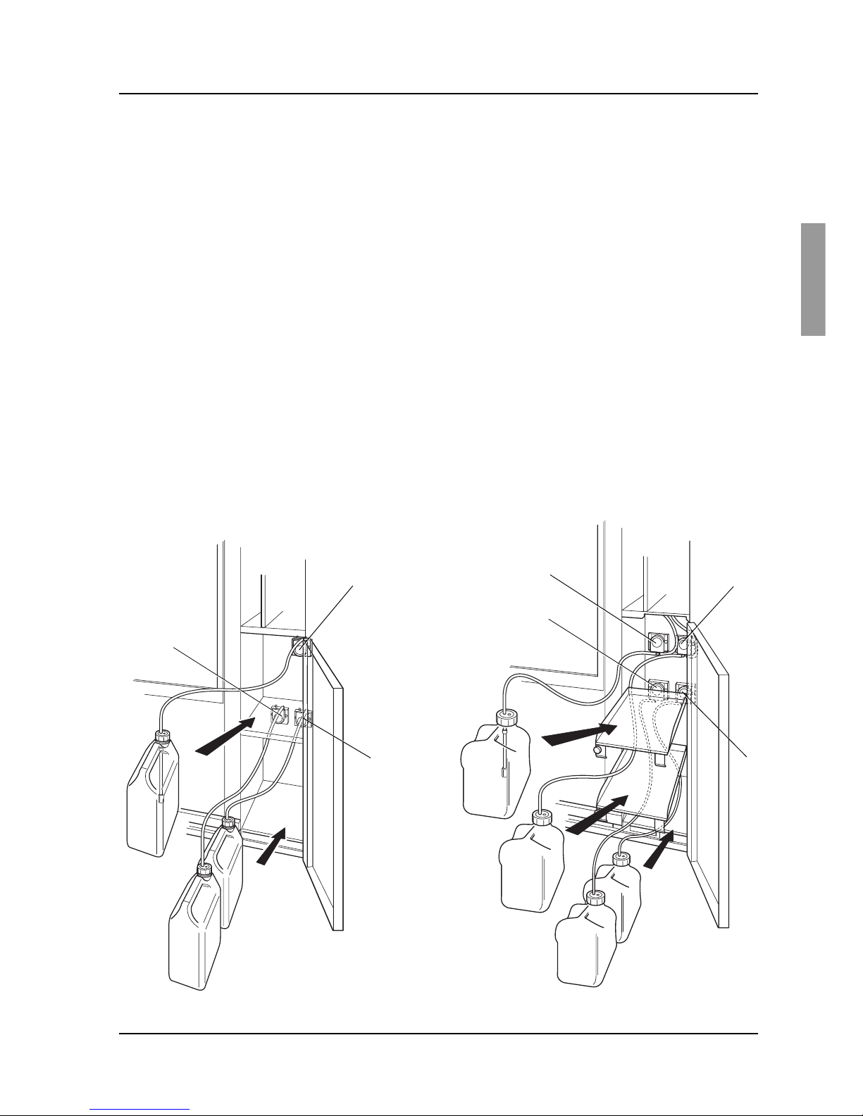
Dosing system
In standard form, the machine has two different dosing systems. One is for alkaline detergent and
one is for rinse-aid or acid detergent. The dosing amount can be set individually for each program.
The machine cannot be started until detergent has been dispensed. If the detergent holder is
empty “DOS 1-4 Low level” appears on the display.
A third and a fourth dosing system for heat-sensitive goods or instrument milk, for example, can
be installed.
Dosing pumps for:
1 Alkaline detergent
2 Rinse-aid or neutralisation
3 Instrument milk or enzyme agent (option)
4 Chemical disinfection (option)
V1313
1
2
4
3
1
2
3
V1576
Chamber depth 720 mm Chamber depth 800 mm
Description
8
Service instructions
5015108-00 Edition 0403
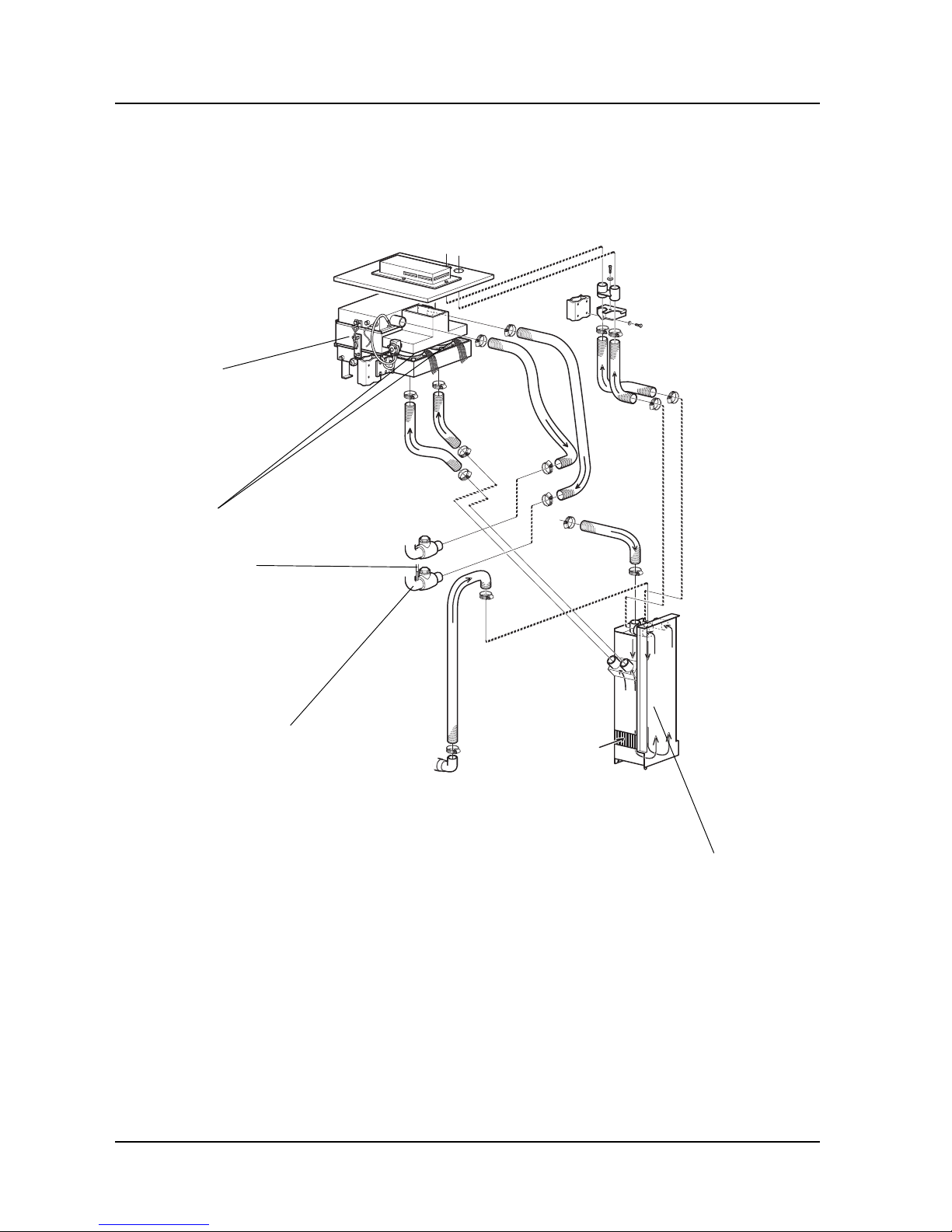
Drying
The machine is equipped with a drying system as standard.
V1293
Heat exchangers
Non-return valve
Filter(s)
Fans
Hose for
connection to
pressure switch
Description
9
Service instructions
5015108-00Edition 0403
Program
The machine has an electronically programmable control system which can hold up to 10-15
programs. Six of these programs can be started with the program selection buttons. With 1-6
you can choose up to six programs. If the control system has more programs, the subsequent
ones are chosen from a scrollable list. You can reach the list of available programs by pressing
S twice, then choosing a program with J or H. Confirm the chosen program with S .
The machine comes with a number of standard programs in the programmer (see the appendix
for Standard programs). Parameters in these programs can be modified to suit the needs of
individual users. Individual programs can be created with a PC. An entire standard program or
parts of one can be used as a starting point for programming.
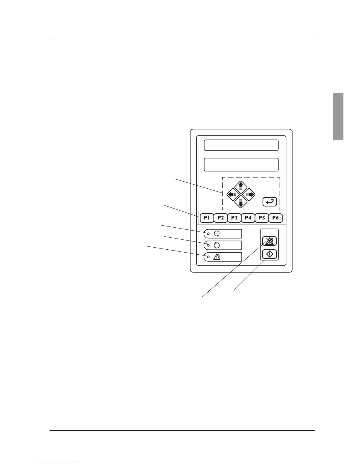
P01 OP-D
60.0C 100
Programming buttons
(see Software description
and settings)
Start wash program
Program selection buttons
V1363
Resets alarm
Green: Process complete
Yellow: Process running
Red: Fault code
Programming may only be done by an authorised service technician.
Programs are chosen with the program selection buttons and the process is started with V (starting
of a process is indicated by the yellow lamp at M flashing for ten seconds and then going out).
When the process is complete, the green lamp at N lights up and the door can be opened
manually (on a machine with manual door). With an automatic door, the door opens
automatically when the process is complete.
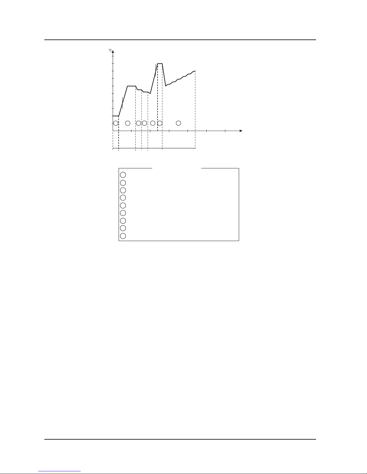
The illustration on the next page shows the program sequence in the OP-D program.
Description
10
Service instructions
5015108-00 Edition 0403
V1513
1 Pre-rinse 1
2 Pre-rinse 2
3 Wash
4 Neutralize
5 Post-rinse 1
6 Post-rinse 2
7 Final rinse
8 Disinfection
9 Drying
Program phases
A Alkaline detergent
B Neutralisation
C Instrument milk (extra
equipment)
If instrument milk is
does, neutralisation is
not dosed.
Abort at start of process
A started program can be aborted within ten seconds of the door locking. To abort a started
process, press V. During the period when the program can be aborted, a yellow lamp flashes at
M. The door is unlocked and opened automatically and the machine can be restarted in the
usual way.
Aborting an ongoing process
During a process, the machine can be stopped with the main switch. If the power is switched on
within 60 seconds, the program continues until the end. If the power is switched on after more
than 60 seconds, error code F00 POWER FAIL is displayed. Press U to silence the alarm
signal. Pressing U again drains liquid from the machine and the dirty side door goes down.
90
80
70
60
50
40
30
20
10
100
10 20 30 40 50 60 min
5
CW HW HW
(DW
option)
A
B
9
3 861
HWCW+HW
7
(C)
Description
11
Service instructions
5015108-00Edition 0403
Fast-stepping a program
All safety functions are disabled for fast stepping.
Fast stepping must only be used during servicing.
Never stop fast stepping in a heating phase. If you do, the machine may
be damaged.
An ongoing program can be fast-stepped phase by phase. Fast stepping can be chosen during
an ongoing process.
1. Fast stepping is chosen in the service program; see tab 5 Software description and setting,
under DIP switches display (1.4.2.4).
2. Set DS02 STEP in STATUS to 1 and press S . Exit the service program.
3. Fast-step with U.
4. Reset DS02 STEP STATUS to 0 and press S . Exit the service program.
Reset DS02 STEP STATUS to 0 after completion of fast stepping.


Software description and settings 1
Service instructions
5015108-00Edition 0403
Contents
Description ________________________________________________ 3
Control panel ______________________________________________ 4
Display _________________________________________________ 4
Program selection buttons __________________________________ 4
Menu tree navigation buttons _______________________________ 5
Scroll in menus and lists _____________________________________ 5
Field editing _______________________________________________ 5
Password _________________________________________________ 6
Operator ________________________________________________6
Parameter ________________________________________________ 6
Supervisor _______________________________________________ 6
Service _________________________________________________ 7
Programming _____________________________________________ 7
Software description and settings
Menu tree ___________________________________________ Appendix


Software description and settings 3
Service instructions
5015108-00Edition 0403
Description
This section describes the PACS 300 control and monitoring system. PACS 300 is an electronic
system that is used to control the various functions of the washer-disinfector. The letters
PACS stand for Programmable Autoclave Control System.
The purpose of the control system is to issue orders and send them to the executive
components of the washer-disinfector so that a number of process steps can be performed in
accordance with a predetermined template. The order signals are worked out by the computer
program of the control unit in conjunction with measurements of actual parameter values for the
current program. These are usually times, temperatures and pressures.
Several different pieces of equipment can be connected to the control unit for programming,
monitoring and documenting the disinfection processes.
The operator communicates with the control unit via a control panel or an ordinary PC.
All operator panels can be used to monitor the processes, since they display all the set
parameter values as well as actual values on request. All relevant data associated with a given
process, such as batch number, operator number, date, etc., can be entered by the operator.
Programs, system definitions and process data can be documented by connecting a printer to
the unit. A host computer can also be connected directly to the CPU of the control system.
When the need arises, a measuring and monitoring system entirely independent of the control
system, can be set up by connecting a PACS SUPERVISOR system, consisting of CPU,
operator panel and connections to the control unit CPU. The measurements of the
SUPERVISOR are made by its own separate temperature and pressure sensors.
The computer contains programs for automatic calibration of the temperature and pressure
sensors. Where alternative correction constants are known, they can be entered manually. The
testing functions include means of activating analog and digital outputs and for monitoring
analog and digital inputs.
Software description and settings4
Service instructions
5015108-00 Edition 0403
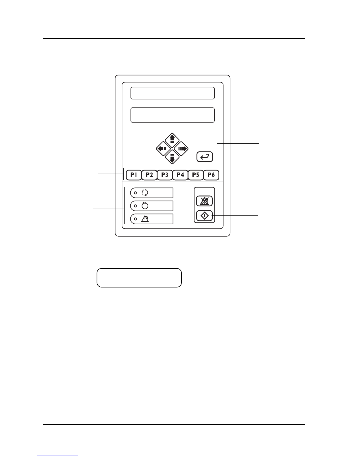
The control panel
The buttons on the control panel are used to choose programs, navigate the menu tree,
acknowledge error codes, etc.
Buttons for
menu tree
navigation
Program selection
buttons
V1363
Acknowledgement
of error
message
Start wash
program
Display
Display
The screen has two lines, each with a capacity 20 characters.
P01 OP-SHORT-D
47.0 °C
Information or error messages appear on the bottom line and replace the text that would
otherwise appear here.
Program selection buttons
With 1-6 you can choose up to six programs. If the control system has more programs, the
subsequent ones are chosen from a scrollable list. You can reach the list of available programs
(from standby mode), by pressing S twice and choosing a program with J or H. Confirm
the chosen program with S .
Indicator lamps

Software description and settings 5
Service instructions
5015108-00Edition 0403
>PRINT LAST CYCLE
SYSTEM V
>SYSTEM ^
ABOUT
SYSTEM ^
>ABOUT
The angle bracket “>” to the left of the top line shows which object will be chosen if you press
S. Bottom right there is a “v” indicating that there are more objects in the list which are
displayed if you press J.
This is what you see if you are in a list. The “arrows” to the right show that there are objects
both above and below the displayed line.
When you reach the end of the object list, only one up-arrow appears at the right edge of the
displayed. Menus and lists are “endless”; you can reach the top of the list by pressing J at
the end of the list.
Buttons for menu tree navigation
The are five buttons for navigating the panel. These fixed buttons are four arrow buttons that
control the cursor (I, K, J and H) and S.
I Used to go back one step (up one level) in menus. If the button is held down for a little
longer, you are returned to the main menu.
K Not used in menus and lists.
J Shows the next object in the list.
H Shows the previous object in the list.
S Goes to the chosen object in the list or opens a field for editing if there is an editable field.
Scroll in menus and lists
You can use I, K, J and H to scroll through menus and lists. You can scroll either line
by line or two lines at a time, depending on what is displayed. The top line of the list may look
like the example below.
Field editing
S opens the chosen field for editing. The content of the field is changed with H or J.
These arrow keys scroll in an endless list containing numbers. When a field is opened for
editing, the first character is highlighted. To move the cursor use I or K.
Entered values are saved when you press S. On saving, the system checks that the value is in
the permitted range.

Software description and settings6
Service instructions
5015108-00 Edition 0403
Passwords
There are five passwords with different levels of authorisation in the system program. The
operator password has the lowest authority; the programming password has full authority.
The following password levels are as follows:
• Operator – code 558387.
• Parameter – contact service for code.
• Supervisor – contact service for code.
• Service – contact service for code.
• Programming – contact service for code.
NOTE: In the menu tree where the password must be entered there is a letter
code (between PW: A-K) which refers to the function for which the relevant
password is authorised.
When a password is entered, the top line shows “ENTER PASSWORD”. Press S to open the
entry field for editing . Each number can be changed with J and H. I and K toggle
between the numbers. Press S to confirm the entered password.
If the wrong password is entered, “WRONG PASSWORD” appears on the first line. Press S to
return to the display showing “ENTER PASSWORD”
NOTE: The password cannot be changed.
Operator
Code in Authority to change
menu tree
A Parameters of type A and to see parameters of type I.
Parameters
Code in Authority to change
menu tree
A Parameters of type A and to see parameters of type I.
H Process-critical configurations, parameters of type P.
Supervisor
Code in Authority to change
menu tree
A Parameters:
B Calendar (time and date)
H Process-critical configurations, parameters of type P.
J Password configuration
K Documentation

Software description and settings 7
Service instructions
5015108-00Edition 0403
Service
Code in Authority to change
menu tree
A Parameters:
B Calendar (time and date)
C Sensor calibration
E Service messages
F DIP switches
G Non-critical system configurations.
H Process-critical configurations, parameters of type P.
J Password configuration
K Documentation
Programming
Code in Authority to change
menu tree
A Parameters:
B Calendar (time and date)
C Sensor calibration
E Service messages
F DIP switches
G Non-critical system configurations.
H Process-critical configurations, parameters of type P.
I Programming (phases and programs)
J Password configuration
K Documentation

Preventive maintenance
1
Service instructions
5015108-00Edition 0403
Preventive maintenance
Contents
General ___________________________________________________ 3
Periodic maintenance _______________________________________ 3
Function check _____________________________________________ 4
Instructions, cable, switch __________________________________ 4
Filter and valves __________________________________________ 4
Controls ________________________________________________ 4
Insert for goods __________________________________________ 4
Door ___________________________________________________ 5
Detergent dosing _________________________________________ 5
Washing system __________________________________________ 5
Temperature control _______________________________________ 5
Dryer ___________________________________________________ 5
Printer (extra equipment) ____________________________________ 5


Preventive maintenance
3
Service instructions
5015108-00Edition 0403
General
The required maintenance interval will depend largely on the quality of the incoming water and
how often the machine is used. The maintenance will have to be determined in each individual
case. We recommend that the stated maintenance operations are done at the specified intervals.
We also recommend that a function check is done once or twice a year.
For repairs or adjustments, see under Repair and adjustment.
Periodic maintenance
This may only be done by authorised personnel.
The machine is connected to the electricity supply and some components are live.
Component Interval
Check Replace if Replace
Replace every
Replace
yearly necessary every year other year 1000 hours
Door seal ••
Hoses between •l
dosing pump and
detergent container
Hose between dosing ••
pump and machine
Filter in incoming ••
media
Overheat protection ••
Hose in hose pump ••
Spray arm wings ••
Sterile filter in dryer ••
Hoses to dryer ••
Non-return valve in dryer ••
Check valve in waste outlet ••
Fan to dryer ••
Ink ribbon for printer ••
Manual door: Spring •
on door closing
Automatic door: Crush •
protection on door closing

Preventive maintenance
4
Service instructions
5015108-00 Edition 0403
Function check
This must only be done by authorised personnel.
The machine is connected to the electricity supply and some components are live.
Instructions, cable, switch
• Check that a goods placing sign has been put up on the wall behind the disinfector.
• Check that the isolator switch on the wall is working and that the connecting cable is
undamaged and free from defects.
Filter and valves
• Check that level switches and manual shutoff valves are working properly.
• Check the filters in the supply line (see under Cleaning the filters in the supply line). Clean
when necessary.
• Check all pipe couplings. Tighten and seal if necessary.
Controls
• The machine is operated with the buttons on the control panel.
• Check that the control buttons are working. If the buttons are working, a beep will be heard.
• While a program is running check that the yellow lamp at M is lit. When the program is
complete, the green lamp at N should light up.
Insert for goods
• Check that the inserts for the machine dock properly with the water outlets.
• Check that washing arms (if fitted) rotate and are not clogged.
• Check that the goods to be cleaned are retained in the insert.
V190
Container alarm

Preventive maintenance
5
Service instructions
5015108-00Edition 0403
Door
Check that the door seal closes tight and is undamaged and that there is no leakage while a
program is running. Clean or replace the seal if necessary.
Detergent dosing
Check that the suction hose and pump are full of detergent or rinse-aid before running a
program. When the pre-programmed amount of detergent is changed, the consumption must be
checked with a measuring glass.
Washing system
All supply lines must be closed when working on the pipe system.
• Check that the washing arms can rotate freely.
• Check that the holes in the washing arms are not blocked. Clean when necessary.
• Check that the coarse strainer in the bottom of the washing chamber is correctly installed.
Clean when necessary.
• Check that all couplings connecting the washing system to the pump and chamber are
leaktight. Tighten and seal if necessary.
Temperature check
• Check the temperature during a program run. Compare time and temperature with the program
sheet. Time and temperature are especially important in the disinfection phase.
The measuring equipment must be capable of registering temperature and time continuously.
High-performance equipment is essential for reliable measuring results, because of the
relatively rapid temperature changes.
Only one measuring point in the centre of the machine is need for the function check.
Note:
Washer-disinfectors that have been shown not to meet the requirements in terms
of temperature, sequence, washing system and safety must not be used until the
faults have been corrected.
Dryer
• Check seals and hoses for leaks once a year.
• Replace the sterile filter if necessary or in the event of an alarm.
Printer (extra equipment)
• Check ink ribbon cartridge
• Check the printout quality.


Fault indications and troubleshooting
1
Service instructions
5015108-00Edition 0403
Fault indications and troubleshooting
Contents
Fault indications ___________________________________________ 3
A red lamp lights up _______________________________________ 3
Messages _______________________________________________ 3
Fault codes ______________________________________________ 4
Acknowledging a fault code _________________________________ 4
Troubleshooting ____________________________________________ 5


Fault indications and troubleshooting
3
Service instructions
5015108-00Edition 0403
Fault indications
Messages appear in plain text on the display. The machine cannot be started until the fault has
been put right. The following messages can be displayed:
Dose 1 low level Empty container alarm 1: if detergent 1 is finished, an operation code is
generated. The alarm is reset automatically when the container is refilled.
Dose 2 low level Empty container alarm 2: if detergent 2 is finished, an operation code is
generated. The alarm is reset automatically when the container is refilled.
Dose 3 low level Empty container alarm 3. If detergent 3 is finished, an operation
code is generated. The alarm is reset automatically when detergent is added.
Dose 4 low level Empty container alarm 4. If detergent 4 is finished, an operation code is generated.
code is generated. The alarm is reset automatically when detergent is added.
Note:
The last process had access to detergent. A message is displayed for future processes.
Red lamp: Disinfection
not achieved
Fault message or
fault code
V1363
P02 OP-D
DOSE 1 LOW LEVEL
P01
Add detergent 1
A red lamp lights up
If the red lamp at O lights up, the process has been aborted because of a fault. Call service
personnel.
Messages

Fault indications and troubleshooting
4
Service instructions
5015108-00 Edition 0403
P02 OP-D
F00 POWER FAIL
Error codes
Fault codes indicate that a serious fault has occurred in the washing process. The fault must be
put right by an authorised service technician.
Acknowledging a fault code
Reset the fault code by:
1. pressing U. The alarm signal is silenced.
2. correcting the fault.
3. The machine is still locked but the current process has been aborted. Pressing U again
drains liquid from the machine and the dirty side door goes down.
Note:
If the draining pump is faulty, the water is not drained from the machine.
NOTE:
The goods in the machine are not clean. Start a new process.

Fault indications and troubleshooting
5
Service instructions
5015108-00Edition 0403
Troubleshooting
The table below describes the fault codes that may be generated and a possible action for each
fault code.
This may only be done by authorised personnel.
The machine is connected to the electricity supply and some components are live.
Fault code Fault Comment
F00 Power failure If the power failure lasts for more than 59 seconds, the process is aborted. The
fault code is generated when the power returns.
F01 The motor cutout has tripped. The motor cutout (–F01) for the circulation pump has tripped.
Possible action:
a. Check that there is power on all phases from the circulation pump.
b. Check that the motor cutout is correctly set (see electrical diagram).
c. Check that the pump impeller rotates easily.
d. Check the direction of rotation (see installation instructions).
F02 Water filling too slow. The water level sensor (-B11) is not activated within ten minutes of filling starting.
Possible action:
a. Check that the shutoff valves are open and that water is reaching the machine.
b. Check that the solenoid valves open and that their filters are not clogged.
F03 Emptying time too long Emptying takes longer than five minutes or the water level sensor (-B11) is still
activated when the emptying phase is complete.
Possible action:
a. Check that the waste pump pumps out water.
b. Check that the pressure switch changes over.
c. Check that the solenoid valve closes (water does not leak in).
F04 Water leakage in the dryer Switch to water level sensors (-B12, -B13) open.
Possible action:
a. Check that the check valves to the dryin connection close.
F05 Fault door, dirty side Door does not lock (-S02) within 10 seconds or opens while a program is running.
Possible action:
a. Check whether the microswitch (-S02) for the “door locked” limit position has
been activated within 10 seconds on door locking.
b. Check that the motor (-M10) and the switch (-S52) for door locking are working.

Fault indications and troubleshooting
6
Service instructions
5015108-00 Edition 0403
Fault code Fault Comment
F06 Fault door, dirty side The door does not unlock (-S01) within 10 seconds.
Possible action:
a. Check whether the microswitch (-S01) for the “door open” limit position has
been activated within 10 seconds on door unlocking.
b. Check that the motor (-M10) and the switch (-S51) for door unlocking are working.
F07 Fault door, dirty side Door does not lock (-S03) within 20 seconds or opens while a program is
running. (Machine with automatic door only.)
Possible action:
a. Check that nothing is trapped in the door.
b. Check whether the microswitch (-S03) for closed door limit position has been
activated for 20 seconds.
c. Check that the motor (-M09) and the switch (-S53) for door locking are working.
d. Check the chain.
F08 Fault door, dirty side The door does not open (-S04) within 20 seconds. (Machine with automatic door only.)
Possible action:
a. Check that nothing is trapped in the door.
b. Check whether the microswitch (-S04) for closed door limit position has been
activated for 20 seconds.
c. Check that the motor (-M09) and the switch (-S54) for door opening are working.
d. Check the chain.
F09 Faulty door, clean side Door does not lock (-S05) within 10 seconds or opens while a program is running.
Possible action:
a. Check whether the microswitch (-S05) for the “door locked” limit position has
been activated within 10 seconds on door locking.
b. Check that the motor (-M12) and the switch (-S55) for door locking are working.
F10 Faulty door, clean side The door does not unlock (-S06) within 10 seconds.
Possible action:
a. Check whether the microswitch (-S06) for the “door open” limit position has
been activated within 10 seconds on door unlocking.
b. Check that the motor (-M12) and the switch (-S56) for door unlocking are working.
F11 Faulty door, clean side Door does not lock (-S07) within 20 seconds or opens while a program is
running. (Machine with automatic door only.)
Possible action:
a. Check that nothing is trapped in the door.
b. Check whether the microswitch (-S07) for closed door limit position has been
activated for 20 seconds.
c. Check that the motor (-M11) and the switch (-S57) for door locking are working.
d. Check the chain.

Fault indications and troubleshooting
7
Service instructions
5015108-00Edition 0403
Fault code Fault Comment
F12 Faulty door, clean side The door does not open (-S08) within 20 seconds. (Machine with automatic door only.)
Possible action:
a. Check that nothing is trapped in the door.
b. Check whether the microswitch (-S08) for closed door limit position has been
activated for 20 seconds.
c. Check that the motor (-M11) and the switch (-S58) for door opening are working.
d. Check the chain.
F15 Flowmeter, dosing 1 Not enough detergent 1 dosed (-B16).
Possible action:
a. Check operation of the dosing pump.
b. Check that there is detergent in the container.
c. Check whether an empty container alarm has occurred.
d. Check that there is no air in the flowmeter and that it is rotating.
e. Check that the hoses are not blocked.
F16 Flowmeter, dosing 2 Not enough detergent 2 dosed (-B17)
Possible action:
a. Check operation of the dosing pump.
b. Check that there is detergent in the container.
c. Check whether an empty container alarm has occurred.
d. Check that there is no air in the flowmeter and that it is rotating.
e. Check that the hoses are not blocked.
F19 Flowmeter, dosing 3 Not enough detergent 3 dosed (-B20)
Possible action:
a. Check operation of the dosing pump.
b. Check that there is detergent in the container.
c. Check whether an empty container alarm has occurred.
d. Check that there is no air in the flowmeter and that it is rotating.
e. Check that the hoses are not blocked.
F20 Flowmeter, dosing 4 Not enough detergent 4 dosed (-B21)
Possible action:
a. Check operation of the dosing pump.
b. Check that there is detergent in the container.
c. Check whether an empty container alarm has occurred.
d. Check that there is no air in the flowmeter and that it is rotating.
e. Check that the hoses are not blocked.

Fault indications and troubleshooting
8
Service instructions
5015108-00 Edition 0403
Fault code Fault Comment
F21 Booster tank slow to fill If filling (-B11) takes longer than 10 minutes, a fault code is generated.
Possible action:
a. Check that the shutoff valves are open and that water is reaching the machine.
b. Check that the solenoid valves open and that their filters are not clogged.
F23 High conductivity The conductivity (-U01) is higher than the set value after the third repeat rinse.
Possible action:
a. Check that the correct type of water is connected.
F24 Low pressure in dryer The differential pressure (-B03) is <150 Pa .
Possible action:
a. Check whether the fan, hoses or filter(s) are faulty.
b. When changing a filter, check that the new filter is correctly installed.
F25 High pressure in dryer The differential pressure (-B03) is > 750 Pa .
Possible action:
a. Check whether the filter is clogged.
F26 Low pressure from circulation pump The pressure (-B04) is <30 kPa.
Possible action:
a. Check the docking between machine and wash rack.
b. Check that the pump impeller rotates easily.
c. Check the direction of rotation (see installation instructions).
d. Check that the detergent is not foaming.
F27 High pressure from circulation pump The pressure (-B04) is > 130 kPa.
Possible action:
a. Check that no nozzles in the washing arms are blocked.
F28 Low temperature in dryer The temperature (-B05) has not risen to 20 degrees C below the set value after
two minutes.
Possible action:
a. Check that there is power on all phases up to the element.
F29 Faulty temperature sensor in booster tank. The temperature (-B06) is <0 °C or >130 °C.
Possible action:
a. Check the temperature sensor (for open-circuit or short-circuit)
F30 Faulty temperature sensor in washing chamber The temperature (-B07) is <0 °C or >130 °C.
Possible action:
a. Check the temperature sensor (for open-circuit or short-circuit)

Fault indications and troubleshooting
9
Service instructions
5015108-00Edition 0403
Fault code Fault Comment
F31 Faulty temperature sensor in washing chamber Independent. The temperature (-B07) is <0 °C or >130 °C.
Possible action:
a. Check the temperature sensor (for open-circuit or short-circuit)
F32 Faulty temperature sensor in dryer The temperature (-B05) is <0 °C or >130 °C.
Possible action:
a. Check the temperature sensor (for open-circuit or short-circuit)
F33 Incorrect temperature in washing chamber Wash temperature (-B07) has not risen by at least 10 degrees C after eight
minutes’ washing.
Possible action for electrically heated machine:
a. Check that there is power on all phases up to the elements.
b. Check the overheat protection of the elements.
Possible action for steam heated machine:
a. Check the steam valve.
b. Check that the ball valve is open and that the filter in the incoming steam is clean.
c. Check steam pressure (see installation instructions).
d. Check condensate drain.
e. Check that there is no back pressure in the condensate drain.
F34 Faulty temperature sensor in washing chamber Wash temperature (-B07) dependent and independent differs by more than ±3
degrees C.
Possible action:
a. Check the calibration of the temperature sensor (see Calibration under
Repair and adjustment)
b. Check the temperature sensor.


Repair and adjustment
1
Service instructions
5015108-00Edition 0403
Repair and adjustment
Contents
Connecting a PC____________________________________________ 3
Connecting a barcode scanner _________________________________ 4
Handscanner ____________________________________________ 4
Barcode scanner _________________________________________ 5
Loading a program to flash memory_____________________________ 6
Loading system programs __________________________________6
Load language files _______________________________________ 8
Cold start ________________________________________________11
Calibration _______________________________________________12
Conductivity meter ______________________________________ 12
Check the output signal from conductivity meter ____________ 1 2
Set the cell constant___________________________________ 12
Calibration __________________________________________ 13
Pressure sensor for circulation pump ________________________ 16
Temperature sensor – with resistor __________________________ 18
Temperature sensors – with ice bath and oil bath _______________ 20
Differential pressure gauge for dryer _________________________ 22
Replacing a temperature sensor ______________________________25
In wash chamber and dryer ________________________________ 25
In booster tank _________________________________________ 25
Door ____________________________________________________26
Position and operation, door switches _______________________ 26
Adjusting door switches __________________________________ 28
Adjusting DOOR UP safety switch __________________________ 29
Replacing the door seal ___________________________________ 30
Removing the door ______________________________________ 31
Adjusting the door closing force____________________________ 32
Adjusting manual door ___________________________________ 33
Overheat protection ________________________________________34
Cleaning the filters in the solenoid valves _______________________35
Dryer____________________________________________________36
Conductivity measurement (extra equipment) ____________________37
Function in washing process_______________________________ 37
Measuring range ________________________________________ 37
Calibration _____________________________________________ 37
Removing a measuring cell ________________________________ 37
Setting detergent and rinse-aid quantities_______________________ 38
Printer (extra equipment)____________________________________39
Replacing the paper roll ___________________________________ 3 9
Ribbon cartridge replacement ______________________________ 4 0
Jumpering an expansion card ________________________________40
Replacing a hose to a hose pump ______________________________42
Booster tank ______________________________________________43
Booster tank with drain tap ________________________________ 43
List of components _________________________________________45

Repair and adjustment
2
Service instructions
5015108-00 Edition 0403

Repair and adjustment
3
Service instructions
5015108-00Edition 0403
V1561
Connecting a PC
An RS-232 cable is needed to connect a PC to the washer-disinfector.
Proceed as follows:
1 . Connect a cable between the PC and port X24 or X25 as shown below.
- X24 is mainly used for a PC and (for example) a scanner.
- X25 is used mainly for T-doc (RS485) and printer (RS232 or RS485).
2 . Set type of communication. The communication settings are done in the service program; see
under tab 5 Software description and settings. Proceed as follows if the PC is:
connected to port X24
- Go into Communication setup COM 0 (1.4.2.3.5.1); see tab 5 Software description and settings.
- Choose COMLI PROTOCOL and press S. Exit the service program.
connected to port X25
- Go into Communication setup COM 1 (1.4.2.3.5.2); see tab 5 Software description and settings.
- Choose COMLI PROTOCOL and press S.
- Go into Communication setup COM 1 (1.4.2.3.5.3); see tab 5 Software description and settings.
- Depending on the distance between the computer and the washer-disinfector, choose
communication speed RS232 (<5 m) or RS485 (>5 m) and press S. Exit the service program.

Repair and adjustment
4
Service instructions
5015108-00 Edition 0403
reset factory defaults
configuration enable (*)
predefined terminal selections - RS-232 - special RS-232 configurations - slave mode (9600, 7, E, 2)
Code 128 / EAN 128 - active
\46\42\46\50\41\4A\01\29\41\5A\60
Code 128 / EAN 128 - EAN 128 identifier - remove ]C1 identifier
Code 93 - active
Code 39 - active (*)
\47\5A\00\41\5E\41\4C\60
RS-232 - preamble / postamble - STX / ETX
RS-232 - hardware/software protocols timeout - compose (ms): 2500
\45\53\3E\02\45\54\3E\03\51\27\04\60
RS-232 - ENQ - not used (*)
temporary configuration mode - update current configuration
\47\3E\00\46\41\02\60
Connecting a barcode scanner
Handscanner
To connect a barcode scanner, proceed as follows.
1. Connect power to the scanner.
2. Calibrate the scanner by scanning in the barcodes below.
Scan in the top barcode. Wait for a beep, then scan in the
next code. Continue until all codes have been scanned in.
3. Connect a communication cable between the scanner and
port X24.
4 . Set type of communication. The communication settings are done in the service program; see
under tab 5 Software description and settings.
- Go into Communication setup COM 0 (1.4.2.3.5.1); see tab 5 Software description and settings.
- Choose Scanner and press S. Exit the service program.

Repair and adjustment
5
Service instructions
5015108-00Edition 0403
Barcode scanner
To connect a barcode scanner, proceed as follows.
1. Connect power to the scanner.
2 . Connect a communication cable between the scanner
and port X24.
3 . Set type of communication. The communication
settings are done in the service program; see under
tab 5 Software description and settings.
- Go into Communication setup COM 0 (1.4.2.3.5.1);
see tab 5 Software description and settings.
- Choose Scanner and press S. Exit the service
program.
Barcode
scanner

Repair and adjustment
6
Service instructions
5015108-00 Edition 0403
Loading a program to flash memory
The flash memory can be loaded with new wash programs or new system programs. Loading
new wash programs requires the CS-1000 program, which can be purchased from Getinge.
Instructions are supplied with CS-1000. System programs and language versions are loaded
with Flashloader.
Loading system programs
Note:
Always make a backup copy before starting work on updating system programs.
1 . Connect a PC to the machine; see under Connecting a PC.
2 . Check that the machine is in STANDBY mode.
3 . Make a backup copy by starting CS 1000 and choosing Tools/PACS RAM/Upload To File...
4 . Save the *.prm file in your chosen location.
The program will report an error during conversion. Disregard this. To check that conversion
was successful, check the size of the *.prm file. The size of the file should be 84416 bytes.
5 . Switch off the power to the machine with the main switch.
6 . Change the jumper (X29) on the board for the PACS 300 control system from Normal to Test.
Flash
Prom
X28
X29
TEST
Norma
X30
ON OFF
V1544
V1577

Repair and adjustment
7
Service instructions
5015108-00Edition 0403
7 . Switch on the power to the machine with the main switch. The display should now show:
GETINGE
Ram OK
or
GETINGE PACS 300
Version X.XX (XXXX)
8 . Start Flashloader from PC.
9. Set up as shown.
File name Choose the right program file (*.a37).
Com port The port to which you connected the data cable to your PC.
Baud rate Choose 57600
All Sectors and Verbose must be checked (=selected).
10. Start loading by pressing Program !. The following image appears.
V1578
V1579

Repair and adjustment
8
Service instructions
5015108-00 Edition 0403
11. When loading is complete, the following image appears. Press OK.
12. Now the display shows:
SW Update 0x2497
Updating CRC....
A beep is heard and the display shows:
SW Update 0x2497
CRC OK
13. Check that the battery jumper (X30) is set to ON.
14. Switch off the power to the machine with the main switch.
15 . Change the jumper (X29) to Normal.
16. Switch on the power to the machine with the main switch. The display should now show:
P00
17 . Close Flashloader.
18 . Start CS-1000 and load wash programs; see instructions for CS-1000.
Load language files
Note:
Always make a backup copy before starting work on updating system programs.
1 . Connect a PC to the machine; see under Connecting a PC.
2 . Check that the machine is in STANDBY mode.
3 . Make a backup copy by starting CS 1000 and choosing Tools/PACS RAM/Upload To File...
4 . Save the *.prm file in your chosen location.
The program will report an error during conversion. Disregard this. To check that
conversion was successful, check the size of the *.prm file. The size of the file should be
84416 bytes.
5 . Switch off the power to the machine with the main switch.
V1580
V1577

Repair and adjustment
9
Service instructions
5015108-00Edition 0403
6 . Change the jumper (X29) on the board for the PACS 300 control system from Normal to Test.
Flash
Prom
X28
X29
TEST
Norma
X30
ON OFF
V1544
7. Set up as shown.
File name Choose the right program file (*.a37).
Com Port The port to which you connected the data cable to your PC.
Baudrate Choose 57600
All Sectors and Verbose must be checked (=selected).
V1578

Repair and adjustment
10
Service instructions
5015108-00 Edition 0403
8. Choose the Language tab.
9 . Choose the relevant files:
- Language support file,
- Language file for PACS database.
10. Set Flash Sector for Language to 8 and 10 (as shown).
11 . Check (select) Transfer.
11 . Click Transfer->. The language files are now transferred to PACS 300.
12 . Close Flashloader.
V1581

Repair and adjustment
11
Service instructions
5015108-00Edition 0403
Flash
Prom
X28
X29
TEST
Norma
X30
ON OFF
V1544
Cold start
Do a cold start when the machine has hung and you cannot proceed with the program.
1 Switch off the power to the machine.
2 Move the battery jumper (X30) to Off.
3 Move the programming jumper (X29) from Normal to Cold.
4 Switch on the power.
5 Wait until CRC OK appears on the display.
6 Move the battery jumper (X30 back to On. Note: The power is still on.
7 Switch off the power.
8 Move the programming jumper (X29) from Cold to Normal.
9 Switch on the power.
10 Set the doors to the home position using the service program (tab 5 Software description
and settings, Test digital output display (1.4.2.5.3.4)) or CS1000.
Home position for the doors:
Dirty side = door unlocked and open
Clean side = door closed and locked

Repair and adjustment
12
Service instructions
5015108-00 Edition 0403
Calibration
Conductivity meter
Check the output signal from conductivity meter
To check the output signal, proceed as follows.
1. Press [ on the conductivity meter.
2 . Enter code 22 with Y and Z.
3. Press [. Setup 1 appears.
4 . Choose with Y and Z Output.
5. Press [. Sel. Type appears.
6. Choose LIN with Y and Z.
7. Press [.
8 . Choose 4-20 mA with Y and Z.
9. Press [ .
10 .Set with Y and Z so that 4 mA =0.000 µS/cm.
11 .Press [.
12 .Set with Y and Z so that 20 mA = 200 µS/cm.
13 .Press [.
14.Press Y and Z at the same time to log out.
Set the cell constant
To set the cell constant, proceed as follows:
1. Press [ .
2 . Enter code 22 with Y and Z.
3. Press [. Setup 1 appears.
4. Press [ until the display shows Cellconst.
5. With Y and Z, set the relevant cell constant; see the calibration certificate.
6. Press [ .
7. Press Y and Z at the same time to log out.

Repair and adjustment
13
Service instructions
5015108-00Edition 0403
Calibration
To calibrate the conductivity meter, proceed as follows.
1 . Connect a PC with the CS 1000 program installed to the disinfector.
2. Press [ on the conductivity meter.
3 . Enter code 22 with Y and Z.
4. Press [. Setup 1 appears.
5 . Choose Output with Y and Z .
6. Press [. Sel. Type appears.
7 . Choose SIM with Y and Z.
8. Press [.
9 . Choose to 0 …22 mA with Y och Z.
10 . Set 4 mA.
11 . Press [.
12. Start CS 1000 and choose Settings/Calibration/Analog Input Automatic...
V1563

Repair and adjustment
14
Service instructions
5015108-00 Edition 0403
13 .Click Conductivity (A) and then Calibrate (B).
A
B
A
14 .Enter the value 0 (A) and click Set Low.
V1564
V1565

Repair and adjustment
15
Service instructions
5015108-00Edition 0403
15. Set 20 mA on the conductivity meter with Y and Z.
16 . Enter 200 (A) in CS 1000 and click Set High.
17. Check that the value (B) rises to 200.
18 . Log off CS 1000.
19 . Choose Output with Y and Z.
20. Press [. Sel. Type appears.
21 . Choose LIN with Y and Z.
22 . Press [.
23. Press Y and Z together several times until you are logged out of the conductivity meter.
A
B
V1566

Repair and adjustment
16
Service instructions
5015108-00 Edition 0403
A
B
Pressure sensor for circulation pump
To calibrate the pressure sensor for the circulation pump, proceed as follows.
1. Connect a PC with the CS 1000 program installed to the disinfector.
2 . Connect a process simulator to A01-X2;
+ to 2
- to 5.
3 . Set the process simulator to 4 mA.
4 . Start CS 1000 and choose Settings/Calibration/Analog Input Automatic...
5 . Click Pump pressure (A) and then Calibrate (B).
V1563
V1567

Repair and adjustment
17
Service instructions
5015108-00Edition 0403
6 . Enter the value 0 (A) and click Set Low.
7 . Set the process simulator to 20 mA.
8 . Enter 160 (A) in CS 1000 and click Set High.
9 . Check that the value (B) rises to 160.
10. Log off CS 1000.
A
A
B
V1569
V1568

Repair and adjustment
18
Service instructions
5015108-00 Edition 0403
Temperature sensor – with resistor
Proceed as follows to calibrate the temperature sensors with the aid of resistors:
1. Connect a PC with the CS 1000 program installed to the disinfector.
2. Insert resistors for 20 ºC at the following places:
A01-X7 Chamber temperature (two sensors)
A01-X6 Booster tank
A01-X5 Dryer
3 . Start CS 1000 and choose Settings/Calibration/Analog Input Automatic...
4 . Click Temp booster, Temp chamber and Temp chamb indep(A), then click Calibrate (B).
A
B
V1571
V1563

Repair and adjustment
19
Service instructions
5015108-00Edition 0403
5 Enter the value 20 (A) and click Set Low.
6 Check that the value (B) rises to 20.
7 Replace resistors for 20 ºC with resistors for 90 ºC.
8 Enter 90 (A) in CS 1000 and click Set High.
9 . Check that the value (B) rises to 90.
10. Log off CS 1000.
11. Remove the resistors and reinstate the temperature sensors.
A
A
B
B
V1572
V1571

Repair and adjustment
20
Service instructions
5015108-00 Edition 0403
Temperature sensors – with ice bath and oil bath
Proceed as follows to calibrate the temperature sensors with the aid of resistors:
1. Connect a PC with the CS 1000 program installed to the disinfector.
2 . Prepare an ice bath and an oil bath.
The ice bath must consist of crushed ice in a bowl of cold water. The bath must stand for at
least 20 minutes so that the temperature can stabilise.
The oil bath must be switched on for at least 45 minutes at the set temperature (100 ºC) to
stabilise the temperature.
3. Remove the temperature sensors from the disinfector. Tape the sensors together.
4 . Lower the temperature sensors into the ice bath together with an external thermometer.
5 . Start CS 1000 and choose Settings/Calibration/Analog Input Automatic...
6 . Click Temp booster, Temp chamber and Temp chamb indep(A), then click Calibrate (B).
A
B
V1563
V1570

Repair and adjustment
21
Service instructions
5015108-00Edition 0403
7 Check that the reading of the external thermometer stabilises. Enter the reading of the external
thermometer (A) and click Set Low.
8 Check that the value (B) rises to the set value.
9 Move the temperature sensors and the external thermometer to the oil bath. Check that the
reading of the external thermometer stabilises. Enter the reading of the external thermometer
(A) and click Set High.
10.Check that the value (B) rises to the set value.
11 .Log off CS 1000.
12.Re-instate the temperature sensors.
A
A
B
B
V1572
V1571

Repair and adjustment
22
Service instructions
5015108-00 Edition 0403
Differential pressure gauge for dryer
To calibrate the differential pressure gauge for the dryer, proceed as follows.
1 . Connect a PC with the CS 1000 program installed to the disinfector.
2 . Close the machine doors.
3 . Connect an external differential pressure gauge in parallel with the existing gauge on the
machine. Zero the external differential pressure gauge.
4 . Start CS 1000 and choose Settings/Calibration/Analog Input Automatic...
5 . Click Dryer pressure (A) and then Calibrate (B).
A
B
V1573
V1563

Repair and adjustment
23
Service instructions
5015108-00Edition 0403
6 . Enter the value 0 (A) and click Set Low.
7 . Start the machine fan manually as follows:
Scroll to SETUP with J. Press S.
Scroll to SYSTEM with J. Press S.
Enter password. Press S.
Scroll to SERVICE with J. Press S.
Scroll to DIAGNOSTICS with J. Press S.
Scroll to TEST ANALOG OUT with J. Press S.
>SETUP
>SYSTEM
ABOUT
>ENTER PASSWORD
>SERVICE
SAVE TO RAM FLASH
SERVICE MESSAGES
>DIAGNOSTICS
>TEST ANALOG OUT
TEST DIGITAL IN
A
V1574

Repair and adjustment
24
Service instructions
5015108-00 Edition 0403
Scroll to 01 FAN SPEED with J. Press S.
Change AUT to MAN with K. Set fan speed to 75 %.
8 . Check that the reading of the external differential pressure gauge stabilises. Enter the reading
of gauge (A) in CS 1000 and click Set High.
The reading should be between 200 and 300 Pa.
If it is too high, the filter may be clogged; if it is too low, there may be a hole in the filter.
9 . Check that the value (B) rises to the reading of the external differential pressure gauge.
10. Log off CS 1000.
11. Reinstate the fan.
Set fan speed to 0 %. Change MAN to AUT with K. Press S.
12. Log out.
13. Reinstate the differential pressure gauge.
>01 FAN SPEED
AUT 100%
>01 FAN SPEED
MAN 75%
A
B
>01 FAN SPEED
MAN 0%
V1574

Repair and adjustment
25
Service instructions
5015108-00Edition 0403
Replacing a temperature sensor
This must only be done by authorised personnel.
The machine is connected to the electricity supply and some components are live.
In wash chamber and dryer
• Remove the old temperature sensor by pulling it out of the seal.
• Push the new sensor in through the seal.
In booster tank
• Remove the old temperature sensor by unscrewing the gland pulling the sensor out.
• Push in the new sensor and tighten the gland.
Temperature
sensors in dryer
Temperature sensors
in wash chamber
Temperature sensors
in booster tank
V1562
The booster tank contains hot water. This may cause scalding injuries if proper
procedures are not followed.
When servicing the booster tank and/or its associated components, there is a risk of contact
with hot water. The booster tank must therefore be drained before servicing.
To do this, clamp the hose above the solenoid valve. Disconnect the hose at the solenoid valve
and allow the hot water to run off into a drain.

Repair and adjustment
26
Service instructions
5015108-00 Edition 0403
V1452
Door switch
DOOR
UNLOCKED
Door switch
DOOR LOCKED
Door switch
DOOR
CLOSED
Door
Position and operation, door switches
Manual door:
When the door is at its top position, the DOOR CLOSED and DOOR UNLOCKED switches are
activated. When the motor has pulled the door into its inner position, the DOOR LOCKED
switch is activated.
The illustration show which door switches are fitted to the machine with manual or automatic door.
Before starting work, make sure that the machine is isolated from the electric
power supply.
This must only be done by authorised personnel.

Repair and adjustment
27
Service instructions
5015108-00Edition 0403
Door switch
DOOR OPEN
Door switch
DOOR UNLOCKED
Door switch
DOOR LOCKED
Safety switch
DOOR DOWN
Safety switch
DOOR UP
Door switch
DOOR CLOSED
V1297
Automatic door:
When the door is at its bottom position, the DOOR OPEN switch is activated and when the door
is in the top position the DOOR CLOSED and DOOR UNLOCKED switches are activated. When
the motor has pulled the door into its inner position, the DOOR LOCKED switch is activated.
If the door is obstructed on its way up and the force on the door is greater than 150 N, the
DOOR UP safety switch stops the door. When the door is stopped, the motor drive unit turns
around its fixing point and activates the safety switch. For adjustment, see under “Adjusting
safety switches, DOOR UP”.
If the door is obstructed on its way down, the DOOR DOWN safety switch stops the door. The
door is suspended on two wires. If the door is obstructed, the wires continue to be paid out, and
a spring force activates the DOOR DOWN safety switch, stopping the door.

Repair and adjustment
28
Service instructions
5015108-00 Edition 0403
Adjusting door switches
This must only be done by authorised personnel.
Before starting work, make sure that the machine is isolated from the
electric power supply.
Check that the respective microswitches are activated. Adjust if necessary.
V1297
V444
Door switch
DOOR LOCKED
Safety switch
DOOR UP
Door switch
DOOR UNLOCKED
Door switch
DOOR CLOSED
Door switch
DOOR OPEN

Repair and adjustment
29
Service instructions
5015108-00Edition 0403
Adjusting DOOR UP safety switch
This may only be done by authorised personnel.
The DOOR UP safety switch is fitted only to machines with automatic door.
To prevent damage, the spring must be adjusted so that the door stops when a
force of 150 N is applied to the door when the door is moving up. The illustration
below shows how to adjust the spring.
V1435
Safety switch
DOOR DOWN

Repair and adjustment
30
Service instructions
5015108-00 Edition 0403
Replacing the door seal
This must only be done by authorised personnel.
• Automatic door: Remove door switches and bolts. (If a loading/unloading unit is installed,
there are door switches on the left-hand side only). This is so that the door can be pushed
down far enough to release the seal.
• Manual door: Remove bolts and leaf springs so that the door can be pushed down far
enough to release the seal.
• Push the door down to its lower position.
• Pull off the old seal.
• Fit the new seal and press it firmly into place.
• Automatic door: Install door switches and bolts.
• Manual door: Install bolts and leaf springs.
Door switch
Bolt
V1297
V679
Leaf springs
V1452
Machine with manual door:
Machine with
automatic door:

Repair and adjustment
31
Service instructions
5015108-00Edition 0403
Removing the door
• Remove the front panels.
• Automatic door: Remove door switches and the door switches of the loader/unloader (if
there is one). Remove bolts.
• Remove leaf springs, bolts and spacers in the lower part of the frame.
• Remove the drain hose.
• Automatic door: Access the service program; Test the operation of the door.
• Move the door to the half-open position.
• Separate the door frame and the door closing mechanism.
• Free the door frame at the top edge. NOTE: Secure the frame so that it cannot fall forwards.
• Free the bottom edge of the door frame. NOTE: Secure the frame so that it cannot fall down
and suffer damage.
• The frame and door assembly can now be lifted out and placed on the floor or on a table.
• Release the wire from the door and hoist mechanism.
This must only be done by authorised personnel.
V679
V1297
Drain hose
Door switch
Bolt
Machine with
automatic door:
V1457

Repair and adjustment
32
Service instructions
5015108-00 Edition 0403
V1583
Closed position
Adjusting the door closing force
This must only be done by authorised personnel.
When door is in its top position, the motor pulls the door in from the outer to the inner position.
The force with which it does this is adjusted with a spring as shown below.
Note:
The spring must never fully compressed.
22.5 + 1 mm

Repair and adjustment
33
Service instructions
5015108-00Edition 0403
V1452
V693
Bolt A
Screw B
Spindle
Adjusting manual door
This must only be done by authorised personnel.
The door is held in its bottom position by two leaf springs. When the door is pushed up, it
must stop about 10 cm from its top position. The door must always be moved up manually for
the last part of its travel. The inertia of the door is adjusted with a spring as follows:
• Secure bolt A with a socket wrench and retain the grip.
• Remove screw B and insert a rod (4.5 mm diameter) in the hole.
• Adjust the spring by tightening bolt A about one-sixth of a turn with the socket wrench,
removing the rod at the same time.
Note:
Bolt A or the rod must be held securely or the spring will escape.
• When adjustment is complete, insert and tighten screw B.

Repair and adjustment
34
Service instructions
5015108-00 Edition 0403
A
V767
V1297
Overheat protection
If the element overheats, the overheat protection trips. Reset the overheat protection with
button A.

Repair and adjustment
35
Service instructions
5015108-00Edition 0403
Cleaning the filters in the solenoid valves
This must only be done by authorised personnel.
The machine is connected to the electricity supply and some components are live.
The filters in the solenoid valves should be regularly checked and cleaned if necessary.
V1584

Repair and adjustment
36
Service instructions
5015108-00 Edition 0403
1
V1297
Temperature sensor
located inside the tube
V1292
Dryer
This must only be done by authorised personnel.
The machine is connected to the electricity supply and some components are live.
• Check seals and hoses for leaks once a year.
• Replace the sterile filter (1) if necessary or in the event of an alarm.
• Make sure that the filter seals tight when reinstalled, otherwise there is a risk of alarm.

Repair and adjustment
37
Service instructions
5015108-00Edition 0403
V1453
Electrical
cabinet
Measuring cell
Conductivity instrument
V1312
Conductivity measurement (extra equipment)
Conductivity is measured with equipment from Endress+Hauser.
This must only be done by authorised personnel.
Function in washing process
The conductivity meter monitors the quality of the water in the final rinse, independently of the
process control.
If the conductivity at the end of the final rinse is higher than the preset value, the machine is
drained with the Emptying 2 phase, ie the machine is drained while at the same time being
supplied with DW/WFI water and the final rinse is repeated automatically.
If, after three repetitions, the conductivity is still above the preset value, the process is stopped
and fault code 11 appears on the display.
Measuring range
The normal measuring range is 0-20 µ S/ cm
Calibration
See under Calibration
Removing a measuring cell
For easy access to the measuring cell, slacken the two screws that keep the electrical cabinet in
place. Remove the right-hand screw. Move the electrical cabinet to the left and rotate it forward.
Unscrew the measuring cell. The cables are long enough to allow the measuring cell to be
immersed in a vessel of calibration liquid.

Repair and adjustment
38
Service instructions
5015108-00 Edition 0403
Setting detergent and rinse-aid quantities
This must only be done by authorised personnel.
The machine is connected to the electricity supply and some components are live.
• Dispense 100 ml of the relevant substance into a measuring beaker. Check that the suction
hose and pump are full before the check.
• Push the suction hose down into the beaker and measure the consumption during an entire
cleaning program. Lift up the hose when reading the volume. Adjust if necessary, and repeat
the measurement until the amount of detergent conforms to the manufacturer’s
recommendations.
• If necessary, adjust the dosing time in the service program.

Repair and adjustment
39
Service instructions
5015108-00Edition 0403
V335
Ink ribbon cassette
Paper roll
Printer (extra equipment)
Replacing the paper roll
• Open the front.
• Remove any paper residue.
• Remove the ink ribbon by pressing gently on the left-hand side of the ribbon cassette.
• Cut the end of the new roll at the angle shown in the illustration below. This makes it easier
to thread the paper into the mechanism.
• Insert the point of the paper into the opening of the print mechanism and press the green button
on the printer. The small friction wheel feeds the point of the paper through the opening .
• Replace the ribbon cassette. The printer is now ready to use again.

Repair and adjustment
40
Service instructions
5015108-00 Edition 0403
V335
Ink ribbon cassette
Paper roll
Ribbon cartridge replacement
• Open the front.
• Remove the ink ribbon by pressing gently on the left-hand side of the ribbon cassette.
• Replace the ribbon cassette. The printer is now ready to use again.
Jumpering an expansion card
The reason for jumpering expansion cards is to enable the processor to identify which card is
which. Jumpering may be necessary when changing a card or when installing additional
equipment. Jumpering is done as shown in the illustration.

Repair and adjustment
41
Service instructions
5015108-00Edition 0403
Exp.1 (A02*)
Exp. 2 (A03*)
Exp. 3 (A04*)
V1543
*References on electrical diagram
JP2
JP1
1
1
3
3
JP2
JP1
1
1
3
3
JP2
JP1
1
1
3
3

Repair and adjustment
42
Service instructions
5015108-00 Edition 0403
Replacing a hose to a hose pump
This may only be done by authorised personnel.
Before starting work, make sure that the machine is isolated from
the electric power supply.
• Remove the cover (3) by unscrewing screw A.
• Disconnect the hoses at connections B and C.
• Take out the entire unit including hose (2) (a complete spare parts kit).
• Install the new unit.
• Refit the cover.
BC
A
V1043

Repair and adjustment
43
Service instructions
5015108-00Edition 0403
Booster tank
The booster tank contains hot water. This may cause scalding
injuries if proper procedures are not followed.
It is essential to drain the booster tank when servicing the booster
tank and its valves. This is in order to prevent scalding, since the
temperature of the water in the booster tank is about 85 degrees
Celsius (about 180 degrees F)
Booster tank with drain tap
The tank is drained via a drain tap on the back of the tank. Make sure that the
tap is not open before unscrewing the plug. If a nipple with G ¼ male thread is
used, the associated hose can be fitted to the drain tap. The tank can now be
drained.
After draining, check that the drain tap is working properly. Seal the plug with
PTFE tape and refit it.
The microswitch must be checked as well, since it activates the booster tank.
The booster tank heating must never be on when the door(s) is/are down for
loading/unloading goods.
When servicing is complete, check the entire system for water leaks.
The booster tank must be filled before a process is started. To do this, open the
DW valve via the control system. This is important, in order to avoid unwanted
fault codes when starting the machine.

Repair and adjustment
44
Service instructions
5015108-00 Edition 0403
Plug
Drain tap
Level sensor
Micro switch
Steam trap
Steam valve
DW-valve
DW-valve
Plug
Drain tap
Level sensor
Micro switch

Repair and adjustment
45
Service instructions
5015108-00Edition 0403
List of components
V1482
A05
B01:1
B01:2
B04
B05B06 B07
B11
B12
B13
B14
B19
M03
M06
B15
B18
M04
M05
B16
B17
B20
B21
B22 B23
B24
B25
Y11
E01
E02
E03
E04
E10
F01
F02
F03
F04
F05
F10
F11
H1
JB01
JB02
K01
K02
K03
K04
K05
M01
A07
M02
M07
M08
M09M10 M14
B03
Q01
S01S02
S03
S04
S09
S10
S11
S12
S15
S51
S52
S53
S54
T01
T02
T02-F01
U01
U02
U03
Y01
Y02
Y03
Y06
Y07
M13
Z01
Z03
Z02
A01
A02
A03
A04
A01-F01

Repair and adjustment
46
Service instructions
5015108-00 Edition 0403
A01 Control system PACS300
A01-F01 Glass fuse for main board power supply T
315 mA/250 V
A02 Expansion card 1
A03 Expansion card 2
A04 Expansion card 3
A0 5 Panel, dirty side
A07 Printer *
B01:1 Conductivity sensor *
B01:2 Conductivity sensor *
B03 Diff. sensor, dryer filter (1)
B04 Pressure sensor, circulation pump *
B05 Temperature sensor, dryer
B06 Temperature sensors, booster tank *
B07 Temperature sensor, chamber / independent
(two in one sensor)
B11 Level sensor, tank, chamber (lower)
B12 Leakage sensor, dryer
B13 Leakage sensor, dryer
B14 Level sensor, empty container alarm 1
B15 Level sensor, empty container alarm 2
B16 Flow sensor, dosing ind 1 *
B17 Flow sensor, dosing ind 2 *
B18 Level sensor, empty container alarm 3 *
B19 Level sensor, empty container alarm 4 *
B20 Flow sensor, dosing ind 3 *
B21 Flow sensor, dosing ind 4 *
B22 Level sensor, booster tank *
B23 Overtemperature protection, booster tank
heating
B24 Overtemperature protection, tank heating
B25 Overtemperature protection, tank heating
E01 Heating element, tank
E02 Heating element, tank
E03 Heating element dryer
E04 Heating element, booster tank
E10 Lamp in chamber
F01 MCB, circulation pump
F02 MCB, tank heating
F03 MCB, tank heating
F04 MCB, dryer heating (1)
F05 MCB, booster tank heating
F10 MCB for T01 (dryer fans)
F11 MCB, control
H 1 Buzzer *
JB01 Junction box
JB02 Power electrical box
K01 Contactor, circulation pump
K02 Contactor, tank heating
K03 Contactor, tank heating
K04 Contactor, dryer heating (1)
K05 Contactor, booster tank heating *
M01 Motor, circulation pump
M02 Motor, waste pump
M03 Motor, dosing pump 1
M04 Motor, dosing pump 2
M05 Motor, dosing pump 3 *
M06 Motor, dosing pump 4 *
M07 Motor, drying fan 1
M08 Motor, drying fan
M09 Motor, door, dirty side *
M10 Motor, door locking, dirty side
M13 Motor, pressure boost pump *
M14 Motor , ventilation fan
Q01 Main switch
S01 Limit switch, door unlocked/out, dirty side
S02 Limit switch, door locked/in, dirty side
S03 Limit switch, top position/closed, dirty side
S04 Limit switch, bottom position/open, dirty
side *
S09 Trolley indication, program selection *
S10 Trolley indication, program selection *
S11 Trolley indication, program selection *
S12 Trolley indication, correct position *
S15 OK Steam / Elec.
S51 Limit switch, door locking, dirty side
S52 Limit switch, door locking, dirty side
S53 Limit switch, door, dirty side *
S54 Limit switch, door, dirty side *
T01 Transformer
T02 Transformer, lighting
T02-F01 Glass fuse on transformer for lighting
U01 Conductivity meter *
U02 DC power supply unit
U03 DC power supply unit, printer, 5 V *
Y01 MV cold water
Y02 MV hot water
Y03 MV DV/WFI water *
Y06 MV waste cooling *
Y0 7 MV extra DV *
Y11 MV tank heating, steam
Z01 Filter, control
Z02 Filter, dryer fans
Z03 Filter, dryer fans

Repair and adjustment
47
Service instructions
5015108-00Edition 0403
A06
M11 M12S05 S06
S07
S08
S55
S56
S57
S58
* Optional extra equipment
A06 Panel, clean side *
M11 Motor, door, clean side *
M12 Motor, door locking, clean side *
S05 Limit switch, door locked/in, clean side *
S06 Limit switch, door unlocked/out, clean side *
S07 Limit switch, top position/closed, clean side *
S08 Limit switch, bottom position/open, clean side *
S55 Limit switch, door locking, clean side *
S56 Limit switch, door locking, clean side *
S57 Limit switch, door, clean side *
S58 Limit switch, door, clean side *
* Optional extra equipment
V1483


 Loading...