


STERILIZER
GE224c VAC
Citomat 164 Vac
Manual

1
1
2 2

Contents
DECLARATION OF CONFORMITY 1 3
INTRODUCTION 5
W
ARNING
INSTALLATION 6
STERILIZER CONTROLS 8
DISPLAY 10
DESCRIPTION OF THE PROCESS 11
THE STERILIZATION CYCLE 12
OPERATING INSTRUCTIONS 13
S
TERILIZATION
B
ETWEEN STERILIZATIONS
C
LOSING DOWN FOR THE DAY
MALFUNCTIONS 15
F
AULT CODES
PROCESS INTERRUPTED 16
5
13
14
14
15
SAFETY DEVICES 17
S
AFETY CHECKING
17
MAINTENANCE 18
YEARLY MAINTENANCE SERVICE 19
DESIGN OF THE STERILIZER 20
C
OMPONENTS
S
EARCHING FOR LEAKS
20
26
SERVICE PROGRAM 27
S
ERVICE PROGRAMME SCHEDULE
30
TECHNICAL DATA 31
TROUBLESHOOTING 32
G
ETINGE SKÄRHAMN’S POLICY
F
LOW CHART
D
OOR CHART
E
LECTRICAL DRAWING
C
IRCUIT BOARD
35
36
36
37
: 34
SPARE PARTS LIST 38
C
OMPONENTS
40
7817Mannual Eng D Fr o m ser no: 981412040 980401
3
3
5
DECLARATION OF CONFORMITY
Manufacturer
Name
3
Adresse
Telefon
4
5
Product 6
Machine reference 7
Sterilizer: GE 224c Vac / Citomat 164 Vac
Type number
978046101, 978046106, 978046103, 978046105
We declare under our sole responsibility that this product is
in conformity with the following standards or standardization
documents: 8
SS-EN50081-1, SS-EN50081-2
SS-EN50082-1, SS-EN50082-2
SS-EN61010-1, SS-EN61010-2-041
SS-EN60204-1
According to the provisions of the regulations: 9
89 / 336 / EEC
AFS 1994:39
LVD 73 / 23 EEC
MDD 93 /42 EEC (class IIa)
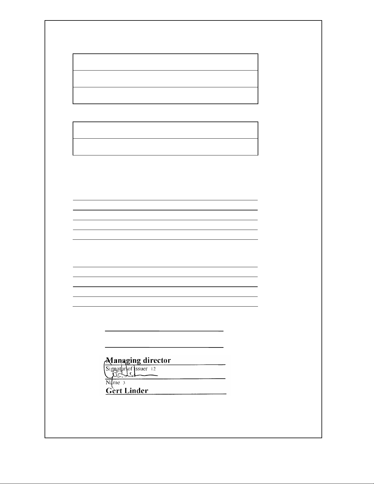
Place, date of issue
Skärhamn 980714
Position of issuer
Managing director
Signatur of issuer 12
2
Getinge Skärhamn AB
Box19 S-47121 Skärhamn
+46 0304 671020
13
10
11
1

4
4
Translation of ”DECLARATION OF CONFORMITY”
D
1. KONFORMITÄTSERKLÄRUNG
2. Hersteller
3. Name
4. Anschrift
5. Telefon
6. Erzeugnis
7. Beschreibung der Machine
8. Wir erklären in alleiniger
Verantwortung, dass dieses
Produkt mit den folgenden
Normen oder normativen
Dokumenten übereinstimmt
9. Gemass den Bestimmungen der
Richtlinien
10. Datum
11. Titel des Ausstellers
12. Unterschrift
NL-B
1. VERKLARING VAN
OVEREENKOMST
2. Fabricant
3. Naam
4. Adres
5. Telf.nr.
6. Produkt
7. Machine type
8. Wij verklaren dat dit produkt
voldoet aan de volgende
normen of normatieve
dokumenten
9. Volgens de bepalingen van de
richtlijnen
10. Datum van afgifte
11. Functie
12. Handteckning
FIN
1. YHDENMUKAISUUSILMOI
TUS
2. Valmistaja
3. Nimi
4. Osoite
5. Puh
6. Tuote
7. Viite
8. Todistamme täten ja
vastaamme yksin siitä, että
tämä tuote en
allalueltujenstandardien ja
standardoimisasiakirjojenvaati
musten mukainen.
9. Seuraavien ohjeiden
määraysten mukaisesti
10. Päivämäärä
11. Toimi yrityksesså
12. Allerkirjoitus
1. ERKLÆRING VEDR.
ENHETLIGHET
2. Produsent
3. Navn
4. Adresse
5. Telefon
6. Produkt
7. Type nummer
8. Vi overtar ansvaret for at
dette produkt er i
overensstemmelse med
følgende standarder eller
standard-dokumenter
9. I samsvar med
bestemmelsene i direktivene
10. Dato
11. Titel
12. Signatur
1. ÖVERENSKOMMELSED
EKLARATION
2. Tillverkare
3. Namn
4. Adress
5. Telefon
6. Produkt
7. Typbeteckning
8. Vi intygar och ansvarar för
att denna produkt
överensstämmer med
följande normer och
dokument.
9. Enligt bestämmelserna i
direktiven
10. Datum
11. Titel
12. Signatur
1. DICHIARAZIONE DI
CONFORMITA
2. Produttore
3. Nome
4. Indirizzo
5. Telefono
6. Prodotto
7. Riterimento maccina
8. Assumendone la piena
responsabilità, dichiariamo
che il prodotto é conforme
alle sequenti normative ed
al relativi documenti.
9. In base alle prescrizioni
delle directtive.
10. Data di emissione
11. Qualifica del dichiarante
12. Firma del dicharante
N
S
DK
1. ERKLÆRING VEDR.
ENSARTETHED
2. Producent
3. Navn
4. Adresse
5. Telefon
6. Produkt
7. Maskine ref.
8. Vi erklaerer undere
almindeligt ansvar at dette
produkt er i
ovensstemmelse med
følgende normer eller
normative dokumenter
9. I henhold til
bestemmelserne i
direktiverne
10. Dato
11. Titel
12. Signatur
F
1. DÉCLARATION DE
CONFORMITÉ
2. Fabricant
3. Nom
4. Adresse
5. Telephone
6. Produit
7. Ref de la machina
8. Nous déclarons sous notre
propre responsabilité que ce
produit est en conformité
avec les normes ou
documents normalisés
9. Conformément aux termes
des réglementations
10. Date
11. Fonction
12. Cachet et signature
I
1. DECLARACIÓN DE
CONFORMIDAD
2. fabricante
3. Nombre
4. Direccion
5. Telefono
6. Producto
7. Referncia de la machina
8. Declaramos bajo nuestra
sola responsabilidad que este
producto está en conformidad
con las normas o documentos
normalizados siguientes
9. De acuerdo con las
regulaciones
10. Fecha
11. Cargo
12. Firma
E
P
1. DECLARAÇÂ DE
CONFORMIDADE
2. Fabricante
3. Nome
4. Mozada
5. Telefone
6. Producto
7. No. artigo
8. Declararnos sob nossa
exclusiva
responsabilidade que este
producto cumpre as
sequintas normas ou
documentos normativos
9. De acordo com as
disposiçoes das directivas
10. Data
11. Cargo
12.
Assinatura

5
5
I
NTRODUCTION
Variants
These sterilizers are marketed under two brands which, apart from the names, are identical: Citomat is
aimed primarily at the dental market and the GE versions primarily at the medical sector.
Sterilizers GE224c/Citomat 164 and GE224c VAC/Citomat 164 VAC are bench sterilizers which
perform pre-programmed sterilization processes fully automatically.
Two versions of the sterilizer are available: the GE224c/Citomat 164 and the GE224c VAC/Citomat 164
VAC. The GE224c/Citomat 164 incorporates pulsed air removal and radiant post-drying, and is suitable
for sterilization of thermally stable items such as those made of metal, glass, plastic and rubber.
The GE224c VAC/Citomat 164 VAC has, in addition, air removal and drying with vacuum, which
means that it can also be used for sterilizing textiles, hollow instruments and packaged items.
General
Sterilizers GE224c/Citomat 164 and GE224c VAC/Citomat 164 VAC are bench sterilizers which
perform pre-programmed sterilization processes fully automatically. The sterilizers use steam which is
produced by a separate steam generator inside the unit. The steam generator is supplied with distilled or
de-ionised water from an integral tank.
Warning
Very important text and warnings are marked with a double border like this.
• The sterilizer operates with pressurised steam, so parts of the sterilizer may become hot.
Always take great care when working with the sterilizer.
• Only clean the sterilizer when it is cold.
• The tank cover can become very hot during certain parts of the process.
• Never lift the tank cover when the safety valve is operated.
• Take care when emptying the tank; the water may be very hot.
• The items in the sterilizer will be hot after the sterilization process.
• When the door is opened, hot steam may flow out of the chamber.
• When handling and loading items, remember that the chamber and the door are very hot.
Warranty
A one-year warranty is given on components, but not on components regarded as consumables, e.g. door
packings. For servicing work, reference should be made to agreements with the supplier.
IMPORTANT: The warranty on the delivered product is invalidated by faulty installation.
The legal rules relating to manufacturer's liability only apply if the instructions in this manual have been
followed
6
6
I
NSTALLATION
Internal transport
The simplest way of moving the sterilizer is to use a pallet truck or trolley, capable of carrying at least
110 kg.
Unpacking
Check that the product is undamaged. Notify any damage caused during transport immediately to the
transport company. Check that the items received are in accordance with the order.
Setting up
Store the sterilizer indoors at a temperature between +2 °C and 40 °C and at a relative humidity not
exceeding 95%, non-condensing.
The sterilizer should preferably be installed by an authorised technician. There should not be a cupboard
or shelf immediately above the sterilizer: it must be possible to fill and clean the water tank from the top
of the unit without difficulty.
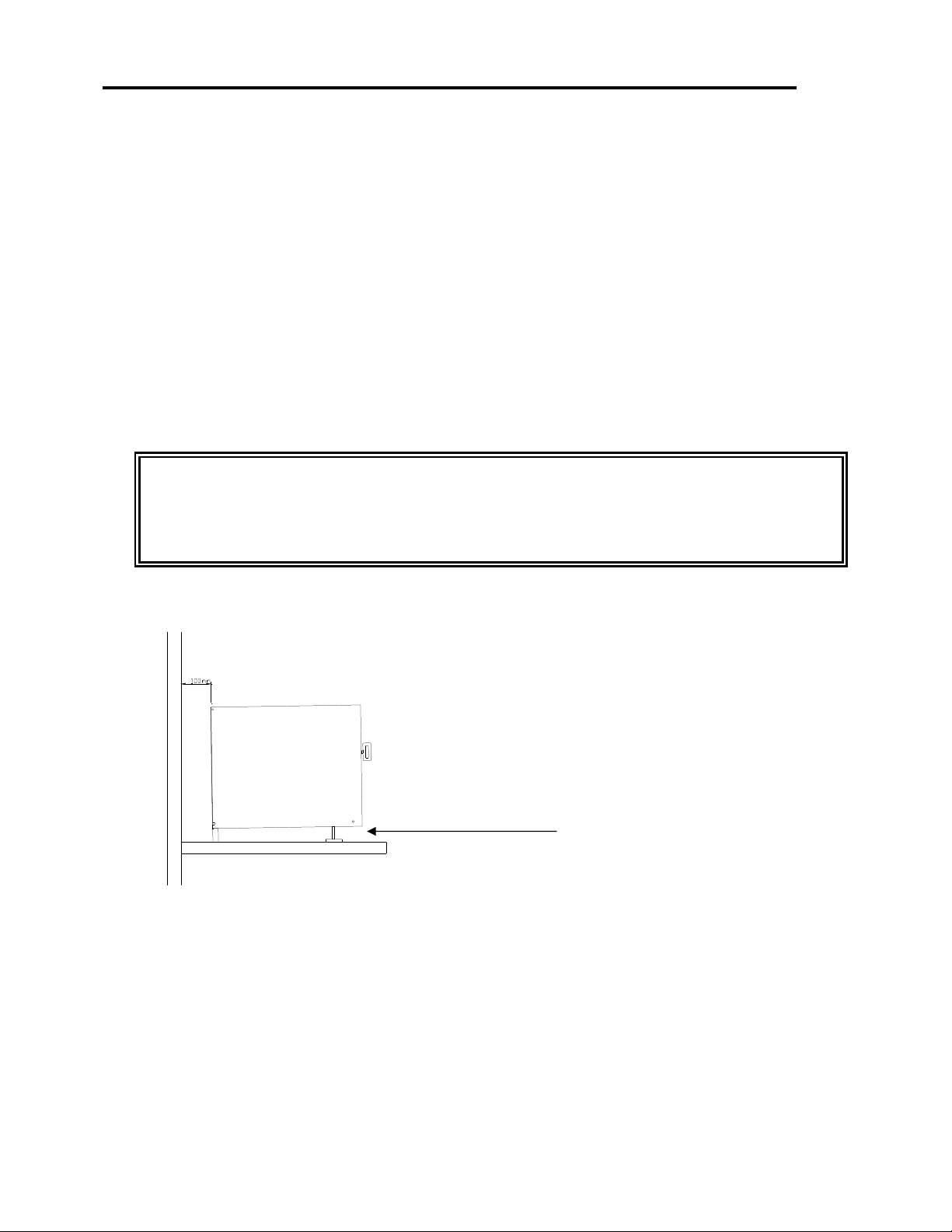
Position the sterilizer so that there is at least 10 cm free space all round it, in order to ensure
the necessary air circulation.
The ambient temperature around the sterilizer should not exceed 35 °C.
It is most important for correct performance that the chamber should slope backwards.
• Place the sterilizer on a firm base, that will not be damaged by any unintentional water spills. The
external dimensions of the unit are intended to fit on a normal worktop with a width of 600 mm.
Min.distance to wall :
100mm
Free space above sterilizer
min.: 200mm
The sterilizer must lean
backwards
Adjustable feet
• Make sure that the support surface can carry a load of at least 120 kg.
• Fit the door handle.
• Make sure that the sterilizer chamber slopes slightly backwards: adjust it using the front feet of the unit.
If the surface of the water is parallel with the line in the tank, the slope is satisfactory.
• Set up the Care Instructions and Description of Operation near the sterilizer.
• Make sure that the operator has access to, and has read, the Description of Operation.
• Collect all other documentation supplied with the sterilizer, and ensure that it is available throughout
the life of the sterilizer.
• Make sure that the technical documentation is available to the service technician.
7
7
holders for bags (to improve
• Check that there is a suitable power outlet in the vicinity of the sterilizer, and check that its voltage
agrees with that shown on the sterilizer rating plate. The outlet must be earthed (grounded) and
protected by a 10 A fuse.
Warning: Connection to an incorrect power supply may have lethal results.
• If the sterilizer has been transported at temperatures below -5 °C, it may be necessary to reset the
overheat protection device. (See the section entitled Controls for the position of the reset pushbutton.)
If the indicator lamp and display panel do not light up when the sterilizer is connected to the power
supply, this may have happened.
• Fill the water tank with distilled water or de-ionised water (maximum 30 µS/cm) to the maximum mark
(about 5 litres), from the de-ionisation equipment recommended by the sterilizer manufacture.
Warning: Putting the wrong liquids in the water tank can result in injury or other danger.
• Make sure that all operational and safety features have been checked by an authorised technician before
the sterilizer is used.
• If the sterilizer has been unused for a long time, the tank may need to be filled with water the day before
starting, to allow any air bubbles to disperse.
Commissioning / Validation
A document entitled “Points to be checked on installation” accompanies every sterilizer. Check each
point and return the document to the supplier or dealer.
If the sterilizer is used for the re-sterilization of medical instruments, the sterilizer must be validated
before being put to use. We recommend EN-554 as a model.
If a sterilized product is to be labeled with a CE-mark, the medical directive must be followed.
Indicators
If indicators are used to verify the process, we recommend those made by certified companies and
fulfilling applicable standards.
The following are used in the factory test runs.
Browne, Euro TST B & D type test pack 134° C / 3.5 min, for vacuum/steam
and the biological indicators used are of the following make:
Boule Nordic AB: Type B stearothermophilus art. no. 3014-s.
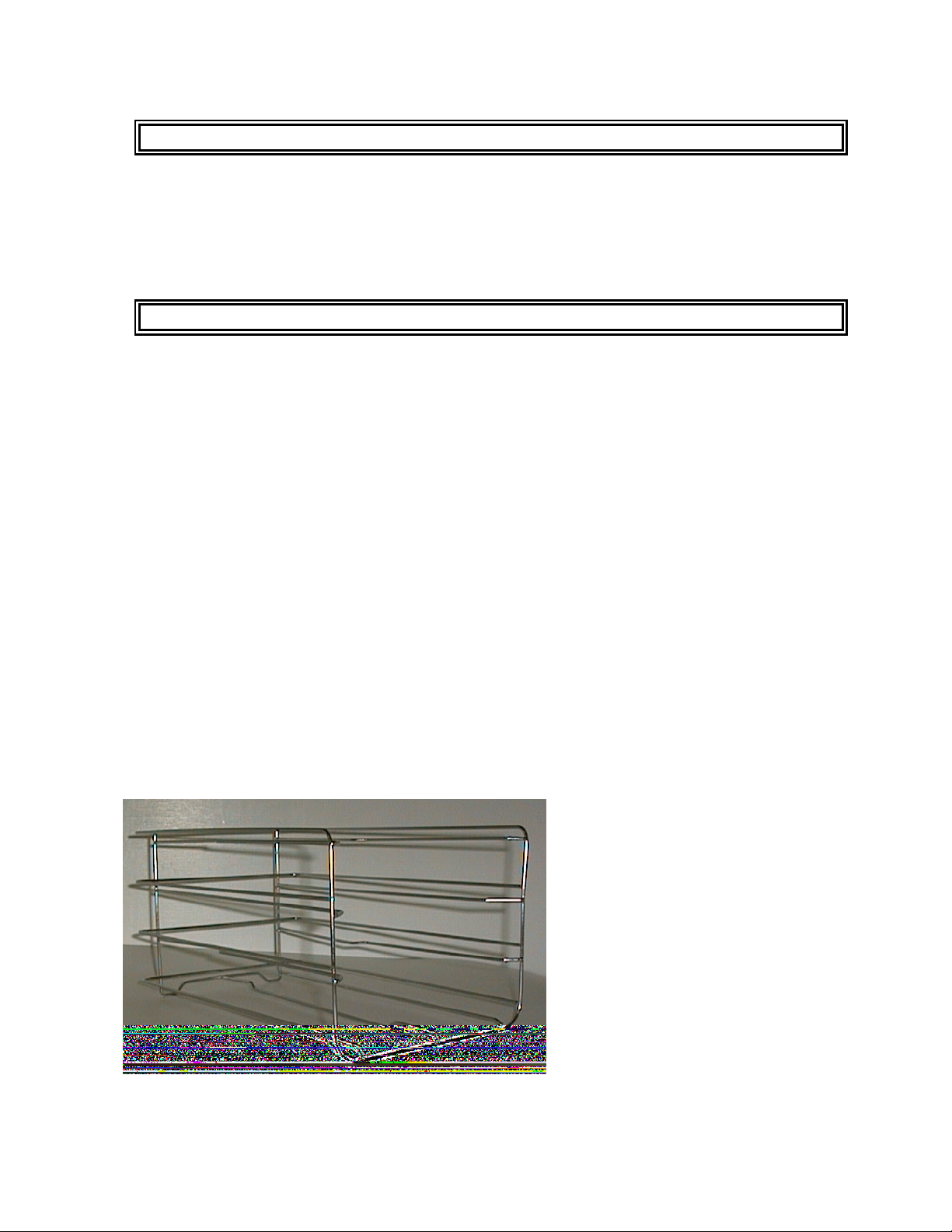
Racks
Do not use the sterilizer without the racks as illustrated below ’
Nor with any accessories
other than those supplied by
Getinge Skärhamn AB.
Examples include:
Trays - instrument baskets tray handles - special
drying results) - deionisation equipment recorder / printer.
Contact your dealer for
information.
8
5
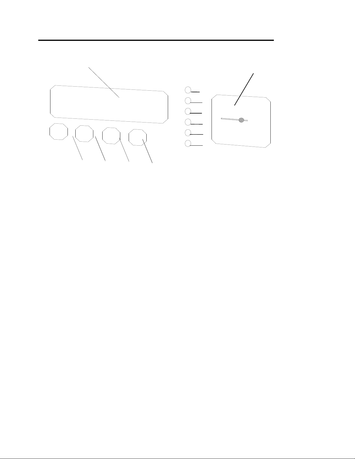
2 3 4 1
8
S
TERILIZER CONTROLS
8
12
6
7
9
10
1 Membrane key
• Program selection
2 Membrane key
• Start
3 Membrane key
• Reset (to reset faults)
4 Membrane key
• Stop
5 Display unit
• See section headed “Display unit”
6-9 Indicator lamps - yellow
• Program indication
11
10 Indicating lamp - Green
• Indicates ”Processs Finished”
11 Indicating lamp - Red
• Indicates “Error”
12 Pressure gauge
• Shows the chamber pressure
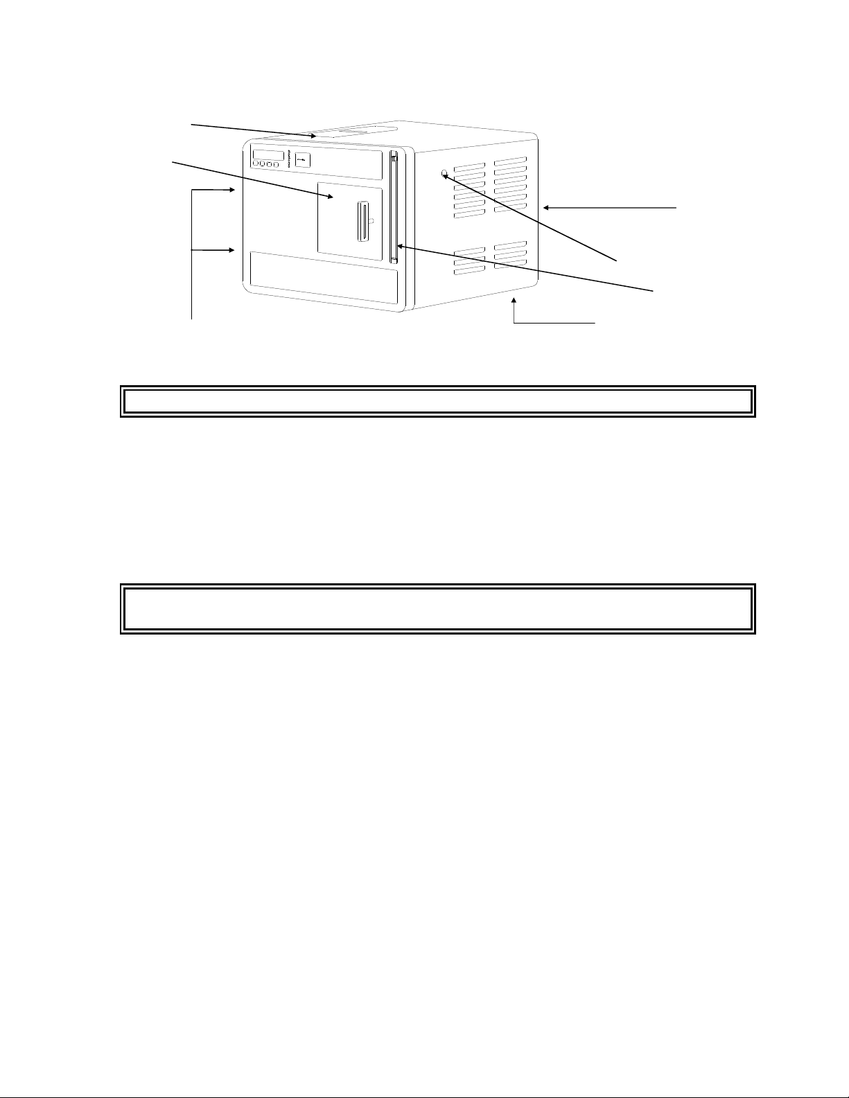
9
9
15
18
13
16
13 Front panel retaining screws
• The panel opens to the right. Unscrew the fixing screws first.
External panels must not be removed by anyone other than an authorised technician.
19
14
17
14 Manual safety valve operator (easing gear)
• Operating this during sterilization phase opens the safety valve.
15 Tank cover
• Covers the water tank.
16 Reset pushbutton, overheat protection (underneath the unit, left-hand side)
• See under ‘Installation/Setup’.
Never reset the overheating protection device without first removing the power plug from
the electrical supply socket.
17 Level tube
• Shows the water level in the water tank.
• The level tube can be disconnected at the top and hinged forwards and downwards to empty the water
tank.
18 Door handle
• For closing and locking the sliding door.
• Closing - using the handle, slide the door carefully to its right-hand end position.
• Locking - turn the handle 90° clockwise.
19 Main on/off switch, fuses and connector
• On the rear left side of the unit.
• Fuses 2 x 10A (anti-surge).

10
10
D
ISPLAY
The sterilizer has a display which provides the user with information in the form of text.
The following information is shown on the display:
Text on display Explanation
1. Heating up The sterilizer is heating up
C<70oC SG<140oC Chamber temp.Current temp. Steam generator.
2. Select 0103 Select program with “PROGR” Number of cycles run
134 oC Textile Current program. (Starting position between
sterilization cycles)
3. Close the door. Prompt to close and lock the door
(Operator has pressed start with door open)
During the process
4. 2,1 134 13 Current pressure - Current temp.- Minutes after start
Sterilization Current sequence
After completion of the process
5. 0,0 100 15 Current pressure - Current temp. Process time, min.
Finished Process is complete but door has not been opened.
6. Fault codes See “Malfunctions”
Incidental note concerning the indicated pressure after completion of the process:
As the pressure is measured by an absolute pressure sensor, the indicated pressure (when the door is closed and locked) is the
current atmospheric pressure (ie a barometer). It is displayed until the door is opened.
11
11
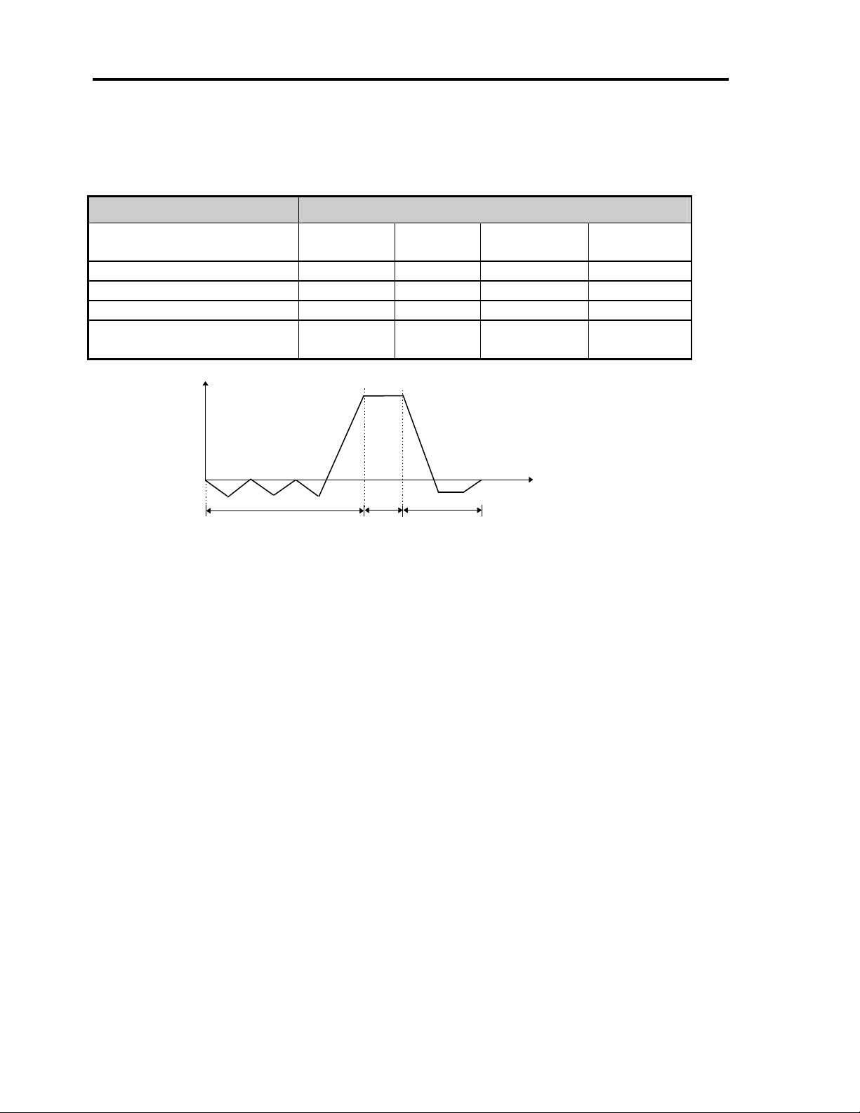
Pressure
pressure
D
ESCRIPTION OF THE PROCESS
The use of a microprocessor in the sterilizer means that it can offer a large number of program
variations. The programs shown below are supplied as standard.
Parameter
Temperature min oC 121 134 134 134
Pressure min kPa 104 203 203 203
Sterilizing time minutes 20 3.5 5 5
Total time empty chamber
(approx) minutes
Atmospheric
The sterilizer may include further programs or modified programs, as described in its test records.
NB: The program times shown above are approximate, and may be altered if standards or other factors
result in modified program sequences.
121Wrapped 134Flash 134 Wrapped 134 Textiles
33 7 18 23
Pre-treatment
Schematic pressure/time diagram for sterilizer with vacuum
Sterilizing
Post-treatment
Process
Time
Flash program
The flash program must only be used for solid unwrapped instruments.
Note: Non wrapped sterilized instruments are either intended for immediate use in the same room where
the sterilizer is placed, or for non sterile storage, transport and application (eg. to prevent cross infection)
Bowie & Dick Helix
In addition to the previous standard programs, the sterilizer is equipped with test programs for "Bowie &
Dick" and the Helix test. This is indicated on the display when the program is selected. A flash program
shall be run immidiate before a B&D helix program.

12
12
T
HE STERILIZATION CYCLE
Type of material
The sterilizer has programmes for treating heat-stable materials such as metal, glass, plastic and rubber,
unpacked or packed in paper or paper/plastic bags. The packaging material must comply with EN-868.
Heating
An unheated appliance is required. Turn on the power.
Technical: The element that preheats the steam generator and chamber is connected to the power
supply. The display shows ”Heating”. The temperature of the heater can be followed on the display as
soon as the temperature exceeds 150° on the heater. When the temperature reaches 240°, ”Select” is
shown on the display and the sterilizer is ready to start.
Pre-treatment
The pre-treatment part of the cycle purges the air from the sterilization chamber and the items in it. The
air obstructs the necessary contact between the steam and the micro-organisms to be killed.
The moistening that is crucial for eliminating the micro-organisms also takes place during the pretreatment phase.
There may also be a preheating phase, the purpose of which is to raise the temperature of the items to be
sterilized to a higher temperature before the real start of the pre-treatment phase. This reduces the
quantity of condensate resulting from the subsequent admission of steam and thus, finally, drier items.
Technical: The pre-treatment consists of a) blowing-through when pump 1 and MV-1 are opened
alternately for a particular time, b) pressure reductions when MV-1, fan and pump 2 are connected to the
power supply to a pre-programmed value (e.g.–0.6 bar), c) pressure rise when pump 1 starts and runs to
a pre-programmed value. The sterilization pressure must be reached in the last rise in pressure. When
sterilization pressure and sterilization temperature have been achieved for temperature sensor T0,
”sterilization” appears on the display.
Sterilization
It is during the sterilization phase that the micro-organisms are actually killed.
The sterilization phase lasts for a preset number of minutes at the preset temperature and pressure.
Technical: The sterilization phase continues for a pre-set number of minutes at pre-set
temperature/pressure. The pressure is regulated using pump 1, which is started as required.
Post-treatment
The purpose of post-treatment is to reduce the moisture content of the items being sterilized.
During post-treatment, the pressure falls to atmospheric pressure or lower, depending on which program
was selected.
Most programs in sterilizers with vacuum function have a “vacuum phase", in order to reduce the
boiling point of the residual condensate, thus leaving the items drier.
At the end of the vacuum phase, air is drawn in through a sterile filter until the chamber reaches
atmospheric pressure.
Technical:
pre-programmed value, a clock is started. When the time has elapsed, MV-1 closes and MV-2 opens, air
being drawn in via the air filter and the pressure rising towards atmospheric pressure.
MV-1, fan and pump 2 are connected to the power supply. When the pressure reaches the

13
13
O
PERATING INSTRUCTIONS
Preparations from cold (all lamps unlit)
• Check that the tank is filled with water to the maximum level. When filling, use only distilled water or
de-ionised water (maximum 30 µS/cm).
• Start pre-heating the sterilizer by connecting it to the mains power supply in accordance with the
Installation instructions. The following indications appear:
• “Heating up” on the display.
• After about 45 minutes, when the sterilizer has reached operating temperature the word 'Select' will
appear on the display.
• If the sterilizer has been turned off, start a flash-program without material.
Sterilization
Carefully follow suppliers' instructions for all items to be sterilized.
Sterilize only items that are intended to be steam-sterilized, and so can withstand at least
125 C.
• Check of the level tube, that the water level in the tank is not below the minimum level.
• The goods must be completely dry when loaded into the chamber.
• When closing the door, make sure that nothing (e.g. bags etc.) is caught between the door and the
chamber. If this is the case, operational problems will occur.
• Items to be sterilized must be freely exposed; in other words, instruments and packages must not be
piled on top of each other.
• If a particularly heavy load is being run, the textile programme is recommended
• When sterilizing lubricated dental hand pieces, wrap them in a paper towel which will absorb any
excess oil.
1. Place moisture-sensitive items and low-mass items at the top of the chamber.
2. Place heavy items at the bottom of the chamber.
3. Place bowl-shaped items so that the hollow part is facing downwards.
4. Place empty containers (bottles, test tubes etc.) with their opening downwards.
5. Position bags vertically, to assist run-off of condensate. This makes it more likely that the items will be
dry on conclusion of the process.
6. Choose the required sterilization program with the membrane key “PROGR”. The display shows text to
indicate the program that has been selected.
7. Close the door and turn the handle 90° clockwise to the locked position, i.e. horizontal.
8. Let the items rest in the chamber for a few minutes before starting the process. This warms them up, so
that less condensate is formed, and the items are drier at the end of the process.
• Press the membrane key “START” to start, the yellow indicator lamp for required program lights up
and the sterilization process will then proceed fully automatically.
• The process is complete when the display shows 'Finished', the green indicator lamp lights up and the
pressure gauge shows zero.

14
14
The display never shows “Finished” if the process has been interrupted.
If the display is not showing “Finished”, items in the chamber may have been put there by
someone else, and not yet been sterilized.
• The goods will get drier if they are left in the sterilizer chamber for a few minutes with the door slightly
open.
• As soon as the door is opened, the 'Finished' message disappears from the display.
• If the red indicator lamp is lit after a sterilization process, the items must be regarded as non-sterile and
must be re-sterilized.
• Opening the door causes 'Finished' to disappear from the display and be replaced by 'Heating' or '
Select', depending on the temperature of the steam generator and the chamber
• If you need to stop the process , press the membrane key “STOP” . The red indictor lamp lights up and
the display shows fault code 030 “Process stopped”; see under “Process interrupted.”
• Then press the membrane key ”RESET” and wait for the pressure gauge to show zero.
Between sterilizations
• Close the sterilizer door, but do not turn the handle.
Be sure to remove all items from the sterilizer chamber as soon as the sterilization process is
finished.
Never leave items in the sterilizer chamber.
• The sterilizer works best when the water tank is filled to the max mark with distilled or de-ionised
water.
• When using the 121°-program after a 134° program has been running. Choose 121°-program and wait
at least 15 min before start.
Closing down for the day
Unless local routines state otherwise.
• Close the sterilizer door, but do not lock it.
• Leave the sterilizer connected to the electric power supply.
At least six hours before “periodic maintenance”:
• Leave the sterilizer door fully open, ie as far to the left as possible.
• Shut down the sterilizer by unplugging the mains plug from the socket; the indicator lamps go out and
the sterilizer cools down. (See also under “Maintenance”)

15
15
M
ALFUNCTIONS
• Start by checking that the sterilizer is connected to the mains power supply.
• Check the main fuses. Shut down the sterilizer. The fuses are in a red box in the same unit as the main
switch. Fuse rating: 10 A anti-surge.
• Check that the red indicator lamp is not lit.
• Check that the tank contains distilled or de-ionised water.
• Check that nothing is between the chamber and the door.
• Check that the display reads”Select”.
• If the display is not lit, one of the overheating protection devices may have operated. Contact an
authorised technician.
Fault codes
The display may show any of several fault codes. If a fault code appears, the red indicator lamp lights up
as well. Items in the chamber must be regarded as non-sterile and must therefore be re-sterilized.
Never attempt to open the door until the pressure gauge has returned completely to zero.
Fault code 040 Pressure error
Pressure outside pressure band during sterilisation time
Fault code 041 Temp. Error
Temperature outside temperature band during sterilisation time
Fault code 050 Program missing
Type of sterilizer does not correspond to the type of sterilizer programmed in the service program
Fault code 017 Time out
Max. temperature was not reached within time limit
Fault code 018 Time out
Min. pressure was not reached within time limit
Fault code 019 Time out
Max. pressure was not reached within time limit
Fault code 043 “Door open”
The safety switch for the door was operated during process.
Fault code 014 “Proc. interrupted”
A power failure interrupted the process.
Fault code 042 “Steam generator cold”
The sterilizer has been overloaded or left with the door open between sterilization operations.
Fault code 030 “Process stopped”
The process has been stopped with the membrane key “STOP” .
Fault code 070-074 “PT-100 error”
One of the temperature sensors is open circuit.
Contact an authorised technician.
Service / Spare parts
For service or spare parts, contact your dealer.

16
16
P
ROCESS INTERRUPTED
If the sterilizer stops during the programme, check the following:
That no material has become caught between the door and chamber.
That the water level in the tank is not too low.
That the sterilizer slopes to the rear in accordance with the installation instructions.
That the strainer in the bottom of the tank is not obstructed.
That the strainer nside the chamber is not obstructed.
That the sterilizer is set up so that there is at least 10 cm space all round it.
If a process in progress has to be interrupted
Press the membrane key ”STOP”, whereupon the message ”Post-treatment” will appear on the display
and a red lamp will light up.
Wait until the pressure gauge shows zero and the message ”Process interrupted” appears on the display.
Press the membrane key ”RESET”, whereupon the red lamp will go out.
Open the door by turning the handle anticlockwise a quarter turn, but do not slide the door sideways
until about a minute has passed.
N.B. There is a risk in connection with an interrupted process of steam streaming out of the
chamber when the door is opened.
Stop / Alarm
If the sterilizer has stopped or if a red indicator lamp lights up while a process is progress, follow the
procedure below in the sequence indicated:
Alt.1 Press the membrane key “RESET” . The red indicator lamp goes out.
Operate the door switch by turning the handle anticlockwise. The display should show 'Heating
up' or 'Select'. Turn the handle clockwise to the closed position. The sterilizer is now in its
starting state.
Alt.2 Disconnect the sterilizer from the electric power supply and reconnect it after about 20 seconds.
The red lamp lights up and the display shows fault code 014 'Process interrupted'.
Press the membrane key “RESET” The red indicator lamp goes out.
When the pressure gauge shows zero, open the door by turning the handle anticlockwise. Wait
at least ten seconds before opening the door fully. The display shows 'Heating up' or 'Select'.
The sterilizer is now in its starting state.
Alt. 3 Disconnect the sterilizer from the electric power supply and reconnect it after about 20 seconds.
Manually operate the safety valve release to return the pressure in the chamber to atmospheric
pressure.
When the pressure gauge shows zero, open the door by turning the handle anticlockwise. Wait
at least 10 seconds before fully opening the door.
Close the door, but do not turn the handle.
Reconnect the electric power supply. The red indicator lamp lights up and the display shows
fault code 014 “Process interrupted”.
Press the membrane key “RESET” . The red indicator lamp goes out. The display shows
'Heating up' or 'Select'. The sterilizer is now in its starting state.
Follow the instructions in the section entitled “Operating Instructions”.
If the fault persist, call a technician.

17
17
SAFETY DEVICES
Each sterilizer incorporates components intended to ensure safety of operation and maintenance. These
components have been specially selected, and therefore must not be replaced by other makes or types of
devices unless approved by the manufacturer.
Door
The door is designed so that it cannot be opened without force if the pressure in the chamber exceeds
+0.2 bar. If force is applied to open the door at this pressure, a reed relay will be operated to open the
exhaust valve to discharge the steam in the chamber. If, despite this, the door is opened with force so
quickly that steam escapes via the door opening, it will nevertheless be directed to the sides, behind the
external cladding of the sterilizer and not scalding the operator.
Safety switch - door
This prevents the sterilizer from being started unless the door is correctly closed and secured.
Pressure vessel
The sterilizer chamber is a pressure vessel, designed and manufactured in accordance with pressure
vessel standards and requirements, as issued by the competent authorities for this area. Compliance with
the standards is checked and tested by the Swedish Pressure vessel authorities(SAQ).
Safety valve
The chamber is fitted with a safety valve, set at an appropriate opening pressure, and which also
incorporates a manual device for operating the valve to check its performance and for use during
maintenance.
Overheating protection
The steam generator and chamber are fitted with overheating protection devices.
Safety checking
• During the sterilization process, check that the door is sealing against the steam pressure.
• Check that the sterilizer cannot be started until the door is correctly closed
• Make sure that all personnel are aware of current pressure vessel standards, together with the associated
obligations
• Make sure that all personnel understand all the warning notices.
• Check that the safety valve operates at a pressure of 2.7 bar.

18
18
M
AINTENANCE
Maintenance requirements depend primarily on how heavily the sterilizer is used. This means that the
frequency of maintenance operations may vary from case to case. The manufacturer recommends that,
when the sterilizer is being used to full capacity, at least the following maintenance operations should be
performed at the specified intervals:
Periodic cleaning every 50 cycles or at least once a month
Unplug the electric plug from the socket before cleaning the unit.
The equipment must only be cleaned when it is cold.
External covers must never be removed by anyone other than an authorised service
technician..
• Drain the water from the tank by releasing the level tube at the top and tilting it forwards and
downwards.
• Clean the strainer at the bottom of the tank.
• Fill the tank with distilled or de-ionised water to its maximum level.
• Remove the chamber insert. Clean the chamber internally using a damp cotton rag. Never use steel
wool. Make sure that the strainer at the far end of the chamber, on the bottom at the right, is clean.
• Wipe down the outside of the sterilizer using a chlorine-free domestic cleaner.
• If the sterilizer is used for sterilizing lubricated dental hand pieces, the water in the tank must be
changed every 20 cycles.
Monthly
To ensure that the safety valve is working properly, it must be regularly operated as follows:
• Start a sterilizing cycle and wait for the sterilization phase
• Operate the easing gear at the “Safety valve” sign, which is accessible from the outside.
Quarterly
• Check the sterilization performance of the sterilizer, using special bacteria samples under normal
operating conditions..
Yearly
• The sterilizer must be serviced by an authorised technician.

19
19
YEARLY MAINTENANCE SERVICE
Serial no:......................................Address:................................................................
Replace the door gasket.
Lubricate the moving parts of the door with a heat-resistant grease.
Clean the rails on which the ball-bearings run.
Fit a calibrated inspection pressure gauge, for measurement of absolute pressure, to the flange
intended for it and check, when the sterilizer is in use, that the sterilizer's own pressure gauge is
maintaining the required accuracy class.
Using a calibrated thermo-instrument, check that the pre-heating temperature of the chamber is
correct.
Using a calibrated thermo-instrument, check that the steam generator is maintaining the correct
operating temperature.
While the external covering has been removed, inspect the unit for any leaks in pipe joints or
instrument connections, and correct them if found.
If necessary, perform any maintenance to be carried out by the operating personnel
Check the performance of electrical components by using the Component Test feature in the
service program.
Run all programs.
Replace the air filter, at least every 1500 cycles or once a year
Check all safety features following point 1-6.
1. During the sterilization process, check that the door is sealing against the steam pressure.
2. Check that the sterilizer cannot be started until the door is correctly closed
3. Make sure that all personnel understand all the warning notices.
4. Check that the safety valve operates at a pressure of 2.7 bar.
5. If the sterilizer includes programs for the sterilization of liquids, make sure that personnel
understand the risks associated with such applications.
Miscellaneous
Changed details:
Date: Sign:
To forfill the medical device a service according to above specification has to be
made and signed by an authorized technician The document has to be archived at
the users site until the sterilizer is taken out of use.

20
20
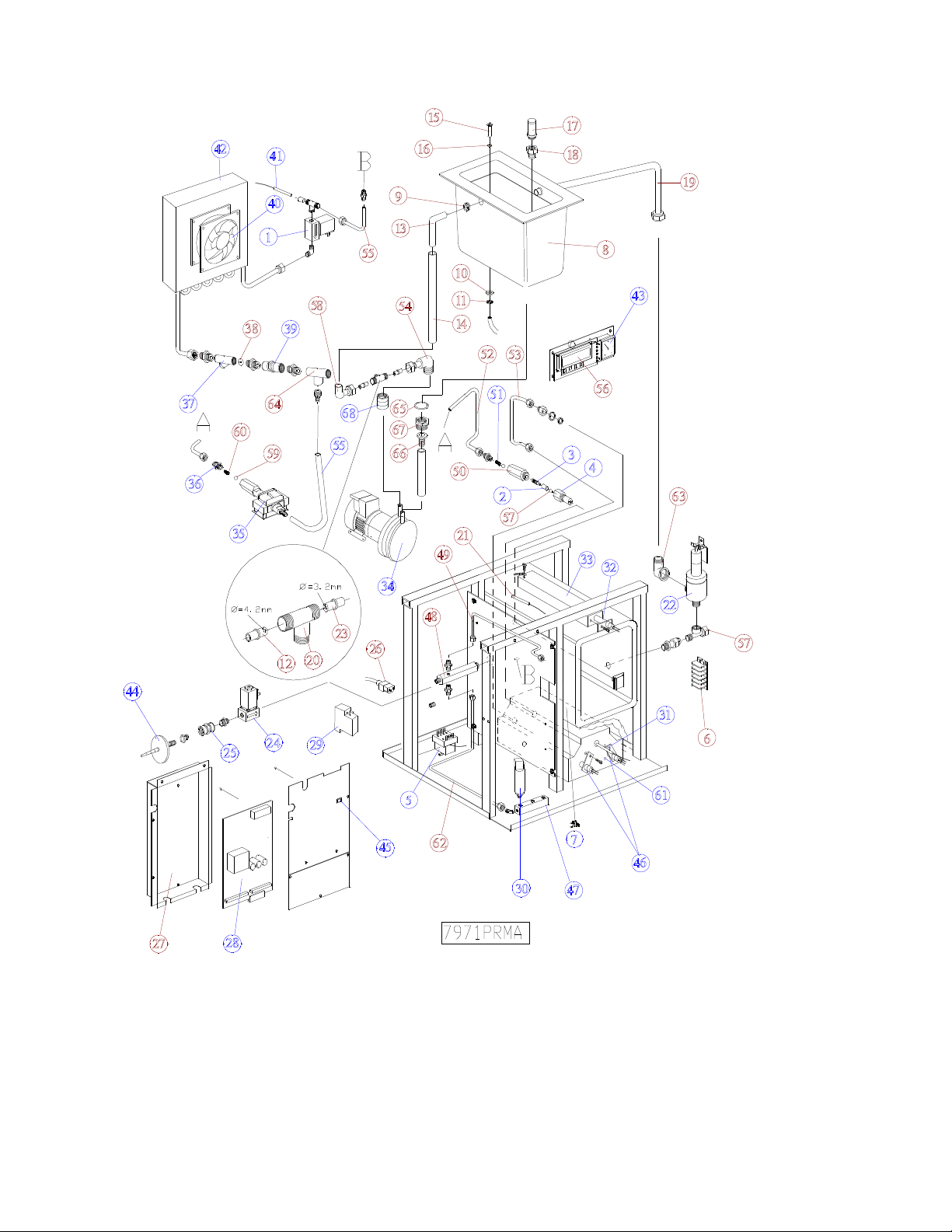
D
ESIGN OF THE STERILIZER
General
For flowchart, see Appendix 1
The sterilizer has a closed steam generating system; this means that evaporated water is condensed and
returned to the water tank.
Pump P1 is a vibration-type pump which pumps the water from the tank to the steam generator, which
turns the water into steam. The steam generator is supplied with distilled or de-ionised water from an
integral tank. The temperature of the steam generator is proportionally controlled to 250 °C in service,
by means of temperature sensor T4.
The temperature of the chamber walls is proportionally controlled to the set value by means of T1.
The pressure in the chamber rises when steam is supplied to it. The pressure is monitored by a pressure
sensor which, via a PID regulator, controls the frequency of pump P1. The steam temperature is
monitored by temperature sensor T0.
Solenoid valve MV1 is used to empty the chamber. The steam flows to the condenser where it is
condensed with the aid of a cooler and a fan. The resulting water is returned to the water tank.
Pump P2 powers an ejector that creates a vacuum to reduce the pressure in the chamber below
atmospheric pressure.
Solenoid valve MV2 admits air, filtered through the air filter, to the chamber.
Reference: (see X/Y) = Annex X / position Y
Components
Use only insulated tools when doing any work that requires the equipment to be energised.
Remove the power supply plug from the socket when doing any other work.
Solenoid valves
Noisy solenoid valves are trying to tell you something! The humming noise may be a warning of
incipient overheating of the coil, due to an air gap in the magnetic circuit. This is often caused by dirt on
the moving core, preventing it from closing properly when energised by the magnetic field from the
winding. This creates a small air gap in the magnetic circuit, reducing the inductance of the coil and thus
increasing the current through it.
• Deal with a humming solenoid valve by cleaning both the plunger and the cavity in which it runs.
• Always replace the O-ring between the coil and the casing after removing the coil.
Solenoid valve MV-1
This valve is fitted at the back of the sterilizer (see 6/1), and controls the evacuation of air and steam. It
opens when it is energised, and is open when the sterilizer is in the standby state. The valve closes if the
door is opened.
Solenoid valve MV-2
(see 6/24), This valve controls pressure equalisation after the post-vacuum phase. It is energised and
open when the sterilizer is in the standby state. The valve closes if the door is opened.

21
21
Inlet nozzle to steam generator
This is fitted at the back of the steam generator. Inside the nozzle (see 6/4) there is a swirl outlet (see
6/2) and a strainer (see 6/3). The strainer and the hole at the front of the nozzle can easily become
blocked if the sterilizer is not cleaned or is operated with water that is not de-ionised /distilled.
Checking:
This is done in the service program; see the relevant section. Select “Component test”, and activate
“steam pump”. The pressure should rise to 2.7 bar, at which the safety valve should open.
Steam generator overheat protection, Öv300
The steam generator is protected against harmful temperatures above 300 °C by the Öv300 thermal
cutout (see 6/5) which must be manually reset after it has operated. The reset pushbutton is accessible
from outside the unit, and is fitted beneath the left-hand corner of the sterilizer. If the thermal cutout has
operated, current to all components is cut off.
Chamber overheat protection, Ök200
This thermal overload cutout has a fixed operating temperature of 200 °C, and is fitted slightly above the
centre of the left-hand side of the chamber (see 6/7). Its purpose is to prevent the overheating of the
chamber heater or chamber. If it operates, it cuts off the electric power to all components.
General, regarding the overheat protectors
The chamber overheat cutout may operate because:
• the sterilizer has been transported at temperatures below freezing.
• of a fault in the temperature control of the steam generator / chamber preheating system.
• If the thermal cutout has operated as a result of excessive temperature, the sterilizer must be allowed to
cool down for a while before the reset pushbutton will stay in.
When resetting the cutout, always pull out the plug from the supply socket.
Check:
Because of the undue thermal stress on the equipment, it is advisable to refrain from realistic checking
of the operation of the chamber overheat protection.
Chamber pre-heating element
This element preheats the chamber to about 125 °C in 134 °C programs and 115 °C in 121°C programs.
The element is rated at 900 W, so its resistance is about 60 Ω. (see 6/32)
ip-on ampmeter to check that the heaters are drawing current.
Steam generator elements
These preheat the steam generator to about 250 °C.
The element is rated at 900 W, so its resistance is about 60 Ω. (see 6/46)
Checking the elements:
These checks are part of the service program; see the relevant section. The check involves a “component
test”, in which “chamber heat” or “heat 1” and then “heat 2” are activated. Use a clip-on ampmeter to
check that the heaters are drawing current.
NOTE: The heaters deactivates after 20 seconds in the “component test”.

22
22
Pump 1
This pump supplies the steam generator with water from the tank via check valve (non-return valve)
BV-1 and a spray nozzle fitted into the back of the steam generator heating block. The pump is a
vibration pump (see 6/35) The frequency of its power supply is controlled by the control system.
Checking is done in the service program; see the relevant section. Select “Component test” and activate
“steam pump”. The pressure in the chamber must rise to 2.7 bar, at which pressure the safety valve must
open. The flow rate is 100-200 ml/min.
Warning: Risk of scalding from discharged steam when the safety valve operates.
The cover of the water tank becomes hot when the safety valve operates or is operated.
Pump 2
The purpose of this pump is to pump water from the tank through the ejector and then back to the tank,
to produce a vacuum in the sterilizer. Pump 2 is a centrifugal pump (see 6/34).
Check the pump as part of the service program; see the relevant section. Select “Component test”, and
activate “Ejector on” and “Valve 1”. If there is nothing wrong with BV1, the pressure should fall to at
least -0.8 bar after about 15 minutes.
Check valve BV1
This check valve (non-return valve) is fitted immediately after the vibration pump (see 4/6) and prevents
steam being forced backwards through Pump 1 to the water tank.
Check valve BV-2
This check valve (non-return valve) is fitted between the air filter and solenoid valve MV-2 (see 6/25)
and prevents steam flowing through the filter in the event of a fault in solenoid valve MV-2.
Check valve BV-3
This valve is fitted between the cooler and the ejector (see 6/39) and prevents pressure equalisation after
the post-vacuum phase by any route except through the filter at solenoid valve MV-2.
Air filter
The purpose of the air filter is to supply the sterilizer with sterile filtered air after the post-vacuum phase.
The filter must be replaced after 1500 cycles or annually. (see 6/44)
Pressure gauge
This indicates the pressure in the chamber, even if the power supply is turned off (see 6/43)
Checking: Use an independent calibrated pressure gauge (see 6/47) and compare its readings with those
on the sterilizer pressure gauge.
Absolute pressure sensor
Monitors and controls the sterilizer process (see 6/30).
Checking:
Use an independent, calibrated absolute pressure gauge (see 6/47) and compare its readings with those
on the display. Range: 0-4 bar absolute corresponds to 0-5 V DC. Output signal at atmospheric pressure
about 1.25 V. See also the Service Program section.
Adjustment:
Follow the instructions under “Service program”, but before doing so, check the “Range” and “Offset”
values set during pre-delivery inspection.

23
23
Temperature sensors
The sterilizer has Pt-100 sensors to monitor:
a) Steam generator (T4) (see 6/31)
b) Chamber preheating(T1) (see 6/21)
c) Sterilizing process (T0) (see 6/41)
Note:
If the sterilizer includes programs for sterilization of liquids, there may be additional Pt-100 sensors.
Checking:
Disconnect the sensor from the control system and check it with an ohmmeter. Its resistance should be
about 100 ohm; the higher the temperature the higher the resistance. See also the Service program
section.
T4. The temperature sensor for the steam generator is fitted at the front of the steam generator. It
controls the steam generator temperature (about 250 °C), and also interrupts a process if the steam
generator temperature falls below the pre-programmed value of about 150 °C while a sterilization
process is running.
Checking:
This requires the sterilizer to have been turned on for at least an hour. Insert an independently calibrated
measuring instrument, capable of measuring to at least 300 °C, in the measurement hole at the front of
the steam generator (see 6/61) and wait for the temperature reading to stabilise. It should now show a
temperature of between 240 °C and 255 °C. Also compare the temperature during the heating phase,
when the steam generator temperature is below 160 °C, comparing the value on the sterilizer display
panel with that shown on the instrument.
T1.. The chamber sensor is mounted on top of the chamber, and controls the chamber temperature to the
programmed value of about 120 °C.
Checking:
This requires an independently calibrated temperature instrument inserted about 150 mm between the
thermal insulation and the chamber on the right-hand side of the sterilizer. Make sure that there is good
thermal contact between the thermometer and the wall of the chamber. When the sterilizer is ready for
use, this independent instrument should show a temperature of about 120 °C.
Note: If the temperature is to be checked soon after a sterilization program has been run, the chamber
must be allowed to cool down, for example by turning the sterilizer off and leaving the door open for
about 15 minutes.
Note: The chamber temperature shown on the display during the heating phase may not agree with the
value shown by the independent calibrated thermometer. This is because the measurement points are
relatively far apart.
T0. The sensor that monitors the sterilization process, and which provides the signal to the display of
chamber steam temperature, is fitted in a manifold on the left of the sterilizer.
Checking:
Use an independent calibrated temperature measuring instrument, inserted in the chamber through the
connection on the left-hand side of the chamber near the safety valve. Check that its reading with that
shown on the display. Alternatively the temperature can be calculated from the pressure reading of a
separately connected absolute pressure sensor. (104 kPa ≈ 121 °C, 203 kPa ≈ 134°C.
Ejector
The ejector is fitted in the pipe from pump 2 to the water tank (see 6/23), with its suction line connected
to check valve BV3.
The ejector is in the form of a T-piece, containing two ejector nozzles. Note that these nozzles are not
identical. The smaller holes in each of the nozzles must face each other, and the nozzle with the largest
hole must be fitted in the outlet of the T-piece towards the tank.

24
24
Safety valve
Opening pressure 2.7 ± 0.14 bar
Blow-off pressure max 2.97 bar
The function of the safety the valve is to relieve the pressure in the chamber if it rises out of control (see
6/22). Check the safety valve with the sterilizer running normally.
• Check that the safety valve is not leaking water or steam.
• Check that the lead seal of the safety valve is intact.
Checking the blow-off pressure of the safety valve:
This is done in the service program; see the relevant section. Select “Component test” and activate
“Steam pump”. The safety valve must blow off when the pressure reaches 2.7 ± 0.14 bar. Use an
independent pressure gauge for this check.
Adjustments or modifications that change the blowoff pressure of the safety valve may be
performed only by an authorised person.The safety valve should be operated regularly, at
least four times a year. See heading“Maintenance”. The lead seal must not be broken by
anyone other than an authorised person.
Circuit board (see Appendix 3) (see 6/28)
The display unit and the circuit board unit must always be stored in their conductive bags
until they are to be fitted to the sterilizer.
Before handling any of the electronic spare parts, make sure that you are not
electrostatically charged, by touching earthed radiator, for instance.
• Each output is controlled by a triac, so that there is electrical isolation between the electronics and the
control voltage to the components.
To check the operation of a triac, activate the relevant output in “component test” and connect a
voltmeter between pin 1 (Line N) and the relevant output pin.
the voltmeter shall read ≈230V
• A LED is connected to each output. It is lit when the output is active, ie when it is supplying current to
its component (valve, pump, element etc.).
Another LED (H1) is lit when the door is locked
• Programs are stored in a PROM. Markings on the PROM show the program version.
This is how to change the PROM:
1. Note the calibration settings of the pressure and temperature sensors, the cycle counter and which
inputs are activated on sensor open-circuit detection (see Appendix 5), as well as the date of the
software. This date is in the service program menu; go to the service program and press the PROGR
button. (see 6/45)
2. Switch off the electric power supply to the sterilizer.
3. Change the PROM.
4. Switch on the power.
5. Note the old cycle counter value on the inside of the circuit-board cover.
6. Check the calibration settings and sensor activation.
• When changing circuit boards, move the old processor and the PROM to the new board.

25
Door
25
Changing the door seal
Unplug the electric power lead when changing the door seal.
• Unscrew the screws and swing out the front.
• Loosen the left-hand side panel fixing screws near the Display and push the side panel back a few
centimetres.
• Open the door, move away the stop which limits lateral movement and lift off the door.
• Remove the old seal and clean the seal groove, taking care not to damage it.
• Place the new seal on the door and position it so that it covers the groove. Note: The seal is rectangular.
• Note: The seal is a parallel trapezoid in cross-section. Position the seal to that the right angles of the
cross-section are down in the groove.
• Start by pressing down the corners, then the middle, and finally the entire seal.
• Refit in reverse order.
Adjusting the door
After adjusting the door, check that all nuts and screws are tight.
Take care: some parts may be hot if the sterilizer has recently been used.
The door adjustment procedure described here may only be needed in exceptional cases, eg if the door is
too stiff to lock or if there is leakage that cannot be traced to any other part of the sterilizer.
It is advisable to replace the door seal before the door is adjusted.
Before the door is adjusted, chamber preheating must be checked. The procedure for this is described
under a separate heading.
• Check that the seal groove and the front of the chamber are undamaged and free from deposits.
• Do the adjustments with the sterilizer heated up.
VERTICAL ADJUSTMENT
The door moves a short distance vertically on interlocking. To allow for this movement, the vertical
adjustment of the upper bar (see 2/7) must be correct.
• With the door open and about 15 mm from its right-hand end position, check that there is a depth
clearance of about 1 mm at both upper ends of the door.
Adjustment:
• Slacken the nuts (see 2/6) so that the bracket (see 2/5) can change its position.
• Adjust the position of bracket (see 2/5) with screws (see 2/1) . Use the middle screw to pull the bar up
and the outer screws to push it down.
• Tighten the nuts (see 2/6).
DEPTH
• Remove the cover plate on which the door switch is mounted, to the right of the door opening.
• Check that the door seal reaches the chamber equaly both on top, bottom and left and right side when
the handle is turned.
Adjusting for minor errors
• Slacken the affected M10 Allen screws (see 2/3)
• Tighten or slacken the outer M16 nuts (see 2/2) where the error was observed. Do not turn the nuts
more than one-sixth of a turn.
• Tighten the M10 screws (see 2/3)
(see Appendix 2)
(See Appendix 2)
Adjusting for a larger error:

26
26
• Slacken the affected inner M16 nut (see 2/4) and the nearest M10 Allen screw (see2/3). If you need to
get to the lower nuts, remove the lower cover plate in front of the steam generator.
• Do not turn the inner M16 nuts (see 2/4) more than half a turn at each adjustment.
• Firmly tighten the M10 screws (see 2/3).
• Tighten the outer M16 nuts (see2/2).
• Check that the torque required to operate the door handle with a new door seal after a 135° process is
between 6,5 and 7,5 Nm (normal hand force.)
Cooler - condenser
Condenses steam to water on pressure reduction (see 6/42)
On condensing the steam, the condenser creates a vacuum in the sterilizer during the pre-vacuum and
post-vacuum phases.
Note that the sterilizer is not designed to be built in.
For best performance, the fan (see 6/40) connected to the condenser must be running. In addition, there
must be space around the sterilizer in accordance with the installation instructions as set out in the
Description of Operation.
Searching for leaks
Alternative 1: Run a leak test programme
If a green ”ready” lamp lights up, the sterilizer is leaktight. If a red lamp lights up, there is a leak.
Alternative 2: Bubble test.
Run the sterilizer down to a negative pressure using component test. When the pressure has levelled out,
check whether any bubbles appear in the transparent hose joining pump 2 and the tank. If bubbles occur,
it is a sign of leakage.
Alternative 3: Leakage test in accordance with EN-285
Perform with a cold sterilizer. The sterilizer should have been switched off overnight.
Disconnect the cables to the element from the circuit board (pins 2, 4, 6 on circuit board, see Appendix
3).
Run the sterilizer down to 70 mbar using component test. Press ”Everything off”. Wait 5 min., note the
pressure, wait a further 10 min. After this time the pressure must not have risen more than 13 mbar.

27
27
S
ERVICE PROGRAM
The sterilizer incorporates a service program comprising:
1. Choice of sterilizer type
2. Choice of language
3. Correction of pressure values
4. Correction of temperature values
5. Reset cycle counter
6. Component test
7 Setting sensor open-circuit detection
8 Erasing EEPROM
Generally there should be no need to calibrate Pt 100 sensors and pressure sensors unless a sensor has been
replaced. Language, pressures and temperatures are set at the factory. The cycle counter should only be
reset under exceptional circumstances, since doing so means that you lose track of how many cycles the
sterilizer has done. The component test can be run during servicing as an easy way of checking the
operation of components.
Appendix 5 contains a flowchart of the service program. This is how to access the service program:
• Open the front panel
• Press and hold the switch on the circuit board housing. (see 6/45)
Switch the sterilizer off and on again with the main switch at the back.
Now release the switch on the circuit board housing.
• The service program can now be followed. See Service programme schedule.
1. Sterilizer type
At present there are four types:
• VACUUM: 16-litre sterilizer with vacuum function. (Citomat 164 V, GE 224cV, 203cV):
• THREE-PHASE: 60 litre sterilizer (Citomat 564c, GE 336c)
• TEMP-CONTROLLED: Temperature-controlled (GE 203c)
• NORMAL: 16-litre sterilizer without vacuum function (Citomat 164, GE 224c)
2. Choice of language
Press until the required language appears. (The service program is in English only.)

28
28
3. Correcting pressure readings
The measurement range of the pressure sensors is -1 to 3 bar (0 to 4 bar abs).
The pressure can be adjusted and displayed from -1 to 2.5 bar.
The pressure is adjusted by changing the index for “offset” and “range”. The default setting is index 100.
Each step corresponds to 0.02 bar.
Calibration: Connect a calibrated absolute pressure sensor. Close the door. Go to the “Component test”
menu (see section 6) and activate: cooling fan, MV1 and P2. Wait until the pressure reads about -0.8 bar.
Press “everything off”. Note the pressure on the display and compare with the external sensor. If you
want a lower value on the display, adjust the offset index to a lower value, and vice versa. For range, go
to the “component test menu” and activate P1. Wait until the external pressure gauge reads about 2.1
bar. Press “everything off”. Note the pressure on the display and compare with the external sensor. If
you want a lower value on the display, adjust the range index to a higher value, and vice versa.
Hint: Read the actual temperature (T0) and pressure during a component test
Summary: RANGE: Higher index gives a lower pressure on the display.
OFFSET: Higher index gives a higher pressure on the display.
4. Correcting temperature readings
The sterilizer has two Pt 100 sensors for regulation and one Pt 100 sensor for measurement. The
measuring range of the steam generator sensor (T4) is 150 °C to 300 °C; the range of the chamber
preheating sensor (T1) and the steam temperature sensor (T0) is 50 °C to 150 °C.
To adjust the temperature reading, change the index for offset high or low as appropriate. The default
setting is index 100. Each step corresponds to 0.5 C for the chamber preheating sensor and 0.3 C for the
steam temperature sensor. The index can be set between 75 and 114.
Calibration: (NOTE: Calibrate the pressure sensor first; see above).
T0: (Input 0 Steam) Start a high-pressure program. Wait for the sterile phase, note the temperature
reading on the display. If the display reads too high, adjust T0 offset high to a lower value. After
adjustment run the high-pressure program and control the temperature. The procedure is the same for T0
offset low, but a with a low-pressure ie121°C program.
Example: At sterilization 2.1 bar, the display reads 140 °C. Reduce the index for T0 offset high by about
18 steps.(18 X 0,3= 5,4°C)
Summary: T0 HIGH and LOW: A higher index gives a higher temperature reading on the display.
T1: (Input 1 Chamber) (NOTE: The sterilizer must have been preheated at least one hour. Place a
calibrated temperature sensor between the chamber wall and the insulation. If the external sensor reading
is higher than 125 °C ±5 degC, adjust the index for T1 offset high to a higher value. NOTE: If a lowpressure program was chosen, the chamber preheating is regulated to 115 °C ± 5 degC. In this case,
adjust T1 offset low in the same way.
T4: (Input 4 Heat acc.) Push a calibrated temperature sensor into the steam generator. There is a hole for
this in the plate below the door. Check that the sensor is put into the hole in the steamgenerator. If the
external sensor reads above 250 °C ±5 degC, adjust the index for T4 offset high to a higher value.
Summary: T1, T4 HIGH and LOW: A higher index gives a lower temperature at the external sensor and
vice versa.
5. Reset cycle counter
Do not do this unless it is absolutely unavoidable.

29
29
6. Component tests
Every component that is connected to an output can be tested for correct operation. Actual temperature
and pressure are continuously shown on the display during the component test. Note that you must
choose “everything off” before individual components can be activated. To deactivate a component,
choose “Everything off”. NOTE: When the elements are activated, they are deactivated after 20 seconds.
Temperature regulation of chamber and steam generator overrides “Everything off”. Do not activate all
three elements at the same time.
General: Check whether the relevant LED lights up on the circuit board on activation.
7. Setting sensor open-circuit detection
When this function is activated, the temperature sensors are monitored for open circuit.
After an open-circuit condition has existed for 20 seconds, the process is aborted and the following error
message appears on the display. Fault code 070-074 “PT-100 sensor faulty”, where 070 stands for sensor
T0, 071 for T1 and 074 for T4. To remove the error message after taking the appropriate action, switch
the power to the sterilizer off and on again.
On setting set 1=active 0=inactive for each input.
The display shows a digit combination made up of five ones or zeros. The first digit stands for sensor
T0, the second for T1 and the fifth for T4. So on a 16-litre sterilizer with vacuum function the display
should read 11001.
8. Erasing the EEPROM
Do not do this unless it is unavoidable.
NOTE: This deletes all sensor settings and the cycle counter.
Note all settings before erasing the EEPROM (pressures, temperature calibration, sensor open-circuit
activation and cycle counter)
After erasing the EEPROM, switch off the power to the sterilizer for a few seconds.

30
30
Service programme schedule
Step through using the membrane keys ”PROGR”, ”START”, ”RESET”, ”STOP” on the front panel.
ACTION
Sterilizer
type
Languages START
Pressure
calibration
Temperature
calibration
Reset
cycle counter
Component
test
Sensor
detection
Erase
EEPROM
STEP
START
2 times
START
3 times
START
4 times
START
5
times
START
6 times
START
7
times
START
8
times
STEP WITH CALIBRATION ENTER RETURN
PROGR START PROGR
PROGR START PROGR
PROGR START
PROGR START
PROGR START PROGR
2timesr
PROGR
Choose type
Choose
language
PROGR
range/offs
Choose
sensor
PROGR
Yes
PROGR
Everything
PROGR
Choose input
START STOP
START STOP
START
Adjust
Prog=Lower
Reset=Higher
START START
Prog=Lower
Reset=Higher
START STOP
START PROGR
RESET
1=Aktiv
0=Inaktiv
START STOP
START STOP
START STOP
Adjust high
Prog=Lower
Reset=Higher
START
Choose comp.
START
Activate
Activate
2 times
STOP
2 times
STOP
FLOW

31
31
TECHNICAL DATA
Width 590 mm
Depth 565 mm
Height 473 mm
Height with feet 493 mm
Weight without vacuum function 84 kg
Weight with vacuum function 90 kg
Chamber width 200 mm
Chamber height 210 mm
Chamber depth 400 mm
Chamber corner radii 20 mm
Chamber volume 16 l
Chamber design pressure 2.7 bar
Chamber regulations AFS 1994:39
Chamber/door material Aluminium DIN 1725/1748 equivalent
to SIS 4120-02
Max. load textile 2.0 kg
Max. load instrument 4.0 kg
Feed water quality distilled or de-ionised, max 30 µS/m
Tank water content, max. 5 litres
Water consumption per process 30 - 100 grams (depends on load)
Electrical supply as per type plate
Control voltage as per type plate
Total rating without vacuum function 1800 W
Total rating with vacuum function 2000 W
Rating of steam generator elements 2 x 900 W
Rating of chamber element 900 W
Heat dissipation, closed door, approx 200 W
Heat dissipation, open door, approx 600 W
Sound level ≤55 dB
Air filter EN 143 / P3, 0,4 µm

32
32
T
ROUBLESHOOTING
Fault Cause Action
• General. Always begin by checking that the sterilizer has been properly installed, that the
tank contains water up to the max mark and that strainers in the tank and chamber are not
clogged.
• Sterilizer does
not build up
pressure after
lengthy use.
• Pressure isnot
build up.
• Stop in pre-
treatment during
the Pressure
reduction phase
• Stops in pre-
treatment during
the Pressure
increase phase
• Completely dark • Overheat cutout tripped
• Stops in post-
treatment
• Poor vacuum • Hot water. • Check fan and cooling
• Slow • Leakage • Make a leakage test
• Chamber filled
with water
• Door fails to go
up
•Pressure stops at
vacuum
• Pump 1, its hose and
check valve BV1 have
dried out.
• Nozzle in steam generator
blocked.
• Leakage in safety valve.
• MV1 or BV3 clogged or
faulty.
• Pump P2 performance
poor.
• Pressure sensor
miscalibrated or faulty.
• Air leakage
BV1 leaky.
• Pump P1 faulty
• Nozzle blocked.
• P1 not getting water
• Pressure sensor faulty
• Temperature sensor T0
faulty
• Door seal leaky
• Hot water.
• MV-1 leakage
• Blown fuse at switch or on
circuit board.
• See section pre-treatment,
pressure reduction above
• BV2 or MV2 faulty
• Steam generator not hot
enough
Air filter obstructed
MV-2 or BV-2 fails to open.
Air filter obstructed.
• Remove BV1; check that the ball is
not stuck. Connect BV1 to the pump.
Fill water, start pump, (component
test), check that water flows through
the pump / check valve.
• Clean nozzle and check flow (com-
ponent test). Flow must be 100200 ml/min
• Replace safety valve
• Check with component test in service
program.
• Checkwith component test, replace
pump if necessary
• Check calibration or replace sensor.
• Check for air bubbles in hose to tank.
Clean BV1.
• Check in component test
• Clean nozzle
• Squeeze hose before P1.
• Check calibration with external
sensor. Replace if necessary.
• Check calibration, replace sensor if
necessary.
• Replace door seal
• Check fan and cooling.
• Change MV-1
• Reset. Check relevant component.
• Replace fuse.
•
• Clean or replace.
• Check sensor T4
• Check the elements.
•Change filter
Check MV-2
•Replace MV-2 or its triac.
•Replace BV-2
•Replace filter

33
Fault Cause Action
•Hot water
•Long cycles
•High water
consumption
Fault in fan or its triac
Restricting washer in cooling
obstructed
Filter obstructed.
33
•Replace fan
•Check + clean restricting washer
•Check + clean filter.
Leakage test
The sterilizer is equipped with a leakage test programme as standard. A flash program shall be run
immediate before a leakage-test program.
Select leakage test on the display. Start the program. If the sterilizer is sealed, the program indicates
“klar”("Ready") on the display and the green lamp flashes.
If there is a leak, the red and yellow lamps flash and the “Läckage”("Leakage") text is indicated on the
display. Call a service technician if there is a leak.

34
34
Getinge Skärhamn’s policy:
Constant improvement
It helps us greatly to achieve this if we receive comments on our products from users and service personnel.
A fee will be paid for suggestions that are incorporated in series production.
We would also appreciate being informed of events in which a sterilizer has caused injury.
Write a few lines below and fax or post them to us.
Fax: +46 304 670924.
Address:
Getinge Skärhamn AB
Industrivägen 5
S-47131 Skärhamn
Sweden
Thank you in advance.
Type Serial
no.
Comments
Comments submitted by:
Name:..................................................Phone.............................................
Address......................................................................................................

35
35
2
Flow chart
Appendix 1

36
36
switch
protection
Door chart
Appendix 2
Electrical drawing
Supply voltage
Plug
circuit board
Main
Overheat

37
37
Circuit board
Appendix 3

38
S
7831P
PARE PARTS LIST
38
Appendix 4
Pos Antal Art nr Benämning Description
Ref Qty Part No
1 1 4832675 Dörr komplett Door complete
2 1 4832578 Täckplåt Cover plate
3 1 4832640 Vred svart Handle black
3 1 4832640/05 Vred vit Handle white
4 4 4834607/05 Låsbricka Lock washer
5 1 4832528 Dörrblad Door
6 1 4832645 Plåt dörr Sheet door
7 1 4832502 Dörrpackning Sealing
8 4 4834933 Kullager Ball bearing
9 1 4832731 Kil nedre Locking device bottom
10 1 4832703 Kil övre Locking device top
11 2 4832667 Länk Link
12 1 4834936 Magnet dörrbrytare Magnet door contact
13 4 4832514 Skruv Screw
14 1 4833284 Plåt dörr Sheet door
15 1 4832572 Skena nedre Rail bottom
16 1 4832575 Skena övre Rail top
17 1 4835417 Dörrbrytare Door switch
18 1 4837511 Kammare Chamber
19 1 4832650/70 Insats tråd Rack
20 1 4832527 Vev Crank
21 1 4834607/12 Låsbricka Lock washer
22 1 4832534 Linjal Ruler
23 1 4832537 Takplåt Sheet
24 1 4832562 Sidoplåt Sheet chamber
7831

39
39
Appendix 5
Pos Antal Art nr Benämning Description
Ref Qty Part No
1 1 4837559/72 Frontkåpa rostfri Front cover stainless
1 1 4837559/73 Frontkåpa vitlackad Front cover white painted
2 1 4837561/70 Sidokåpa höger rostf. Right side cover stainless
2 1 4837561/71 Sidokåpa höger vitl. Right side white painted
3 1 4837554/72 Sidokåpa vänst. rostf. Left side cover stainless
3 1 4837554/73 Sidokåpa vänst. vitl. Left side cover white painted
4 1 4832615/70 Överkåpa rostfri Top cover stainless
4 1 4832615/71 Överkåpa vitlackad Top cover white painted
5 1 4837546/70 Bakstycke rostfri Rear cover stainless
5 1 4837546/71 Bakstycke vitlackad Rear cover white painted
6 1 4832624/70 Lock rostfri Lid stainless
6 1 4832624/71 Lock vitlackad Lid white painted
7 1 4832629 Packning tank Sealing tank
8 4 4835331 Fot Leg
9 1 4837105 Nivårör komplett Level tube complete
10 1 4832519 Profil nivårör Profile level tube
11 2 4832678 Gångjärn Hinges
12 1 4837481 Dekal Decal
13 1 4837551 Dekal Decal GE 224cVac
13 1 4837626 Dekal Decal Citomat 164
14 1 4834997 Nummerskylt Number plat
7832p5a
40
40
Components
Appendix 6
Pos Antal Art nr Benämning Description
Ref Qty Part No
1 1 4834100 Magnetventil Solenoid valve
2 1 4835010 Filter Filter
3 1 4835387 Virvelbildare Turbulence producer
4 1 4837949 Hus munstycke Nozzle housing
5 1 4835419 Överhettningsskydd Overheating protection
6 1 4835388 Kopplingsplint Terminal board

41
41
Pos Antal Art nr Benämning Description
Ref Qty Part No
7 1 4834939 Överhettningsskydd Overheating protection
8 1 4837694 Tank Tank
9 1 4834066 Genomföring Joint
10 1 4834353/08 Bricka Washer
11 1 4834607/10 Låsbricka Lock washer
12 2 4837627 Dysa ejektor Receiving nozzle, ejector
13 1 4837365 Rörkrök Elbow pipe
14 1 4837368 Slang Hose
15 1 4835223 Rörnit Distance
16 1 4835066 O-ring O-ring
17 1 4835427 Sil Strainer
18 1 4835423 Nippel Nipple
19 1 4837526 Rör Tube
20 1 4835479 T-koppling T junction
21 1 4835390 Temp. givare Pt-100 Temp. transmitter Pt-100
22 1 4834152 Säkerhetsventil Safety valve
23 1 4837628 Munstycke ejektor Jet needle, ejector
24 2 4834100 Magnetventil Solenoid valve
25 1 4834687 Backventil Non return valve
26 1 483553201 Nätsladd Cable
27 1 4837495 Plåtlåda kretskort Box control unit
28 1 4837422 Kretskort Control unit
29 1 4835565 Strömbrytare /säkr.hållare Breaker/fuseholder
30 1 483548501 tryckgivare Pressure transmitter
31 1 483539001 Temp. givare Pt-100 Temp. transmitter Pt-100
32 1 4833215 Element 900W Element 900W
33 1 4831621 Elementkonsol Element bracket
34 1 4835580 Pump Pump
35 1 4835224 Pump Pump
36 1 4835226 Nippel Nipple
37 1 4835628 Filter hus Filter house
38 1 4839171 Strypbricka Restrictor
39 1 4834687 Backventil Non return valve
40 1 4835614 Fläkt Fan
41 1 483539003 Temp. givare Pt-100 Temp. transmitter Pt-100
42 1 4839226 Kyl Cooler
43 1 4837031 Manometer Manometer
44 1 4835626 Filter Filter
45 1 4835253 Brytare Breaker
46 1 4833215 Element 900W Element 900W
47 1 4839255 Konsol tryckgivare Bracket pressure transmitter
48 1 4839232 Fördelarstycke Distriibution pipe
49 1 4839251 Rör Tube
50 1 4839261 Nippel Nipple
51 1 4835059/03 Fjäder Spring
52 1 4837521 Rör Tube
53 1 4839114 Rör Tube
54
55
56
57
58
59
60
61
62
63
64
65
66
67
68 1 4835599 Plast koppling Plastic junction
1 483 V-koppling Angular junction
1 4837705 Rör Tube
1 4837480 Display Display
1 4835393 Insats Restrictor
1 4835495 V-koppling Angular junction
1 4835059/05 Kula Ball
1 4835059/04 Fjäder Spring
1 4837727 Värmekropp Steam generator
1 4839248 Rör Tube
1 4839303 V-koppling Angular junction
1 4834207 T-koppling T-junction
1 4835428 Packning Washer
1 4835428 Slangnippel Niple Hose
1 4835423 Nippel Nipple

42
42
..
 Loading...