


Blue 80/80 Field Light, Installation,
Operators, Service and Parts Manual.
HAN40527, Rev A
Getinge USA, Inc.
1777 East Henrietta Road
Rochester, NY 14623-3133 USA
Phone: (800) 950-991
BLUE 80/80 FIELD LIGHT, INSTALLATION, OPERATORS, SERVICE AND PARTS MANUAL
HAN40527, Rev A, 21 April, 2006
Related Publications: 56351056/B Hanaulux Blue 30/80 Operating Instructions
56321004A Hanaulux Blue 30/80 Spare Parts Lists
DESCRIPTION OF SYMBOLS & NOTES IN MANUAL
DANGER
“Danger” notes alert the user to the possibility of serious injury or death.
“Warning” notes alert the user to the possibility of personal injury.
“Caution” notes alert the user to the possibility of damage to the equipment.
“Notes” alert the user to pertinent facts and conditions.
This manual contains proprietary information of Getinge USA, Inc. It shall not be reproduced
in whole or in part without the written permission of Getinge USA, Inc.
is a registered trademark. Copyright 2006
by Getinge USA, Inc.
i

Blue 80/80 Field Light, Installation, Operators, Service and Parts Manual
HAN40527, Rev A, 21 April, 2006
Table of Contents
SECTION 1: GENERAL DESCRIPTION: .........................................................................................................2
1.1
BLUE 80 LAMPHEAD ....................................................................................................................................2
1.2 BLUE 80/80 POWER SUPPLY .......................................................................................................................2
1.3 BLUE 80/80 SUSPENSION SYSTEM............................................................................................................... 3
SECTION 2: REMOVAL OF EXISTING CASTLE 2420 LIGHT SYSTEM FROM ISO SHELTER...................4
2.1
DISCONNECT POWER AT MAIN BREAKER PANEL ............................................................................................. 4
2.2 REMOVE JUNCTION BOX, CONDUIT AND WIRING .............................................................................................4
2.3
REMOVE EXISTING LIGHT SYSTEM ................................................................................................................ 5
2.4 REMOVE WIRES FROM LIGHT SYSTEM ...........................................................................................................6
2.5 REMOVE TRANSPORTATION CEILING PADS ....................................................................................................6
2.6
REMOVE DIMMER SWITCH ............................................................................................................................7
SECTION 3: INSTALLATION OF LIGHT SUSPENSION, WIRING AND BRACKETS ...................................8
3.1
INSTALLATION OF CEILING MOUNTED TRANSPORTATION PLATES AND STRAPS ...............................................8
3.2.
POWER SUPPLY BRACKET .......................................................................................................................... 9
3.3 CEILING PLATE AND FLANGE...................................................................................................................... 11
3.4 CEILING FLANGE TO MAIN ARM INSTALLATION ............................................................................................12
3.5
MAIN ARM INSTALLATION...........................................................................................................................13
3.6 MAIN ARM WIRING AND CONDUIT INSTALLATION .........................................................................................14
3.7 CEILING COVER INSTALLATION................................................................................................................... 15
3.8
LOW VOLTAGE AC WIRE RUN FROM POWER SUPPLY TO LIGHT CONNECTION..............................................16
3.9 HIGH VOLTAGE AC WIRE FROM POWER SOURCE TO POWER SUPPLY .........................................................17
3.10
SPRING ARM TO MAIN ARM INSTALLATION ................................................................................................18
SECTION 4.0: INSTALLATION OF LAMPHEADS AND POWER SUPPLY: ................................................ 20
4.1
REMOVING COMPONENTS FROM SHIPPING CASE.........................................................................................20
4.2
LAMPHEAD INSTALLATION ..........................................................................................................................22
4.3 POWER SUPPLY INSTALLATION AND CONNECTION ......................................................................................25
4.4 SETTING POWER SUPPLY TAPS .................................................................................................................26
4.5
INITIAL SETTING OF POWER SUPPLY VOLTAGES ......................................................................................... 27
SECTION 5: SECURING BLUE 80 MAIN ARMS ...........................................................................................29
REMOVAL OF BLUE 80 LAMPHEADS AND MAQUET POWER SUPPLY ...............................................................29
5.1
5.2
SECURING MAIN ARM AND SPRING ARMS ..................................................................................................... 29
SECTION 6.0: OPERATION OF THE BLUE 80/80 LIGHT SYSTEM: ...........................................................31
6.1
SETTING UP LIGHT SOURCE .......................................................................................................................31
6.2
ENERGIZING THE POWER SUPPLY. ............................................................................................................. 32
SECTION 7.0: PREVENTIVE MAINTENANCE OF BLUE 80/80 LIGHT SYSTEM........................................33
INSPECTION BY THE OPERATOR .................................................................................................................33
7.2
7.3
CLEANING/DISINFECTION........................................................................................................................... 34
7.4 STERILIZING THE HANDLES ........................................................................................................................34
SECTION 8.0: CORRECTIVE MAINTENANCE..............................................................................................35
8.1
TROUBLESHOOTING PROCEDURES .............................................................................................................35
8.2 LIGHTHEAD REMOVAL PROCEDURES...........................................................................................................36
8.3
SPRING ARM TENSION ADJUSTMENT PROCEDURE ........................................................................................ 37
8.4
SETTING THE BRAKE PRESSURE OF THE BLUE 80 LIGHTHEAD ......................................................................37
8.5 REPLACEMENT OF BULBS...........................................................................................................................38
ii

Blue 80/80 Field Light, Installation, Operators, Service and Parts Manual
HAN40527, Rev A, 21 April, 2006
SECTION 9. TROUBLESHOOTING THE POWER SUPPLY ......................................................................... 39
SECTION 10.0: PARTS LISTING ...................................................................................................................41
BLUE 80 LIGHTHEAD PARTS ....................................................................................................................42
10.2
10.3 ISO SHELTER MOUNTING KIT ..................................................................................................................43
10.4
POWER SUPPLY......................................................................................................................................56
10.5 REUSABLE SHIPPING CONTAINER. ...........................................................................................................62
F
IGURES
F
IGURE 1: POWER BREAKER.................................................................................................................................4
F
IGURE 2: JUNCTION BOX .....................................................................................................................................4
FIGURE 3: EXISTING LIGHT SYSTEM ...................................................................................................................... 5
FIGURE 4: REMOVING WIRES FROM LIGHT SYSTEM ................................................................................................ 6
F
IGURE 5: REMOVING TRANSPORTATION CEILING PADS .........................................................................................7
F
IGURE 6: REMOVE DIMMER SWITCH.....................................................................................................................7
FIGURE 7: INSTALLATION OF VELCRO STRAPS........................................................................................................ 8
F
IGURE 8: POWER SUPPLY BRACKET INSTALLATION............................................................................................... 9
FIGURE 9: DRILLING TEMPLATE ...........................................................................................................................10
FIGURE 10: POWER SUPPLY MOUNTING BRACKET ...............................................................................................10
F
IGURE 11: BOLT/BRACKET POSITIONING ............................................................................................................ 10
FIGURE 12: CEILING FLANGE AND PLATE .............................................................................................................11
F
IGURE 13: CEILING FLANGE AND PLATE .............................................................................................................12
FIGURE 14: MAIN ARM INSTALLATION ..................................................................................................................13
FIGURE 15: CONDUIT INSTALLATION ....................................................................................................................14
F
IGURE 16: RETAINING RING ASSEMBLY..............................................................................................................15
FIGURE 17: RETAINING CLAMPS, HOOD ASSEMBLY .............................................................................................. 15
FIGURE 18: ASSEMBLED HOOD ASSEMBLY ..........................................................................................................15
F
IGURE 19: LOW VOLTAGE AC CONNECTIONS ..................................................................................................... 16
FIGURE 20: AC OUT CABLE ROUTE.................................................................................................................... 16
FIGURE 21: HIGH VOLTAGE AC WIRE/PLUG ........................................................................................................ 17
F
IGURE 22: SPRING ARM TO MAIN ARM INSTALL ..................................................................................................18
FIGURE 23: INSERTING MALE LIGHT PLUG ...........................................................................................................19
FIGURE 24: BLUEMMSA CONTAINER LABEL ...................................................................................................... 20
F
IGURE 25: BLUE 80 LIGHT CONTAINER INVENTORY ............................................................................................ 21
FIGURE 26: LAMPHEAD INSTALLATION ................................................................................................................. 22
F
IGURE 27: SPRING ARM CONNECTION ...............................................................................................................23
F
IGURE 28: SECURING LAMPHEAD ...................................................................................................................... 23
F
IGURE 29: RETAINING RING/PROTECTIVE COVER...............................................................................................24
IGURE 30: MILITARY POWER SUPPLY ................................................................................................................25
F
F
IGURE 31: PRIMARY/SECONDARY TAPS .............................................................................................................26
F
IGURE 32: BLUE 80 BULB ACCESS PANEL..........................................................................................................27
FIGURE 33: BLUE 80 VOLTAGE MEASUREMENT....................................................................................................28
F
IGURE 34: VELCRO STRAP, P/N HAN40475...................................................................................................... 29
F
IGURE 35: SPRING ARM STRAPPING POSITION .................................................................................................... 30
F
IGURE 36: CEILING MOUNTED VELCRO STRAP, P/N HAN40468......................................................................... 30
FIGURE 37: BLUE 80 LAMPHEAD .........................................................................................................................31
F
IGURE 38: LAMPHEAD ALIGNMENT ..................................................................................................................... 31
F
IGURE 39: BLUE 80/80 POWER SUPPLY ............................................................................................................ 32
IGURE 40: WEIGHT BALANCER ..........................................................................................................................36
F
F
IGURE 41: BLUE 80 LIGHTHEAD BRAKE SCREW...................................................................................................36
F
IGURE 42: SPRING ARM BRAKE ADJUSTMENT...................................................................................................... 37
IGURE 43: BLUE 80 LIGHTHEAD BRAKE ADJUST .................................................................................................. 37
F
F
IGURE 44: LIGHT BULB REPLACEMENT PROCEDURE ............................................................................................38
iii

Blue 80/80 Field Light, Installation, Operators, Service and Parts Manual
HAN40527, Rev A, 21 April, 2006
IGURE 45: SCHEMATIC, WIRING, POWER SUPPLY, MILITARY ............................................................................... 40
F
F
IGURE 46: FLANGE AND SUSPENSION ................................................................................................................41
FIGURE 47: SPRING ARMS AND LIGHTHEADS ....................................................................................................... 41
FIGURE 48: BLUE 80 LIGHT COMPONENTS........................................................................................................... 42
F
IGURE 49: HAN40457 ASSEMBLY, CONDUIT, ½” EMT, 28.5” LONG ...................................................................44
F
IGURE 50: HAN40460 ASSY, RING, ANCHOR PLATE,.........................................................................................45
FIGURE 51: HAN40464 TOGGLE, SPRING WING..................................................................................................46
F
IGURE 52: HAN40465 ROUND HEAD SCREW, ZP.............................................................................................. 47
FIGURE 53: HAN40466 PLATE, HOLDING, VELCRO ............................................................................................. 48
FIGURE 54: HAN40467 TEMPLATE, MOUNTING, TRANSFORMER BOX, ARMY ........................................................49
F
IGURE 55: HAN40468 STRAP, VELCRO, 2” .......................................................................................................50
FIGURE 56: HAN40475 COVER, TRANSPORT, ARM .............................................................................................51
FIGURE 57: HAN40482 CONNECTOR, TURN LOCK, FEMALE, 20 AMP .................................................................. 52
F
IGURE 58: HAN40487 ASSEMBLY, CABLE, AC OUT, EXTERNAL, ARMY ..............................................................53
FIGURE 59: HAN40541 BRACKET, MOUNTING, ELECTRICAL BOX, ARMY ..............................................................54
FIGURE 60: HAN40551 NUT, WIRE, TWIST LOCK, YELLOW..................................................................................55
F
IGURE 61: HAN40489 ASSEMBLY, POWER SUPPLY, ARMY, SHEET 1 OF 6..........................................................56
F
IGURE 62: HAN40489 ASSEMBLY, POWER SUPPLY, ARMY, SHEET 2 OF 6..........................................................57
FIGURE 63: HAN40489 ASSEMBLY, POWER SUPPLY, ARMY, SHEET 3 OF 6..........................................................58
F
IGURE 64: HAN40489 ASSEMBLY, POWER SUPPLY, ARMY, SHEET 4 OF 6..........................................................59
FIGURE 65: HAN40489 ASSEMBLY, POWER SUPPLY, ARMY, SHEET 5 OF 6..........................................................60
F
IGURE 67: BLUEMMSA REUSABLE SHIPPING CONTAINER.................................................................................. 62
Tables
Table 1: Parts Inventory Checklist……………………………………………………………………………………1
Table 2: Blue 80/80 System Technical Data……………………….………………………….…………………….2
Table 3: Transformer Secondary Tap Voltages…………………………..…………………………….……….…26
Table 4: Preventive Maintenance Recommendation…………………………………………………………..…..32
Table 5: Mechanical/Optical Troubleshooting…………….……………………………….……………………..…34
Table 6: Power Supply Troubleshooting………………………………………………….……………….………...36
Table 7: Upper Level System Part numbers/components…………………………….……………….………..…40
Table 8: Blue 80 Part numbers/description…………………………………………….……………….…………...41
Table 9: ISO Mounting kit……………………………………………….……………….……………….…………...42
iv

Blue 80/80 Field Light, Installation, Operators, Service and Parts Manual
HAN40527, Rev A, 21 April, 2006
The following is the suggested tool list for proper installation.
Tools Required for Installation of the Blue 80/80 Field Light
Item
Socket Set up to 1" socket
Flatblade Screwdriver #1 and #2
Phillips Screwdriver #2 and #3
Wire Cutters
Tape Measure
Open/Closed End Wrench set to 1"
Metric Allen Set
Electric Drill
9/16" Drill Bit
Digital Multimeter
The following is an inventory checklist of items for Blue80/80 Field Light System
Received Part Number Item Name
BLUE80/80CASE
SHIPPING CONTAINER
Yes No BLUE80/80 CASE Container, Reusable Shipping (1)
Yes No 5607-7852 Blue 80 Lightheads (2)
Yes No
Yes No
Yes No
Yes No
Yes No
ISO Mounting Kit
Yes No HAN40457 Assy, conduit, 1/2" emt (1)
Yes No HAN40460 Assy, ring, anchor plate (1)
Yes No HAN40464 Toggle, spring wing (4)
Yes No HAN40465 Screw, rh, .250-20, UNC-3A (4)
Yes No HAN40466 Plate, holding, velcro (2)
Yes No HAN40467 Template, mtg, xfmr box, army (1)
Yes No HAN40468-24 Strap, velcro, 2" x 24" (1)
Yes No HAN40468-40 Strap, velcro, 2" x 40" (1)
Yes No HAN40475 Cover, transport, arm (2)
Yes No HAN40482 Conn., Turn lock, female 20amp (1)
Yes No HAN40487 Assy, cable, ac out, external (1)
Yes No HAN40541 Brkt, mtg, elect box, army (2)
Yes No HAN40551 Nut, wire, twist, yellow (6)
Yes No X0216 Tape, electrical, black (1)
Yes No HAN40580 Bubble Level(1)
Suspension System
Yes No 569004905 Ceiling Flange (1)
Yes No 569004990 Suspension, Duo, Blue 80 (1)
Yes No 569004991 Spring Arm (2)
HAN40489 Assembly, Power supply, Army (1)
5605-3036 Bulb: B80 21.5v 130w (2)
5605-0756 Handle: Plastic, 200 series (3)
5605-0756 Handle: Plastic, 200 series (3)
HAN40457 Blue 80/80 Field Light, Installation/Operators Manual (1)
Table 1: Part Inventory Checklist
1

Blue 80/80 Field Light, Installation, Operators, Service and Parts Manual
HAN40527, Rev A, 21 April, 2006
Section 1: General Description:
The dual Blue 80 light system is designed for installation into a military ISO Shelter. It is a
light system that can be disassembled and assembled for rapid deployment of the shelter.
The main and spring arms are permanently secured to the shelter, and the lampheads and
power supply are removable for shipment.
1.1 Blue 80 Lamphead
• Multifunctional filter and reflector system with 1,500 facets and specially coated reflector
provides high precision, true-to color and neutral white light
• Illuminance at 80,000 lux
• Equipped with a two-stage interference filter for additional infra-red filtering
• Automatic back-up system from primary to secondary light source
• Integrated ON/OFF switch, easily accessible on the light head
• Sterilizable Handle
• Full rotation around the central axis with accurate positioning where required
Table 1 provides technical data on the Blue 80 lamphead and power supply.
1.2 Blue 80/80 Power Supply
The power supply was designed for installation into a portable military ISO shelter. Mobility of
this system was a major consideration, thus the Blue 80/80 power supply was designed to be
hung via a wall mounted bracket assembly, and electrically connected with simple quick
disconnects on both the AC input and the AC output lines.
The Blue 80/80-power supply has a matched pair of transformers. Each transformer supplies
power to one lamphead. The transformers step-down the incoming voltage (110VAC to 120VAC)
into multiple secondary voltages, ranging from 24.5VAC to 27.5VAC, to accommodate for
tolerances with incoming voltages and wiring resistance.
Power resistors are placed in series with both outputs to reduce the voltage sent to enable the
bulb to operate at its specified 21.4VAC.
An inline fuse assembly is mounted on the output of the transformer to protect both lightheads.
The fuse is rated at 9 amps, 32 volts. The circuit is protected on the primary side by SPDT 20amp breaker switches installed on the front panel. Both switches are labeled and switch the
incoming AC power to each light. The breakers have visible light indication, showing the
ON/OFF switch position.
The input AC voltage is fed into the housing with a female connector. It is mated with a turn lock
style, male connector. This turn style connector is embedded within the housing enclosure and
will mate up to the input connector. These connectors are a quarter locking twist design thus
ensuring positive connection when mated together.
The output AC low voltage connection utilizes a female plug connector. This, in turn, will mate
up to a matched male connector and will be terminated at a junction box for the cable run to the
ceiling mounted light system.
2

Blue 80/80 Field Light, Installation, Operators, Service and Parts Manual
HAN40527, Rev A, 21 April, 2006
1.3 Blue 80/80 Suspension System
The Blue 80/80-suspension system is made up of (3) section. The upper section is a (2) plate
system; a mounting plate that attaches directly to the ceiling of the shelter, and a suspension
plate that attaches to the mounting plate. The dual extension arm is secured to the suspension
plate, and the spring arms are secured to the main arm. Table 1 provides technical data on the
Blue 80-suspension system.
Lighting Data Blue 80 Lamphead
Illumination Ec at 39.5 in(1m) distance 80,000 lux
Light field diameter at 39.5 in (1M) distance 7 in (18cm)
Working distance 27.5 - 51 in (70-130cm)
Depth of working area with homogenous light field 23.75 in (60cm)
Depth of light exit 13.75 in (35cm)
Color temperature 4,300 Kelvin
Color rendering index Ra 93
Max. temperature increase in operation field 13 Degree C
Temperature increase at surgeon’s head 2 Degree C
Luminous efficiency 250lm/W
Total irradiance 320 W/m2
Power consumption Max 150W
Dimension of lighthead 19.5 x 14.5 z 8in (500x370x200mm)
Weight of lighthead 12lb (5.5kg
Electrical Data Blue 80/80 Power Supply
Weight of Box 61.5 lbs. (135.3 kg)
Input Voltage 110-120VAC, 60 Hz, 1 phase
Input Current Per Transformer 4.35 - 6.16 amps
Output Voltage
Output Current Per Transformer 5.5 amps at 21.4VAC
Suspension System Blue 80/80 Suspension
Main Arm lengths
Weight of main arm system
Spring Arms 25.4” (619.8mm)
Weight of spring arms 9 lbs. (4.1kg).
Ceiling plate dimensions 15.54” OD
Ceiling plate weights 32 lbs. (70.4kg)
Environmental storage
To meet the environmental conditions for storage and transportation specified in MIL-STD810, environmental test methods and engineering guidelines, the Blue 80/80 Power supply,
and Lamp heads must be packaged in the Getinge supplied shipping case, Pt#
Blu8080case, Hardigg Pt # dsi-80205-1100.
NOTE: Power supply model HAN40489 is only to be used in ISO shelter with Dual 80/80
systems, Part Number
Table 2: Blue 80/80 System Technical Data
Multiple taps, 19.5 volts to 27.5 volts
with 120 VAC input.
39” (1000mm) upper arm, (33”)
850mm lower arm
40 lbs.
3
Blue 80/80 Field Light, Installation, Operators, Service and Parts Manual
HAN40527, Rev A, 21 April, 2006
Section 2: Removal of existing Castle 2420 Light System from ISO Shelter
This section covers the removal of the existing Castle 2420 light systems from the ISO Shelter.
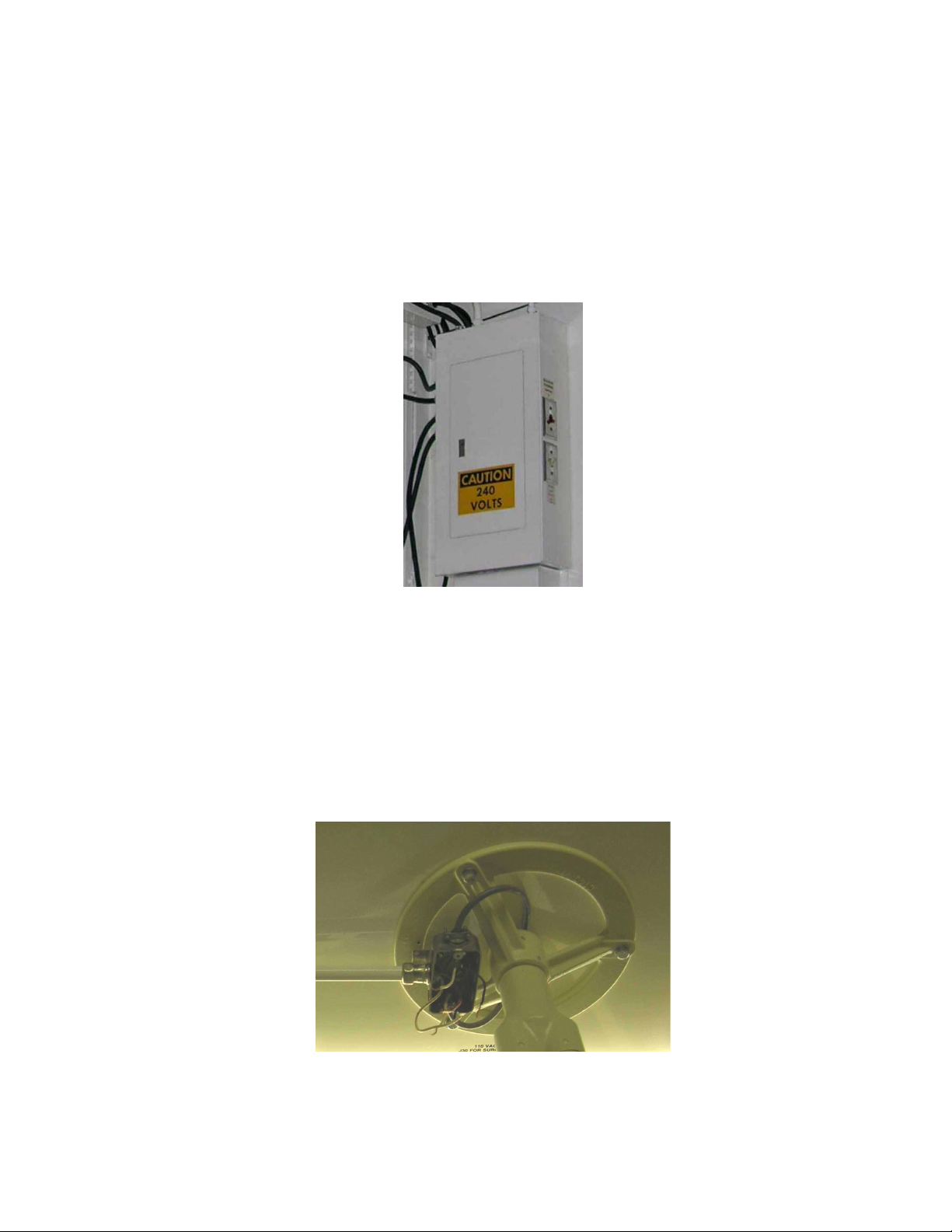
2.1 Disconnect power at main breaker panel
2.1.1 Turn off all power to the lights by turning off the appropriate breaker switches. The breaker
numbers to the lights are listed on the door, inside the breaker panel. See Figure 1.
Figure 1: Power Breaker
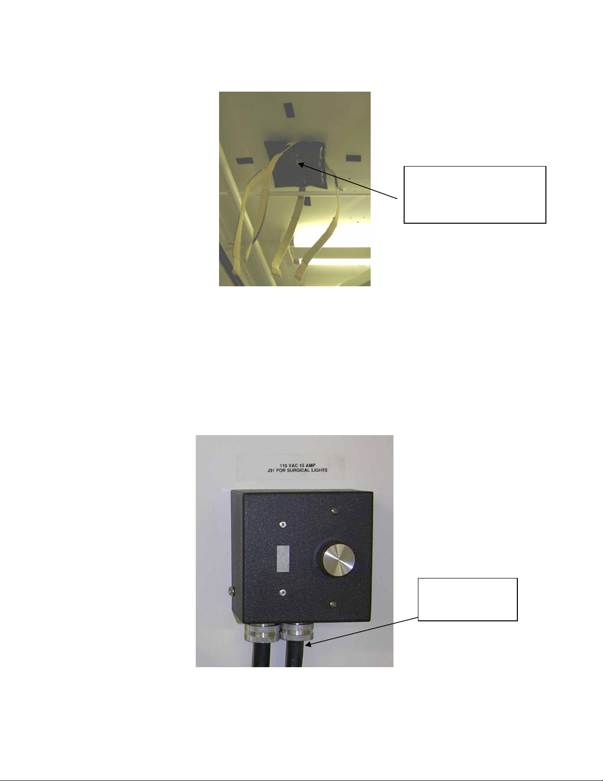
2.2 Remove junction box, conduit and wiring
Remove the junction box cover to access the wires and junction box mounting screws.
Depending on the method used to secure the wires, either twist the wire nuts off, or if
compression wire nuts were used, cut the wires from the wire nuts. After separating the wires,
remove the screws holding the junction box to the ceiling. Next, remove the screws securing
the junction box and conduit from the ceiling channel. Pull the wires through the conduit, but
do not remove them from the ceiling channel at this time. See Figure 2.
Figure 2: Junction Box
4
Blue 80/80 Field Light, Installation, Operators, Service and Parts Manual
HAN40527, Rev A, 21 April, 2006
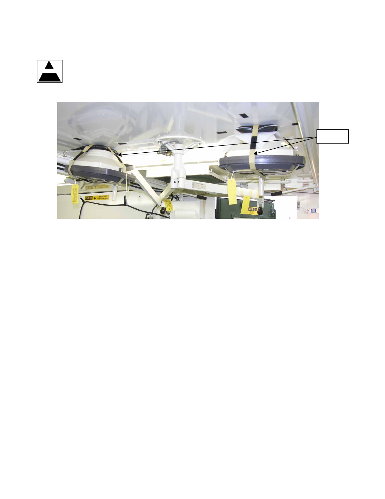
2.3 Remove existing light system
Remove the light heads from the ceiling straps and lower the light heads as far as possible
DANGER
before removing the light system from the ceiling. While one person holds the light system, a
second person shall remove the three bolts securing the lights to the ceiling. Safely lower the
light system to the ground. This is a two-person procedure, and extreme caution should be
used to avoid having the light system drop or fall on someone. See Figure 3.
Straps
Figure 3: Existing Light System
5
Blue 80/80 Field Light, Installation, Operators, Service and Parts Manual
HAN40527, Rev A, 21 April, 2006
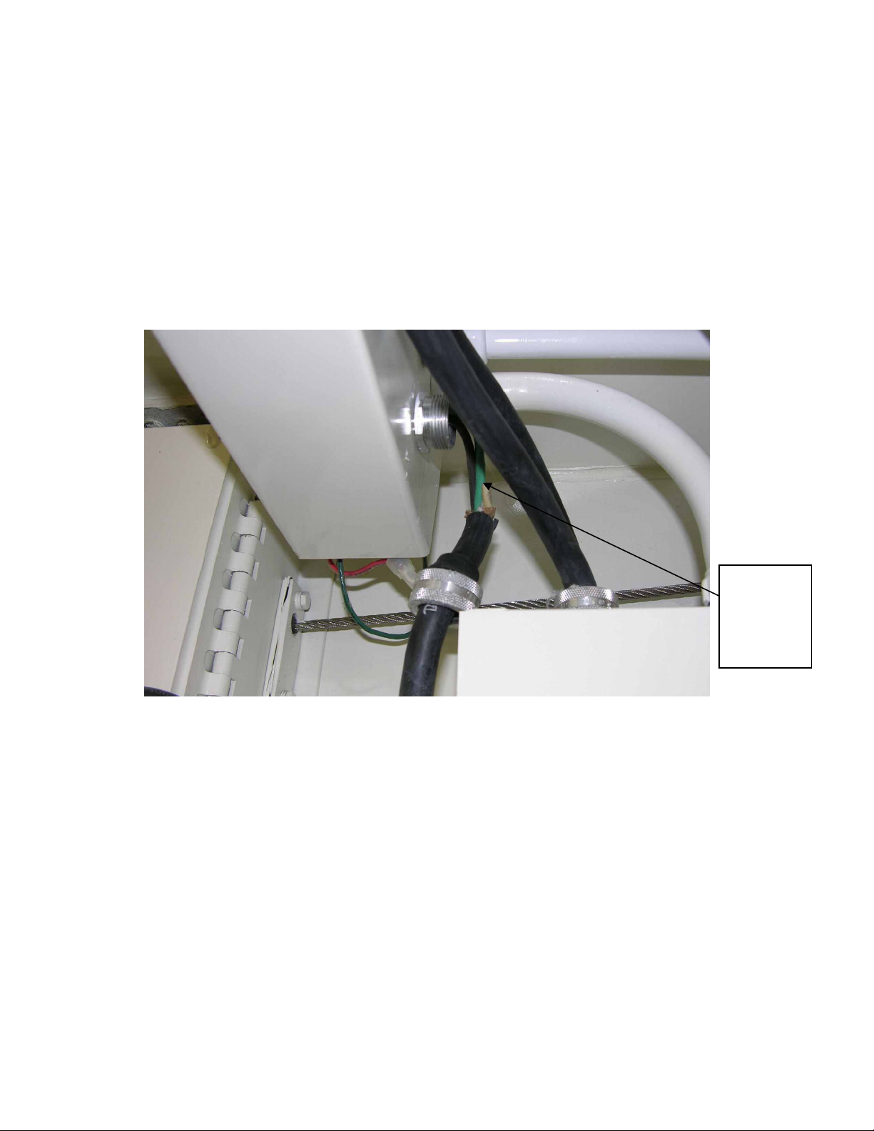
2.4 Remove wires from light system
Remove the strain relief on the far end of the ceiling wire channel located along the middle of
the ISO Shelter ceiling. Pull the cable out approximately 6 inches and cut the Green, White
and Black wires above the black cable insulation. It may be necessary to reach into the end of
the wire channel, and pull the wires out from the end of the wire channel in order to get them
to move freely. At this point do NOT remove the Green ground wire, as it will be used as a pull
wire to run the new wiring through the channel.
Remove the White and Black power wires by pulling one at a time through the opening in the
middle of the channel, or by pulling them out the open end of the channel. It may be necessary
to use needle nose pliers to remove the wires through the strain relief in the middle of the
channel, to get the wire connector through the strain relief, if this option is used. See Figure 4.
Cut wires
here after
removing
cable from
strain relief
Figure 4: Removing Wires from Light System
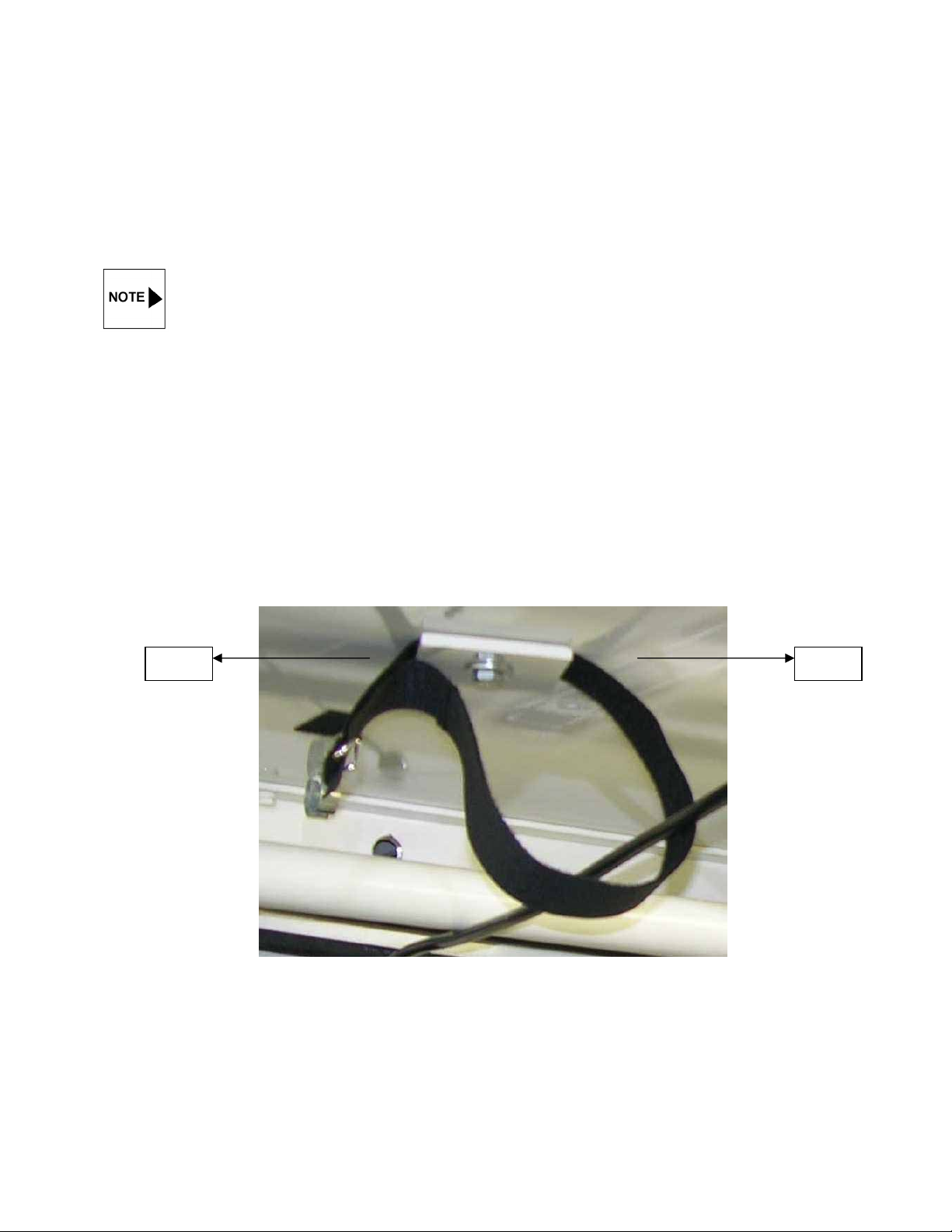
2.5 Remove transportation ceiling pads
Remove the two transportation-ceiling pads with straps that secure the light heads to the
ceiling. Replace the bolt and washer back into the ceiling after removing the straps, as they
will be used later to secure the new arm system transportation straps.
See Figure 5.
6
Blue 80/80 Field Light, Installation, Operators, Service and Parts Manual
HAN40527, Rev A, 21 April, 2006
Figure 5: Removing Transportation Ceiling Pads
2.6 Remove dimmer switch
Unscrew the front cover on the dimmer switch, and cut the three power wires to the cable on
the right hand side. Disconnect the strain relief from the main power feed cable, and pull the
cable out of the box. The strain relief will not be used, and can be discarded. The existing
cable will be used on the new light system. After removing the cable, unscrew the backing
plate from the wall. Remove the strain relief at the ceiling wire channel, and pull the cable and
wires out. The strain relief at the ceiling wire channel will be used later in Step 3.8. See
Figure 6.
After removing the ceiling
pad, reinstall the bolt and
washer into the existing
threaded hole in the ceiling.
The power cable
will be used with
the new light
Figure 6: Remove Dimmer Switch
7
Blue 80/80 Field Light, Installation, Operators, Service and Parts Manual
HAN40527, Rev A, 21 April, 2006
Section 3: Installation of Light Suspension, Wiring and Brackets
This section covers the installation of the Blue 80/80 light system transport system, the main
suspension, wiring, and power supply brackets into the ISO Shelter. This step is performed once
during initial installation of a system.
Before starting the installation, make sure the ISO Shelter is completely level, using the
leveling devices associated with the shelter. If the ISO shelter is not level prior to installation,
the light systems will not hang properly.
3.1 Installation of Ceiling Mounted Transportation Plates and Straps
Unscrew the bolts and washers from the ceiling that were used to secure the ceiling pads in
step 2.3. There are two different length straps, 24" and 40". Mount the 24" closest to the main
cable channel, and the 40" on the other side. If they are mounted with the 40" nearest the
main cable channel, it will have no effect on the operation of the tie down system. Take the
bolt and washer, and slide it through the bottom of the ceiling plate, which is the side without
the groove in it. There is a small hole in the Velcro, approximately 6" from the buckle. Slide the
Velcro strap onto the bolt, with the "fuzzy" loop side facing up, or away from the ceiling plate
surface. The strap will sit in the groove machined into the ceiling plate, and the "fuzzy" loop will
make contact with the ceiling. Secure the ceiling plate to the top of the shelter and tighten, with
the strap running parallel to the ISO shelter (door to door). There are (2) plates per light
system, (4) total. See Figure 7.
Door Door
Figure 7: Installation of Velcro Straps
8
Blue 80/80 Field Light, Installation, Operators, Service and Parts Manual
HAN40527, Rev A, 21 April, 2006
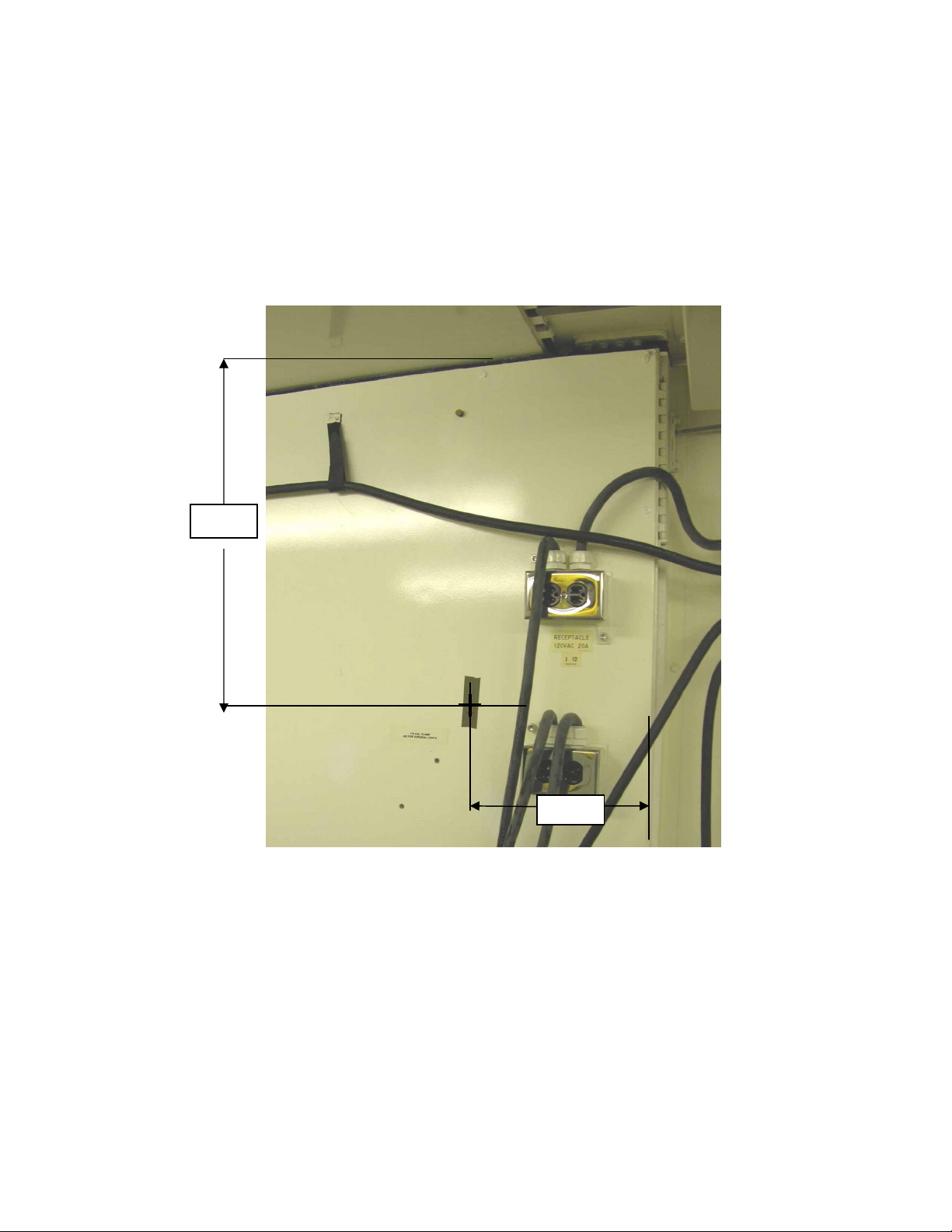
3.2. Power Supply Bracket
3.2.1 Taking a tape measures and a piece of tape, measure down from the ceiling 22 inches,
and from the end of the side wall 11 inches, and place the tape in this area. Go back
and mark and exact centerline location of 22 inches down and 11 inches across onto the
tape. This measurement will be either the top right or top left-hand hole for the drilling
template, depending on which light system is being installed. (right hand shown). See
Figure 8.
22"
11"
Figure 8: Power Supply Bracket Installation
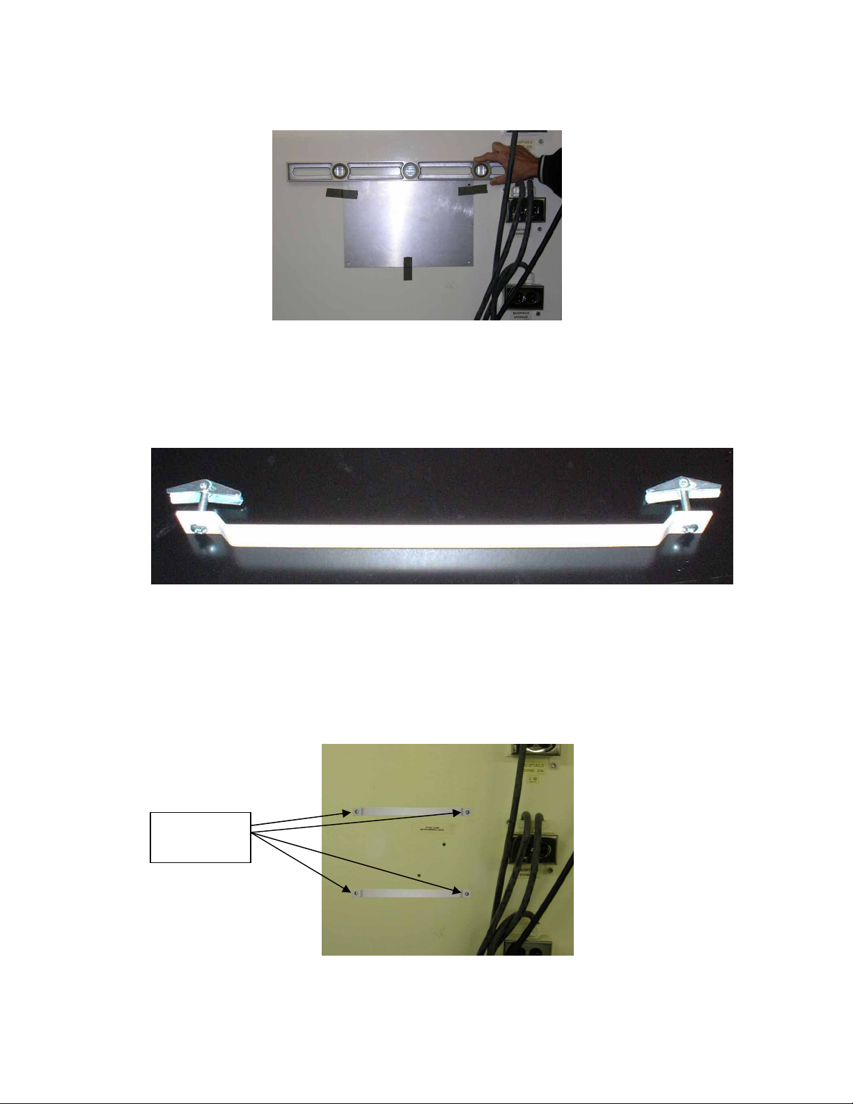
3.2.2 Take the drill template and line up with the marked centerline on the top right or left
hand hole, (depending on which of the two light systems is being installed). Using tape
and a level, line up the template parallel to the floor, and tape the template to the wall.
After the template is installed, mark the four holes onto the wall, and remove the
template. Drill (4) small pilot holes approximately 1/8" to 1/4" in diameter, then finish
using a 5/8" drill bit. See Figure 9.
9
Blue 80/80 Field Light, Installation, Operators, Service and Parts Manual
HAN40527, Rev A, 21 April, 2006
Figure 9: Drilling Template
3.2.3 Take (2) .250-20 x 1 1/2" long threaded bolts, and insert through the Power Supply
Mounting Brackets, and screw on the spring nuts. See Figure 10.
Figure 10: Power Supply Mounting Bracket
3.2.4 It is necessary to leave a very minimum amount of threads securing the spring nut to
the bolt. Push the spring nuts into the holes, and push the bolt and bracket securely
against the wall to enable the spring clip to open. It may be necessary to tighten and
loosen the bolts a few times in order to get the spring clips to engage correctly. If a
spring clip comes loose from the bolt, the spring clip can be removed from the wall
with a pair of needle nose pliers or a similar tool. See Figure 11.
4 Bolts and
Spring Clips
Figure 11: Bolt/Bracket Positioning
10
Blue 80/80 Field Light, Installation, Operators, Service and Parts Manual
acket
and Washers
HAN40527, Rev A, 21 April, 2006
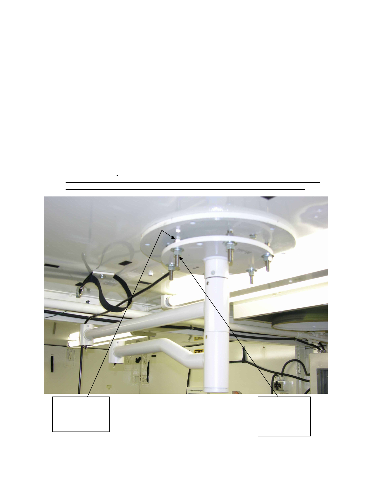
3.3 Ceiling Plate and Flange
Mount the ceiling plate to the ceiling of the ISO shelter using the mounting hardware provided.
The ceiling plate must be aligned so the conduit-mounting bracket is facing the wiring channel.
It will line up directly to the threaded hole in the wiring channel from where the previous
conduit was removed in step 2.2. This is a two-person installation. See Figure 12.
Conduit Mounting
Br
Ceiling plate is heavy, and caution should be taken when installing. Two people
should install this plate, one securing it in position, while the other installs the
hardware.
Figure 12: Ceiling Flange and Plate
(3) Mounting Bolts
11
Blue 80/80 Field Light, Installation, Operators, Service and Parts Manual
HAN40527, Rev A, 21 April, 2006
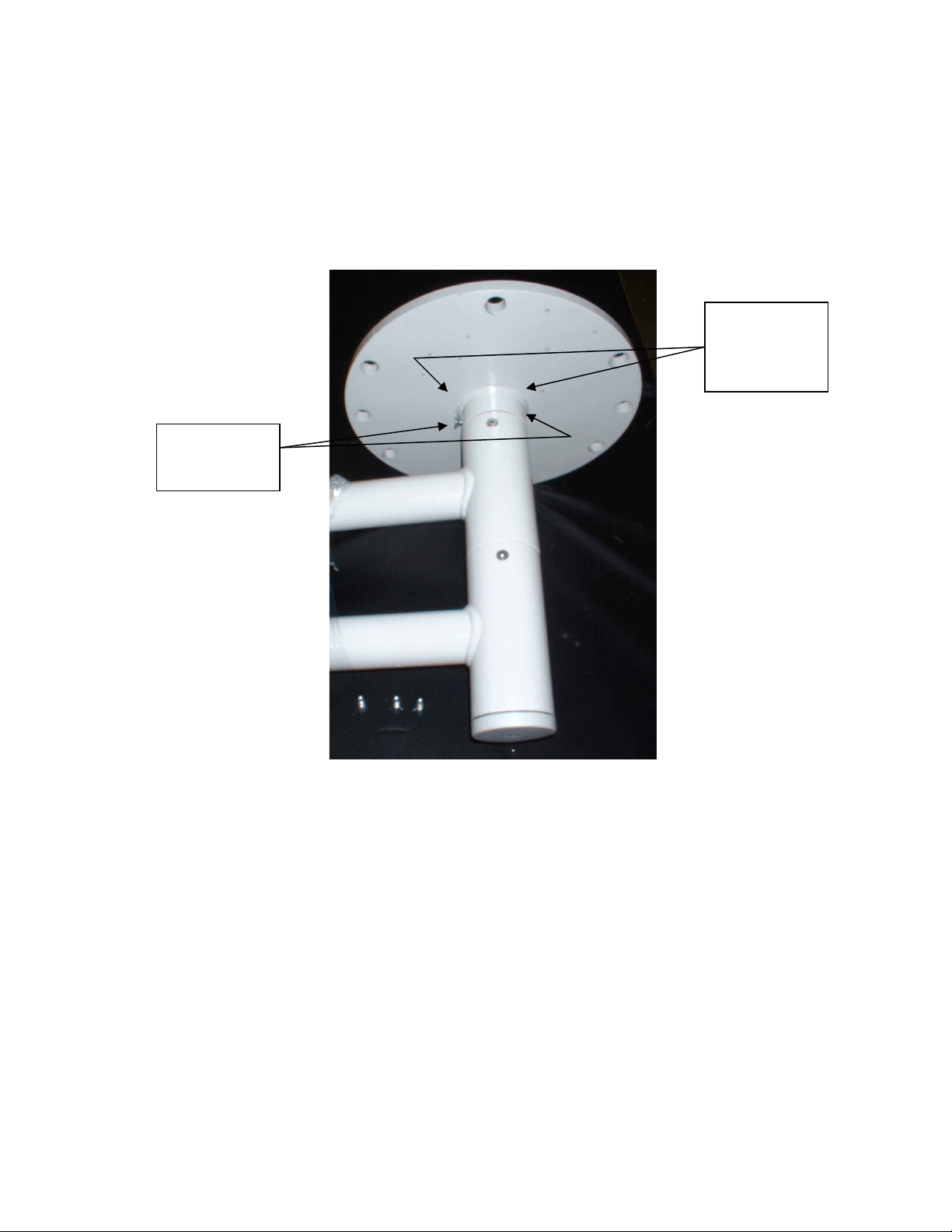
3.4 Ceiling Flange to Main Arm Installation
Slide cable from Main Arm through the throat of the Ceiling Flange. Align the (4) holes, (2)
above and (2) below the circular plate of the ceiling flange, and slide over main arm tube.
Secure to the Main Arm tube with the (4) countersunk screws provided.
See Figure 13.
(2) Screws
below circular
plate
(2) Screws
above circular
plate, (not
shown)
Figure 13: Ceiling Flange and Plate
12
Blue 80/80 Field Light, Installation, Operators, Service and Parts Manual
g
HAN40527, Rev A, 21 April, 2006
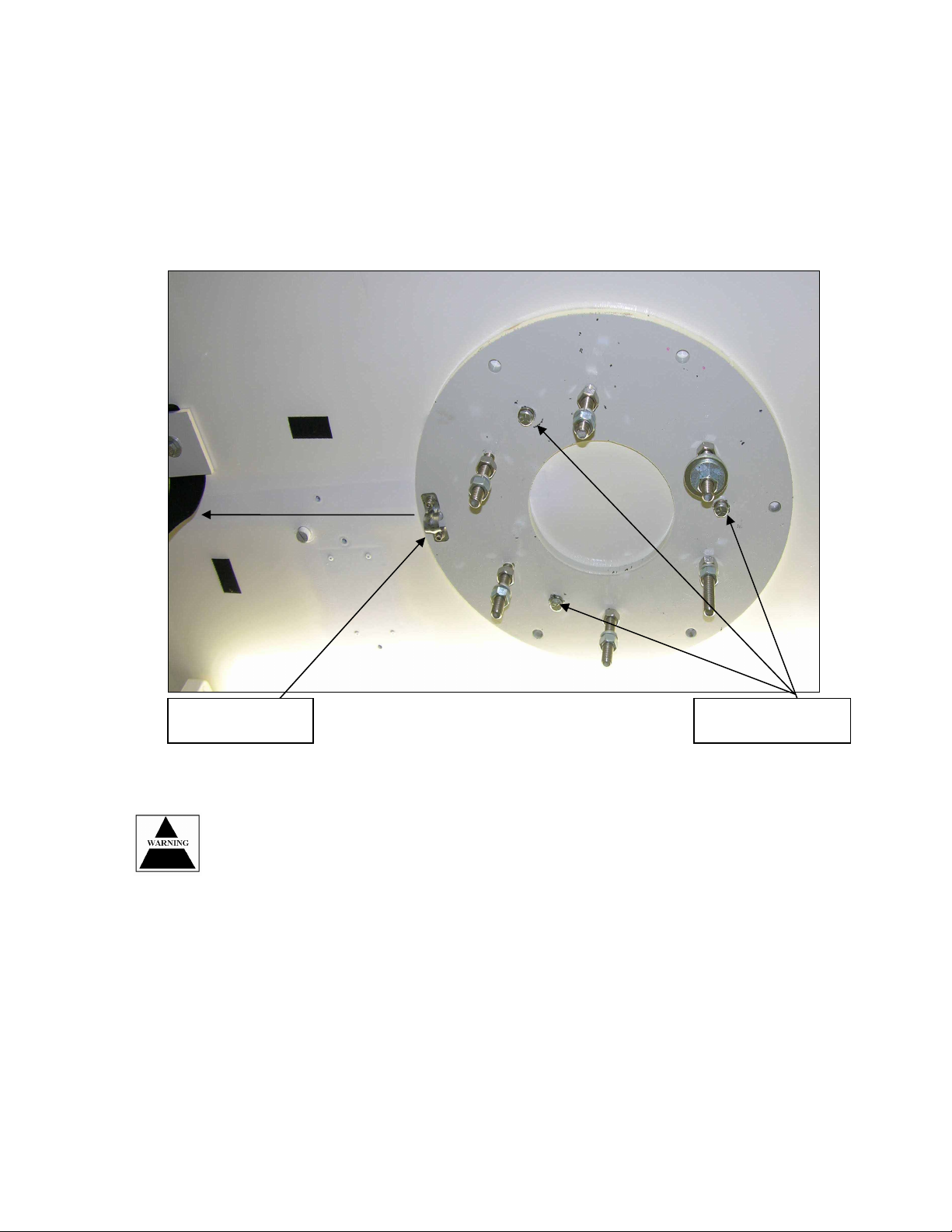
3.5 Main Arm Installation
Before installing the Main Arm, The majority of the hardware on the ceiling plate must be
removed. All that should remain on the (6) studs of the ceiling plate, is (1) hex nut per stud, (6)
total. Screw these (6) nuts all the way flush to the plate. To aid in the installation of the Main
Arm, place (1) flat washer on each stud, and tape it to the ceiling plate. This will allow easier
installation of the Main Arm to the ceiling plate. The Main arm installation is a two person
operation, and the Main Arm must be aligned correctly before attaching any further mounting
hardware. There is a small notch machined out of the top of the Main Arm tube that must run
parallel to the conduit-mounting bracket. This notch is for the cable to sit in when the Main Arm
is tightened to the ceiling plate. Once the Main Arm is aligned with the notch, secure the Main
arm to the (6) studs using a flat washer, a lock washer and a hex nut on each stud. Slowly
tighten the lower nuts, but do not tighten them completely. Make sure the cable is still sitting in
the notched cutout while tightening the nuts. Once the upper tube of the Ceiling Flange is
almost touching the Ceiling Plate, take the small bubble level supplied with the installation kit,
and adjust the lower nuts until the Ceiling flange is sitting level on the studs. At this time,
tighten the upper nuts down onto the Ceiling Flange, checking afterwards to make sure the
Flange is still level.
NOTE: If Spring Arms are to be installed on Main Arm before mounting Main Arm to
ceiling flange, follow Steps 3.10.1 and 3.10.2 first, then install unit as shown above.
See Figure 14.
(1) Nut
(1) flat washer
per stud above
ceiling flange
Figure 14: Main Arm Installation
(1) Nut
(1) lock washer
(1) flat washer
per stud below
ceilin
flange
13
Blue 80/80 Field Light, Installation, Operators, Service and Parts Manual
HAN40527, Rev A, 21 April, 2006
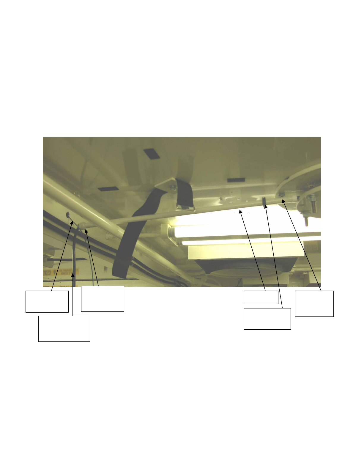
3.6 Main Arm Wiring and Conduit Installation
Take the small black grommet from the ceiling cover, and slide it over the conduit. Next, take
the power cable from the Main Arm and slide it through the cut end of the conduit, exiting the
end with the compression fitting. Take the end of the cable and tape it to the existing green
lead wire exiting the middle of the ceiling wiring channel from the old light system. Slowly pull
the green wire through the wiring channel at the far end of the channel. After the wire has
successfully been pulled through the end of the wiring channel, screw the conduit into the
existing threaded hole in the wiring channel and tighten. Next, secure the opposite end of the
conduit under the conduit-mounting flange located on the Ceiling Plate and tighten. See Figure
15.
Existing
green wire
Main arm cable
taped to green
wire
Conduit
compression
fitting
Figure 15: Conduit Installation
Conduit
Ceiling cover
grommet
Conduit
mounting
flange
14
Blue 80/80 Field Light, Installation, Operators, Service and Parts Manual
HAN40527, Rev A, 21 April, 2006
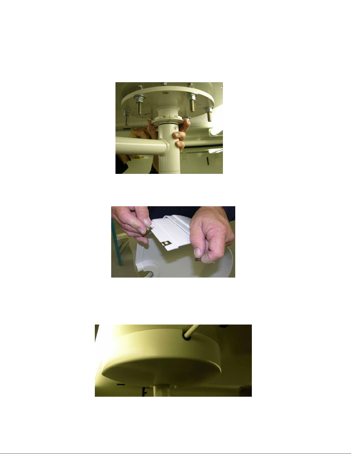
3.7 Ceiling Cover Installation
3.7.1 Around the main axle, you must now mount the retaining brackets. This is done by
clamping the two brackets around the axle, screw side out. Tighten Screws. See Figure
16.
Figure 16: Retaining Ring Assembly
3.7.2 Place the clamps onto the hood assembly as shown in Figure 17.
3.7.3 Place both hood pieces around the main shaft, inserting the bottom of hood into the
groove from the small retaining ring. Ensure that rubber grommet around conduit fits
snugly inside of hood. Screw hood assembly to plate assembly. See Figure 18.
Figure 17: Retaining Clamps, Hood Assembly
Figure 18: Assembled Hood Assembly
15
Blue 80/80 Field Light, Installation, Operators, Service and Parts Manual
cable
HAN40527, Rev A, 21 April, 2006
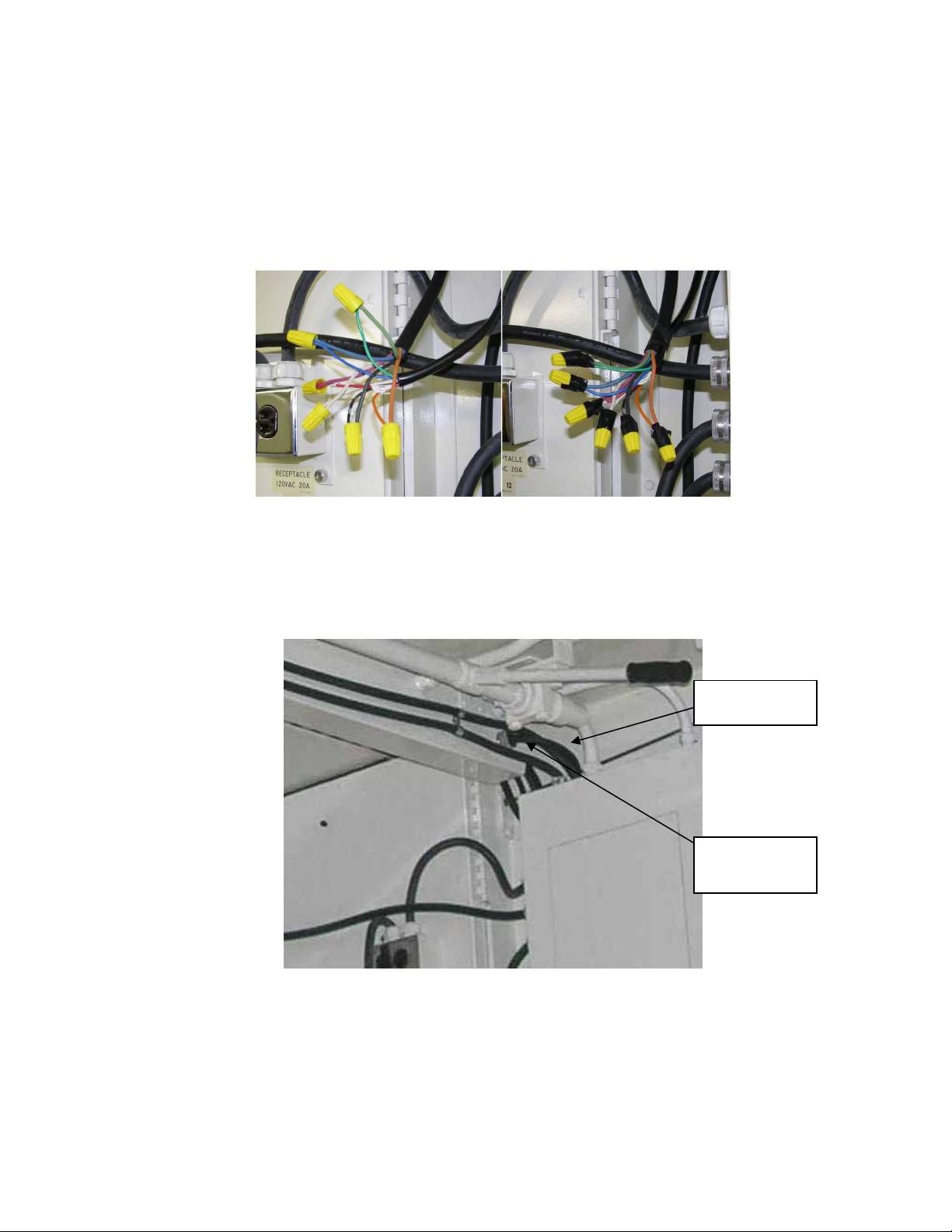
3.8 Low Voltage AC Wire Run from Power Supply to Light Connection
3.8.1 Place the existing strain relief black rubber grommet (from Step 2.6) and nut over the 6
wire, 5 foot long, "AC out" cable end, leaving approximately 12" to 16" of cable. Place the
cable through the side of the wiring channel and pull the wires through the open end of the
channel. Take the 6-wire cable from the light system, and match the 6 wires from the AC
out cable, and secure together using the wire twist nuts provided. After securing the wires
together with the wire nuts, take the black electrical tape supplied and wrap the wire nuts
and wires securely together. See Figure 19.
Figure 19: Low Voltage AC Connections
3.8.2 Push the taped wire/cable bundle into the open end of the wiring channel, slowly pulling
the "AC out" cable through the strain relief in the wire channel. After successfully placing
the taped ends of the cables back into the open end of the wiring channel, secure the
"AC out cable to the wiring channel with the strain relief grommet and nut. See Figure 20.
5' "AC OUT"
Compression
fitting
Figure 20: AC OUT Cable Route
16

Blue 80/80 Field Light, Installation, Operators, Service and Parts Manual
HAN40527, Rev A, 21 April, 2006
3.9 High Voltage AC Wire from Power Source to Power Supply
Take the female 20-amp connector and remove the rubber back, which will expose the two
cable clamping screws. Slide the rubber backing over the existing power cable that was cut
from the dimmer switch box. Slide the connector body over the cable. Splice the (3) wires from
the cable approximately 1 1/2" to 2 1/2" long, and strip the ends of the wires approximately
1/4" to 1/2" long. Secure the Green wire to the position marked "W", The Black wire to the
position marked "X" and the White wire to the position marked "Y". After securing the wires to
the connector, push the cable into it's housing, and secure the two-connector pieces together
with the (3) screws on the top of the connector. Next, pull the cable tight and secure the cable
to the connector by tightening the two sides screws. Slide the rubber back piece onto the back
of the connector, until it snaps into place. See Figure 21.
Figure 21: High Voltage AC Wire/Plug
17

Blue 80/80 Field Light, Installation, Operators, Service and Parts Manual
connecto
ole
HAN40527, Rev A, 21 April, 2006
3.10 Spring Arm to Main Arm Installation
3.10.1 Unscrew the (2) screws securing the cover to the top of the Main Arm, and pull the
connector out of the Main Arm before proceeding. The Spring Arm must first be locked into
a downward position before installing. Slide the Spring Arm into the Main Arm and align
and insert the retaining pin provided with the arm, into the retaining pin hole as shown,
while holding the spring arm in the down position. This is a two-person installation. One
person should hold the Spring Arm firmly in place, while the other inserts the pin, to avoid
any injury.
Use caution when installing the Spring Arm. It is under extreme spring tension,
and can cause serious injury if it slips out of your hand and springs upward. Avoid
leaning your head over the Spring Arm during installation, and have someone help
hold the Spring Arm in position while inserting the retaining pin. See Figure 22.
Retaining pin
Retaining pin
h
Figure 22: Spring Arm to Main Arm Install
Male
r
18

Blue 80/80 Field Light, Installation, Operators, Service and Parts Manual
HAN40527, Rev A, 21 April, 2006
3.10.2
Insert the Spring Arm into the Main Arm and install the two screws provided with the arm,
and gently tighten in place. Push the Male connector at the top of the Main Arm into the
Female connector of the Spring Arm and reinstall the (2) screws securing the cover and
connector into place in the Main Arm. Do not remove retaining pin in Spring Arm at this
point. It will be removed after the light head has been installed. See Figure 23.
Figure 23: Inserting Male Light Plug
19

Blue 80/80 Field Light, Installation, Operators, Service and Parts Manual
HAN40527, Rev A, 21 April, 2006
Section 4.0: Installation of Lampheads and Power Supply:
This section covers the repeated installation of the lampheads and power supply into the ISO
shelter.
Section 4.0 of this manual will be repeated every time the ISO shelter is assembled.
4.1 Removing Components from shipping case.
4.1.1 Verify correct shipping container by referring to label on side of container. See Figure 24
Figure 24: BLUEMMSA Container Label
4.1.2 Unfasten the 16 quick twist connect fasteners from around the shipping container.
20

Blue 80/80 Field Light, Installation, Operators, Service and Parts Manual
HAN40527, Rev A, 21 April, 2006
4.1.3 Open container and verify that the following items shown in Figure 25 are present.
• (1) HAN40489 Maquet Power Supply(s)
• (2) 5607-7852 Blue 80 Lampheads
• (2) 5605-3026 Spare Light Bulbs
• (3) 5606-0756 Sterile Handles
• (1) HAN40580 Bubble Level
• (1) HAN40527 Manual, Blue 8080 Field Light Rev A
Figure 25: Blue 80 Light Container Inventory
4.1.4 All parts shall be stored as shown in Figure 25 above, when system is packed for
shipment.
21

Blue 80/80 Field Light, Installation, Operators, Service and Parts Manual
HAN40527, Rev A, 21 April, 2006
4.2 Lamphead Installation
Use care when pulling the connector out using needle nose pliers. This can damage
the connector if squeezed too much via the pliers, or deformed by using too much
force. If any resistance is encountered when pulling the connector out, stop pulling
and check for obstructions.
4.2.1 If the mating connector is located inside the tube of the Spring Arm end, carefully pull
it out using a pair of needle nose pliers. If the connector is outside the arm, bypass
this step. See Figure 26.
Figure 26: Lamphead Installation
22

Blue 80/80 Field Light, Installation, Operators, Service and Parts Manual
HAN40527, Rev A, 21 April, 2006
4.2.2 Remove the Blue 80 Lamphead from its protective shipping container. Connect the
mating connectors from the Spring Arm and Blue 80 Lamphead together. Make sure
the connectors are securely fastened before proceeding.
See Figure 27.
Figure 27: Spring Arm Connection
4.2.3 Slide the Blue 80 Lamphead into the Spring Arm, aligning the mounting hole. Secure
the Lamphead onto the spring arm using the socket head cap screw provided and
tighten. See Figure 28.
Figure 28: Securing Lamphead
23

Blue 80/80 Field Light, Installation, Operators, Service and Parts Manual
HAN40527, Rev A, 21 April, 2006
4.2.4 Remove the retaining pin from the side of the Spring Arm and snap the protective
cover onto the end of the spring arm. Place the retaining pin in the lamphead
transportation box for future use. See Figure 29.
Remove
retaining pin
Figure 29: Retaining Ring/Protective Cover
Install protective
end cover
24

Blue 80/80 Field Light, Installation, Operators, Service and Parts Manual
HAN40527, Rev A, 21 April, 2006
4.3 Power Supply Installation and Connection
Remove the Power Supply from its shipping container. Lift the Power supply onto the wall
brackets next to the breaker panel. Connect the AC power to the "AC IN" connector located on
the bottom right hand side of the Power supply. Connect the Lamphead power supply cable to
the "AC OUT" connector located on the bottom middle section of the power supply. Both
connections are labeled accordingly on the front of the Power Supply enclosure. See Figure 30.
The Power Supply is extremely heavy, and care should be taken to avoid dropping it.
It is highly recommended to have two persons lift the Power Supply into place.
Power
supply
"AC IN"
power cable
"AC OUT"
cable to
lamphead
Figure 30: Military Power Supply
Mounting
brackets
25

Blue 80/80 Field Light, Installation, Operators, Service and Parts Manual
HAN40527, Rev A, 21 April, 2006
4.4 Setting Power Supply Taps
The taps to select are dependent upon the incoming voltage at the primary winding. Both the
primary and secondary taps may need to be changed to obtain the optimal voltage across the
bulb at the lamphead. See Figure 31 for Tap locations.
Primary tap
locations on
transformers
Secondary tap
H4
DONGA
CATALOG NSC-29H9PRI.
SEC.
PHASE
HERTZ
KVA
SERIAL
locations on
transformers
LOW ER
LIGHT
TRANSFORMER
H3
IN DU ST RIA L
TRANSFORM
110/115/12
24....2
SINGL
60
.500
P0312
X6X8 X7 X5 X4 X3 X1
H2 H1
ENCL
INS .
INS .
TEM P.
Figure 31: Primary/Secondary Taps
U
L
LISTED
SA
C
LR56
416180
55 C
TRANSFORMER
H4
DONGA
CATALOG NSC-29H9PRI.
SEC.
PHASE
HERTZ
KVA
SERIAL
H3
INDUSTRIAL
TRA NS FOR M
110/115/12
24....2
SINGL
60
.500
P0312
X6X8 X7 X5 X4 X3 X1
UPPER
LIGHT
ENCL
IN S.
IN S.
TEM P.
H2 H1
U
L
LISTED
SA
C
LR56
416180
55 C
26

Blue 80/80 Field Light, Installation, Operators, Service and Parts Manual
HAN40527, Rev A, 21 April, 2006
4.5 Initial Setting of Power Supply Voltages
4.5.1. Table 2 provides recommended secondary tap positions based upon using input taps
H1-H4. The secondary voltages are set to achieve the approximate 21.4vac across the
lampheads bulb.
Primary
Voltage
Primary AC
Input Tap
Recommended
Output Tap
Approximate
Voltage at Light
110vac H1 and H4 X1 and X8 21.32vac
111vac H1 and H4 X1 and X8 21.50vac
112vac H1 and H4 X1 and X7 21.31vac
113vac H1 and H4 X1 and X7 21.55vac
114vac H1 and H4 X1 and X6 21.38vac
115vac H1 and H4 X1 and X6 21.55vac
116vac H1 and H4 X1 and X5 21.28vac
117vac H1 and H4 X1 and X5 21.50vac
118vac H1 and H4 X1 and X4 21.35vac
119vac H1 and H4 X1 and X4 21.48vac
120vac H1 and H4 X1 and X3 21.20vac
121vac H1 and H4 X1 and X3 21.40vac
122vac H1 and H4 X1 and X3 21.58vac
123vac H1 and H4 X1 and X2 21.31vac
124vac H1 and H4 X1 and X2 21.46vac
125vac H1 and H4 X1 and X2 21.66vac
Table 3: Transformer Tap Voltages
4.5.2. To measure the voltage across the bulb, you must use a standard multimeter
set at VAC. Access the light panel on rear of Blue 80 light head. See Figure 32
Figure 32: Blue 80 Bulb Access Panel
27

Blue 80/80 Field Light, Installation, Operators, Service and Parts Manual
HAN40527, Rev A, 21 April, 2006
Precaution will be taken while measuring voltage in rear of light panel. Possibility
of shock and/or burns could occur while performing this procedure.
4.5.3 Insert multimeter leads as shown into rear of bulb that is designated by the
letter “R”. This is the main bulb; the other bulb is backup and only illuminates
when the main bulb is burnt out. See Figure 33
Figure 33: Blue 80 Voltage Measurement
4.5.4 Adjust the secondary taps shown in Chapter 5.3, Figure 28, to achieve 21.5 VAC,
+ - ½ volt across the bulb.
4.5.5 After properly checking and setting the voltage at both lampheads and transformers, the
system can be placed into operation.
28

Blue 80/80 Field Light, Installation, Operators, Service and Parts Manual
HAN40527, Rev A, 21 April, 2006
Section 5: Securing Blue 80 Main Arms
5.1 Removal of Blue 80 lampheads and Maquet power supply
5.1.1 Secure all power to Blue 80 Lamp System by disconnecting main power from the
Maquet power supply.
5.1.2 Remove the lampheads from main arm. NOTE: Ensure the stop pin is in main
arm as described in step 3.10.1.
5.1.3 Place lamphead(s) within shipping container as shown in Figure 25.
5.1.4 Remove all cabling (2) from Maquet power supply. Remove power supply from wall
mount and store in shipping container as shown in Figure 25.
5.2 Securing main arm and spring arms
5.2.1 Place Velcro Strap P/N HAN40475 on main arm as shown in Figure 34.
Figure 34: Velcro Strap, P/N HAN40475
29

Blue 80/80 Field Light, Installation, Operators, Service and Parts Manual
HAN40527, Rev A, 21 April, 2006
5.2.2 Rotate spring arm towards main axle and place both Velcro straps around arm as
shown in Figure 35.
Figure 35: Spring Arm strapping position
5.2.3 The final strap will be placed around the main arm as shown in shown in Figure 36.
Figure 36: Ceiling Mounted Velcro Strap, P/N HAN40468
5.2.4 Repeat procedure for the second main arm unit. When complete, system is ready
for shipment.
30

Blue 80/80 Field Light, Installation, Operators, Service and Parts Manual
HAN40527, Rev A, 21 April, 2006
Section 6.0: Operation of the Blue 80/80 Light System:
6.1 Setting up Light source
6.1.1 The Blue 80 Light head is designed to operate in the ranges of 27.5 – 51 inches. This will
allow the light to apply the 80,000-lux over the operation field in an even field of light. To
view the light wave pattern, refer to the below picture. See Figure 37.
Figure 37: Blue 80 Lamphead
6.1.2 The dual Blue 80 light sources allows a total of 160,000 lux (80,000 lux each lamp head) to
be used on the patch area from a wide variety of angles. This light arm was designed with
the ergonomics of the ISO shelter in mind and is small and compact in nature. To move
the light heads where needed, simply place a sterilizable Handle onto light attachment and
adjust according to doctor’s field of view needs. See Figure 38.
Figure 38: Lamphead Alignment
31

Blue 80/80 Field Light, Installation, Operators, Service and Parts Manual
HAN40527, Rev A, 21 April, 2006
6.2 Energizing the Power Supply.
6.2.1 The power supply has two front panel mounted breaker switches, each controlling the
voltage for the upper or lower light assembly. Once the power supply is attached via its
main AC IN and AC out power cables, the unit is ready for operation. The breakers are
individually labeled and by depressing the rocker switches, a green light will illuminate
showing the transformers inside the power supply are connected to 120VAC power. See
Figure 39.
Figure 39: Blue 80/80 Power Supply
32

Blue 80/80 Field Light, Installation, Operators, Service and Parts Manual
HAN40527, Rev A, 21 April, 2006
Section 7.0: Preventive Maintenance of Blue 80/80 Light System
DANGER OF BURNS
before starting any PMs
DANGER
DANGER OF INJURY:
head, Arm is under great pressure and severe injuries will
occur.
DANGER OF BODILY HARM:
7.1 Preventative maintenance is recommended to keep the lights operational when required.
Maintenance Task When Performed Details
Power Supply Mounting
Bracket Check
Illumination (Lux) Verification Every 6 months
: The lighthead heats up during operation. Allow cooling off
ENSURE Spring Arms are restrained when removing light
Disconnect the Power supply from the mains and make it
voltage-free before starting any repair work
Check fasteners to ensure that the
Prior to every installation
brackets are tight and secured to the
wall.
Using a lux meter, check for proper
output = 80,000 Lux measured at 39
inches from lamphead, with 7.1-inch
circular pattern.
Lamphead inspection Every 6 months Replace according to Chapter 8.5
Spring Arm Tension Adjustment
Every 3 months or as
necessary
Adjust according to Chapter 8.3
Table 4: Preventative Maintenance Recommendations
7.2 Inspection by the Operator
The Blue 80/80 light heads and supporting structure is to be inspected by the operator every six
months, with particular attention to the following points:
• Defects in point work
• Cracks in plastic parts
• Deformation in the supporting system
33

Blue 80/80 Field Light, Installation, Operators, Service and Parts Manual
HAN40527, Rev A, 21 April, 2006
7.3 Cleaning/Disinfection
To avoid damage to plastic and glass parts, do not use any scouring agent, or
any cleaning agent which is alkaline, acidic or contains alcohol (e.g. ethanol,
propanal or aldehyde).
• Only disinfect the apparatus when it is cold
• We recommend our tested cleaning/disinfection agent HANAU-clean
• Because there are a great number of cleaning/disinfecting agents on the market, and we do
not know their interactions with plastic used, damage cannot be ruled out if other agents
are used.
• For cleaning, use a soft, lint-free cloth
7.4 Sterilizing the handles
Please immediately replace all damaged Handles showing cracks or
deformations because these could fall down into the wound.
• Push in the spherical catch of the Handle and pull Handle off downwards
• Push the Handle back on until you hear the catch click, check for proper seat.
• Place the Handles standing upright and with the open side facing down
• Do not exceed a sterilization temperature of 134 degrees Celsius
• Avoid letting the Handles come into contact with other objects while they are being
sterilized.
34

Blue 80/80 Field Light, Installation, Operators, Service and Parts Manual
HAN40527, Rev A, 21 April, 2006
Section 8.0: Corrective Maintenance
DANGER OF BURNS: The lighthead heats up during operation. Allow cooling off
DANGER
8.1 Troubleshooting procedures
Table 5 provides a quick reference for troubleshooting the Blue 80/80 system.
before starting any repair work
DANGER OF INJURY:
DANGER OF BODILY HARM:
ENSURE Spring Arms are retrained when removing light head,
Arm is under great pressure and severe injuries will occur.
Disconnect the Power supply from the mains and make
it voltage-free before starting any repair work
Table 5: Mechanical/Optical Troubleshooting
35

Blue 80/80 Field Light, Installation, Operators, Service and Parts Manual
HAN40527, Rev A, 21 April, 2006
8.2 Lighthead removal procedures
8.2.1 Remove lid (1) from the movable side of the weight balancer (2). See Figure 40.
8.2.2 Swing the weight balancer towards the floor and insert retaining pin (3) into drill hole (4).
See Figure 40.
Figure 40: Weight Balancer
Failure to insert the retaining pin far enough into the drill hole may cause the
weight balancer to bounce up and cause injuries. Check that the weight balancer
is firmly locked into position before you let go.
8.2.3 Unscrew hexagon socket screw (1). Unscrew brake screw (2). See Figure 41.
8.2.4 Pull off Handle (3) off weight balancer and disconnect the plug connection (4). See
Figure 41.
Figure 41: Blue 80 lighthead brake screw
36

Blue 80/80 Field Light, Installation, Operators, Service and Parts Manual
HAN40527, Rev A, 21 April, 2006
8.3 Spring arm tension adjustment procedure
8.3.1 Remove the lid of moveable weight balancer arm (1) and also, on the Blue 80-weight
balancer, the lid of fixed weight balancer arm (2). See Figure 42
8.3.2 Turn adjustment nut (3) by half a turn maximum: make sure to hold the hexagon socket
screw on the other side of the Blue 80-weight balancer. See Figure 42.
Figure 42: Spring arm brake adjustment
8.3.3. Turn clockwise if the light head sinks down or turn counter clockwise if the light head moves
up.
8.3.4 Check whether the light balancer stops moving in every position. Continue adjusting until
arm no longer moves from desired position.
8.3.5 Put the lid back on weight balancer.
8.4 Setting the brake pressure of the Blue 80 lighthead
CAUTION HIGH TEMPERTURE: The light heads heat up during operation. Make sure
to let the light head cool off before you set the brake pressure.
8.4.1 Let the light head cool off. Set the brake pressure of the light head by tightening or
loosening brake pressure adjustment screw (1) underneath light head Handle (2). See
Figure 43.
Figure 43: Blue 80 Lighthead brake adjust
37

Blue 80/80 Field Light, Installation, Operators, Service and Parts Manual
HAN40527, Rev A, 21 April, 2006
8.5 Replacement of bulbs
Please note to use replacement bulbs supplied by Getinge to reach the safe function and
the technical lighting data. DO NOT touch the glass body of the halogen bulb with bare
fingers. When the yellow signal lights up at the lower side of lighthead, this indicates
that the reserve bulb has taken over operation. To avoid a complete failure of the
lighting system, please replace the main bulb as soon as possible. The position of the
main lamp is indicated by a dot on the reflector shield.
8.5.1 Slightly push in lid (1) on the hood (2) and push to one side. See Figure 44
8.5.2 Take out socket (5) towards to the top.
Figure 44: Light bulb replacement procedure
8.5.3 Remove broken halogen bulb (3) from the side of the connection lead.
8.5.4 Remove spare lamp (4) marked with “R” and put into the socket of the main lamp.
8.5.5 Put in new bulb into the socket of the spare lamp.
8.5.6 Put both lamps back into the reflector in a way that the marked position “R” on the
reflector and the socket is opposite. Put lid back on and check the lid for safe seating.
38

Blue 80/80 Field Light, Installation, Operators, Service and Parts Manual
HAN40527, Rev A, 21 April, 2006
Section 9. Troubleshooting the Power Supply
The following is a list of probable faults and their associated corrective action. Observe all
safety precautions when working on this unit. See Table 6 for Troubleshooting Guide and
Figure 45: Schematic, Wiring, Power Supply, Military.
Failure Probable Cause Corrective Action
- Reset main breaker
Unit does not
energize
• Main Breaker
• Main AC IN Connector
• H1 or H4 Terminals (Primary)
• AC wires loose (inside)
- Disconnect and reset AC IN Connector
- Check voltage at H1/H4, Possible bad
Primary Transformer. Order and replace.
- Check for loose wires, retighten as
necessary
Upper and/or Lower
Light will not
energize
Breaker indicator on,
but light not working
Light bulbs burning
out too quickly
Front panel ON light
indicators not
working
• Front panel breaker(s)
• Light bulb(s)
• Loose wire on front breakers
• Transformer secondary fuse
• Light bulb(s)
• AC OUT Connector
• AC OUT Connections
• Incorrect secondary voltage
settings
• Bad ground on breaker
• Blown LED indicator
Table 6: Power Supply Troubleshooting
- See if light indicator is on. If not, reset
breaker
- Replace bulb(s)
- Reterminate wires on breaker assembly
- Replace 9 amp secondary fuse(s)
- Replace light bulb(s)
- Reset AC Out Connector
- Check for broken wires on AC OUT
Connector
- Adjust secondary voltages by moving X2-X8
to set voltage to 21.4vac as read at light
head
- Check Red and Black 28 AWG wires on
secondary of breaker. Reterminate wires.
- Replace 20 Amp breaker assembly
39

Blue 80/80 Field Light, Installation, Operators, Service and Parts Manual
HAN40527, Rev A, 21 April, 2006
Figure 45: Schematic, Wiring, Power Supply, Military
40

Blue 80/80 Field Light, Installation, Operators, Service and Parts Manual
HAN40527, Rev A, 21 April, 2006
Section 10.0: Parts Listing
10.1 Table 7 provides upper level part numbers for Blue 80 system components.
Ceiling Flange
1
Item PART NUMBER PART NAME FIGURE
1 569004905 Ceiling Flange Figure 46
2 569004990 Suspension, Duo, Blue 80 Figure 46
3 569004991 Spring Arms Figure 47
4 5607-7852 Blue 80 Lightheads Figure 47
5 BLUE80/80CASE Blue 80 Shipping Container Figure 24
Table 7, Upper level system part numbers/components
Duo 80 Suspension
2
Spring Arm (2)
3
Blue 80 Lampheads
4
Figure 46: Flange and Suspension
Figure 47: Spring Arms and Lightheads
41

Blue 80/80 Field Light, Installation, Operators, Service and Parts Manual
HAN40527, Rev A, 21 April, 2006
10.2 Blue 80 Lighthead Parts
10.2.1 Figure 48 below, designates part numbers for Blue 80 lighthead, Part number
5607-7852. For individual component breakdown, refer to Table 7.
1
6
7
8
9
2
10
3
11
4
5
12
13
14
Figure 48: Blue 80 Light Components
Item Part number Part description
1 5605-3016 Blue switch 1 pole 250 v 10 a
2 5605-3083 Blue80, Handle-adapter
3 5605-0756 Handle; plastic ;2000 series; pkg. (3)
4 5605-3071 Assy PCB. b80 light head
5 5605-3067 Blue 80 disc, glass
6 5605-3069 Blue 80 with leaf spring
7 5605-3026 Bulb; B80 21.5v; 130 w
8 5605-3073 Blue 80 bulb sockets
9 5605-3256 Blue 80 bulb wire
10 5605-3070 Cover
11 5605-3154 Assy, dome cap cover lighthead
12 5605-3074 Blue 80 wiring complete
13 5605-3068 Blue 80 reflector
14 5605-3271 Blue 80 reflector f.
Table 8: Blue 80 Part Number/Descriptions
42

Blue 80/80 Field Light, Installation, Operators, Service and Parts Manual
HAN40527, Rev A, 21 April, 2006
10.3 ISO Shelter Mounting Kit
10.3.1 Table 9 provides the parts contained in the ISO Mounting Kit, Part Number
HAN40525. The individual part drawings follow.
Figure Part number Part description
49 HAN40457 Assy, conduit, 1/2" emt
50 HAN40460 Assy, ring, anchor plate
51 HAN40464 Toggle, spring wing
52 HAN40465 Screw, rh, ph,.250-20, unc3a,
53 HAN40466 Plate, holding, velcro
54 HAN40467 Template, mtg, xfmr box, army
55 HAN40468-24 Strap, velcro, 2" x 24"
55 HAN40468-40 Strap, velcro, 2" x 40"
56 HAN40475 Cover, transport, arm
57 HAN40482 Conn., Turn lock, female 20 a
58 HAN40487 Assy, cable, ac out, external
59 HAN40541 Brkt, mtg, elect box, army
60 HAN40551 Nut, wire, twist, yellow
Table 9: ISO Mounting Kit
43

Blue 80/80 Field Light, Installation, Operators, Service and Parts Manual
HAN40527, Rev A, 21 April, 2006
Figure 49: HAN40457 Assembly, Conduit, ½” EMT, 28.5” Long
44

Blue 80/80 Field Light, Installation, Operators, Service and Parts Manual
HAN40527, Rev A, 21 April, 2006
Figure 50: HAN40460 Assy, Ring, Anchor Plate,
45

Blue 80/80 Field Light, Installation, Operators, Service and Parts Manual
HAN40527, Rev A, 21 April, 2006
Figure 51: HAN40464 Toggle, Spring Wing
46

Blue 80/80 Field Light, Installation, Operators, Service and Parts Manual
HAN40527, Rev A, 21 April, 2006
Figure 52: HAN40465 Round Head Screw, ZP
47

Blue 80/80 Field Light, Installation, Operators, Service and Parts Manual
HAN40527, Rev A, 21 April, 2006
Figure 53: HAN40466 Plate, Holding, Velcro
48

Blue 80/80 Field Light, Installation, Operators, Service and Parts Manual
HAN40527, Rev A, 21 April, 2006
Figure 54: HAN40467 Template, Mounting, Transformer Box, Military
49

Blue 80/80 Field Light, Installation, Operators, Service and Parts Manual
HAN40527, Rev A, 21 April, 2006
Figure 55: HAN40468 Strap, Velcro, 2”
50

Blue 80/80 Field Light, Installation, Operators, Service and Parts Manual
HAN40527, Rev A, 21 April, 2006
Figure 56: HAN40475 Cover, Transport, Arm
51

Blue 80/80 Field Light, Installation, Operators, Service and Parts Manual
HAN40527, Rev A, 21 April, 2006
Figure 57: HAN40482 Connector, Turn Lock, Female, 20 AMP
52

Blue 80/80 Field Light, Installation, Operators, Service and Parts Manual
HAN40527, Rev A, 21 April, 2006
A
B
F
E
C
D
Figure 58: HAN40487 Assembly, Cable, AC Out, External, Military
53

Blue 80/80 Field Light, Installation, Operators, Service and Parts Manual
HAN40527, Rev A, 21 April, 2006
Figure 59: HAN40541 Bracket, Mounting, Electrical Box, Military
54

Blue 80/80 Field Light, Installation, Operators, Service and Parts Manual
HAN40527, Rev A, 21 April, 2006
Figure 60: HAN40551 Nut, Wire, Twist Lock, Yellow
55

Blue 80/80 Field Light, Installation, Operators, Service and Parts Manual
HAN40527, Rev A, 21 April, 2006
10.4 Power Supply
10.4.1 The following drawings provide the power supply part numbers. See Figures 61-66.
Figure 61: HAN40489 Assembly, Power Supply, Military, Sheet 1 of 6
56

Blue 80/80 Field Light, Installation, Operators, Service and Parts Manual
HAN40527, Rev A, 21 April, 2006
MAQUET HANAULUX
LIGHT POWER SUPPLY
FOR USE ONLY WITH
THE DUO BLUE 80
MILITARY LIGHT SYSTEM
LOWER
LIGHT
BREAKER
ON
I
O
OFF
UPPER
LIGHT
BREAKER
ON
I
O
OFF
The grounding reliability can only be achieved
when connected to the main power cord.
AC IN
AC IN
AC OUT
Figure 62: HAN40489 Assembly, Power Supply, Military, Sheet 2 of 6
57

Blue 80/80 Field Light, Installation, Operators, Service and Parts Manual
HAN40527, Rev A, 21 April, 2006
R
UPPER
LIGHT
BREAKER
OUTPUT VOLTAGE
SELECTION
32V~
LOWER
LIGHT
BREAKER
F1 F2
LOWER LIGHT UPPER LIGHT
MDL 9A 32V~ MDL 9A 32V~
HAN40586 Rev. A
TRANSFORMER
H4
H3
INDUSTRIAL CONTROL
110/115/120
24....27
SINGLE
60
.500
P03129
X6X8 X7 X5 X4 X3 X1
WHITE
UPPER
LIGHT
TRANSFORMER
ENCL RTG:
INS. SYST:
INS. CLASS:
TEMP. RISE:
H2H1
U
L
LISTED 215H
SA
C
LR560
416-105
180 C
55 C
BLUE
BLACK
GREEN
ORANGE
WHITE
GREEN
LOWER
LIGHT
TRANSFORMER
H4
H3
DONGAN
CATALOG NO: NSC-29H9-1853
PRI. VOLTS:
110/115/120
SEC. VOLTS:
24....27
PHASE:
SINGLE
60
HERTZ:
.500
KVA
SERIAL NO:
P03129
Fuse ID
Protects
H2H1
INDUSTRIAL CONTROL
TRANSFORMER
X6X8 X7 X5 X 4 X3 X1
U
LISTED 215H
C
LR560
ENCL RTG:
INS. SYST:
416-105
INS. CLASS:
180 C
TEMP. RISE:
55 C
F1 F2
L
SA
DONGAN
CATALOG NO: NSC-29H9-1853
PRI. VOLTS:
SEC. VOLTS:
PHASE:
HERTZ:
KVA
SERIAL NO:
GREEN
BLACK
AC IN
AC OUT
Figure 63: HAN40489 Assembly, Power Supply, Military, Sheet 3 of 6
58

Blue 80/80 Field Light, Installation, Operators, Service and Parts Manual
HAN40527, Rev A, 21 April, 2006
AC IN
AC OUT
Figure 64: HAN40489 Assembly, Power Supply, Military, Sheet 4 of 6
59

Blue 80/80 Field Light, Installation, Operators, Service and Parts Manual
HAN40527, Rev A, 21 April, 2006
MAQUET
LIGHT POW
FOR USE
THE DUO
MILITARY LIG
LOWER
LIGHT
BREAKER
ON
I
O
OFF
UPPER
LIGHT
BREAKER
ON
I
O
OFF
Figure 65: HAN40489 Assembly, Power Supply, Military, Sheet 5 of 6
60

Blue 80/80 Field Light, Installation, Operators, Service and Parts Manual
HAN40527, Rev A, 21 April, 2006
Getinge USA Inc.
7371 Spartan Blvd East
North Charleston, SC 29418
Ref #___________________________
BLU80/2006/2/001
Serial #_________________________
HAN40489
ID #____________________________
Military Power Supply Assy
Model #_________________________
Supply Input: 60HZ, 1 Phase, 110-120VAC
Power Input: 350 Watts
Power Output: 21.4VAC @ 6.5Amps
To safely store or transport this
power supply in accordance with
Mil-Std-810, place in Getinge
supplied case, pt # Blu8080ca se,
Hardigg pt # DSI-80205-100.
Figure 66: HAN40489 Assembly, Power Supply, Military, Sheet 6 of 6
61

Blue 80/80 Field Light, Installation, Operators, Service and Parts Manual
HAN40527, Rev A, 21 April, 2006
10.5 Reusable Shipping Container.
10.5.1 The drawings shown are information on the reusable shipping containers.
Figure 67: BLUEMMSA Reusable shipping container
62

Telephone (800-950-9912)
Getinge USA, Inc.
1777 East Henrietta Road
Rochester, NY 14623-3133 USA
Fax (800)-950-2570
 Loading...