


HS 6613 ER-2
UNITED DOCTORS HOSPITAL
2530290-090-01
Original User Manual


TABLE OF CONTENTS
PREFACE . . . . . . . . . . . . . . . . . . . . . . . . . . . . . . . . . . . . . . . . . . . . . . . . . . . . .1
SAFETY . . . . . . . . . . . . . . . . . . . . . . . . . . . . . . . . . . . . . . . . . . . . . . . . . . . . . .3
Attention symbols . . . . . . . . . . . . . . . . . . . . . . . . . . . . . . . . . . . . . . . . . . . . . . . . . . . . 3
Reporting an accident or incident . . . . . . . . . . . . . . . . . . . . . . . . . . . . . . . . . . . . . . . . 5
INTRODUCTION . . . . . . . . . . . . . . . . . . . . . . . . . . . . . . . . . . . . . . . . . . . . . . .7
HS 66. . . . . . . . . . . . . . . . . . . . . . . . . . . . . . . . . . . . . . . . . . . . . . . . . . . . . . . . . . . . . . 7
Overview of safety devices . . . . . . . . . . . . . . . . . . . . . . . . . . . . . . . . . . . . . . . . . . . . . 9
Built-in electrical steam generator. . . . . . . . . . . . . . . . . . . . . . . . . . . . . . . . . . . . . . . 11
THE PROCESS . . . . . . . . . . . . . . . . . . . . . . . . . . . . . . . . . . . . . . . . . . . . . . . .15
The steam sterilizing process. . . . . . . . . . . . . . . . . . . . . . . . . . . . . . . . . . . . . . . . . . . 15
Maintenance program . . . . . . . . . . . . . . . . . . . . . . . . . . . . . . . . . . . . . . . . . . . . . . . . 17
Documentation of the process. . . . . . . . . . . . . . . . . . . . . . . . . . . . . . . . . . . . . . . . . . 17
Documentation of the process. . . . . . . . . . . . . . . . . . . . . . . . . . . . . . . . . . . . . . . . . . 20
INSTRUMENTS . . . . . . . . . . . . . . . . . . . . . . . . . . . . . . . . . . . . . . . . . . . . . . .23
OPERATION. . . . . . . . . . . . . . . . . . . . . . . . . . . . . . . . . . . . . . . . . . . . . . . . . .25
Program start . . . . . . . . . . . . . . . . . . . . . . . . . . . . . . . . . . . . . . . . . . . . . . . . . . . . . . . 25
Alarms - Avanti. . . . . . . . . . . . . . . . . . . . . . . . . . . . . . . . . . . . . . . . . . . . . . . . . . . . . 26
Error codes. . . . . . . . . . . . . . . . . . . . . . . . . . . . . . . . . . . . . . . . . . . . . . . . . . . . . . . . . 31
General advice when using the sterilizer. . . . . . . . . . . . . . . . . . . . . . . . . . . . . . . . . . 34
Weekly cleaning - Avanti. . . . . . . . . . . . . . . . . . . . . . . . . . . . . . . . . . . . . . . . . . . . . 35
Approved consumables . . . . . . . . . . . . . . . . . . . . . . . . . . . . . . . . . . . . . . . . . . . . . . . 37
OPERATION INSTRUCTIONS. . . . . . . . . . . . . . . . . . . . . . . . . . . . . . . . . . .43
Use. . . . . . . . . . . . . . . . . . . . . . . . . . . . . . . . . . . . . . . . . . . . . . . . . . . . . . . . . . . . . . . 43
Daily preparations . . . . . . . . . . . . . . . . . . . . . . . . . . . . . . . . . . . . . . . . . . . . . . . . . . . 44
CONTROL UNIT PACS 3500 . . . . . . . . . . . . . . . . . . . . . . . . . . . . . . . . . . . .49
Control panel type Avanti . . . . . . . . . . . . . . . . . . . . . . . . . . . . . . . . . . . . . . . . . . . . . 51
Operator menu Avanti. . . . . . . . . . . . . . . . . . . . . . . . . . . . . . . . . . . . . . . . . . . . . . . . 60
PROGRAM COMBINATION . . . . . . . . . . . . . . . . . . . . . . . . . . . . . . . . . . . .67


PREFACE
This USER MANUAL, contains all the information you need in order
to safely operate your GETINGE STERILIZATION AB equipment.
Please read and follow the entire manual carefully, and please pay
special attention to the framed warnings and caution remarks. See
“Attention symbols” under SAFETY
In the event of an accident or incident you are obliged to report this. See
“Reporting an accident or incident” under SAFETY
GETINGE STERILIZATION AB shall not be liable for any damages,
directly or indirectly, due to actions, which are not in accordance with
this manual.
By following this manual you are ensured quality equipment for many
years ahead. Should any unforeseen problems occu r, you are of cour se
welcome to contact our local representative.
Manufacturer address:
Getinge Sterilization AB
Ekebergsvägen 26
305 75 Getinge
Sweden
Fax +46(0) 35 54952
1

2
SAFETY
Attention symbols
Some of the warnings, instructions and advice in this manual are so
important that we use the following special symbols to draw attention
to them. The designs and symbols used are:
Warnings
This symbol indicates a warning in the text of the manual.
It warns of a hazard that may lead to more or less severe
injury and in certain cases mortal danger.
The symbol is also used to highlight safety components,
etc. See “Safety devi ces - an ove rview” i n the Introduction
chapter in the USER MANUAL or in the Maintenance
chapter in the TECHNICAL MANUAL.
Instructions
Advice
This symbol highlights instructions that are important for
avoiding damage to the unit and/or load, among other
things.
This symbol indicates important advice and hints that
make it easier to work with the unit.
SAFETY -
3

Symbols on the unit
Hot surface
This symbol warns of a hot surface.
Electrical danger
This symbol warns of an electrical danger.
Other dangers
This symbol warns of other dangers.
4 -
SAFETY

Reporting an accident or incident
Use this information when reporting incidents and accidents involving the unit.
If an accident or an inci dent associated with the ster ilizers occurs, t his
must be reported immediately in writing to the address below. The
report must be used to identify the cause of the accident or incident and
to what extent the occurrence was due to the unit
The unit is a product in the GETINGE range.
The unit may also be a sterilizer that is a medical engineering product
and which conforms to the EU medical devices dire ctive, or which is
constructed in a similar way to a medical device. Under the medical
devices directive, the manufacturer must investigat e the cause of accidents/incidents that occur and report them to the authorities concerned.
The investigation may lead to changes in new or already delivered
devices or in instructions and guidance.
The following circumstances must be reported:
1. Circumstances that caused the death of a patient, user or someone
else, or that caused serious deterioration in the health of a patient,
user or someone else.
2. Circumstances that might have caused, the death of a patient, user
or someone else, or that might have caused serious deterioration in
the health of a patient, user or someone else.
The following infor mation is required :
The manufacturing number of the unit (on a label in the electrical cabinet), Date/time of event, Description of event, Consequences of event.
Contact: Name, Phone number, Address:, E-mail:
The information must be sent by letter or fax to:
GETINGE STERILIZATION AB
For the attention of: Quality Manager
Box 69
305 05 GETINGE
Sweden
Fax: +46 (0)35 549 52
SAFETY -
5

6 -
SAFETY
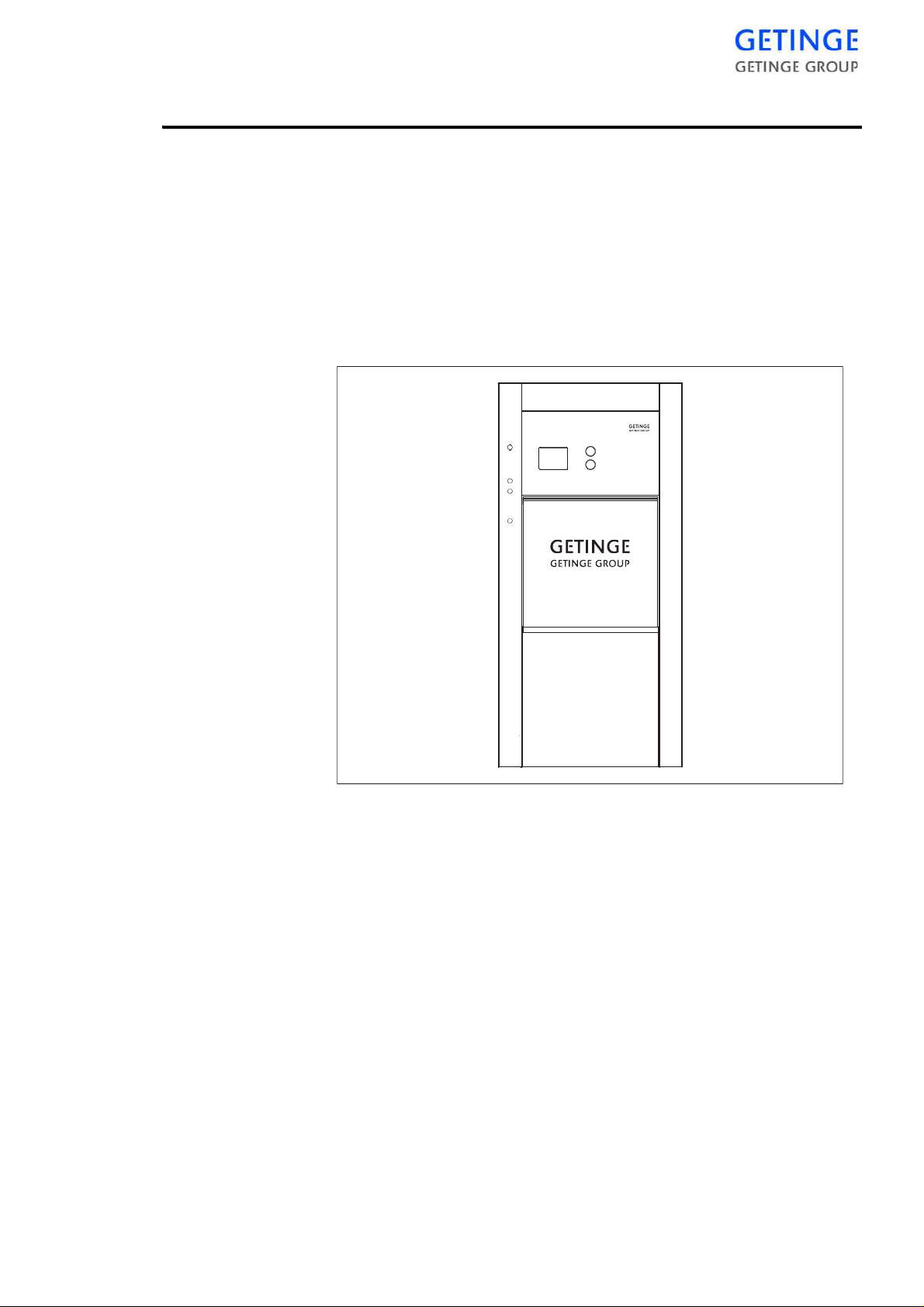
INTRODUCTION
HS 66
HS 66 is the designation of a series of GETINGE high-pressure autoclaves with vertically sliding automatic doors, all with the door opening
660 x 660 mm
There are both stand-alone and built-in versions.
The autoclaves are intended for sterilization of materials in the health
service as well as in industry. They are adapted to their particular functions by the choice of control equipment. This is built up around a
microprocessor and therefore provides a very large number of process
types, all characterized by exceptional accuracy in controlling the process parameters. The operator can call up on a display information on the
current process, current pro cess phase and the actual values of the
parameters while the process is in progress.
The dominant sterilizing agent is steam at a temperature of 121 -134 °C.
Material that is damaged by this temperature may be sterilized in some
autoclave models in formalin vapour at 55 - 80°C.
Most types of items can be treated in the HS 66-autoclaves, using
adapted programs:
Instruments, machine parts, glass, plastic, leather, textiles, hot or cold
liquids in open or vented containers and small rigid pressure-tight containers filled with liquids.
INTRODUCTION -
7
European standard EN 285 (Australia/New Zeeland, Standard AS 1410)
specifies the use of fixed programs only. However, the control equipment of HS 66-autoclaves allows the programs to be made variable during the time testing is in progress.
As not only the processes but door operation too are controlled automatically, the step to full automation of the handling of sterile items is not
a long one. The control unit is therefore prepared for controlling an
autoclave having a GETINGE ASF automatic loading and unloading
unit.
As with other GETINGE double-jacketed autoclaves, the external surface of the cham ber is more than half c overed by all-welded U-sections.. These stiffen the fla t walls of t he pressure vessel, and at the same
time accommodate the stea m which keeps the cham ber walls warm in
order to minimize condensation in the chamb er. The design principle
makes all welds accessible for visual i nspec tion aft er t he th ermal insulation has been removed.
A vacuum pump of the water-ring type removes air, steam and condensation from the chamber and door-gasket groove. The sealing water of
the pump is taken from an open tank which in some cases also supplies
the feedwater pump, on autoclaves with a steam generator, with water.
The condenser between the chamber and vacuum pump converts waste
steam to water. This reduction of the pump handling volume contributes
greatly to improving pump efficiency and protecting the pump and
waste pipes against high temperatures.
A well-damped discharge system after the vacuum pump and welldimensioned thermal insulation around the chamber mean that the autoclave affects the surroundings to an insignificant extent and is therefore
easy to position.
HS 66-autoclaves have to be supplied with electricity, cold water, compressed air and steam. When steam is supplied from a central steam-producing plant, its distribution system is required to be correctly pressurereduced, protected by a safety valve and produce a quality of steam
which is suitable in the context of sterilization. (For some versions the
pressure reducer is already fitted)
If the steam is not suitable in the context of sterilization, a steam generator can be installed inside the trim plates on all models. The task of the
8 -
INTRODUCTION
steam generator is to generate pure steam using the centrally produced
steam.
If there is no steam network or there are reasons for not using the steam
network, an electric steam generator may be installed inside the trim
plates on all models.
Overview of safety de vi ce s
Cladding and front panels must prevent access to the parts
of the installation that are normally accessible only to
trained personnel.
General access to an installation supplied without cladding, which should normally only be maintained by trained
personnel must be prevented. A convenient way of preventing access is to install the equipment in a lockable
area.
Additional information about the above safety components are given in
the “Safety checks”, “Utility data” a nd “Periodic maintenance” sec tions
of the TECHNICAL MANUAL.
Safety components
Every unit is equipped with a number of components with the specific
purpose of ensuring the safety of personnel. These items are marked
with a warning triangle below in the following documents:
•
•
•
These components have undergone special tests before being accepted
as safety components. For this reason, they must not be replaced with
components of any make or design that has not been appr oved by
GETINGE.
It is of the highest importance that the operational reliability of these
components is continuously upheld during their entire service life.
electrical diagrams
pipework diagrams
spare parts lists
The signs are used not only to indicate important components, but also
to draw attention to other safety factors that call for special attention,
such as dimensions, tolerances, materials, etc.
INTRODUCTION -
9

Doors
Emergency stop
The doors are closed and locked while the process is running and remain
locked in the event of media loss. The doors cannot be opened until the
pressure in the chamber has been equalized with the ambient pressure,
not even if fault management gives an opening command. The sliding
doors are operated by a compressed air cylinder which has a severe ly
throttled inlet. A drain valve with a considerably greater flow capaci ty
than the inlet is located in the bottom of the cylinder, which is pointing
upwards. Objects that obstruct the upward motion of the door pr ess
down a metal plate which op ens the drain valve, causing the do or
motion to stop. This prevents operator injuries and material damage. A
support latch holds the door so that it does not open if the pneumatic
operating cylinder loses pressure. When the pressure of the compressed
air is so low that the door cylinder cannot support the weight of the door,
the air is not capable of pulling away the support latch.
In the front panel, at the side of the door, there is a pushbutton with these
functions:
A On door operation.
B When the door is closed
Door interlock key
The front panel contains a key switch, intended for use whe n cleaning
the sterilizer or when it is necessary to reach into the chamber for any
reason.
With the key removed, the door cannot be closed. See also under
"Cleaning the chamber" in the Operation chapter.
Trim plates
Panels are possible to dismount by means of tools or keys. The panels
form a barrier for ope rators, but not for specially tra ined technicians.
Stainless steel surfaces within reach of the operating personnel are insulated and cooled to a harmless temperature.
to stop the door motion immediately during door operation. Pressing the button triggers an alarm. This alarm stops the door immediately:
The current process is aborted and all valves for media to the chamber are closed. This also triggers an alarm.
Valves
10 -
INTRODUCTION
If the equipment has electrically and/or pneumatically actuated valves
they are normally made to close by means of spring force. This prevents

Pressure vessels
Safety valves
undesired flow through the valves in case of power failure. A f ail safe
function is achieved.
The sterilizer chamber jacket and steam generator are pressure vessels,
designed and built in accordance with standards laid down by official
bodies charged with monitoring this area of safety.
The internal steam supply to the sterilizer is protected against excessive
supply pressure by a safety on the steam generator, the sterilizer or both.
The connected supply lines from external steam, water or compressed
air networks must be protected against exce ssive pressure by safety
valves. The sterilizer supplier is not responsible for these valves. Permitted supply media pressures are stated in “Utility data”.
Safety valves limit the system pressure, providing the last line of protection to prevent the design pressure of the vessel from being exceeded.
Safety valves are required to be inspected at prescribed intervals.
Monitoring the pressure behind the door seal
All valves admitting any medium to the chamber are kept closed until
the pressure behind the door seal is high enough to guarantee the tightness of the chamber.
Built-in electrical stea m generator
The sterilizer also has a fully-automatic built-in steam generator, with
tubular electric elements as the heat source.
Operation
The heating power is divided among a number of groups of elements.
The elements are controlled by a pressure switch with double changeover contacts, one for each heater element circuit. One group of contacts
limits the operating pressure of the steam generator. The other controls
reconnection of the power when the minimum pressure is reached.
Pressures higher than those stated on the electrical diagra m should not
be set, since the steam will be superheated when admitted to the sterilizer chamber. On the other hand, if the operating pressure is allowed to
fall too far, the steam tends to become wet, which is undesirable for sterilisation purposes.
INTRODUCTION -
11

A feedwater pump supplies the steam generator with water from a n integral water tank with air trap. The water level of the steam generator is
sensed by a device which controls the operation of the pump so that the
level is kept almost constant. Boil-dry protection cuts off the supply of
electric power to the elements when the water level is low.
See also “Steam generator settings and controls” under Advice and
instructions in the TECHNICAL MANUAL.
Control switch
The steam generator and sterilizer are controlled by the same switch. On
sterilizers with med double steam systems there is an extra shutoff button marked Steam generator.
Pressure regulation in power stages
The system prevents wear of the element contacts by switching the
power in and out in two stages at d ifferent pressure levels and with a
time offset between switch-on and switch-off for the first stage.
Spark-reduction connection
As well as shortening the life of electrical contacts, sparking at the contacts may also cause interference with nearby electronic equipment.
The anti-spark protection is based on fast-act ing a uxiliary rela ys t aking
over the load from the slow-breaking contacts of the pressure switch for
operating pressure, so largely eliminated sparking.
Safety valve, steam generator
The mandatory periodic check of the operation of the steam generator
safety valve can be done simply by means of the keyswitch described
below. See also the Maintenance chapter in the TECHNICAL MANUAL.
Keyswitch “Test pressure limiter”
When the key is in the safety valve check position, steam is produced
continuously and regardless of the setting of the operatin g pressure
switch.
Water level regulation
Version with conductive measurement
The Getinge conductive level system is designed for water with a conductivity above 2 μS/cm.
12 -
INTRODUCTION

The task of the level device is to sense and control the water level of the
steam generator. The main components are a sensitive relay and two
electrodes, the ends of which touch the water surface at the upper and
lower fill levels. Contact of the upper electrode with the water stops the
feedwater pump, whilst absence of contac t at th e low er elec trode st arts
the pump. A third, lowest, electrode cuts off the electric powe r supply
to the heating elements when the electrode loses contact with water; see
boil-dry protection below.
The type and sensitivity of the level relays can be adapted to varying
water conductivity. If the f eedwater is de-ionised, a high-sensitivity
level relay is required and the sensitiv ity setting must be increased as the
conductivity of the water decreases.
The sensitivity of the level relay is automatically adjusted at power up
to match varying conductivity.
The distance between the electrodes is another factor that affects the
overall sensitivity of the level control system.
Version with float
The GETINGE f loat-based level cont rol system is intended for water
with a conductivity of 0 to 2 μS/cm, but it can also be used for higher
conductivity.
The task of the level device is to sense and control the water level in th e
steam generator. The main components are a float with two level contacts and two relays. The level contacts change over at the upper and
lower fill levels. The upper contact stops and starts the feedwater pump,
whilst the lower contact cuts off the electric power supply to the heating
elements; see boil-dry protection below. The purpose of the relays is to
protect the float contacts from harmful currents.
Water-level monitoring
A lamp in the “reset level” button on the steam generator control panel
is lit when the water level is correct. On some models, the water level
can also be read off on a sight glass. The sight glass has two valves
which can be closed to prevent loss of water and steam in the event of
breakage of the sight glass.
Boil-dry protection
If the water filling fails, the boil-dry protection cuts of f the electric
power supply after a certain time, when the water level has fallen below
a minimum limit.
Overheat protection
This protection prevents the steam generator from overheating if the
boil-dry protection should fail to operate.
INTRODUCTION -
13

Overfilling protection
The timer relay prevents the steam generator over-filling with feedwater
if the level control system stops working.
“Reset level” button
If a fault occurs on any of the safety components of the steam generator,
it must be reset manually in accordance with applicable boiler regulations.
The button is also used when filling an empty steam generator with
water. See the Function check chapter in the INSTALLATION MANUAL.
“Test level limiter” button
This button is provides a quick test of the operation of the boil-dry protection. The test interrupts the level circuit without the need to reduce
the water level.
RCD
Safety switch
Some types of steam generator must be connected to the electric power
supply via a residual current device (RCD). See the Installation instruc-
tions chapter in the INSTALLATION MANUAL.
It must be possible to isolate all electric power supplies to the steam
generator with a safety switch. The safety switch must be locka ble in the
OFF position. See also chapter Installation in the INSTALLATION
MANUAL.
14 -
INTRODUCTION
THE PROCESS
A
B
C
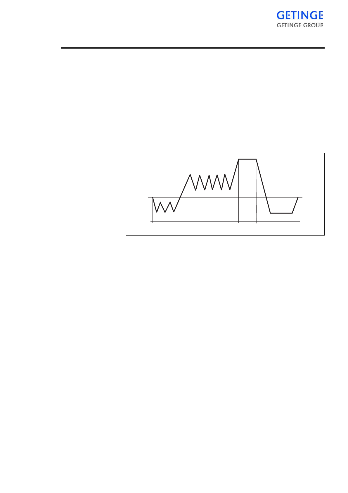
The steam sterilizing process
The universal steam autoclaving process can be divided into three main
phases:
APre-treatment
B Sterilizing
C Post-treatment
Pre-treatment
Sterilizing
It has been found that moisture is an essential element in achieving sterility with steam. It is therefore important that the steam comes into
close contact with the micro-organisms to be killed.
A pre-treatment phase consisting of a number of pressure variations following a certain pattern effectively removes air from various types of
goods and produces the moisture required in the subsequent sterilizing
phase. Depending on the equipment of the sterilizer, steam may pass
through before the evacuations.
Air removal when autoclaving liquids in open containers is by applying
a vacuum or by flowing steam, to ensure that the liquid does not boil
during the decompression periods in a pulsating procedure.
For sterilizers equipped with a computerized cont rol unit, the sterilizing
time starts at the instant in the pre-treatment phase of the process when
the chamber temperature sensor signals a temperature equal to or higher
than the sterilizing temperature specified for the current program. An
alarm sounds if the temperature sensor registers a value outside the temperature band, or if the temperature differs by more than the permitted
amount from the chosen sterilizing temperature.
THE PROCESS -
15

Post-treatment
When sterilizing liquids, the te mperature is measured with a temperature sensor in the load. The condition for countdown of sterilizing time
is that both temperature sensors in the chamber and the sensor in the
load indicate the programmed sterilizing temperature.
The purpose of the post-treatment is to normalize the temperature and
moisture content of the goo ds. All goods except liquids are therefore
exposed for a certain time to a vacuum below 70 mbar (a). After suc h
post-treatment. textiles may appear to increase in weight by about 1%.
This represents the normal addition of water that occurs during steam
autoclaving process.
Post-treatment of liquids that have been sterilized in open or half-closed
containers consists of a self-cooling period. During this period the pressure and temperature are lowered very slowly until the temperature is
well below the boiling point of the liquid. This process is speeded up by
applying a slight vacuum to the chamber when its pressure appr oaches
atmospheric.
NOTE: Liquids must only be processed in sterilizers which
have a program for this type of load.
Pressure equalization from vacuum takes place by admitting atmospheric air into t he cham ber via a f ilter tha t preve nts bact eria from entering the chamber. The efficiency of the filter is 99.998% for particles of
the order of 0.3 micron (0.0003 mm) in size.
The sterilizer door is kept closed by the door gasket until the pressure in
the chamber is equal to atmospheric pressure.
Process adaptation
A large number of factors such as type of goods, goods carrier, packaging material, etc. affect the result of the process. The control equipment
offers a number of features that can be used to optimize the processes to
suit the requirements of different customers. For further information,
see "User-programmable functions" in the TECHNICAL MANUAL.
16 -
THE PROCESS
Maintenance program
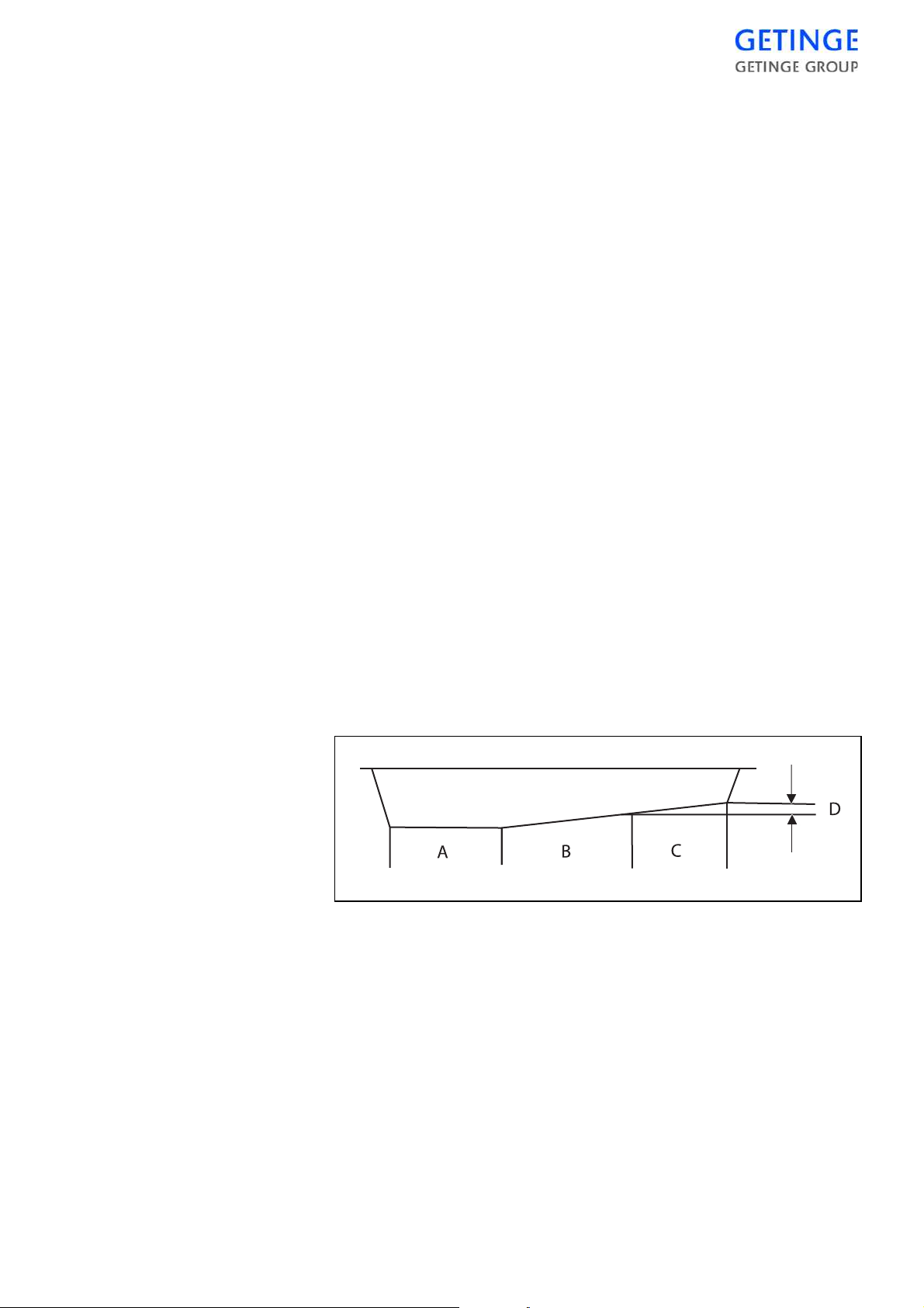
Leak test
Fully automatic process for steam autoclaves
With autoclaves equipped with an analogue pressure transducer the leak
test can easily be automatically performed. The leak test is to be performed with an empty chamber. The chamber additionally has to have
been warm, for example as a result of a heating program having been
run beforehand.
The checking process has its own program button (see program list)
which starts with the vacuum system evacuating the chamber. Depending on the equipment of the sterilizer, steam may pass through before
the evacuation. The pump in the vacuum system stops when a deep vacuum has been created. For a short period of time after this evacuation a
slight rise in the chamber pressure takes place which is not due to leakage but results from evaporation of condensate and temperature-volume
changes in the recently rarefied residual steam.
It is therefore not possible to establish that an increase in pressure in the
chamber is caused by leakage until conditions in the chamber have stabilized. It is not until about 10 minutes after the pump has stopped that
the pressure and time start to be measured.
A satisfactory leak test allows for a maximum permissible pressure rise
of 13 mbar / 10 minutes.
With double-ended autoclaves, the loading door opens after a completed leak test either automatically or manually, depending on how it
has been programmed.
A Normal vacuum 5 min.
B Stabilization of chamber atmosphere 10 min.
C Check time 10 min.
D Pressure stepping max. 13 mbar.
Documentation of the process
A panel printer prints out data logged during the process.
THE PROCESS -
17
See Components in the TECHNICAL MANUAL for printer settings
and maintenance.
The system stores the last process so that an “emergency printout” can
be produced afterwards if there is a problem with transmission of the
printout or with the printer itself.
If the system is fitted with a SUPERVISOR, the printer is connected to
that. Otherwise it is normally connected to the control system. SUPERVISOR is an inde pendent measu ring system that records the process
data of the sterilizer. See a lso Control unit in the TECHNICAL MANUAL for further information.
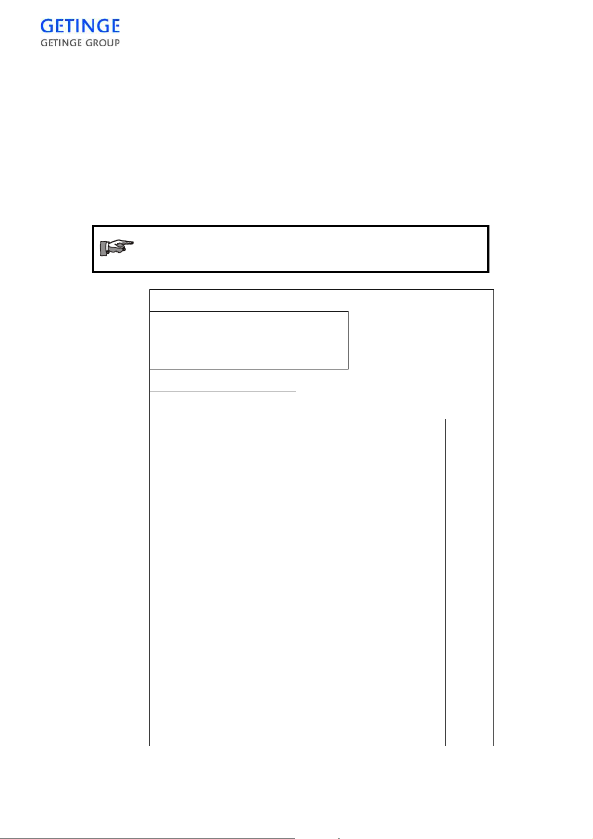
The illustration below is schematic and must not be used
as a template for evaluating individual process results.
13:47 29 06 04
SIGNATURE ………
..
PROCESS OK
00:24:58 71.2 132.5 85.2 0.995
PROCESS COMPLETE
00:23:39 75.5 132.5 85.2 0.039
EQUALIZATION
00:18:35 51.1 132.2 88.6 0.096
00:16:14 134.9 135.4 134.8 3.076
DRYING
HIGHEST TEMP 135.2C
LOWEST TEMP 134.9C
5
134.9C
6
18 -
THE PROCESS
00:16:08 135.0 135.5 134.9 3.094
POST-TREATMENT
00:12:07 134.1 134.3 134.0 3.039
STERILIZING
00:09:10 106.5 132.6 103.6 1.088
4

HEATING
00:08:50 115.8 132.5 115.6 1.880
00:08:33 107.8 132.6 104.3 1.107
POS PULSING
00:08:14 115.9 132.5 115.7 1.876
00:07:57 107.2 132.6 103.1 1.103
POS PULSING
00:07:38 116.0 132.6 115.7 1.880
00:07:21 106.0 132.6 100.1 1.119
POS PULSING
00:07:02 116.1 132.2 114.9 1.877
00:06:44 104.5 132.4 77.2 1.090
POS PULSING
00:06:24 116.6 132.3 87.4 1.875
00:05:52 92.0 132.5 34.0 0.835
POS PULSING
00:05:32 78.4 132.7 33.7 0.065
00:04:22 91.3 132.5 33.9 0.836
NEG PULSING
00:04:01 75.1 132.5 33.4 0.066
00:02:54 81.4 132.5 33.7 0.849
NEG PULSING
00:02:37 81.9 132.6 33.4 0.099
00:00:15 46.6 132.6 33.4 0.997
NEG PULSING
00:00:00 46.5 132.5 33.4 0.997
START
4
PROG. TIME AI00 AI01 AI02 AI03
PROGRAM: P1 POROUS LOAD 134
AI03 CHAMBER PRESSURE
AI02 AIR DETECTOR
THE PROCESS -
19

AI01 JACKET TEMP
A100 DRAIN TEMP
SIGNALS
DRYING AIR PULSE 00:00:00
DRYING STEAM PULSE 00:00:00
DRYING TIME 00:05:00
STERILIZING TIME 00:04:00
3
STER. TEMP.
POS. PULSE 5
NEG. PULSE 3
PARAMETER SET-
TINGS
CYCLE COUNTER :16
MACHINE NAME :HS55
PROCESS START 13:20:45
DATE 29/06/2004
1. The lower part shows the date and time when the process was
started and the type designation, number and cycle counter of the
sterilizer.
2. Above the heading “Parameter settings” there is a list of the parameters of the current program that can be changed with a parameter
code. In this example, sterilizing temperature in °C and times for
various sub-processes in hours, minutes and seconds.
134.0 C
2
1
3. Above the heading “Signals” there is a list of the parameters chosen
for printing.
4. Information about which program has been started, followed by
process logging.
5. Printed out if an error occurs during the process.
6. Signature line
Documentation of the process
An A4 printer prints out data logged during the process.
20 -
THE PROCESS
See Components in the TECHNICAL MANUAL for printer settings
and maintenance.
Printout is possible in four modes. The mode shown below is preset
before delivery and is recommended by GETINGE.
The system stores the last process so that an “emergency printout” can
be produced afterwards if there is a problem with transmission of the
printout or with the printer itself.
If the system is fitted with a PACS SUPERVISOR, the printer is connected to that. Otherwise it is normally connected to the control system.
PACS SUPERVISOR is an independent measuring system that records
the process data of the sterilizer. See also Control unit in the TECHNI-
CAL MANUAL for further information.
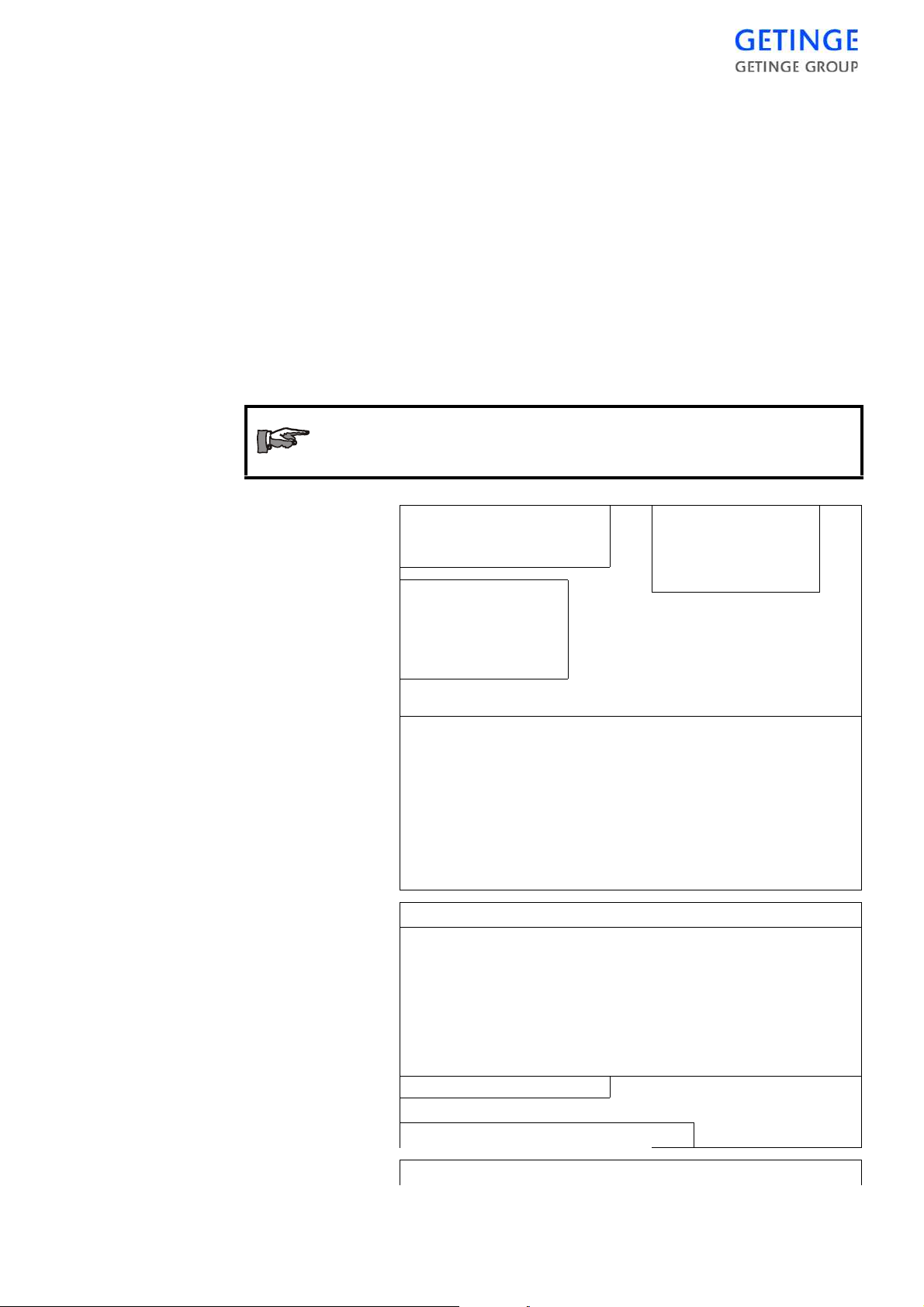
The illustration below is schematic and must not be used
as a template for evaluating individual process results.
DATE 16/05/2001 SIGNALS Page: 1
PROCESS START 08:01:36 AI00 DRAIN TEMP
AUTOCLAVE NAME HS6613-2 AI24 S DRAIN TEMP
AUTOCLAVE NUMBER 1
CYCLE COUNTER 5 AI27 S CHAMBER PRESS.
PARAMETERS
NEG. PULSE 3
POS. PULSE 5
STERILIZING TEMP134.0 C
STERLIZING TIME 00:07:00
DRYING TIME 00:05:00
DRYING STEAMPULSE 00:00:00
DRYING AIRPULSE00:00:00
PROGRAM: P1 POROUS LOAD 13 4
--------------------------------------------------------------------------------------------------------------------------------------------------PROGTIME AI00 AI24 AI03 AI27 AI04 AI05
START
00:00:01 83,1 82,7 1.000 1.021 89.2 89.1
NEG. PULSE
00:00:23 82.3 82.3 0.955 0.960 101.4 101.0
00:02:53 67.4 67.4 0.100 0.097 105.6 104.1
POS. PULSE
00:00:03 93.4 93.3 0.822 0.822 120.6 120.8
00:00:58 117.5 117.5 1.865 1.865 129.9 129.9
HEAT UP
00:00:49 104.5 104.5 1.245 1.251 113.5 113.7
STERILIZING
00:01:14 134.4 134.3 3.052 3.065 134.1 133.9
00:03:14 135.0 135.0 3.116 3.120 135.3 135.4
IDENTIFICATION: HS6613-2 1 CYCLE COUNTER: 5 Page: 2
--------------------------------------------------------------------------------------------------------------------------------------------------PROGTIME AI00 AI24 AI03 AI27 AI04 AI05
00:00:14 135.0 135.0 3.116 3.116 135.2 135.3
LOWEST TEMP 134.9
DRYING
00:00:18 135.0 135.0 3.110 3.113 135.2 135.3
HIGHEST TEMP 135.2
00:02:12 60.1 59.9 0.130 0.124 105.2 105.4
EQUALIZATION
00:03:16 89.9 89.8 0.055 0.052 119.6 119.2
PROCESS COMPLETE
00:33:27 93.7 93.6 0.987 0.987 130.3 130.1
PROCESS FAILURE
---------------------------------------------------------------------------------------------------------------------------------------------------
1
2
5
AI03 CHAMBER PRESS.
AI04 T1
AI05 TI2
3
4
4
SIGNATURE:__________________________________
DATE : 16/05/2001 PARAMETERS
6
Page: 3
THE PROCESS -
21

PROCESS START : 08:01:36 NEG. PULSE 3
0 . 0
AUTOCLAVE NAME : HS6613-2 POS. PULSE 5
AUTOCLAVE NUMBER : 1 STERILIZING TEMP134.0 C
CYCLE COUNTER : 5 STERLIZING TIME 00:07:00
PROGRAM: P1 POR O U S LOA D 13 4
----------------------------------------------------------------------------------------------------------------------------------------CHAMBER PRESS DRAIN TEMP
DRYING TIME 00:05:00
DRYING STEAMPULSE 00:00 :00
DRYING AIRPULSE00:00:00
7
1 In the top part, the date and time when the process was
started and the type designation, number and cycle counter of the sterilizer are shown.
2 Parameters of the current program that can be changed
with a parameter code are listed under PARAMETERS.
In this example, sterilizing temperature in °C and times
for various sub-processes in hours, minutes and seconds.
3 The parameters chosen for printing are listed under
SIGNALS.
4 Information about which program has been started, fol-
lowed by process logging.
5 Printed out if an error occurs during the process.
6 These lines are printed out after a faulty process. Identi-
fication code of the person who entered the password and
a line for a signature.
7 Graphical representation of the process
22 -
THE PROCESS

INSTRUMENTS
2
3
5
1
4
7
6
Loading side
1. Steam supply pressure gauge. 5. Control switch.
2. Pressure gauge chamber pressure. 6. Door interlock key
3. Operator's control panel 7. Emergency stop.
4. Panel lock.
Operator's control panel
Learn the function of the control panel by studying
chapter Control unit PACS 3500.
Door-blocking key
See chapter Introduction, “Safety devices, an overview”.
Emergency stop
See chapter Introduction, “Safety devices, an overview”.
INSTRUMENTS -
23

Unloading side
2
3
1
4
1. Recorder for temperature and
pressure.
2. Pressure gauge chamber pressure. 4. Emergency stop.
3. Operator’s control panel
Recorder
See recorder operating instructions in the TECHNICAL MANUAL
chapter Components.
Operator.s control panel
Learn the function of the control panel by studying chapter Control unit
PACS 3500.
Emergency stop
See chapter Introduction, “Safety devices, an overview”.
24 -
INSTRUMENTS

OPERATION
Program start
Where applicable, the operator m ust s tate process parameters and other
information requested by the contr ol system. On equipment where an
authorisation code for programs not intended for routine sterilization is
activated, the operator must also enter an authorisation code immediately after startup.
Via operator panel Avanti
To start a cycle:
•
Select the desired cycle.
•
Load goods and close the door.
•
Wait until the Door closed indicator lights
up and the
Now the machine is ready to start.
•
Start the cycle.
Process startup is prevented if:
•
there is an unacknowledged alarm
•
the door is not closed and interlocked in accordance with the conditions
•
the control system has detected an interlocking error (affects door
safety)
•
the keyswitch for manual stepping is activated
•
the keyswitch for door blocking has been activated (only if there is a
keyswitch)
•
media supply, eg steam or cooling water, is not available (only if the
sterilizer is equipped with sensors for this).
Start
button becomes visible.
•
the jacket temperature has not been reached or is too high (only if the
process includes jacket heating)
OPERATION -
25

Authorization protected programs only:
Message
After the start button is pressed, the operator is
requested to enter the authorization code.
If the operator chooses to attempt to start the sterilizer, even though
starting is blocked, the operator panel display shows a message referring to an essential condition that is not met.
•
JACKET TEMP HIGH - Indicates that lowering of jacket temperature is in progress.
•
JACKET TEMP LOW - Indicates that raising of jacket temperature
is in progress.
•
STEPPING KEY ON - Indicates that key switch for stepping is on.
•
PRINTING ACTIVE - Indicates that printing from the printer is
blocking the start of a new program.
•
UNACKNOWLEDGED ALARM – Indicates that a previous alarm
has not been acknowledged and blocks the start of a new program.
•
SEAL PRESSURE – Indicates that the door seal is pressurised.
[START]
•
•
•
•
•
•
Alarms - Avanti
If a fault occurs, in standby or during a cycle, the system goes to an
alarm phase. This is an exceptional situation, but it is normally not
dangerous. The current cycle is stopped and output signals from the
control system go to settings that maintain the safety of personnel, the
unit, and the load.
DOOR KEYSWITCH - Indicates that the keyswitch for cleaning is
on.
DOOR NOT CLOSED - Indicates that a sterilizer door is not properly closed.
LOW WATER LEVEL – Indicates that the water le vel in the ta nk is
low.
COMPRESSED AIR – Indicates that the pressure of the air supply is
low.
DEGASSING TANK – Indicates that the temperature in the degassing tank is low.
START CONDITION - Indicates that a starting condition specific to
the type of unit is not met.
(Steam, cooling water, formalin bottle or vent ilation at formalin sterilizers)
26 -
OPERATION

•
An alarm signal goes off and the relevant fault code is
displayed on the cycle screen, while the cycle screen’s
background turns red.
•
After the alarm signal goes silent, the
Alarm indicator in the status field blinks.
•
If the unit is equipped with a printer, the alarm text is
also printed out as part of the cycle log.
In case of alarm:
Read the error message and correct the fault.
The fault codes are explained later in this chapter.
In case of an error concerning a temperature sensor, a
pressure transducer or the Back-up battery a service technician is to be called for.
Blowing safety valve
If a safety valve blows off:
•
Press the EMERGENCY STOP button.
•
If this has no effect, cut off the electric power supply with the control
switch on the front of the unit.
•
In an emergency, the power supply can be cut off with the working
switch.
Send for a service technician without delay.
On power failure or if the control switch or working switch
of the sterilizer had to be turned off during a process, there
is a risk of leakage a t the door. Safe ty measure when there
is positive pressure in the chamber:
KEEP WELL AWAY FROM THE DOOR AND CALL A TECHNICIAN!
OPERATION -
27

Alarms in standby mode
An alarm from an idle sterilizer prevents it being started.
•
Call a technician.
If the load contains liquids, choosing the wrong program
may endanger personnel and equipment.
Alarms during a cycle / Avanti
A fault occurring during a cycle stops the cycl e. All valves close in
order to stabilize the conditions in the chamber.
An alarm signal sounds and the relevant error code is
displayed on the cycle screen. The cycle screen’s
background turns red and the Alarm indicator is shown.
•
Press
Silent alarm signal
•
To show detailed alarm information press
The most recent alarm is displayed at the top of the list.
Press the desired alarm to get detailed information
about the alarm.
•
After acknowledging the alarm, the following
alternatives are available:
·
Automatic quick stop of the cycle
·
Call a technician.
Automatic quick stop of the cycle
To quick stop:
•
Depending on how the cycle is set, the cycle stops
automatically or the cycle stops until the user presses
Start
.
to turn off the alarm signal.
Alarm
.
28 -
OPERATION
•
The Finished Cycle indicator lights up red after the
cycle is finished.
•
Acknowledge the alarm by pressing
More
and then
Ack.

•
If the unit is equipped with a printer, the alarm text is
also printed out as part of the cycle log.
Call a technician.
In case of a serious fault, always call a technician.
After the technician activates the key switch to the Stepping/Authorized
user setting, the technician has the following alternatives:
•
Restart the cycle where it stopped.
•
Move the cycle to another phase and start the cycle from there or
move it to the end.
To restart:
•
Press
Start
.
To move to a different step:
•
Press
More
and then repeatedly press
Step
.
After the cycle ends:
•
The Finished Cycle indicator lights up red after the
cycle is finished.
•
Acknowledge the alarm by pressing
•
If the unit is equipped with a printer, the alarm text is
also printed out as part of the cycle log.
For safety reasons, it is not possible to step past a pressure equalisation phase or a cooling phase.
Shutting off the alarm indicator - Avanti.
More
and then
Ack.
•
Finish the current cycle.
OPERATION -
29

Repeated alarms
•
Press
More
.
•
Press
Ack.
to acknowledge the alarm, by which the
Alarm indicator goes out and the red background
disappears.
To reset certain types of faults, a technicia n must first activat e the key
switch for Stepping / Authorized users.
If the process repeatedly hangs at the same alarm point, call a technician
to step the process to the end. If several faults occur, only the last one is
displayed.
In certain phases, sensor faults prevent stepping of the
program.
Stepping may only be done by trained personnel.
Alarm printout in process documentation
Where a main fault causes one or more secondary faults, the operator
panel shows on the most recent fault. If the unit has a printer or similar,
all faults are printed out, together with the time when they occurred.
Doors
When a fault has occurred, the unloading door of a double-ended sterilizer will not open. Exceptions are errors that occur so late in the process
that unlocking of the door has begun.
The door can only b e opened when the corr ect password has been
entered. For further information, see the menu description in the Con-
trol unit chapter.
Steam generator alarms
Alarms from the steam generator may be due to the operating pr essure
being exceeded or the water level in the steam generator falling below
the minimum. Low water level may also indicate that the boiler water
quality is beginning to be very poor and that the water should therefore
be emptied.
Call a service tech nician to analyse and correct the fault, with the aid of
the description in the Advice and instructions chapter in the TECHNICAL MANUAL.
30 -
OPERATION

Error codes
NOTE!
Important where a steam generator safety valve has been
blowing off for a long time and the chamber is under pressure at the same time.
Only switch off the sterilizer control switch as a last re sort,
because doing so disables certain safety functions.
Instead, call a service technician who can trip the steam
generator circuit-breakers.
The error messages listed below are defined in the control system. If
more than one error occurs consecutively, only the error code for the
last error is displayed.
If the sterilizer is equipped with a printer, the error message is printed
out. For secondary errors, all error messages are printed out.
Information about the last twenty faults is saved in the control system
and is accessible in the service menu. If the sterilizer has a printer, this
information can be printed out.
Service codes
When the word “S E RV ICE ” app e ars o n th e d is pla y , se rv ice is re q uire d
and must be carried out by a service technician. See below for explanations of the codes.
NOTE!
No error has occurred.
The sterilizer can still be used.
Error code/
Message
BATTERY
ERROR
AI FAILCHAMBER
Explanation
The backup battery of the control system is
flat. Programs and stored parameters may
have been lost.
Chamber temperature sensor defective.
OPERATION -
31
Error code/
Message
Explanation
AI FAIL-
Jacket temperature sensor defective.
JACKET
AI FAIL-
Pressure transducer defective.
PRESSURE
AI FAIL-LOAD Load temperature sensor defective.
NOTE: Not present on all sterilizers.
AI FAILDEGASS.
De-aeration temperature sensor defective.
NOTE: Not present on all sterilizers.
Mistakes when correcting the above ty pes of fa ult s may
lead to situations where there is a risk of injury.
Always call a trained service technician.
Error code Explanation
High pressure The chamber pressure has been too high dur-
ing the sterile phase. This may indicate the
presence of air or non-condensable gases. The
actual pressure in the chamber is compared to
a theoretical saturation pressure calculated
from the sterile temperature + 3°C. A message
is printed in the alarm log when the error
occurs.
32 -
OPERATION
Low pressure The chamber pressure has been too low during
the sterile phase. This may indicate a faulty or
improperly calibrated sensor. The actual pressure in the chamber is compared with a theoretical saturation pressure calculated from the
sterile temperature. A message is printed in
the alarm log when the error occurs.
HIGH JACKET
TEMP
GASKET
The jacket temperature has been too high during part of the process.
Door gasket pressure too low.
FAILURE
DOOR FAILURE Door(s) not closed and interlocked.
PUMP FAILURE Vacuum pump has stopped.
HIGH TEMPER-
ATURE
The chamber temperature has been above the
permitted limit during the sterilization phase.

Error code Explanation
LOW TEMPER-
ATURE
PHASE TIME-
OUT
The chamber temperature has been below the
permitted limit during the sterilization phase.
The phase named on the display exceeded the
time limits for completion. Chec k whether the
cause is a component fault or media fault.
POST. TIMEOUT The post-treatment exceeded the times limits
for completion. Check whether the cause is a
component fault or media fault.
MAINTENANCE This message appears when the programmed
service interval has elapsed and the current
process is complete. The message continues to
be displayed until it is de-activated by the
service technician.
The autoclave can still be used.
Call a service engineer immediately.
MANUAL OUTPUTS
A digital output has been manually switched
off or on. Call a service technician to re set the
output to auto mode.
LEAK RATE
FAIL
SUPERVISOR
ERROR
POWER
FAILURE
EMERGENCY
STOP
STEAM GENERATOR
DOOR INTERLOCK
GASKET INTERLOCK
An automatic leak test has failed.
The Supervisor’s independent monitoring of
process time and temperature conditions has
indicated that these have not been fulfilled and
have triggered an alarm.
There has been a power failure longer than 10
seconds.
The program has been stopped with the emergency stop button.
The supply of feedwater to the steam generator has stopped working.
The independent safety interlocking of media
admission to th e chamber, as co ntrolled by the
door switch, is faulty.
The independent safety interlocking of media
admission to th e chamber, as co ntrolled by the
gasket pressure switch, is faulty.
PRESS. INTERLOCK
The independent safety interlocking of the
door function, as controlled by the chamber
pressure switch,pressure monitor or the
Supervisor, is faulty.
OPERATION -
33

Error code Explanation
TEMP. INTER-
LOCK
I/O FAULT The control system has lost communication
WATER
SUPPLY
COMPR.AIR
SUPPLY
DEGAS. TANK
FAIL
The independent safety interlocking of the
door function, as controlled by the load temperature switch, or the Supervisor, is faulty.
NOTE: Not present on all sterilizers.
with the input or output cards.
Call a service engineer immediately.
The water level in the tank is too low.
Pressure of incoming compressed air is too
low.
The temperature in the degassing tank has
fallen below the permitted value.
NOTE: Not present on all sterilizers.
General advice when using the sterilizer
•
Keep the sterilizer door closed when the unit is not in use.
•
Read the section “General advice on packaging material” in the
guide below.
•
If it is difficult to get items dry, the post -treatment stage can be modified. See the guide “Cycle modification according to the type of
load” further down.
•
Read the manual for the medical device to be sterilized before starting the process.
•
Be alert to everything that appears unusual such as leaks, humming
solenoid valves, stickily mechanical devices etc. Remedy the situation before it becomes a malfunction.
Heating of load
Heating of items to be processed may jeopardie sterilization result due
to poor humidification. Make sure appropriate process has been chosen
before loading the sterilizer.
34 -
OPERATION

Fire hazard
There have been reports of textile loads catching fire in the sterilizer
chamber. In all cases this has been due to the load becoming excessively
dry and hot. This can happen in two ways:
•
The load has been placed in a heated chamber and left for a long time
without the process being started. Ignition is believed to take place
when the load is moistened again on the admission of steam to the
chamber.
•
The load is left in the chamber for a long time without the process
being completed. This probably happens when the process has been
interrupted because of a fault and the load has not been taken out of
the chamber.
Ignition takes place when the process is completed and the load is
exposed to air.
Users should be aware of the risks and establish procedures to ensure
that loads are not left in a heated chamber for longer than necessary.
Weekly cleaning - Avanti
External cleaning.
Clean stainless steel surfaces on the outside of the sterilizer with a
standard household cleaner that does not contain abrasives. Take care
when cleaning painted surfaces, texts, and plastic parts.
Cleaning the chamber
When cleaning inside the chamber, a key switch on the front can be used
to block the door open, and shut off chamber preheating at the same
time.
On double-ended steriliz ers, the same key switch can also be use d to
open and block the unloading door for better access; see below.
•
With the sterilizer is in standby mode, turn the key
switch to the locked position and remove the key. The
text “DOOR KEY SWITCH” appears on the operator
panel display.
•
Open the door by pressing the
sterilizer cool down before starting work.
Open
button. Let the
OPERATION -
35

The sterilizer should have cooled down before cleaning.
When the key switch cannot be constantly observed, the
person doing the cleaning must always take the key with
them. This is to ensure that no-one mistakenly resets the
key switch.
•
Clean the strainer in the chamber floor drain.
•
Remove any shelves, guides, and bottom plates and
clean the inside of the sterilizer chamber.
Use a general-purpose chlorine-free cleaner. Scouring
powder may be used occasionally on stubborn stains.
Never use steel wool.
Sterilizers that are often used to sterilize products
containing salt require especially thorough cleaning,
since residual deposits may even have a corrosive
affect on stainless steel. An acidic cleaning agent
followed by careful rinsing is most suitable for the
purpose.
•
After cleaning, insert the key in the key switch and turn
it to the initial position.
•
•
•
Bowie Dick testing
The purpose of the Bowie Dick test is to reve al deficie ncie s in the abi lity of the sterilizer to expel air and reveal leaks or an excessive content
of non-condensable gases in the steam. In testing in accordance with EN
285, (or applicable national standard) an indicator paper is placed in the
centre of a test pack. The pack, which must be 220 - 300 mm square and
approx. 250 mm high, must consist of folded cloths of 100% cotton. The
pre-treatment of the te st programme must be identical to t he pre-treatment for the processes used for routine sterilization, while the steriliza -
Then close the door by pressing the
On double-ended sterilizers, the unloading door can be
opened for cleaning by repeating steps in the points
above.
Note! Note that there may be restrictions on door
opening on SPF sterilizers and sterilizers with
controlled work flow.
When cleaning is complete, both doors must be closed
and the key must be left in the key switch.
Close
button.
36 -
OPERATION
tion time may be adapted to the performance of the sterilizer but must
not exceed 3.5 minutes.
When the indicator paper has be en sufficiently exposed to steam at a
particular temperature, further exposure tends to hide the indication of
any deficiencies. GETINGE’s Bowie Dick programme is there fore
tested with the shortest possible sterilization time so that any deficiencies are not concealed by overexposure.
In day-to-day work, the above, standardised test packs for the sake of
convenience are sometimes replaced by various types of disposable
packs which are manufactured by a large number of manufacturers. As
these packs are generally even more sensitive to overexposure than the
standardised test pack, it is extremely important to c hoose the correct
make. Test packs in accordance with BS 7720 :1995 must be used for
GETINGE’s Bowie Dick programme.
Approved consu m ables
Consumables are used for different purposes as packaging for goods to
be sterilized, for testing, for replacement of sterilizer parts with limited
life or a sterilization media for low-temperat ure sterilizing. The list of
consumables below is intended as a guide to be used with GETINGE’s
CE-marked sterilizers.
Always check whether consumables have a use-by date
before using them.
Articles for packing items to be sterilized
Packaging materials must be matched to the method of sterilizing, the
load carrier and the goods to be sterilized. To guarantee compatibility
with GETINGE sterilizers, it is the responsibility of the user to ensure
that packaging material and methods used conform to European standard EN868-1, the other parts of which also specify particular requirements for different types of packaging material.
Packaging material for steam sterili zation
Getinge AB recommends warping in paper for textile packages and for
instrument grilles in baskets and containers.
Getinge AB recommends paper/plastic bags for separately packed articles.
OPERATION -
37

Packaging material for formaldehyde
For formaldehyde sterilizing, we recommend pape r/plastic bags
intended for steam sterilizing.
Articles for test purposes
The user is responsible for maintaining a routine check of the operation
of the sterilizer in accordance with European standard EN17665. There
are various types of test articles on the market to assist the user.
Chemical indicators
Chemical indicators used when testing various types of sterilizer must
conform to European standard EN867-1, the other parts of which also
specify particular requirements for different types of indicator.
Getinge AB recommends using chemical indicators in steam sterilization processes. For other types of processes it the user’s responsibility
to evaluate whether individual makes are applicable to the GETINGE
sterilizer process.
An established test method in which chemical indicators are used is the
Bowie-Dick test, with test packages or its equivalent with a disposable
package. For information see also under “Bowie-Dick testing”.
Biological indicators
Biological indicators used when testing various types of sterilizer must
conform to European standard EN866-1, the other parts of which also
specify particular requirements for different types of indicator.
Getinge AB recommends using biological indicators in steam sterilization processes. For other types of processes it the user’s responsibility
to evaluate whether individual makes are applicable to the GETINGE
sterilizer process.
Sterilizer parts for periodic replacement
Spare parts
So that correct operation and product safety can be guaranteed, parts for
recorders, printers or periodic maintenance must be genuine GETINGE
spare parts or parts approved by Getinge Infection Control. Article
numbers of genuine parts are stated in the relevant sections of the service manual.
Sterilization media for low-temperature sterilising with
formaldehyde sterilizers
Low-temperature sterilizing can only be done with special sterilizers
intended for the purpose. During sterilizing with formal dehyde, the
medium is added from containers attached to the sterilizer.
38 -
OPERATION
Formaldehyde solution
Containers holding formald ehyde solution are brought to the site an d
attached to the sterilizer by the operator.

Accessories
Where relevant, details of concentration, volume, packaging, handling
and properties are described under Operating instructions and under
“General advice on formaldehyde sterilizers”.
The sterilizer's CE label makes the manufacturer responsible for
ensuring that its product safety and function satisfies the strict
requirements laid out in the relevant EC directive. Accessories that are
mechanically, electrically or otherwise connected to the ster ilizer must
be compatible with this. As a result, only equipment that has been
evaluated by Getinge AB and registered as approved equipment may be
used together with the sterilizer.
Should non-approved equipment be used, Getinge AB
exempts itself of all product liability for the sterili zer and its
CE label.
Approved accessories
The accessories listed below are compatible with the sterilizer once the
sterilizer has been configured to function with the a ccessory in question.
Such configuration shall be performed by a professional authorized by
Getinge Sterilization AB.
Accessories for extended
documentation, etc.
1 A4-Printer EPSON LX-300 X X X X X
2A4-Printer LEXMARK XXXX X
Loading equipment
accessories
3 Shelf Rack (Light load) X X X
HS44 HS55 HS66 HS69 HS
Floor
Loaded
4 Shelf (light load) X X
5 Shelf Rack (heavy load) X X X
6 Shelf (heavy load) X X
7 Rails for Shelf Rack X X
8 Rails for Baskets X X
OPERATION -
39

9 Rails for AGS X X
10 Support bar (Rails for basket X X
11 Loading Platform X X
12 Loading Module X X
13 L-Rails (Extendable Shelves) X X
14 Extendable Shelves (perfo) X X
15 Extendable Shelves (Wire) X X
16 Sterilizer Basket (DIN)
X X
(600*300*150/290)
17 600*400*115/150/290) X X
18 Sterilizer Basket (ISO)
X X
(100) / (200)
19 Sterilizer Basket (SPRI)
XX
(100) / (200)
20 Sterilizer Basket (SPRI-
X X
Swedish) (100) / (200)
21 Automatic Loader (Basket) X X
22 Automatic Unloader
X X
(Basket)
23 Automatic Loader (Racks) X X
24 Automatic Unloader (Racks) X X
25 Basket Feeder (Manual) X X
40 -
OPERATION
26 Loading Trolley Fix Height X X X
27 Loading Trolley Height Adj.
X
(Racks)
28 LT FIXED 6606/6613HL/
X
633-07
29 LT FIXED 6610/6620HL/
X
633-10
30 LT FIXED FOR 6613/633-
X
13
31 LT FIXED FOR 6617 X
32 LT FIXED SAL FOR 6610/
X
633-10
33 LT FIXED SAL FOR 6613/
X
633-13

34 LT FIXED SAL PD 6610/
633-10
X
35 LT FIXED SAL PD 6613/
X
633-13
36 LT H/A 6610/6620HL/6910/
X X
633-10
37 LT H/A FOR 6613/6913/
XX
633-13
38 LT H/A FOR 6617 X
39 LT H/A SAL 6x10/633-10 X
40 LT H/A SAL 6613/6913/
X X
633-13
41 LT H/A SAL PD 6x10/633-
X
10
42 LT H/A SAL PD 6x13/633-
X
13
Other accessories.
43 Air Compressor 175 EO-24 X X
44 Air Compressor 55E-24 X X
45 Water Treatment System
X X
"RO 51"
46 Water Softener Princess
XX
MIDI
47 Water Softener Princess
X X
TURBO
48 Water Chiller MINI X X X
49 Water Chiller MIDI X X X
50 Water Chiller MAXI X X X
51 AGS X X
52NetCOM XXXX X
53 Free standing steam
X X X
generator
OPERATION -
41

42 -
OPERATION

OPERATION INSTRUCTIONS
The following operating instruction deals with the day-today use of the sterilizer.
A further copy of this operating instruction, together with
the program combination, is packaged with the sterilizer
when it is dispatched from the factory.
These documents must be displayed so that the personnel
can read them when working at the operator panel.
Use
This sterilizer must not be used for processing other m aterial than stated in the program combination list.
Pathogenic material must not be sterilized in this sterilizer.
Warning! Fire hazard!
Do not leave goods in a heated chamber. See chapter Oper-
ation.
Beware of hot surfaces inside the st erilizer chambe r when
the door is open!
Keep the sterilizer doors closed as much as possible to
reduce energy loss and minimise temperature rise in the
room.
OPERATION INSTRUCTIONS -
43

Daily prepara t ion s
•
Learn the functions of the control buttons and signal lamps by studying the Instruments and Control unit chapters. Find out how the
user-programmable parameters are set on this unit.
•
Open valves for water, air and, where applicable, steam.
•
Switch on the mains switch of the unit.
•
Check that recording instruments and printers have sufficient paper.
The paper of recording instrument shows a red line when it is nearly
finished.
•
Run the first steam sterilization process of the day with t he chamber
empty. This heats up and drains the system pipework.
Running a process
Select the desired program. The selected program is indicated on the
•
control panel.
Parameter password
•
Before a selectable parameter can be changed, a parameter password
must be entered, after which all parameters (see Program combination) can be changed.
Password-protected programs
•
Programs that are not intended to be used routinely are protected
with a password. Some degree of consideration is called for before a
password-protected programs is chosen. Examples include test programs, programs for emergency situations, programs with selectable
parameters or programs using some sterilization medium other than
steam.
•
Load the sterilizer.
Start via operator panel Avanti
•
Make sure that cycle media are available.
•
Close the door by pressing
Close
.
44 -
OPERATION INSTRUCTIONS
•
If the “Door locked” indicator is lit and
the
Start
button can be selected, the
machine is ready to start.

If the lamp does not light up, start is prevented for some
reason (also see chapter Operation and Control unit).
•
Choose the cycle by pressing the
button in the button field.
In order to run the latest cycle, this step
can be skipped.
•
Press
Start
to start the cycle.
After completion of the process
Beware of hot surfa ces ins ide the sterili zer chamber when do or is
open!
Cycles
The control panel displays progress of the process.
Operating from the operator panel Avanti
•
The “Finished cycle” indicator lights up green after an
error-free cycle is completed.
•
The panel lights up green and an acknowledgement
key
lights up on the completion of an error-free process.
(Does not apply to automatic loaders)
•
Press
Open
if the door on the discharge side does not
open automatically.
Process check
Check that the completed process has been carried out correctly by
comparing the process printout with a corresponding type load printout
from the sterilizer validation.
OPERATION INSTRUCTIONS -
45
Goods handling
Remember that the goods may contain a c onsiderable amount of heat
when unloaded. Position them with regard to a good working environment.
Note that the goods may be very hot immediately after
unloading.
Let the goods cool down or wear safety gloves to handle
them.
Long sterilizers can take two load carriers in a row. Use a
hook (ordered separately) to reach into the chamber and
extract the inner load carrier.
Things to do when the work is finished
Unless otherwise prescribed by local rules:
•
Turn off the control power supply by the switch on the front.
•
Inspect the strainer in the bottom of the chamber and clean it if necessary.
•
Close valves for air, water and, if used, steam and gas.
If necessary:
•
Shut down the sterilizer for long enough to let it cool down, eg overnight.
•
Clean the inside of the chamber. Use a chlorine-free cleaner if necessary.
The sterilizer must always be cold when cleaned. To prevent injury, switch off the power to the control system.
The cleaning instruction is given in the section “General advice on
using the sterilizer” in the Operation chapter.
46 -
OPERATION INSTRUCTIONS
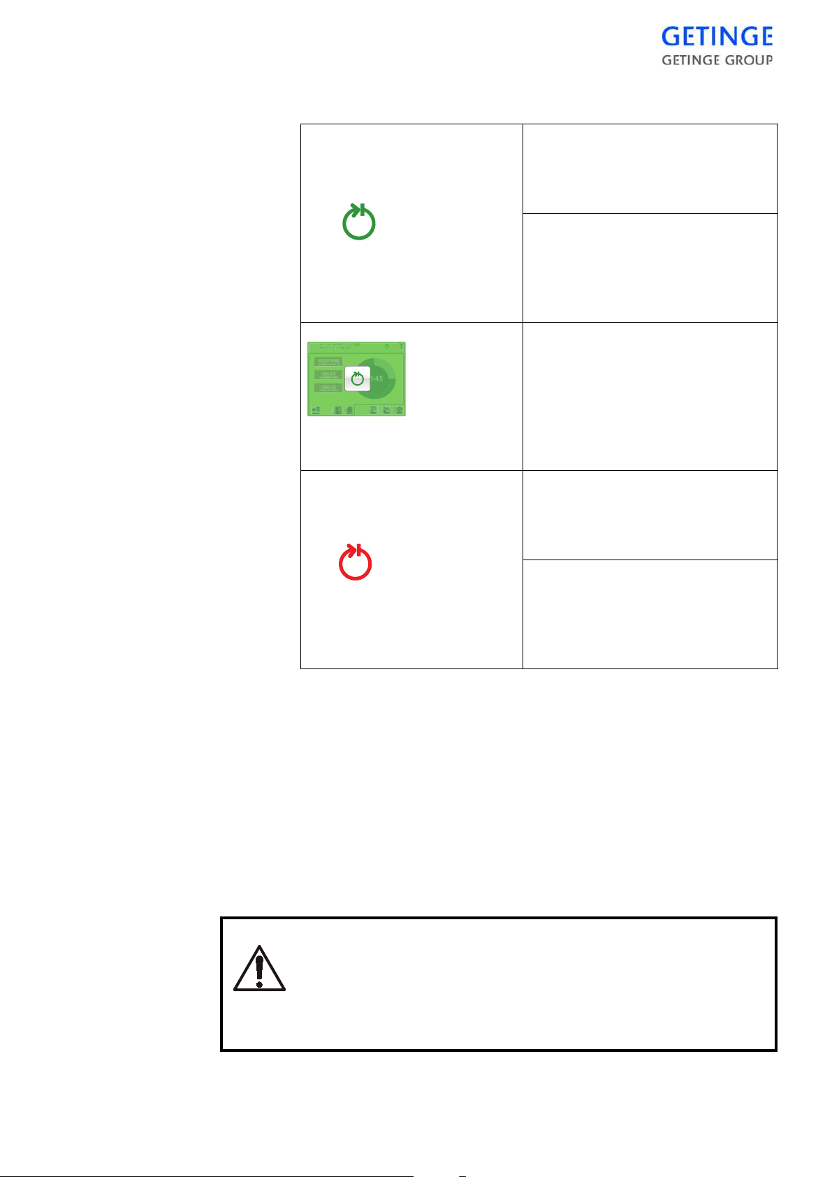
To interpret the “Finished cycle” indicator
Normal routine cycle:
After completion of fault-free normal routine cycle, the indicator
shows a steady green light.
Maintenance cycles:
After a completed, fault-free automatic leakage test or filte r sterilization, for example, the indicator
shows a flashing green light.
Normal routine program:
On the completion of an error-free
routine process, the panel lights up
green and an acknowledgement
key lights up.
(Does not apply to automatic loaders)
Normal routine cycle with fault:
After completion of stepped or
alarmed normal routine cycle, the
indicator shows a steady red light.
Maintenance cycles with fault:
After completion of a stepped or
alarmed maintenance cycle the
indicator shows a flashing red
light.
Stopping the program or a blowing safety valve
In an emergency, the program can be stopped or a safety valve that is
blowing off can be made to close, by means of the EMERGENCY
STOP button on the front panel, without disabling the safety systems of
the unit. An alarm is triggered when the program is stopped.
•
Press the EMERGENCY STOP button.
•
Follow the instructions under “What to do if there is an alarm”
below.
Only switch off the control unit power switch as a last
resort, since this affects t he safe ty sys tems of th e installation.
The main power supply switch or disc onnector to the st erilizer may be turned off only in an emergency.
OPERATION INSTRUCTIONS -
47
On power failure or if the control switch or working switch
of the sterilizer had to be turned off during a process, there
is a risk of leakage at the door. Safety measur e when there
is positive pressure in the chamber:
KEEP WELL AWAY FROM THE DOOR AND CALL A TECHNICIAN!
ALWAYS LEAVE THE PREMISES and call a technician if
the chamber pressure is in the RED area of the pressure
gauge.
Measures in case of alarm
Programs that are installed to be ended automatically
•
The program ends automatically.
An emergency stopped process or program that did not finish automatically.
•
Note the process phase during which the fault occurred.
•
Silence the alarm signal by pressing
signal
.
Options for alterative actions are described in the chapter “Alarm” in
chapter Operation.
After a fault in a process, the pas sword must be entered be fore the loading side door can be opened.
Silence alarm
48 -
OPERATION INSTRUCTIONS

CONTROL UNIT PACS 3500
The letters PACS stand for Programmable Autoclave Control System.
The purpose of the control system is to issue orders and send them to
the executive components of the unit so that a number of process steps
are performed in accordance with a pred eterm ined tem plat e. The orde r
signals are worked out by the computer program of the control unit in
conjunction with measurements of actual parameter values for the current program. These are usually times, temperatures and pressures.
Several different pieces of equipment can be connecte d to the control
unit for programming, monitoring and documenting the processes.
The operator communicates with the control unit via a control panel or
an ordinary PC. There are several versions of the operator-machine
interface, from the simplest, which consists of two pushbuttons and
eight LEDs to show that certain statuses have been reached, to the most
advanced, which allows complete programming of the control system,
among other things.
All operator panels are manufactured to monitor the processes by
displaying all the set parameter values as well as actual values on
request. All relevant data associated with a given process, such as cycle
number, operator number, date, etc., can be entered by the operator.
Programs, system definitions and process data can be documented by
connecting a printer to the unit. A host computer can also be connected
directly to the CPU of the control system.
If necessary, a measurement and monitoring system which is completely independent of the control system, can be set up by providing the
equipment with a SUPERVISOR. This contains a separate CPU and its
own measurement and control boards. The SUPERVISOR performs its
measurements by means of separate temperature and pressure sensors
alongside those of the control unit. The system has links to the control
unit CPU and can therefore use the shared operator panel, as well as
adding the c ontrol unit readi ngs to the process documentation. The
SUPERVISOR can also be involved in independent interlocking of
door opening, for example.
The computer contains programs for automatic calibration of the temperature and pressure sensors. Where alternative correction constants
are known, they can be entered manually. The testing functions include
means of activating analog and digital outputs and for monitoring analog and digital inputs.
The control unit hardware is divided, so that the operator panels can
form small separate units that are easy to position at the most suitable
location. CPU, measurement and control boards and the power supply
are installed in separate electrical enclosures which are connected to the
operator panels by shielded cables.
CONTROL UNIT -
49

A number of special terms
STERILIZATION refers to the entire series of treatments that make up
a process aimed at achieving the total killing of all living organisms.
This applies to sterilizers and usually includes air removal, heat treatment and a drying phase.
STERILIZING refers to the actual killing part of the process, the heat
treatment.
On the same basis as the two terms above, STERIL IZATION TIME
refers to the duration of the entire process from the start until the obje cts
can be taken out of the sterilizer. The PROCESS TIME is the same as
the sterilization time.
The STERILIZING TIME is only that part of the process for which the
programmed STERILIZING TEMPERATURE exists in the chamber.
In this context, PARAMETERS means FACTORS THAT I NFLUENCE THE sterili zatio n pro cess . Ex amples of p aram eters in th e ster ilization process are temperature, pressure, time, humidity, gas
concentration, etc.
PARAMETER VALUES may be permanen tly set in the program, be
adjusted by the operator, be included in selectable recipes or downloaded from a higher-level system.
50 -
CONTROL UNIT
Control panel type Avanti
General description
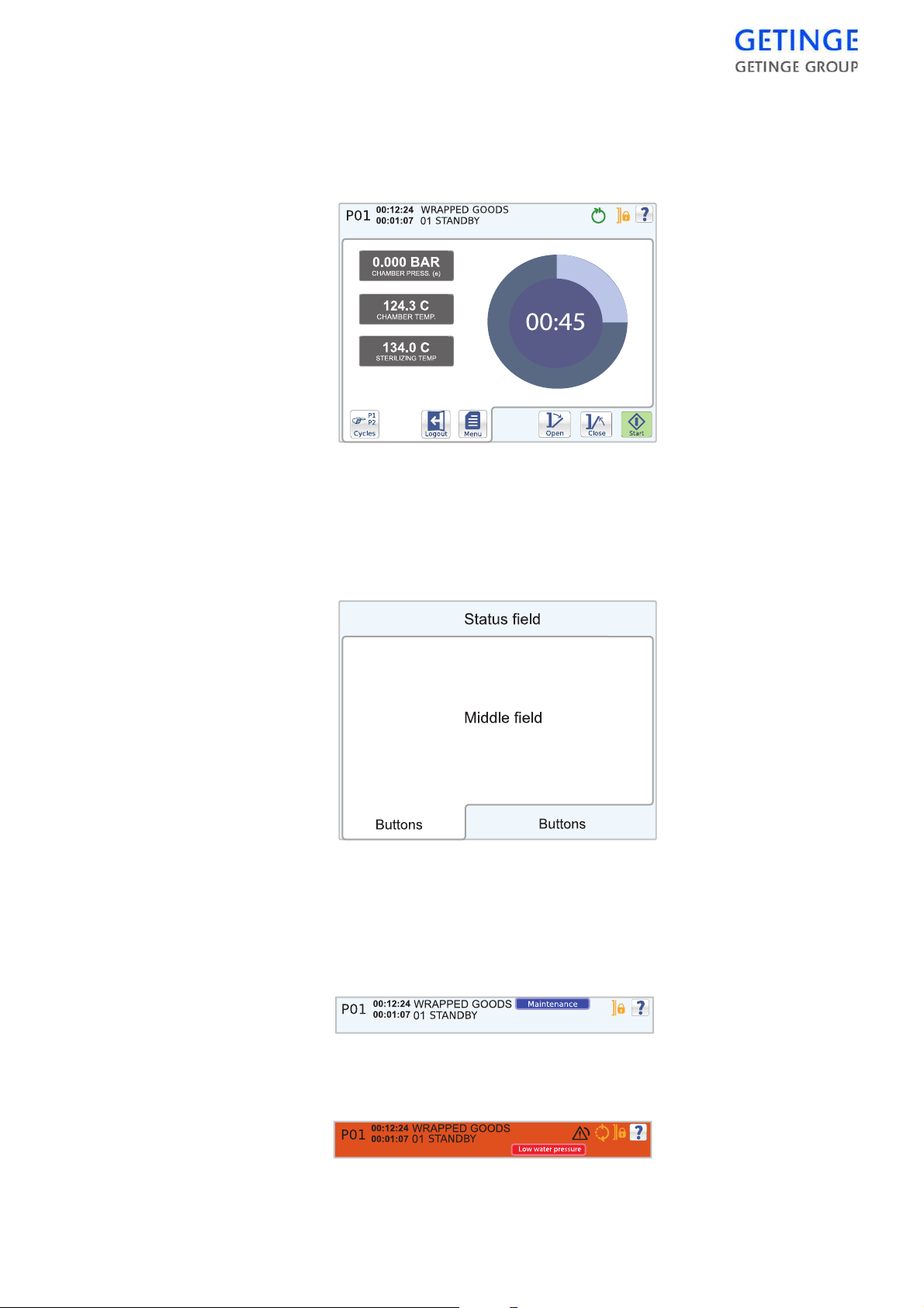
Screen
The screen can be divided into three areas: status field, middle field and
button field.
Status field
The status field is displayed in all cycle images. The field contains
information about the machine's current status, such as the current cycle
and phase and the time these have lasted. The message is displayed in a
blue box to the left of the indicators.
In the event of an alarm, the status field color changes to red and an error
message displays in a red message box to the left of the indicators.
CONTROL UNIT -
51

Middle field
The middle field is specific for the screen and displays unique functions
and information for the respective menus; see the section Screens i n the
Main Menu chapter.
Button field
The button field shows the application buttons that are used to give
commands.
52 -
CONTROL UNIT

Buttons and symbols
Symbol Operation Description
Indicators Doors locked The machine’s doors are closed
and locked.
Doors closed The doors of the machine are
closed.
Cycle in progress The machine is processing the
selected cycle.
Completed cycle Steady light: Normal cycle
concluded without warnings or
errors.
Flashing light: Test cycle
concluded without warnings or
errors.
Completed cycle Steady light: Cycle concluded, but
a warning and/or error has arisen
during processing.
Flashing light: Test cycle
concluded, but a warning and/or
error has arisen during processing.
Alarm Solid light until the process reaches
"Stand by". Only then can the
alarm be acknowledged by
pressing a button.
CONTROL UNIT -
53
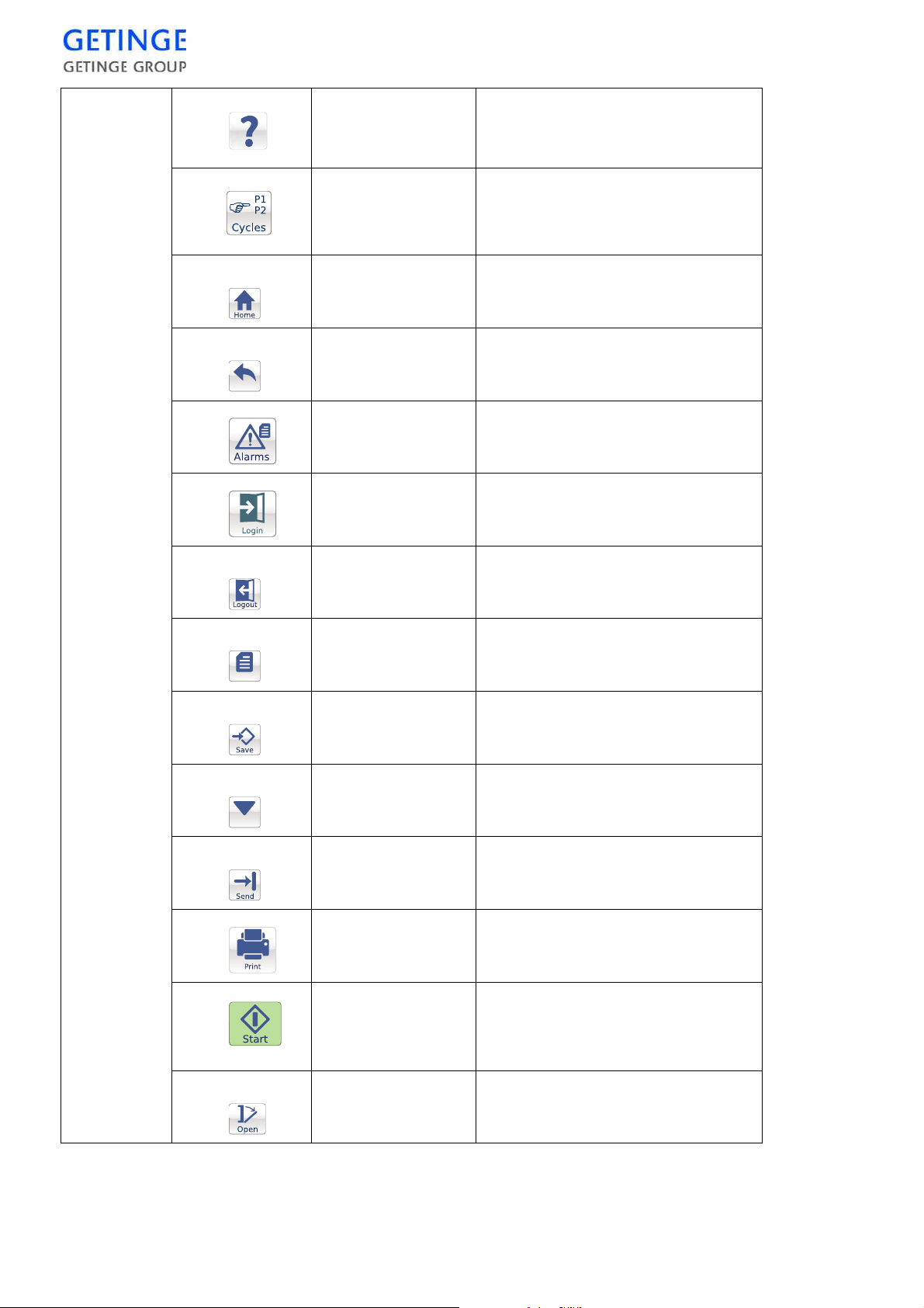
Buttons
Help
No function. For information, see
"User Manual" or "Service
manual."
Back
Cycles
Home
Back
Alarm
Login
Logout
Open menu to select cycle.
Note: Not displayed on the
unloading side.
Display latest start screen.
Return to the previous window or
menu, or undo the input.
Display menu for alarm history.
Display login screen.
Log out current user.
Menu
Calibrate
Menu
Save
Calibrate
Submit
Print
Start
Return to the main menu.
Save edited data.
Execute calibration.
Submit values to the PACS.
Send selected data to the printer.
Start the selected cycle.
Note: Not displayed on the
unloading side.
54 -
CONTROL UNIT
Open
Open machine door.

Close
Close machine door.
Alarmhandling
Information
Other
points
More
Optional when alarms or
preprogrammed functions are
active.
Silence alarm
signal
Cycle
information
Switch alarm signal off.
Provides information about
current process and phase, as well
as the time these have been going
on for. The information is
displayed on the top left.
Messages Displayed if an incident occurs.
The message is displayed in a blue
text box on the left of the
indicators.
Save
Save changes and inputted values.
Numeric keyboard
Alphabetic
keyboard
Right
and
left
arrow
Zoom in/out
Insufficient user
access
Shift from alphabetic to numeric
keyboard.
Shift from alphabetic to numeric
keyboard.
Move the cursor in the input
window.
Enlarge/reduce plot graph.
No authorization for accessing the
menu.
CONTROL UNIT -
55

Scroll list If there are more rows than space
The various states of the buttons
Active The button can be pressed
Pressed The button is pressed.
Not available If the symbol remains, the button is currently not
available.
available on the screen , a scroll list
is displayed on the right. To reach
the row above or below, just drag
the button.
Boot screen
Ready to start The cycle can be started.
When the panel starts, the screen below displays. The blue bar moves
from left to right. When the panel is ready and the control system is
ready, the panel automatically switches to the pie chart screen.
56 -
CONTROL UNIT
In case of communication errors between the panel and the operatin g
system, the blue bar travels back and forth. There is no communication
with the operating system as long as this screen displays and no
command can be sent to the operating system.
Call a service technician.

Pop-up windows and dialogue windows
Alarm pop-ups
Shown below is an example of an alarm pop-up.
In the event of an alarm, the current alarm displays as a pop-up window
on the screen and an alarm sounds. For alarm management, see the
"Alarm" section in the chapter Operation of the USER MANUAL.
Information pop-ups
Displayed below is an example of an information pop-up.
The information is displayed on th e screen. P ress the button to return to
the previous procedure screen.
Dialogue window
Shown below is an example of a dialogue pop-up.
CONTROL UNIT -
57

The window remains on the screen until a selection is made by pressing
the desired button.
Green information window
The window and an acknowledgement button lights up to signal that the
process is ready.
An audible signal sounds.
The window remains on the screen until the acknowledgemente button
is pressed or the door is opened automatically.
58 -
CONTROL UNIT

Inputting window
.
Here are two examples of inputting windows.
To enter a name, press the desired letters.
To toggle between small and capital letters, click the arrow up button
down to the left.
To switch to a numeric keyboard, press the button with numbers at the
bottom left.
Press
Save
furthest to the right to save the entry.
To edit the time, mark the number you wish to edit using the arrow keys
at the bottom. Press the desired number. To save the entry, press
Save
at the bottom right.
Different inputting windows exist depending on the input data required.
CONTROL UNIT -
59
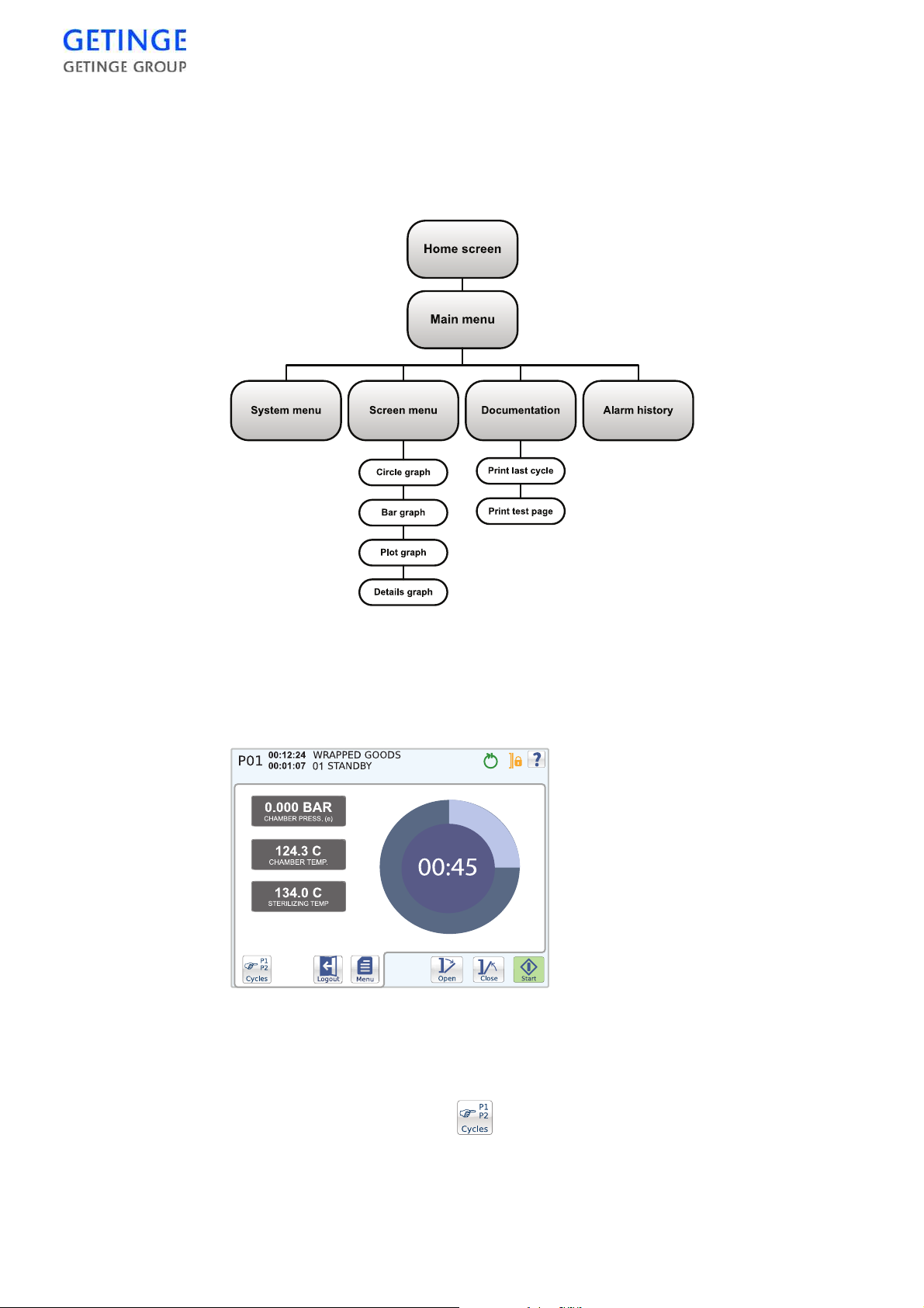
Operator menu Avanti
Description of menus and functions
Start screen
The start screen allows access to the main functions for starting a cycle.
Open/Close door.
The door is opened and close d with the
Open
and
Close
buttons,
respectively.
Cycle selection
Cycles are selected with the button in the bottom left corner of
the button field.
60 -
CONTROL UNIT
A list of optional cycles is shown.

To select a cycle, press t he desired cycle. The previous screen is
displayed again.
The selected cycle is displayed in the top left corner of the status field.
Note! The function is not available from the unloading side.
Start cycle
Selected cycles are started with the
Start
button. If the sterilizer is not
ready to start, a message is shown.
Note! The function is not available from the unloading side.
Various information about the current cycle is displayed depending on
the current start screen. For further information, see the Screens section
in Main menu.
The length of time that the cycle or current phase has been running is
displayed in the status field. Also displayed here is the current cycle
indicator.
Login/logout
•
To log in, mark
Login
. An inputting window is displayed for
inputting the password.
Main menu
•
Because a user is already logged in, the
Logout
button is displayed
instead. This logs out the current user.
•
Typing in an incorrect password brings up an information window.
Press the
•
If an incorrect password is entered on login when starting the cycle,
Back
button to return to the data entry window.
the panel returns to the previous menu after one minute.
The
Menu
button returns you to the main menu.
System menu
About
A list of machine specific data is displayed.
CONTROL UNIT -
61

The following information is displayed:
•
Machine name
•
Application version
•
Panel version
•
PACS version
•
PROM date
•
Serial number
•
Total amount of cycles
Other menus require a password and are described in the Service
Manual.
Screens
Circle graph
The start screen shows a pie chart and three cycle parameters.
The pie chart graphically displays the time remaining for the cycle. The
circle diagram also displays the time remaining in digit form.
The following cycle parameters are displayed:
•
Current chamber pressure
•
Current chamber temperature
•
Sterilization temperature for the selected cy cle
Bar graph
The start screen displays two cyc le parameters, as well as a ba r graph
for the respective parameters and cycle time remaining.
62 -
CONTROL UNIT
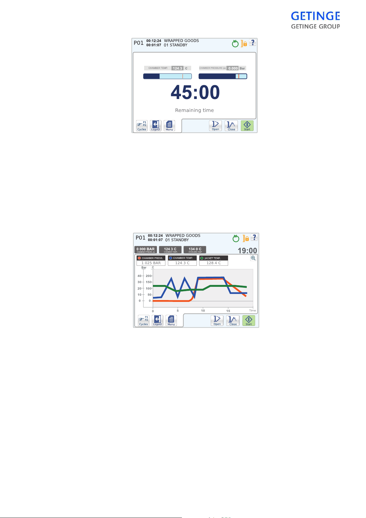
The following cycle parameters are displayed:
•
Current chamber temperature
•
Current chamber pressure
Plot graph
The start screen displays a plot graph with various cycle parameters.
The status field also shows other cycle parameters. The remaining cycle
time is displayed to the right in the status field.
The following cycle parameters are displayed in the status field:
•
Current chamber pressure
•
Current chamber temperature
•
Sterilization temperature for the selected cycle
The following cycle parameters are displayed as graphs:
•
Current chamber pressure
•
Current chamber temperature
•
Current jacket temperature
CONTROL UNIT -
63
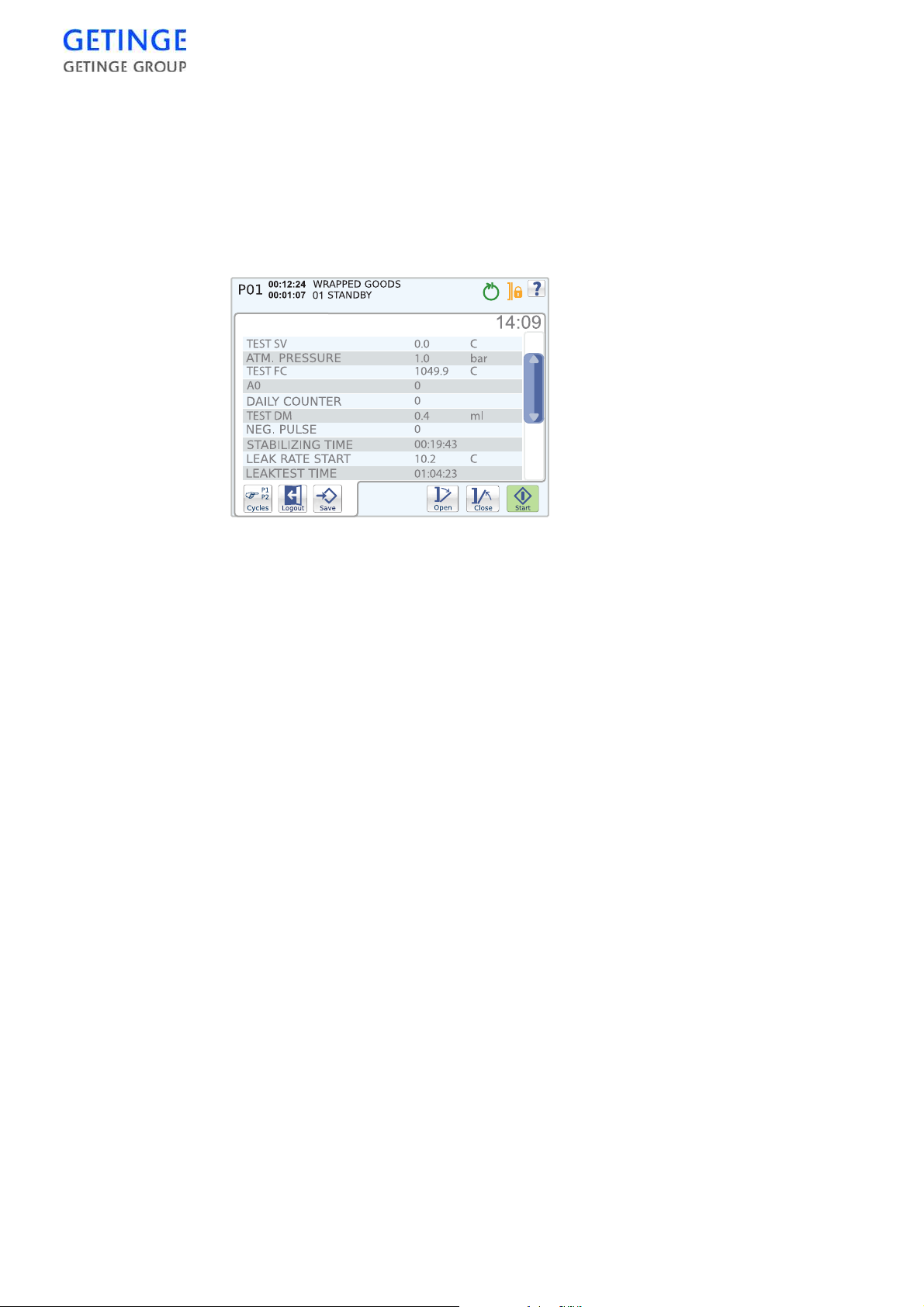
In order to enlarge the graph, press
Zoom in
. When the graph is enlarged
it is possible to navigate by pressing somewhere on the screen and then
dragging with a finger.
Details Graph
The start screen displays a list of parameters that shows information
about the system and the current cycle. The rema ining cycle time is
displayed on the top right-hand side, above the list.
Documentation
An pull-down menu with optional pr intout modes is displayed. The
possibility of choosing printouts varies depending on the user.
The following printout modes exist:
•
Print last cycle, latest cycle run.
•
Print alarm list, list of the most recent alarms. Password required.
•
Print cycle
A list of optional print cycles is displayed. To print, select the print
cycle of your choice and press
•
Print test page
•
Print all cycles. Password required.
•
Print machine setup. Password required.
Printout
. Password required.
Note! It is not possible to print during the current cycle.
Alarm history
A list of the last 20 alarms is displayed.
For more detailed information about an alarm, press the alarm you wish
to select.
64 -
CONTROL UNIT

The following alarm information is displayed:
Error Description of the alarm.
Date The date when the alarm triggered.
Time The time when the alarm triggered.
Phase The phase that was current when the alarm triggered.
Sub-phase The sub-phase that was current when the alarm
triggered.
Cycle time Specifies how long the cycle had been going on when
the alarm triggered.
Reset counter The number of cycles executed when the alarm
triggered.
CONTROL UNIT -
65

66 -
CONTROL UNIT
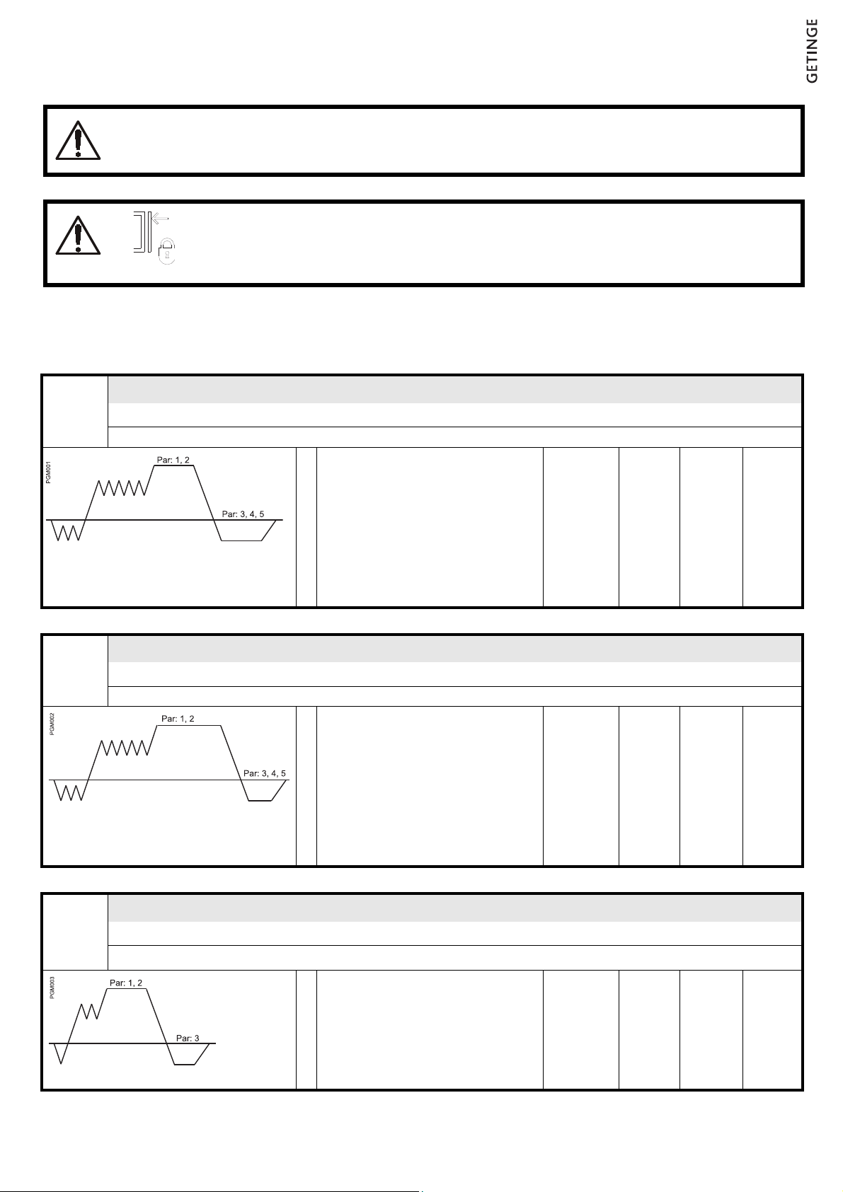
Program combination 2530290-090
Liquids must not be processed with any of these programs.
Hazardous waste and explosive materials must not be processed in this sterilizer.
Door blocking key
The door does not close when the key is in the locked position and the door is in open
position, as indicated by the symbol. When entering or cleaning the chamber the key
must be removed from the locking device.
P 0 1 Wrapped goods, textiles, porous load
RAX2000
Parameter Range Delivered Actual
Negative pulses - - - 3 3 ................
Positive pulses - - - 5 5 ................
1 Sterilizing temperature °C 134 134 ................
2 Sterilizing time min 3 - 7 4 ................
3 Postvacuum time min 0 - 90 5 ................
4 Postpuls steam - - - 0 - 25 0 ................
5 Postpuls air - - - 0 - 25 0 ................
P 0 2 Wrapped, heat sensitive material, rubber, plastic, porous load
RAX2001
Parameter Range Delivered Actual
Negative pulses - - - 3 3 ................
Positive pulses - - - 5 5 ................
1 Sterilizing temperature °C 121 121 ................
2 Sterilizing time min 16 - 20 16 ................
3 Postvacuum time min 0 - 90 5 ................
4 Postpuls steam - - - 0 - 25 0 ................
5 Postpuls air - - - 0 - 25 0 ................
P 0 3 Rapid process for single, open instrument
RAX2002
Password required!
Parameter Range Delivered Actual
Negative pulses - - - 1 1 ................
Positive pulses - - - 2 2 ................
1 Sterilizing temperature °C 134 134 ................
2 Sterilizing time min 3 - 90 4 ................
3 Postvacuum time min 0 - 90 3 ................
B3111_Rev 2

P 0 4 Bowie & Dick test
RAX2003
Password required!
Parameter Range Delivered Actual
Negative pulses - - - 3 3 ................
Positive pulses - - - 5 5 ................
1 Sterilizing temperature °C 121 - 135 134 ................
2 Sterilizing time min 0 - 15 1 ................
3 Postvacuum time min 0 - 90 3 ................
P 05 Automatic leak rate test
RAX2004
Password required!
Parameter Range Delivered Actual
1 Stabilizing time min 10 - 90 10 ................
2 Test time min 10 10 ................
B3111_Rev 2


Print date 2014-06-30
 Loading...