

AX4 / AX10 / AX14
A
X
4
/0
1
Éclairage Opératoire
Surgical Lighting System
OP-Leuchten
Notice Technique
Technical Manual
Technische Anleitung
AX/NTC/03/00 Réf. 010733103 Edition 03
Éclairage opératoire
Surgical lighting system
OP-Leuchten
EXIGENCES QUALITE
Certification du système qualité de
lentreprise A.L.M.
LAFAQ et le G-MED attestent que le
système adopté par ALM pour la
conception et la réalisation des tables
dopérations et des éclairages
opératoires, a été évalué et jugé
conforme aux exigences des normes
ISO 9001. Version 1994 (Cetificat
AFAQ n°1989/032) et EN-46001
Version 1994 (Certificat G-MED
n° 0222/46001/1).
La norme EN-46001 constitue le
nouveau référentiel européen
d'assurance qualité pour les fabricants
de matériel médical.
Marquage CE
L'éclairage PRISMALIX appartient à la
classe I et satisfait aux dispositions du
décret n° 95-292 du code de la santé
publique (Annexe VII de la directive
93/42/CEE du 14.06.1993 relative
aux dispositifs médicaux) qui lui sont
applicables.
QUALITY COMPLIENCE
Certification of ALM quality system.
AFAQ and G-MED certify that the
system implemented at ALM for
design and production of operating
tables and surgical lights complies
with the requirements of standard ISO
9001.
Version 1994 (AFAQ certificate
No. 1989/032) and EN-46001 Version
1994 (G-MED Certificate No. 0222/
46001/1).
The standard EN-46001 is the new
European quality assurance baseline
for medical equipment manufacturers.
EC marking
The PRISMALIX surgical light is part
of class I and satisfies the provisions
of decree No. 95-292 of the public
health code (Appendix VII of directive
93/92/EEC dated 14/06/1993 relative
to medical equipment) as may be
applicable.
QUALITÄTSANFORDERUNGEN
Zertifizierung des QM-Systems von A.L.M.
Die AFAQ und G-MED bescheinigen, das
System von A.L.M. für den Entwurf und
die Herstellung der OP-Tische und OP-
Leuchten bewertet und die
Übereinstimmung mit den Anfor-derungen
der Normen ISO 9001, Fassung 1994
(AFAQ-Zertifikat Nr. 1989/032) und EN-
46001, Fassung 1994 (G-MED-Zertifikat
Nr.0222/46001/1) positiv beurteilt zu
haben.
Die Norm EN-46001 ist für die Hersteller
medizinischer Geräte das neue europäische Bezugssystem für Qualitätssicherung.
EG-Zeichen
Die Leuchten PRISMALIX gehört zur
KlasseI und entspricht den für diese
Klasse geltenden Bestimmungen des
Erlasses Nr.95-292 des Gesetzbuches
für öffentliche Gesundheit (Anhang VII
der Richtlinie 93/42/EG vom 14.06.1993
für medizinische Geräte)
Certification des produits A.L.M.
L'éclairage PRISMALIX a été conçu en
conformité avec les normes
internationales IEC 601-1
(EN 60-601-1) ainsi quavec le projet
de norme particulière
IEC 601.2.41 .
La gamme de coffrets dalimentation
"ENERGIX WPS" a été conçue en
conformité avec les standards
suivants :
- IEC 601/1,
- UL 2601,
- IEC 601/1/2,
- FCC part 15,
- IEC 1000-3-2.
Certification of ALM products
The PRISMALIX surgical light is
designed in compliance with
international standards IEC 601-1
(EN 60-601-1) and with specific draft
standard IEC 601.2.41.
The "ENERGIX WPS" power supply
units are designed in compliance with
the following standards:
- IEC 601/1,
- UL 2601,
- IEC 601/1/2,
- FCC part 15,
- IEC 1000-3-2.
Zertifizierung der Erzeugnisse von A.L.M.
Die Leuchten PRISMALIX wurde in
Übereinstimmung mit den internationalen
Normen IEC601-1 (EN60-601-1) sowie
mit der Sondervornorm IEC601.2.41
entworfen.
Das Angebot der Stromversorgungsgerät
«ENERGIX WPS» wurde in Übereinstimmung mit folgenden Standards
entworfen:
- IEC 601/1,
- UL 2601,
- IEC 601/1/2,
- FCC Teil 15,
- IEC 1000-3-2
010733103-3
2
010733103 Notice technique / Technical manual / Technische Anleitung

Éclairage opératoire
Surgical lighting system
OP-Leuchten
SOMMAIRE
Exigences qualité .................... 2
Garantie ................................... 4
1 - Réglage des bras ressort
AX10 / AX14 et AX4 ................. 7
2 - Réglage du débattement .... 7
3 - Les 4 clés de maintenance 9
4 - Nettoyage interne du
projecteur AX4....................... 11
5 - Procédure de réglage des
miroirs d'AX4 ......................... 13
6 - Nettoyage interne du
projecteur AX10 ..................... 15
CONTENTS
Quality complience............... 2
Warranty .................................. 4
1 - Adjustment of AX10 / AX14
and AX4 spring arms .............. 7
2 - Maximum height
adjustment .............................. 7
3 - The 4 maintenance keys .... 9
4 - Internal cleaning of AX4
lighthead ................................ 11
5 - Adjustment procedure for
the AX4 mirrors ..................... 13
6 - Internal cleaning of AX10
lighthead ................................ 15
INHAL T
Qualitätsanforderungen ...... 2
Garantie .................................. 4
1 - Einstellung der Federarme
AX10 / AX14 y AX4.................. 7
2 - Einstellung der
Schwenkung .......................... 7
3 - Die 4 Schlüssel zur
Wartung ................................. 9
4 - Innenreinigung der AX4-
Operationsleuchten .............. 11
5 - Einstellungsverfahren der
AX4-Spiegel ........................... 13
6 - Innenreinigung der AX10-
Operationsleuchten .............. 15
7 - Nettoyage interne du
projecteur AX14 ..................... 17
8 - Procédure de réglage des
miroirs d'AX14 ....................... 19
9 - Changement des douilles
sur le bloc optique ................ 23
10 - Nomenclatures et
planches ................................ 25
Interventions spécifiques ..... 64
7 - Internal cleaning of AX14
lighthead ................................ 17
8 - Adjustment procedure for
the AX14 mirrors ................... 19
9 - Replacement of the plugs on
the optical bloc ...................... 23
10 - Parts lists and
drawings ................................ 25
Specific interventions ........... 64
7 - Innenreinigung der AX14-
Operationsleuchten .............. 17
8 - Einstellungsverfahren der
AX14-Spiegel ......................... 19
9 - Auswechseln der Buchsen
auf dem optischen Block ...... 23
10 - Stückliste und
Zeichnungen ......................... 25
Spezifische Eingriffe ............ 64
010733103-3
Notice technique / Technical manual / Technische Anleitung
010733103
3
Éclairage opératoire
Surgical lighting system
OP-Leuchten
GARANTIE
ALM garantit le matériel fourni contre tout
défaut de matière ou de fabrication pendant
une période de 24 mois à dater de sa réception et au plus tard 30 mois après livraison
dans les conditions contractuelles, à l'exception des caméras (12 mois).
La garantie ne couvre que les fournitures
dALM.
Elle est limitée au remplacement des pièces
reconnues défectueuses. Les frais de maind'oeuvre, de séjour et d'assurance du personnel
chargé d'effectuer le remplacement des pièces
reconnues défectueuses sont tous à la charge
du client.
Toute pièce remplacée deviendra la propriété
d'ALM et devra lui être retournée dans le mois de
son remplacement, faute de quoi ALM se réserve le droit de facturer la valeur de la pièce
remplacée.
Les interventions effectuées sous garantie n'entraînent pas de prolongation du délai initial de
garantie.
Cette garantie ne s'applique toutefois pas
aux pièces d'usure normale et aux consommables (en particulier ampoules,
fusibles, porte ampoule, poignée
stérilisable etc...)
Pour bénéficier de la garantie, l'acheteur doit
prévenir par lettre, ou télécopie confirmé par
lettre, de tout défaut dans les 3 jours au plus tard
après sa constatation.
L'acheteur doit présenter à ALM toutes les
preuves démontrant que la défaillance incombe
à ALM et donner toute facilité à ALM pour
procéder à leur constatation. ALM conseille
l'achat par le client de pièces de rechange et ce,
en même temps que le matériel proposé.
ALM pourra utiliser les pièces de rechange
existantes chez l'acheteur sous réserve de les
remplacer.
ALM fournira sur demande aux techniciens
dûment accrédités les principaux schémas électriques et nomenclatures.
La garantie disparaît si les fournitures ont fait
l'objet de modifications ou réparations effectuées par l'acheteur ou des tiers sans l'accord
écrit préalable dALM.
Cette garantie exclut tout versement d'indemnités.
Les engagements de cette garantie sont personnels à l'acheteur et cessent dès l'instant où
il cède le matériel.
La garantie ne couvre pas :
Les incidents tenant à des cas fortuits ou
de force majeure tels que décrits à l'article
X des conditions générales de vente,
Les réparations ou remplacements imposés
par l'usure normale du matériel,
Les détériorations ou accidents provenant
du fait du client tels que négligence, défaut
de surveillance, erreurs de branchement,
inobservation des consignes de mise en
service ou dentretien, utilisation anormale
provenant notamment de surcharges de toute
sorte.
La garantie ne s'applique plus lorsqu'une
ampoule autre que celle proposée par ALM
est utilisée.
WARRANTY
ALM warrants the equipment against all material
or manufacturing defects for a period of 24
months after shipment or a maximum of 30
months after delivery in accordance with the
contract, whichever period ends first. Cameras
systems have a 12 months warranty only.
The warranty covers ALM-supplied equipment
only.
The warranty is limited to replacement of parts
acknowledged to be defective. The labor,
travel, living and insurance expenses of the
crew replacing parts acknowledged to be
defective are the responsability of the customer.
Title to replaced parts shall revert to ALM
and these parts shall be returned to ALM
within one month of replacement; otherwise
ALM reserves the right to charge the customer
for the replaced part.
Repairs performed under warranty do not
extend the initial warranty period.
This warranty does not cover the normal wear
and tear of parts, nor does it apply to
consumables (in particular bulbs, fuses, bulb
holder, sterilizable handle, etc.).
To benefit from the terms of this warranty, the
Purchaser must inform ALM of any defect by
letter or by Fax followed by letter of confirmation
within 3 days of discovery of the defect.
The Purchaser shall provide ALM with all
evidence that the defect is incumbent on ALM
and provide ALM with every facility to
investigate the same. ALM recommends that
the customer purchase spare parts
simultaneously with the equipment.
ALM may use the Purchasers spare parts
subject to replacement thereof.
On request, ALM will supply the main
electrical diagrams and parts lists to the duly
accredited technicians.
The warranty shall not apply to any supplies
which have been altered or repaired by the
Purchaser or any other party without prior
written consent by ALM.
No damages are recoverable under this
warranty.
The obligations of this warranty shall apply to
the Purchaser only and cease to apply as of
disposal of the equipment to a third party by
the Purchaser.
The warranty does not cover:
+
Incidents caused by fortuitous events or
force majeure as described in article X of the
general conditions of sale.
Repair or replacement required due to
normal wear of the equipment.
Damage or accidents due to the customer
such as negligence, lack of supervision,
faulty installation, disregard of operating or
maintenance instructions, overload of any
kind due to improper usage...
Warranty shall no longer apply when bulb,
other than bulb proposed by ALM, is used.
GARANTIE
ALM gewährt auf die gelieferten Geräte
eine Garantie von 24 Monaten ab Empfang
und von höchstens 30Monaten nach
Lieferung unter Vertragsbedingungen für
Werkstoff- oder Herstellungsfehler,
abgesehen von den Kameras (12Monate).
Die Garantie betrifft ausschließlich die
Lieferungen von ALM.
Sie ist auf den Ersatz der als defekt
anerkannten Teile beschränkt. Die Lohn-,
Aufenthalts- und Versicherungskosten für
das mit dem Ersetzen der als defekt
anerkannten Teile beauftragten Personals
gehen alle zu Lasten des Kunden.
Ersetzte Teile werden zum Eigentum von
ALM und müssen in dem Monat, in dem sie
ausgewechselt werden, an ALM
zurückgesandt werden, mangels dessen sich
ALM das Recht vorbehält, den Wert des
ersetzten Teils in Rechnung zu stellen.
Die im Rahmen der Garantie durchgeführten
Eingriffe bewirken keine Verlängerung der
ursprünglichen Garantiedauer.
Diese Garantie gilt allerdings nicht für
normale Verschleißteile und
Verbrauchsmaterial (insbesondere Lampen,
Sicherungen, Lampenhalterungen,
sterilisierbare Griffe usw.)
Um die Garantie in Anspruch nehmen zu
können, muss der Käufer Mängel spätestens
innerhalb von 3Tagen nach der Feststellung
per Brief bzw. per Fax mit anschließender
brieflicher Bestätigung anmelden.
Der Käufer muss ALM alle Beweise vorlegen,
aus denen hervorgeht, dass der Mangel auf
ALM zurückzuführen ist und ALM die
Feststellung des Mangels möglichst
erleichtern. ALM empfiehlt den Kauf von
Ersatzteilen durch den Kunden gleichzeitig
mit den vorgeschlagenen Geräten.
ALM kann die beim Käufer vorliegenden
Ersatzteile benutzen, muss sie dem Käufer
aber ersetzen.
ALM verpflichtet sich, den geschulten
Technikern auf Anfrage die wichtigsten
Schaltpläne und Stücklisten zu liefern.
Die Garantie erlischt, wenn die Lieferungen
vom Käufer oder Dritten ohne die vorherige
schriftliche Zustimmung von ALM geändert
oder repariert wurden.
Die vorliegende Garantie schließt die Zahlung
von Entschädigungen aus.
Die vorliegenden Garantieverpflichtungen
sind persönlich an den Käufer gebunden und
werden bei Veräußerung oder Abtretung
des Gerätes ungültig.
Von der Garantie ausgeschlossen
++
sind:
Unvorhersehbare Zwischenfalle oder Fälle
höherer Gewalt, wie sie im ArtikelX der
allgemeinen Verkaufsbedingungen
beschrieben sind,
Reparaturen oder Ersatz aufgrund des
normalen Verschleißes der Geräte,
Beschädigungen oder Unfälle, die auf
den Kunden zurückzuführen sind, wie
Nachlässigkeit, mangelnde Überwachung,
falsche Anschlüsse, Verstoß gegen die
Vorschriften für Inbetriebnahme und
Wartung, Überlastungen aller Art,
insbesondere infolge unangemessener
Verwendung.
010733103-3
4
010733103 Notice technique / Technical manual / Technische Anleitung

Éclairage opératoire
Surgical lighting system
OP-Leuchten
010733103-3
Notice technique / Technical manual / Technische Anleitung
010733103
5
Éclairage opératoire
Surgical lighting system
OP-Leuchten
1 5 1 4
FIG. 3
8 9
5
7
6
5
6
FIG. 1 FIG. 2
6
010733103 Notice technique / Technical manual / Technische Anleitung
010733103-3

Éclairage opératoire
Surgical lighting system
OP-Leuchten
1 - REGLAGE DES
BRAS RESSORT
AX10 / AX14 ET AX4
AX 10 - AX 4
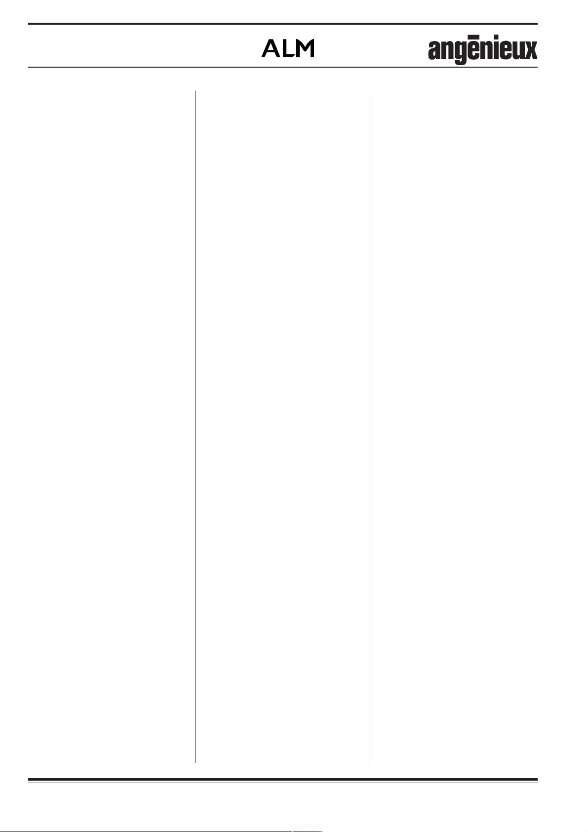
1) Retirer la vis (5) et le cache (6)
(FIG. 1).
AX 14
1) Retirer les 2 vis (15) et les 2 caches
(14) (FIG. 3)
2) Amener le bras ressort à lhorizontale jusquà voir la bague à trous
apparaître dans louverture.
3) (FIG. 2) A laide de la tige (7) de 4
mm de diamètre fournie avec le
bras, tourner la bague.
Sens (+) si la tête d'éclairage
tend à descendre.
Sens (-) si la tête d'éclairage tend
à monter.
1 - ADJUSTMENT OF
AX10 / AX14 AND AX4
SPRING ARMS
AX 10 - AX 4
1) Remove the screw (5) and cover
plate (6) (FIG. 1).
AX 14
1) Remove the 2 screws (15) and the
2 cover plates (14) (FIG. 3).
2) Place the spring arm in a horizontal
position until you see the ring with
the holes in the opening.
3) (FIG. 2) Use the 4 mm diameter rod
(7) (provided) to rotate the ring.
(+) If the lighthead tends to move
downward.
(-) If the lighthead tends to move
upward.
1 - EINSTELLUNG DER
FEDERARME
AX10 / AX14 Y AX4
AX 10 - AX 4
1) Die Schraube (5) und die Deckplatte
(6) entfernen (Abb.1).
AX 14
1) Die 2 Schrauben (15) und die 2
Deckplatten (14) entfernen (Abb.3).
2) Den Federarm in waagrechte Lage
bringen, bis der Ring mit den Löchern
in der Öffnung sichtbar wird.
3) Gemäß Abb.2 den 4 mm dicken
Stab (7) (mit den Arm geliefert)
benutzen, um den Ring zu drehen.
(+) wenn die Kuppel dazu neigt,
sich nach unten zu bewegen.
(-) wenn die Kuppel dazu neigt,
sich nach oben zu bewegen.
2 - REGLAGE DU
DEBATTEMENT
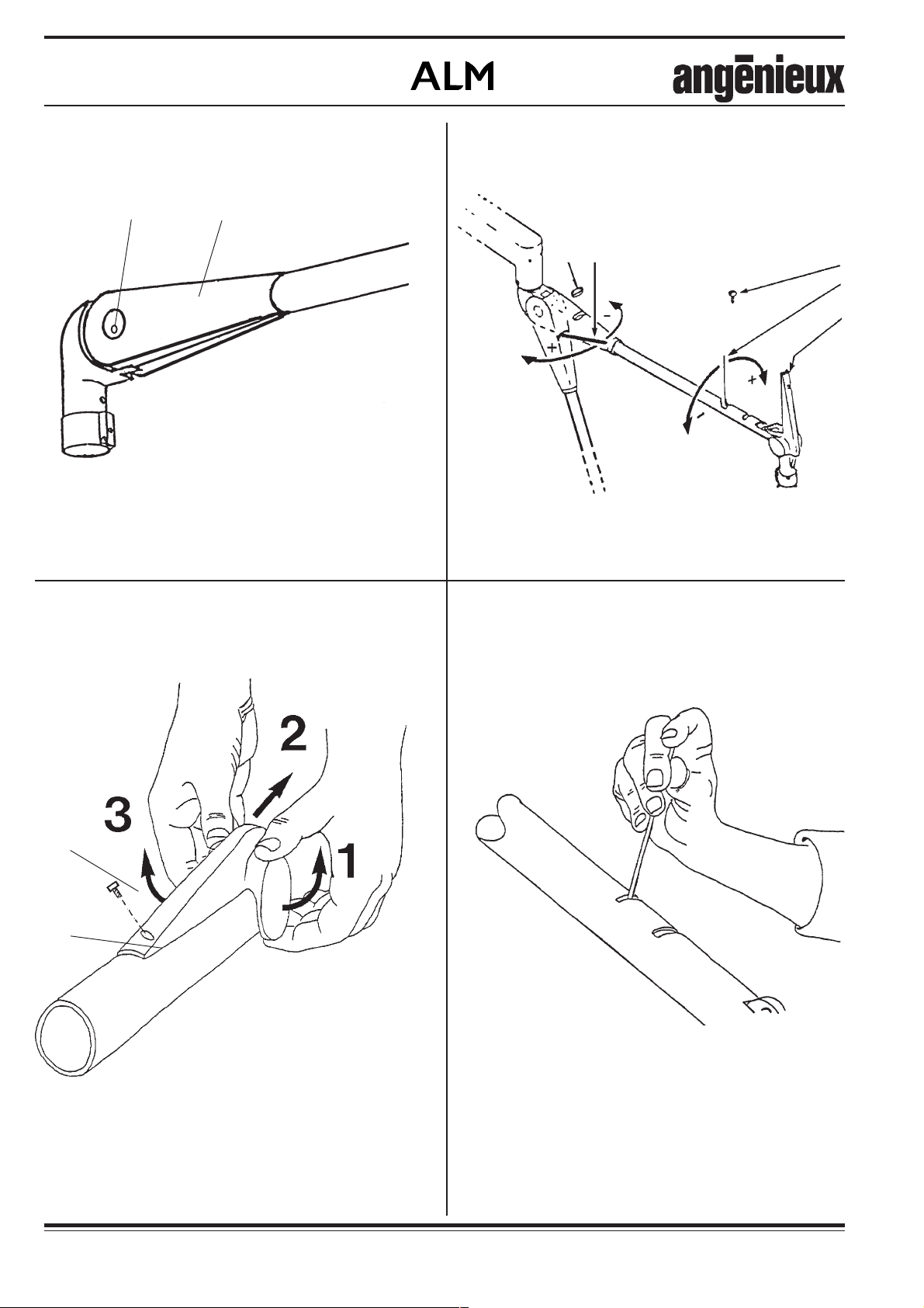
1) Enlever le couvercle (8) au moyen
dune tige de 4 mm de diamètre
placée dans lun des deux trous.
2) Abaisser le bras ressort jusquà voir
la bague à trous apparaître dans
louverture.
3) A laide de la tige (9) de 4mm de
diamètre, tourner la bague.
Sens (-) pour obtenir la course
maximale vers le bas.
Sens (+) pour obtenir la course
maximale vers le haut.
2 - MAXIMUM HEIGHT
ADJUSTMENT
1) Remove the cover (8) with the aid
of a 4 mm diameter rod placed in
one of the two holes.
2) Move the spring arm down until
you see the ring with the holes in
the opening.
3) Use the 4 mm diameter rod (9) to
rotate the ring.
(-) In order to obtain maximum
downward travel.
(+) In order to obtain maximum
upward travel.
2 - EINSTELLUNG DER
SCHWENKUNG
1) Mit Hilfe eines in einem der beiden
Löcher eingesetzten 4-mm-Stabs die
Abdeckung (8) entfernen.
2) Den Federarm so weit nach unten
bewegen, bis der Ring mit den
Löchern in der Öffnung erscheint.
3) Den 4 mm dicken Stab (9) benutzen,
um den Ring zu drehen.
(-) um den maximalen Weg nach
unten zu erhalten.
(+) um den maximalen Weg nach
oben zu erhalten.
010733103-3
Notice technique / Technical manual / Technische Anleitung
010733103
7

Éclairage opératoire
Surgical lighting system
OP-Leuchten
010733103-3
8
010733103 Notice technique / Technical manual / Technische Anleitung
Éclairage opératoire
Surgical lighting system
OP-Leuchten
3 - LES 4 CLES DE LA
MAINTENANCE
I. Serrage
- Alimentation électrique du projecteur, douilles sur
blocs optiques.
- Borniers de raccordement dans l'armoire de
commande.
II. Réglage
- Tension aux bornes des lampes en position maxi
du commutateur.
22,7 V + 0,5 pour l'AX14
23,3 V + 0,5 pour l'AX10
25,6 V + 0,5 pour l'AX4 70W
21,7 V + 0,5 pour l'AX4 150 W
- Focalisation : Tache ronde et homogène.
III. Contrôle
III.1. Points de sécurité
- Rigidité de la fixation.
- Serrage de l'écrou du monte et baisse.
- Présence de la vis à bout téton sur l'écrou du
monte et baisse.
- Appareils antérieurs à 1998, contrôler le serrage
des 3 vis à bout pointeau d'immobilisation de
l'écrou du monte et baisse.
- Serrage des vis et écrous d'assemblage des
sous-ensembles composants l'installation.
- Positionnement du circlips sur l'allonge des
suspensions compensées.
- Positionnement du secteur d'arrêt et de la bague
de retenue pour chaque projecteur.
- Fonctionnement sur secours (manuel par
bouton poussoir et automatique par coupure
secteur).
III.2. Autres contrôles
- Eclairement nominal à 1 m du projecteur en
position maxi du commutateur : 45 000 lux pour
AX4 70W.
60 000 lux pour AX4 150W hublots en verre
cathédrale.
80 000 lux pour AX4 150 W hublots micro
lentilles.
100 000 lux pour AX10 hublots en verre
cathédrale.
110 000 lux pour AX10 hublots micro lentilles.
120 000 lux pour AX14 hublots en verre
cathédrale.
130 000 lux pour AX14 hublots micro lentilles.
- Fonctionnement sur toutes les positions du
commutateur.
- Etat des supports de lampes et des lampes.
- Propreté interne : Blocs optiques, miroirs,
hublots.
A nettoyer une fois par an.
- Continuité des masses : 0,1 W maxi.
- Stabilité des projecteurs dans toutes les
positions.
- Régularité des couples de rotation, absence de
points durs.
- Tenue de la poignée stérilisable.
IV. Aspect
Nettoyage.
CONSOMMABLES
3 - THE 4 MAINTENANCE
KEYS
I. Tightening
- Light head power supply, plugs onto the optical
blocks.
- Electrical connections in the control box.
Il. Setting
- Voltage at the bulbs in maximum position of the
switch.
22,7 V + 0,5 for AX14
23,3 V + 0,5 for AX 10
25,6 V + 0,5 for AX4 70 W
21,7 V + 0,5 for AX4 150 W
- Focus: Patch circular and homogenous.
III. Control of working conditions
III .1. Safety checks
- Rigidity of the attachment.
- Tightening of the balance arm large nut.
- Presence of the safety screw on the balance arm
nut.
- Appliances prior to 1998, check the tightening of
the three immobilizing set screwsof the balance
arm large nut.
- Tightening of assembling screws of articulations.
- Correct position of the retaining ring on the
extender of the double spring arm suspension.
- Correct position of the securing clip and the
plastic ring.
- Stand by power (manual and autornatic).
III. 2. Others controls
- Nominal illumination at 1 m of the projector in
maximum position of the switch:
45 000 lux for AX4 70 W.
60 000 lux for AX4 150 W with glass ports.
80 000 lux for AX4 150 W with microlenses
ports.
100 000 lux for AX10 with glass ports.
110 000 lux for AX10 with microlenses ports.
120 000 lux for AX14 with glass ports.
130 000 lux for AX14 with microlenses ports.
- Working on all positions of the switch.
- Bulb holder and lamps.
- Internal cleaning, optical blocks, mirrors, glass
ports.
Cleaning, once a year.
- Ground continuity: 0,1 W maximum.
- Stability in all positions.
- Regularity in rotation torque.
- Sterilizable handle locking device.
IV - Appearance
- External cleaning.
EDIBLES
3 - DIE 4 SCHLÜSSEL ZUR
WARTUNG
I. Festigkeit
- Stromversorgung der Operationsleuchte,
Buchsen auf den optischen Blocks.
- Anschlussklemmen auf dem Bedienschrank.
II. Einstellung
- Spannung an den Glühlampenklemmen bei
Höchststellung des Schalters :
22,7 V + 0,5 an der AX14.
23,3 V + 0,5 an der AX10.
25,6 V + 0,5 an der AX4 70 W.
21,7 V + 0,5 an der AX4 150 W.
- Fokussierung : Runder und homogener Fleck.
III. Kontrolle
III.1. Sicherheitspunkte
- Steifheit der Befestigung.
- Festanzug der Mutter des Steig- und Neigsystems.
- Anwesenheit der Schraube mit Zapfen auf der
Mutter des Steig- und Neigsystems.
- Bei Maschinen der Baureihen vor 1998, überprüfung
der 3 Arretierschrauben der Mutter des Steig- und
Neigsystems.
- Festanziehen der Schrauben und Mutter, die zum
Zusammenbau der Unterbaugruppen der Installation dienen.
- Stellung des Sicherungsring des Ansatzstücks der
ausgeglichenen Aufhängungen.
- Stellung des Anschlag-bogenstücks und des
Rückhalterings für jede Operationsleuchte.
- Notfunktion (per Drucktaster und automatisches
Ausschalten).
III. 2.Andere Kontrollen
Spannung an den Glühlampenklemmen bei
Höchststellung des Schalters :
- Nennbeleuchtungwert bei Entfernung von 1 m der
Operationsleuchte, Schalter in Höchststellung:
45.000 Lux an der AX4, 70 W.
60.000 Lux an der AX4 150 W, Luken aus Katedralglases.
80.000 Lux an der AX4 150 W, Luken der Mikrolinsen.
100.000 Lux an der AX10, Luken aus Katedralglases.
110.000 Lux an der AX10, Luken der Mikrolinsen.
120.000 Lux an der AX14, Luken aus Katedralglases.
130.000 Lux an der AX14, Luken der Mikrolinsen.
- Funktionsweise in jeder Stellung des Schalters.
- Stabilität der Operationsleuchten in den gesamten
Stellungen.
Einmal im Jahr reinigen :
- Schutzleiter-Widerstands: Höchstens 0,1W.
- Innenreinigung: optischen Block, Spiegeln, Luken.
- Regelmäbige Umdrehung, Abwesenheit fester
Punkte.
- Halt der sterilisierbaren Griffs.
IV - Aussehen
- Aubenreinigung.
VERBRAUCHSMATERIALE
Type de Réf. Support Poignée
projecteur lampe lampe stérile
AX14 150W 24V 162798 187306
163508
AX10 100W 24V 162798 187306
186762
AX4 150W 150W 24V 162798 187306
163508
AX4 100W 100W 24V 162798 187306
010733103-3
186762
Notice technique / Technical manual / Technische Anleitung
Type of Bulb Bulbv Sterile
light Ref. holder handle
AX14 150W 24V 162798 187306
163508
AX10 100W 24V 162798 187306
186762
AX4 150W 150W 24V 162798 187306
163508
AX4 100W 100W 24V 162798 187306
186762
010733103
Typ Kennz. Leuchten- Sterilisierbaren
OP-Leuchten Leuchte Halterung Griff
AX14 150W 24V 162798 187306
163508
AX10 100W 24V 162798 187306
186762
AX4 150W 150W 24V 162798 187306
163508
AX4 100W 100W 24V 162798 187306
186762
9
Éclairage opératoire
Surgical lighting system
OP-Leuchten
010733003-11a
010733003-11a
FIG. 1
010733003-11c
010733003-11d
FIG. 3
010733003-11e
010733003-11f
FIG. 5
FIG. 2
FIG. 4
FIG. 6
10
010733003-11h
010733003-11g
FIG. 7
010733003-11j
010733103 Notice technique / Technical manual / Technische Anleitung
FIG. 9
FIG. 8
010733103-3

Éclairage opératoire
Surgical lighting system
OP-Leuchten
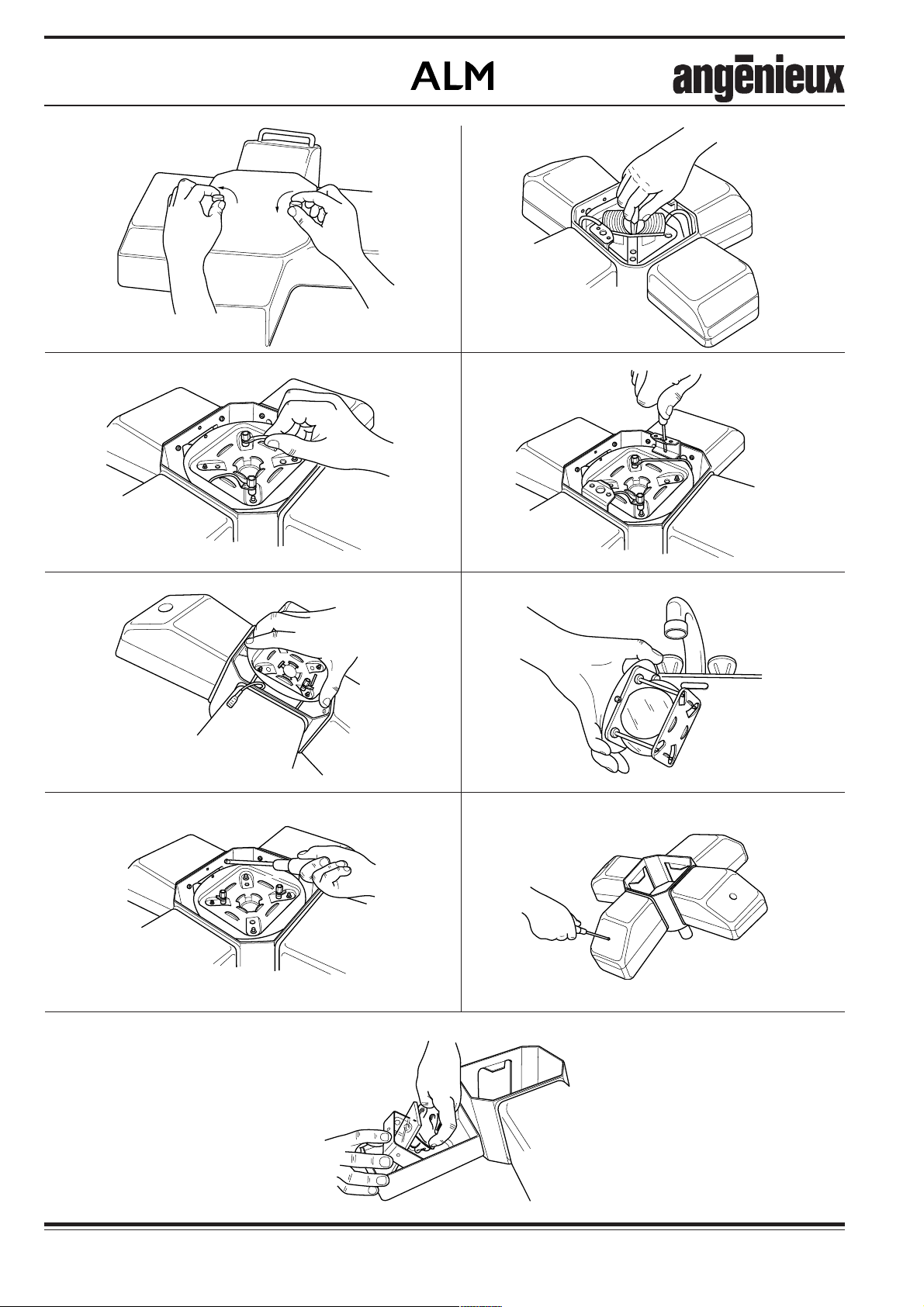
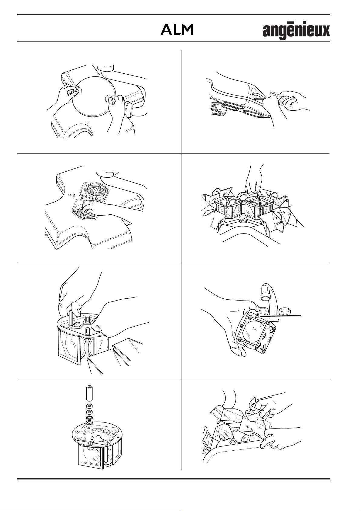
4 - NETTOYAGE INTERNE
DU PROJECTEUR AX4
1) Retirer le capot central (FIG. 1).
2) Retirer le support de lampe (FIG. 2).
3) Déconnecter les 2 fils sur le bloc
optique (FIG. 3).
4) Dévisser les 2 vis de maintien du
bloc optique et de fixation du système de fermeture du capot central
(FIG. 4).
5) Retirer le bloc optique.
ATTENTION : Repérer le sens de
montage (FIG. 5).
6) Passer le bloc optique sous l'eau
chaude ou le tremper dans l'eau
chaude, puis le sécher avec de l'air
comprimé (FIG. 6).
4 - INTERNAL CLEANING OF
AX4 LIGHTHEAD
1) Remove the central cover (FIG. 1).
2) Remove the bulbholder (FIG. 2).
3) Disconnect the 2 wires on the optical
block (FIG. 3).
4) Unscrew the 2 fixation screws of
the optical block and of the locking
system of the central cover (FIG. 4).
5) Remove the optical block.
CAREFUL: Check original positioning (FIG. 5).
6) Rinse the optical block under warm
water or dip it in a rinsing bath, then
dry it thanks to compressed air
(FIG. 6).
4 - INNENREINIGUNG DER
AX4-
OPERATIONSLEUCHTEN
1) Die zentrale Abdeckhaube entfernen
(Abb.1).
2) Die Lampenhalterung entfernen
(Abb. 2).
3) Beide Drähte vom optischen Block
abklemmen (Abb. 3).
4) Beide Schrauben die zum Halt des
optischen Blocks und zur
Befestigung des Verschlussystems
der zentrale Abdeckhaube dienen,
losschrauben (Abb. 4).
5) Den optischen Block entfernen.
ACHTUNG: Die Montageweise
merken (Abb. 5).
6) Den optischen Block unter warmes
Wasser halten oder ihn in warmes
Wasser tauchen und mit Druckluft
trocknen (Abb. 6).
7) Dévisser et ôter les 8 vis internes de
fixation de capots de bras ainsi que
les rondelles éventail (FIG. 7).
8) Dévisser les 4 vis externes de fixation des capots de bras (FIG. 8).
9) Nettoyer les miroirs et les hublots à
l'aide d'un chiffon doux légèrement
imbibé d'une solution alcoolisée à
moins de 20% (FIG. 9).
7) Unscrew and remove the 8 internal
fixation screws of the arm covers
(FIG. 7).
8) Unscrew the 4 external fixation
screws of the arm covers (FIG. 8).
9) Clean the mirrors and the ports
thanks a lintfree cloth and a 20%
solution of alcohol (FIG. 9).
7) Die 8 inneren Befestigungsschrauben der Armverkleidungen
losschrauben und mit den
Fächerscheiben herausziehen
(Abb. 7).
8) Die 4 äusseren Befestigungsschrauben der Armverkleidungen
losschrauben (Abb.8).
9) Die Spiegel und Luken mit einem
weichen Tuch, mit leicht
alkoholisiertem Mittel imprägniert
(höchstens 20 %), reinigen
(Abb. 9).
010733103-3
Notice technique / Technical manual / Technische Anleitung
010733103
11
Éclairage opératoire
3
3
Surgical lighting system
OP-Leuchten
1m
010733003-12a
FIG. 1
5
9
010733003-12b
FIG. 2
010733103-3
12
010733103 Notice technique / Technical manual / Technische Anleitung

Éclairage opératoire
Surgical lighting system
OP-Leuchten
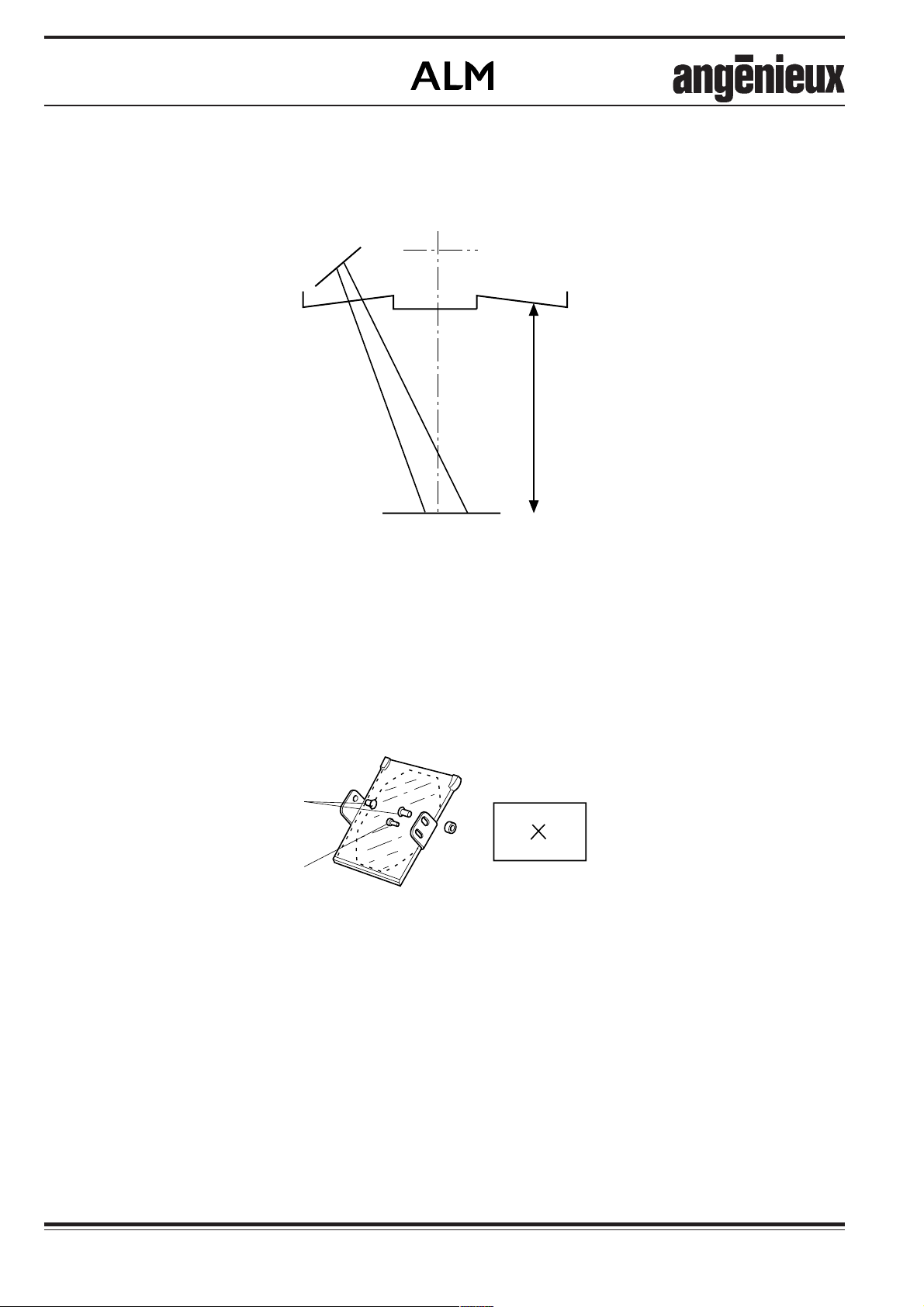
5 - PROCEDURE DE
REGLAGE DES MIROIRS
D'AX4
1) Retirer le capot central et les capots
de bras.
2) Vérifier que la lampe soit bien positionnée sur son support ainsi que le
support sur le bloc optique.
3) Positionner le projecteur à 1 m d'un
plan horizontal.
4) Eclairer le projecteur.
5) Tourner la poignée pour focaliser
les faisceaux au centre.
6) Déterminer le centre de la plage à
l'aide d'un fil à plomb et faire un
repère (FIG. 1).
7) Ne plus toucher à la poignée.
5 - ADJUSTMENT
PROCEDURE FOR THE AX4
MIRRORS
1) Remove the central cover and the
arm covers.
2) Check the position of the bulb on
the bulbholder and the bulbholder
on the optical block.
3) Place the lighthead at 1m from an
horizontal plane.
4) Light the projector.
5) Turn the handle in order to focus
the light beams at the center.
6) Determine the area center thanks a
plumb line and make a mark
(FIG. 1).
7) Do not touch the handle.
5 -
EINSTELLUNGSVERFAHREN
DER AX4-SPIEGEL
1) Die zentrale Abdeckhaube und die
Armverkleidungen entfernen.
2) Überprüfen, dass die Lampe richtig
im Sitz liegt und die
Lampenhalterung auf dem optischen
Block.
3) Die Operationsleuchte auf 1 m einer
waagerechten Ebene einstellen.
4) Die Leuchte einschalten.
5) Den Griff drehen bis dass die
Lichtbündel in der Mitte fokussiert
sind.
6) Die Mitte des Beleuchtungsbereichs
mit einem Senkblei bestimmen und
kennzeichnen. (Abb. 1).
7) Den Griff nicht mehr berühren.
8) Cacher 3 hublots à l'aide de caches
en carton.
9) Centrer chaque faisceau sur le repère du centre en agissant sur les
axes (35) et la vis (39) à l'aide de 2
clés plates de 10 mm et une clé
intravis de 2,5 mm (FIG. 2).
10) Répéter l'opération pour chaque
bras.
11) Enlever tous les caches et vérifier
que la plage soit homogène.
8) Hide 3 windows by means of
cardboard masks.
9) Center each beam onto the center
mark in aging onto the axes (35)
and the screw (39) thanks 2 flat
wrenches of 10 mm and an alen key
of 2,5 mm (FIG. 2).
10) Repeat the operation for each arm.
11) Remove all the masks and check
that the light patch is homogeneous.
8) 3 Luken mit Kartonabdeckungen
abdecken.
9) Jedes Lichtbündel auf dem
Kennzeichen feinstellen durch
Betätigung der Achsen (35) und der
Schraube (39). (zwei 10-mmSchlüssel und ein 2,5-mmInbusschlüssel) (Abb. 2).
10) Für jeden Arm, diesen Arbeitsschritt
wiederholen.
11) Die gesamten Kartonabdeckungen
entfernen und überprüfen, dass der
Beleuchtungsbereich homogen
ausfällt.
010733103-3
Notice technique / Technical manual / Technische Anleitung
010733103
13
Éclairage opératoire
Surgical lighting system
OP-Leuchten
010733003-14a
010733003-14c
FIG. 1
FIG. 3
010733003-14b
FIG. 2
010733003-14d
FIG. 4
14
010733003-14e
010733003-14f
010733003-11f
FIG. 5
FIG. 7
010733103 Notice technique / Technical manual / Technische Anleitung
010733003-14g
FIG. 6
FIG. 8
010733103-3

Éclairage opératoire
Surgical lighting system
OP-Leuchten
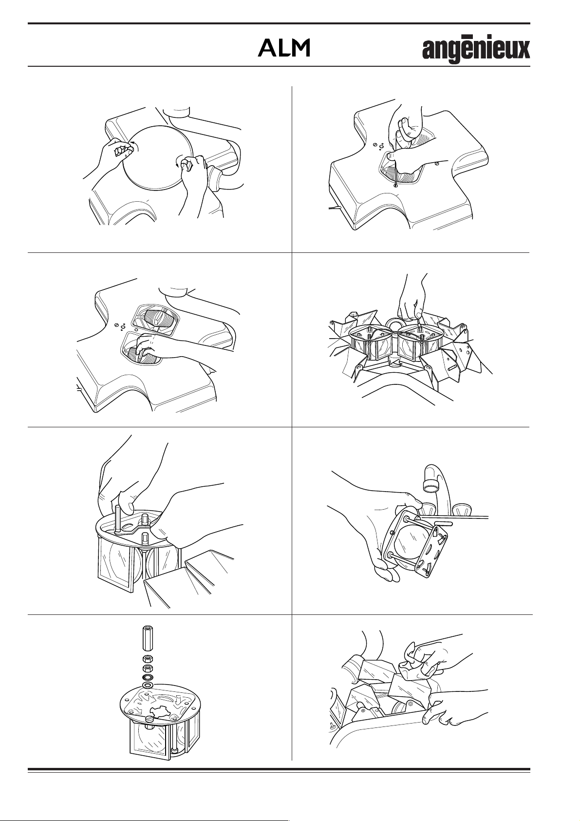
6 - NETTOYAGE INTERNE
DU PROJECTEUR AX10
1) Retirer le capot central (FIG. 1).
2) Dévisser les 4 vis situées sur la
partie supérieure du grand capot
ainsi que les 4 vis imperdables situées sur sa périphérie et retirer
celui-ci (FIG. 2).
Nettoyer un bloc optique à la fois.
3) Retirer le support de lampe (FIG. 3).
4) Déconnecter les 2 fils sur le bloc
optique (FIG. 4).
5) Repérer le hauteur des colonnettes
situées sur les tiges filetées de
maintien des blocs optiques puis
les dévisser, ôter les 4 écrous et
contre-écrous, ôter les 2 rondelles
éventail et les 2 rondelles de
centrage (FIG. 5).
6 - INTERNAL CLEANING OF
AX10 LIGHTHEAD
1) Remove the central cover (FIG. 1).
2) Unscrew the 4 screws located on
the top of the upper casing as also
that the4 screws located on it
periphery and remove it (FIG. 2).
Clean one optical block at a time.
3) Remove the bulbholder (FIG. 3).
4) Disconnect the 2 wires on the optical
block (FIG. 4).
5) Check the height of the columns
located on the threaded rods which
maintain the optical blocks and
unscrew them. Unscrew the 4 nuts
and counter nuts, remove the 2
notched washers and the 2
centering washers (FIG. 5).
6 - INNENREINIGUNG DER
AX10-
OPERATIONSLEUCHTEN
1) Die zentrale Abdeckhaube entfernen
(Abb.1).
2) Die 4 Schrauben oberhalb der gröberen
Abdeckung und die 4 unverlierbaren
Schrauben in seiner Nähe losschrauben.
Die Abdeckung herausnehmen. (Abb.
2)
Nacheinander die optischen Blocks
reinigen.
3) Die Lampenhalterung entfernen
(Abb. 3).
4) Beide Drähte vom optischen Block
abklemmen (Abb. 4).
5) Die Höhe der Säulen merken. Sie
befinden sich auf den
Gewindeschrauben, die zum Halt
des optischen Blocks dienen. Die
Säulen loschrauben : Die 4 Muttern
und Gegenmuttern, beide
Fächerscheiben und beide
Zentrierscheiben herausnehmen.
(Abb.5)
6) Retirer le bloc optique.
ATTENTION : Repérer le sens de
montage.
7) Passer le bloc optique sous l'eau
chaude ou le tremper dans l'eau
chaude, puis le sécher avec de l'air
comprimé (FIG. 6).
8) Repositionner le bloc optique sur
les 2 tiges filetées en veillant à ce
qu'il soit en appui correct sur son
support (FIG. 7).
- Remettre les rondelles de centrage
et éventail.
- Bloquer les 2 premiers écrous sur
les rondelles avec les doigts.
- Bloquer les contre écrous.
- Ajuster le hauteur des colonnettes
et les bloquer.
9) Recommencer ces opérations avec
le deuxième bloc optique.
6) Remove the optical block.
CAREFUL: Check original positioning.
7) Rinse the optical block under warm
water or dip it in a rinsing bath,
then dry it thanks to compressed air
(FIG. 6).
8) Put back the optical block in position on the 2 threaded rods and
check it is fixed properly on its
support (FIG. 7).
- Replace the centering washers and
the notched washers.
- Tighten the 2 nuts on the washers
with the fingers.
- Tighten the counter nuts.
- Adjust the height of the columns
and tighten them.
9) Repeat these operations with the
second optical block.
6) Den optischen Block entfernen.
ACHTUNG: Die Montageweise
merken (Abb. 5).
7) Den optischen Block unter warmes
Wasser halten oder ihn in warmes
Wasser tauchen und mit Druckluft
trocknen (Abb. 6).
8) Den optischen Block erneut auf beide
Gewindeschrauben einsetzen. Sich
vergewissern dass er richtig auf
seinem Halt sitzt (Abb. 7)
- Die Zentrier- und Fächerscheiben
erneut einlegen.
- Die 2 ersten Muttern mit den
Fingern auf die Scheiben setzen.
- Die Gegenmuttern festziehen.
- Die Höhe der Säulen ausrichten
und festziehen.
9) Diesen Arbeitsschritt erneut für den
zweiten optischen Block
durchführen.
10) Nettoyer les miroirs et les hublots à
l'aide d'un chiffon doux légèrement
imbibé d'une solution alcoolisée à
moins de 20% (FIG. 8).
010733103-3
Notice technique / Technical manual / Technische Anleitung
10) Clean the mirrors and the ports
thanks a lintfree cloth and a 20%
solution of alcohol (FIG. 8).
010733103
10) Die Spiegel und Luken mit einem
weichen Tuch mit leicht
alkoholisiertem Mittel imprägniert
(höchstens 20 %) reinigen
(Abb. 8).
15
Éclairage opératoire
Surgical lighting system
OP-Leuchten
010733003-17a
010733003-14a
010733003-14c
FIG. 1
FIG. 3
FIG. 2
010733003-14d
FIG. 4
16
010733003-14e
010733003-14f
010733003-11f
FIG. 5
FIG. 7
010733103 Notice technique / Technical manual / Technische Anleitung
010733003-14g
FIG. 6
FIG. 8
010733103-3

Éclairage opératoire
Surgical lighting system
OP-Leuchten
7 - NETTOYAGE INTERNE
DU PROJECTEUR AX14
1) Retirer le capot central (FIG. 1).
2) Dévisser les 8 vis imperdables et
retirer le grand capot supérieur
(FIG. 2).
Nettoyer un bloc optique à la fois.
3) Retirer le support de lampe (FIG. 3).
4) Déconnecter les 2 fils sur le bloc
optique (FIG. 4).
5) Dévisser les 4 écrous et contreécrous, ôter les 2 rondelles éventail
et les 2 rondelles de centrage
(FIG. 5).
6) Retirer le bloc optique.
ATTENTION : Repérer le sens de
montage.
7 - INTERNAL CLEANING OF
AX14 LIGHTHEAD
1) Remove the central cover (FIG. 1).
2) Unscrew the 8 screws and remove
the upper casing (FIG. 2).
Clean one optical block at a time.
3) Remove the bulbholder (FIG. 3).
4) Disconnect the 2 wires on the optical
block (FIG. 4).
5) Unscrew the 4 nuts and counter
nuts, remove the 2 notched washers
and the 2 centering washers
(FIG. 5).
6) Remove the optical block.
CAREFUL: Check original positioning.
7 - INNENREINIGUNG DER
AX14-
OPERATIONSLEUCHTEN
1) Die zentrale Abdeckhaube entfernen
(Abb.1).
2) Die 8 unverlierbaren Schrauben
losschrauben. Die grössere
Oberabdeckung (Abb. 2)
herausnehmen.
Nacheinander die optischen Blocks
reinigen.
3) Die Lampenhalterung entfernen
(Abb. 3).
4) Beide Drähte vom optischen Block
abklemmen (Abb. 4).
5) Die 4 Muttern und Gegenmuttern
losschrauben, beide Fächerscheiben
und beide Zentrierscheiben,
herausnehmen. (Abb.5)
6) Den optischen Block entfernen.
ACHTUNG: Die Montageweise
merken (Abb. 5).
7) Passer le bloc optique sous l'eau
chaude ou le tremper dans l'eau
chaude, puis le sécher avec de l'air
comprimé (FIG. 6).
8) Repositionner le bloc optique sur
les 2 tiges filetées en veillant à ce
qu'il soit en appui correct sur son
support (FIG. 7).
- Remettre les rondelles de centrage
et éventail.
- Bloquer les 2 premiers écrous sur
les rondelles avec les doigts.
- Bloquer les contre écrous.
9) Recommencer ces opérations avec
le deuxième bloc optique.
10) Nettoyer les miroirs et les hublots à
l'aide d'un chiffon doux légèrement
imbibé d'une solution alcoolisée à
moins de 20% (FIG. 8).
7) Rinse the optical block under warm
water or dip it in a rinsing bath,
then dry it thanks to compressed air
(FIG. 6).
8) Put back the optical block in position on the 2 threaded rods and
check it is fixed properly on its
support (FIG. 7).
- Replace the centering washers and
the notched washers.
- Tighten the 2 nuts on the washers
with the fingers.
- Tighten the counter nuts.
9) Repeat these operations with the
second optical block.
10) Clean the mirrors and the ports
thanks a lintfree cloth and a 20%
solution of alcohol (FIG. 8).
7) Den optischen Block unter warmes
Wasser halten oder ihn in warmes
Wasser tauchen und mit Druckluft
trocknen (Abb. 6).
8) Den optischen Block erneut auf beide
Gewindeschrauben einsetzen. Sich
vergewissern, dass er richtig auf
seiner Halterung sitzt (Abb. 7)
- Die Zentrier- und Fächerscheiben
erneut einlegen.
- Die 2 ersten Muttern mit den Fingern
auf die Scheiben setzen.
- Die Gegenmuttern festziehen.
9) Diesen Arbeitsschritt erneut für den
zweiten optischen Block
durchführen.
10) Die Spiegel und Luken mit einem
weichen Tuch mit leicht
alkoholisiertem Mittel imprägniert
(höchstens 20 %), reinigen (Abb.
8).
010733103-3
Notice technique / Technical manual / Technische Anleitung
010733103
17

Éclairage opératoire
010733003-18e
Surgical lighting system
OP-Leuchten
1
1m
010733003-18a
7
FIG. 1
010733003-18b
48
010733003-18d
45
44
46
47
FIG. 2
45
48
49
18
010733003-18c
FIG. 3
FIG. 4
010733103-3
010733103 Notice technique / Technical manual / Technische Anleitung

Éclairage opératoire
Surgical lighting system
OP-Leuchten
8 - PROCEDURE DE
REGLAGE DES MIROIRS
D'AX14
OUTILLAGE NECESSAIRE :
1 tournevis
1 mètre
13 caches en carton
1 luxmètre
2 clés plates de 10
1 clé alène de 2,5
1) Retirer le capot central n°1 (FIG. 1).
Dévisser les 8 vis imperdables n°7
du grand capot et les faire prendre
de quelques tours sur le capot.
Retirer le grand capot.
2) Positionner le projecteur à 1 m d'un
plan horizontal (FIG. 2).
Obturer les 12 hublots à l'aide de
cache en carton.
Vérifier le bon positionnement des
lampes sur leur support ainsi que
les supports sur leur bloc optique
respectif.
3) Mettre sous tension.
Optimiser la plage d'éclairement de
2 spots centraux en superposant le
mieux possible les plages correspondantes. On l'obtient en tournant chaque support de lampe de
180° ou en les changeant de bloc
optique (FIG. 3).
Avec la cellule du luxmètre, chercher le point où l'éclairement est le
plus élevé.
Pour la suite des opérations, ne plus
déplacer le cellule du luxmètre.
Obturer les 2 faisceaux centraux
avec des caches en carton.
8 - ADJUSTMENT
PROCEDURE FOR THE
AX14 MIRRORS
NECESSARY TOOLS:
1 screwdriver
1 measuring tape
13 cardboard masks
1 luxmeter
2 wrench lf 10mm
1 "Alen key" of 2.5mm
1) Remove the central cover nr 1
(FIG. 1).
Unscrew the 8 un loseable screws
nr 7 of the upper casing.
Remove the upper cover.
2) Position the projector at 1m from a
flat, horizontal, surface (FIG. 2).
Block the 12 windows with the
cardboard masks.
Check the positioning of the bulbs
on their support as well as of the
supports on their optical block.
3) Switch on the light.
Optimalize the illumination area
given by the 2 central spots over
laping as much as possible the
corresponding discrete patches. This
can be obtained by turning 180°
each lamp holder by placing them in
the opposite (FIG. 3)
Thanks to cell of the luxmeter
determine the brightest point and
do not move the cell until the full
completion of the adjustement
procedure.
Block the 2 central spots with the
cardboard masks.
8 -
EINSTELLUNGSVERFAHREN
DER AX14-SPIEGEL
NÖTIGE WERKZEUGE :
1 Schraubenzieher
1 Metermab
13 Sichtabdeckung aus Karton
1 Luxmeter
2 10-mm-Schlüssel
1 2,5 mm-Inbusschlüssel
1) Die zentrale Abdeckhaube entfernen
(Abb.1).
Die 8 unverlierbaren Schrauben Nr. 7
von der gröberen Abdeckung
losschrauben ; sie dann leicht anziehen
(Manuell, ein paar Mal die Schraube
drehen).
Die gröberen Oberabdeckung
herausnehmen.
2) Die Operationsleuchte auf 1 m einer
waagenrechten Ebene einstellen.
(Abb.2)
Die 12 Luken mit Kartonabdeckungen
abdecken.
Sich vergewissern, dass die Lampen
richtig auf deren Halterung sitzen und
deren Halterung auf dem optischen
Block.
3) Spannung einschalten.
Den Beleuchtungsbereich zweier
Mittelspots durch ein so gut wie
mögliches Überlagern der bezüglichen
Bereiche optimieren. Dies wird erreicht
durch eine 180°-Drehung der
Lampenhalterung oder wenn man sie
auf einem anderen optischen Block
setzt.
Den Höchsterleuchtungspunkt mit der
Luxmeterzelle ausfindig machen.
4) Régler chacun des 8 miroirs fixes
par centrage de leur faisceau respectif sur la cellule de luxmètre
(FIG. 4).
Procéder comme suit :
a) enlever le cache d'un hublot.
b) débloquer les écrous n° 45 et la
vis n° 46 à l'aide de 2 clés plates de
10 et d'une clé alène de 2,5.
c) centrer le faisceau sur la cellule.
d) rebloquer les écrous et vis.
e) remettre le cache sous le miroir
réglé.
f) répéter cette opération pour les 8
010733103-3
miroirs fixes.
Notice technique / Technical manual / Technische Anleitung
4) Focus individually the 8 fixed mirrors
on the luxmeter cell (FIG. 4).
Proceed as follows:
a) remove the mask from the first
window.
b) unscrew the nuts nr 45 and the
screw nr 46.
c) center the spot on the cell.
d) tight bolts ans screws.
e) replace the mask under the
adjusted mirror.
f) repeat this operation for the 8
fixed mirrors.
010733103
4) Die 8 festliegenden Spiegel durch
Zentrieren deren Lichtbündel auf der
Luxmeterzelle, einzeln einstellen
(Abb.4).
Dazu die folgenden Arbeitschritte
durchführen :
a) Die Kartonabdeckung einer Luke
entfernen.
b) Die Muttern Nr.45 und die Schraube Nr.
46 mit zwei 10-mm-Schlussel und
einem 2,5-mm-Inbusschlüssel lösen.
c) Das Lichtbündel auf der Zelle zentrieren.
d) Die Muttern und Schrauben erneut
festziehen.
e) Die Abdeckung unter den eingestellten
Spiegel erneut auflegen.
f) Diesen Arbeitsschritt für alle 8
festliegenden Spiegel wiederholen.
19
Éclairage opératoire
Surgical lighting system
OP-Leuchten
010733003-18f
Centre du projecteur (poignée)
Projector center (handle)
Mitte der Operationsleuchte (Griff)
FIG. 5
20
010733103-3
010733103 Notice technique / Technical manual / Technische Anleitung

Éclairage opératoire
Surgical lighting system
OP-Leuchten
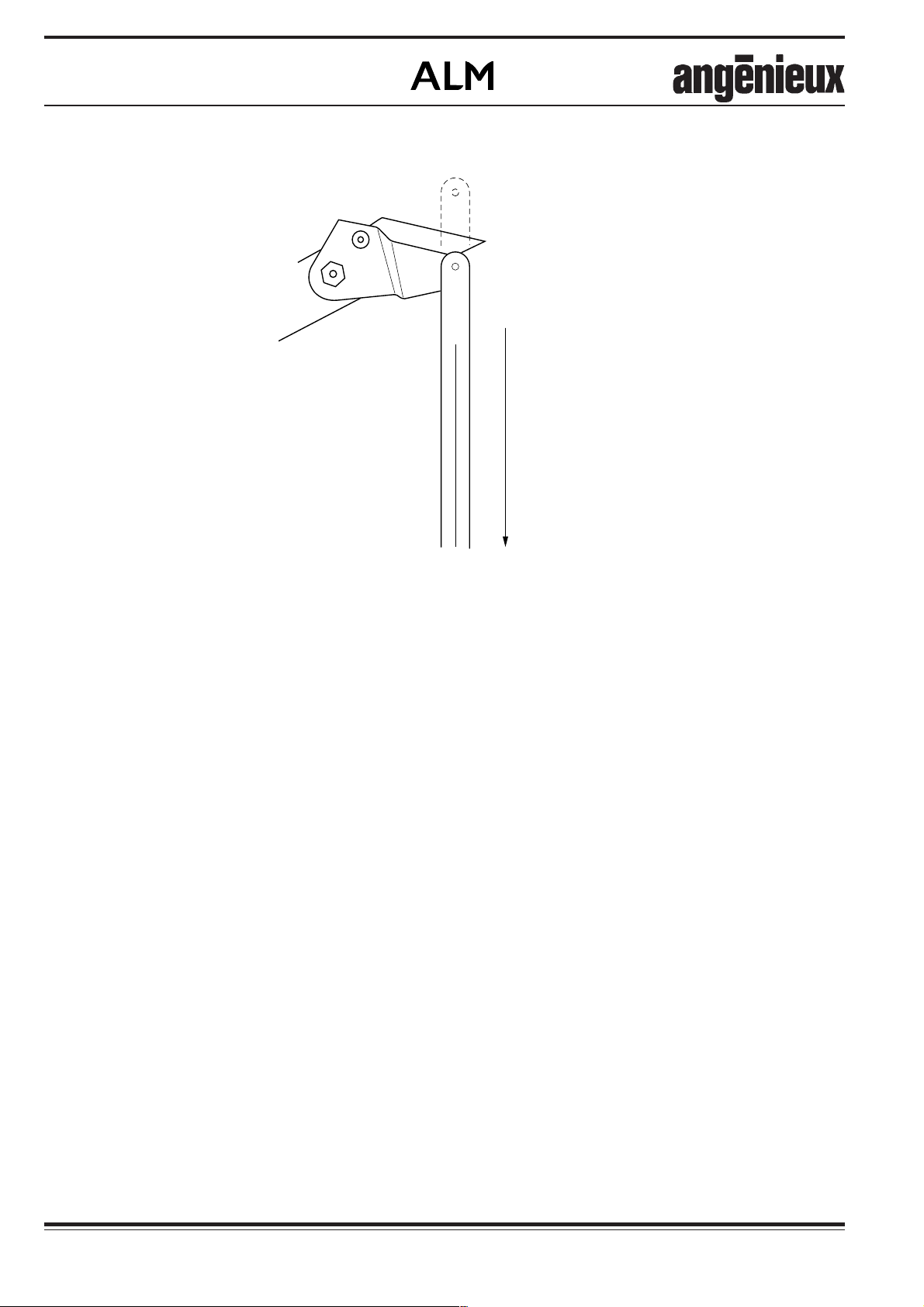
5) Régler les 4 miroirs mobiles :
a) retirer le cache d'un miroir
mobile.
b) tourner la poignée de focalisation
et amener la biellette servant à
l'articulation du miroir en limite de
course côté centre du projecteur
(FIG. 5).
c) ne pas toucher la poignée pendant toute la suite du réglage.
d) procéder ensuite de façon identique au réglage des miroirs fixes et
répéter l'opération pour les 4 miroirs mobiles.
Enlever les caches des 4 miroirs
mobiles et vérifier qu'ils se déplacent de façon simultanée et régulière.
6) Retirer tous les caches.
Focaliser au centre et affiner le
centrage si nécessaire ; la plage
d'éclairement doit être homogène
et régulière.
5) Adjust the 4 mobile mirrors:
a) remove the mask from the first
moving mirror window.
b) turn the focusing handle and
bring the connecting-rod used for
mirror articulation (see drawing) in
limit of motion when moving toward
the center of the lighthead (FIG. 5).
c) do not touch the handle util full
completion of the adjustment.
d) then proceed in the same way
with the adjustment of the fixed
mirrors and repeat the operation for
the 4 moving mirrors.
Remove the masks from the 4
moving mirrors windows and check
they are moving simultaneously and
regularly.
6) Remove all the masks.
Focus on the center and reajust the
lentering il necessary; the
illuminated area must be
homogeneous and regular.
5) Einstellung der 4 mobilen Spiegel:
a) Die Abdeckung eines mobilen
Spiegels entfernen.
b) Den Fokussierungsknopf drehen
um die zur Bewegung des Spiegels
dienende Stange zur Endlage, auf
der Mitte der Operationsleuchte, zu
bringen (Abb. 5).
c) Den Schalter nicht mehr berühren
solange die Einstellung nicht fertig
ist.
d) Auf dieselbe Art und Weise die
festliegenden Spiegel einstellen dann
denselben Arbeitschritt für die 4
mobilen Spiegel durchführen.
Die Abdeckungen der 4 mobilen
Spiegeln entfernen und sich
vergewissern, dass sie sich
gleichmäbig sich zusammen
bewegen.
6) Die gesamten Abdeckungen
entfernen.
Auf die Mitte fokussieren und wenn
nötig, das Zentrieren verfeinern. Der
Beleuchtungsbereich soll homogen
und gleichmässig sein.
010733103-3
Notice technique / Technical manual / Technische Anleitung
010733103
21
Éclairage opératoire
5
6
7
D
Surgical lighting system
OP-Leuchten
1
2
3
4
Tournevis
Tournevis
Screw driver
Screwdriver
estornillador
Schraubenzieher
010733003-20a
FIG. 1
010733103-3
22
010733103 Notice technique / Technical manual / Technische Anleitung

Éclairage opératoire
Surgical lighting system
OP-Leuchten
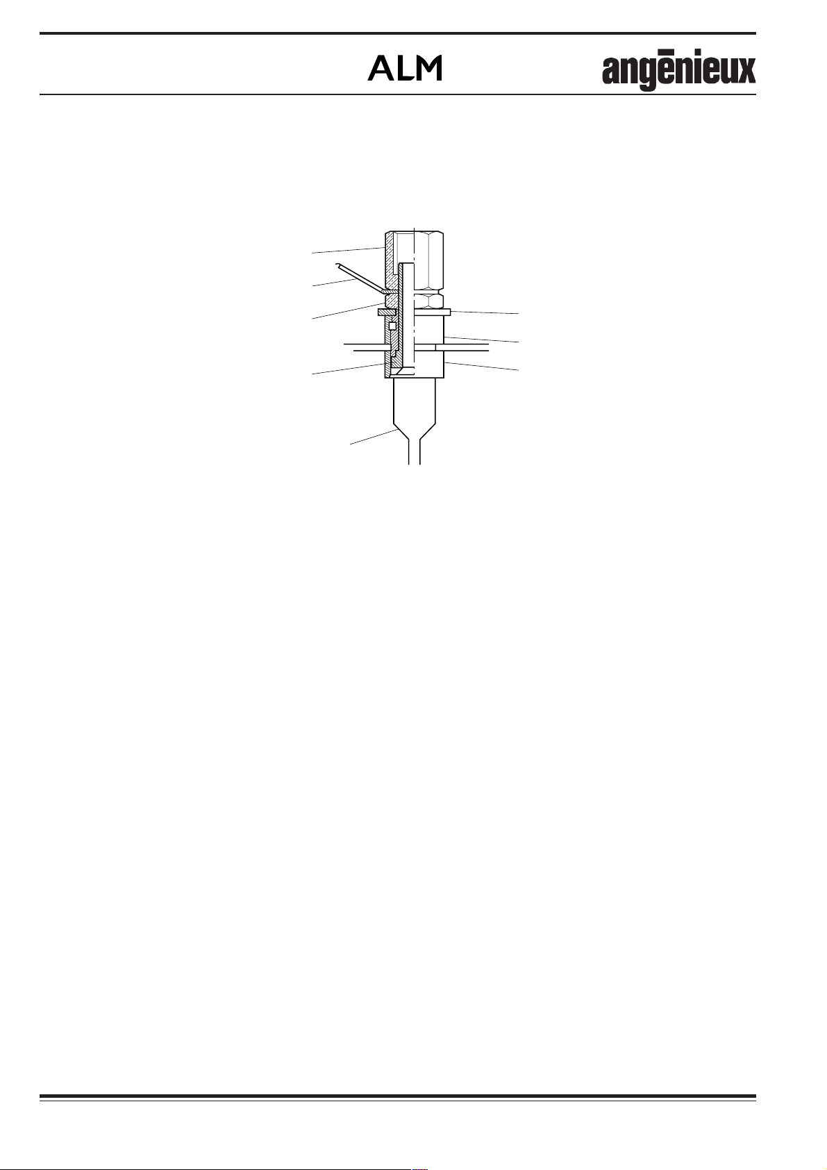
9 - CHANGEMENT DES
DOUILLES SUR LE BLOC
OPTIQUE
Numéro du sous-ensemble douille :
174723.
1) Retirer le bloc optique.
ATTENTION : Repérer le sens du
montage.
2) Se reporter au schéma (FIG. 1) pour
le changement des douilles.
a) Dévisser l'écrou (1) à l'aide de
deux clés plates de 8 mm. Retirer
l'écrou et la languette (2).
b) Engager un tournevis à lame
(largeur » 7mm) dans le bloc optique par l'orifice situé à l'opposé de
la douille à changer. Débloquer
l'écrou (3).
c) Oter l'écrou (3), la rondelle (5),
les douilles isolantes (6) et (7) ainsi
que la partie inférieure de la douille.
9 - REPLACEMENT OF THE
PLUGS ON THE OPTICAL
BLOC
Reference number of the plugs assy:
174723.
1) Remove the optical block.
CAREFUL: Check original positioning.
2) For the replacement of the plugs,
refer to the diagram (FIG. 1).
a) Unscrew the nut (1) thanks two
8 mm flat wrenches. Remove the
nut and the contact tab (2).
b) Introduce a screw driver through
a hole located in the inferior shell of
the optical block, in order to reach
the nut (3) and to unscrew it.
c) Remove the nut (3), the washer
(5), the insulating sockets (6) and
(7) and the inside shaft of the plug.
9 - AUSWECHSELN DER
BUCHSEN AUF DEM
OPTISCHEN BLOCK
Bezugs-Nr. Der Buchsen-Baugruppe :
174723.
1) Den optischen Block entfernen.
ACHTUNG: Die Montageweise
merken.
2) Zum Auswechseln der Buchsen,
siehe Zeichnung (Abb. 1).
a) Die Mutter (1) mit zwei 8-mmSchlüsseln lösen. Die Mutter und
Lasche (2) herausnehmen.
b) Den Schraubendreher mit Klinge
(Breite » 7 mm) durch das Loch, das
gegenüber der auszuwechselnde
Buchse liegt, in den optischen Block
führen. Die Mutter (3) lösen.
c) Die Mutter (3), Unterlegscheibe
(5), Isolierbuchsen (6) und (7) und
das Unterteil der Buchse
herausnehmen.
d) Engager une nouvelle douille isolante (7) et une nouvelle douille (4)
entre les lentilles du bloc optique.
Pour la mise en place de ces deux
pièces dans le flasque supérieur, il
est possible de s'aider d'une fine
tige.
e) Ensuite remonter les pièces
supérieures.
3) Remettre le bloc optique en place.
d) Place a new insulating socket
(7), then a new shaft (4) into the
superior shell of the optical block,
routing them upwards through the
lenses by means of a rod.
e) Then put back upper pieces.
3) Put in place the optical block.
d) Eine neue Isolierbuchse (7) und
eine neue Buchse (4) zwischen die
Linsen des optischen Blocks
einsetzen. Ein feiner Stab ermöglicht
es sie besser hereinzusetzen.
e) Die oberen Teile erneut montieren.
3) Den optischen Block erneut
einsetzen.
010733103-3
Notice technique / Technical manual / Technische Anleitung
010733103
23

Éclairage opératoire
Surgical lighting system
OP-Leuchten
24
010733103-3
010733103 Notice technique / Technical manual / Technische Anleitung

Éclairage opératoire
Surgical lighting system
OP-Leuchten
10 - NOMENCLATURES
ET PLANCHES
10 - PARTS LISTS AND
DRAWINGS
10 - STÜCKLISTE UND
ZEICHNUNGEN
010733103-3
Notice technique / Technical manual / Technische Anleitung
010733103
25

Éclairage opératoire
Surgical lighting system
OP-Leuchten
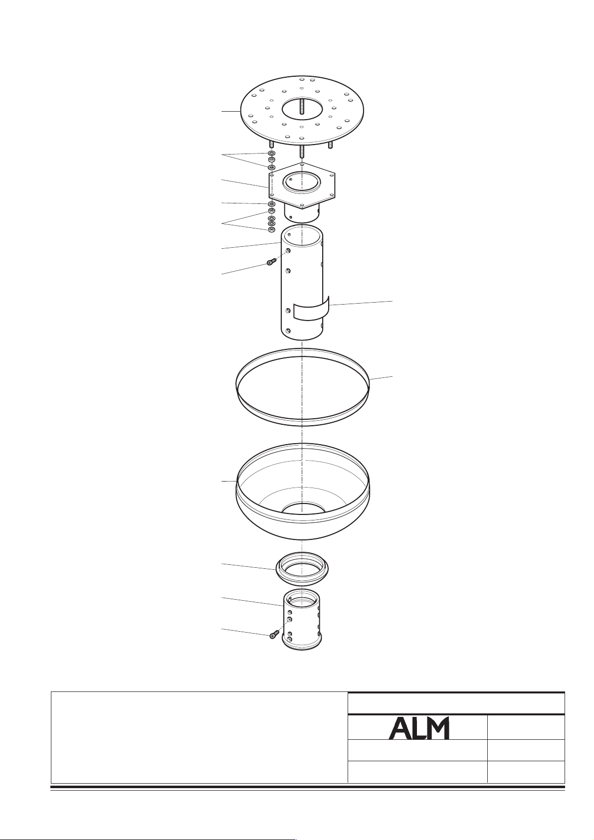
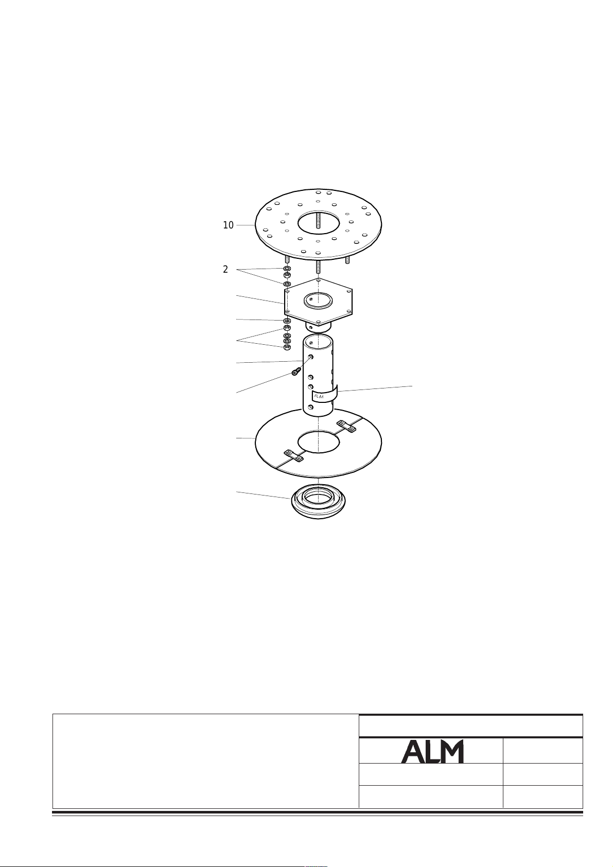
NOMENCLATURE 1 PLANCHE 1 BRIDE RENFORÇÉE
PARTS LIST 1 DRAWING 1 REINFORCED FLANGE
STÜCKLISTE 1 ZEICHNUNG 1 VERSTÄRKTE FLANSCH
PL. S/E REP. REFERENCE Qté
DR. S/A REF. REFERENCE DESIGNATION DESCRIPTION BESCHREIBUNG Qty
DA UBG ORTZ KENNZEICHEN Mg
1A 568051999 Bride renforçée Reinforced flange Verstärkter Flansch
10A 568009028 Platine plafonnière Ceiling plate Deckenarm-Platte 1
50A 568009013 Bride Flange Flansch 1
y
y
60A 568009043 Tube de suspension Suspension tube Aufhängungsröhre 1
à/to/bis
568009054
90A 568009018 Joint de tube f 149 mm Tube seal f 149 mm Röhrendichtung f 149 mm 1
y
100A 568009014 Fourreau Sleeve Hülse 1
y
y
130A 568009016 Joint capot plafonnier Ceiling cover seal Dichtung der Deckenarm-
abdeckung 1
26
010733003-3
010733003 Notice technique / Technical manual / Technische Anleitung
23
22
21
20
19
18
17
16
15
14
13
12
11
10
20
50
40
30
60
70
A
L
M
130
120
10
9
8
7
6
5
4
3
2
1
80
90
100
110
I HGF E DCB A
011333002-59
BRIDE RENFORÇÉE
REINFORCED FLANGE
VERSTÄRKTER FLANSCH
010733003-3
Notice technique / Technical manual / Technische Anleitung
PLANCHE/DRAWING/ZEICHNUNG
Modif :
Änd :
010733003
1
02/00
Garreau
27

Éclairage opératoire
Surgical lighting system
OP-Leuchten
NOMENCLATURE 2 PLANCHE 2 BRIDE SIMPLE
PARTS LIST 2 DRAWING 2 PLAIN FLANGE
STÜCKLISTE 2 ZEICHNUNG 2 EINFACHER FLANSCH
PL. S/E REP. REFERENCE Qté
DR. S/A REF. REFERENCE DESIGNATION DESCRIPTION BESCHREIBUNG Qty
DA UBG ORTZ KENNZEICHEN Mg
1A 568051999 Bride simple Plain flange Einfacher Flansch
10A 568009028 Platine plafonnière Ceiling plate Deckenarm-Platte 1
y
50A 568009011 Bride Flange Flansch 1
y
60A 568009035 Tube de suspension Suspension tube Aufhängungsröhre 1
à / to / bis
568009042
y
90A 568009017 Joint de tube f 105 mm Tube seal f 105 mm Röhrendichtung f 105
28
010733003-3
010733003 Notice technique / Technical manual / Technische Anleitung
23
22
21
20
19
18
17
16
10
15
14
13
12
11
10
9
8
7
6
20
50
40
30
60
70
80
90
$
/
0
1
0
T
A
L
P
120
5
4
3
2
1
I HGF E DCB A
BRIDE SIMPLE
PLAIN FLANGE
EINFACHER FLANSCH
010733003-3
Notice technique / Technical manual / Technische Anleitung
PLANCHE/DRAWING/ZEICHNUNG
Modif :
Änd :
010733003
2
02/00
Garreau
29
Éclairage opératoire
Surgical lighting system
OP-Leuchten
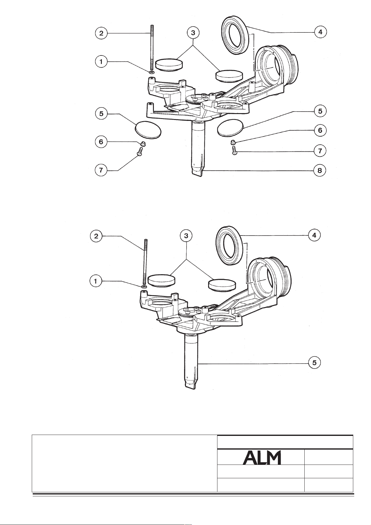
SUPPORT DE BLOC OPTIQUE
OPTICAL ASSEMBLY SUPPORT
HALTERUNG DES OPTISCHEN BLOCKS
NOMENCLATURE 3 PLANCHE 3 NOUVEAU MODÈLE SANS FILTRES CATATHERMIQUES CENTRAUX
PARTS LIST 3 DRAWING 3 NEW MODEL WITH CENTRAL ATHERMAL FILTERS
STÜCKLISTE 3 ZEICHNUNG 3 NEUES MODELL OHNE KATATHERMISCHEN FILTERN
PL. S/E REP. REFERENCE Qté
DR. S/A REF. REFERENCE DESIGNATION DESCRIPTION BEZEICHNUNG Qty
DA UBG ORTZ KENNZEICHEN Mg
1 950118 Ecrou M4 Nut M4 Mutter M4 4
2 151686 Tige fixation condenseur Optical condenser Besfestigungsstange des
attachment stud Kondensors 6
3 137724 Lentille centrale Central lens Zentrallinse 2
4 251302 Roulement billes Ball bearing Kugellager 1
5 153235 Hublot central pour AX 10 Central glass port for AX 10 Mittlere Luke für AX10 2
204897 Hublot central pour AX 14 Central glass port for AX 14 Mittlere Luke für AX14 2
6 204548 Entretoise Spacer Abstandsstück 6
7 185875 Vis Screw Schraube 6
y
8 125335 Ensemble de focalisation Focusing assembly Baugruppe der Fokussierung 1
NOMENCLATURE 3 PLANCHE 3 ANCIEN MODÈLE SANS FILTRES CATATHERMIQUES CENTRAUX
PARTS LIST 3 DRAWING 3 OLD MODEL WITHOUT CENTRAL ATHERMAL FILTERS
STÜCKLISTE 3 ZEICHNUNG 3 VORMALS MODELL OHNE ZENTRALEN
KATATHERMISCHEN FILTERN
PL. S/E REP. REFERENCE Qté
DR. S/A REF. REFERENCE DESIGNATION DESCRIPTION BEZEICHNUNG Qty
DA UBG ORTZ. KENNZEICHEN Mg
1 950118 Ecrou M4 Nut M4 Mutter M4 1
2 151686 Tige fixation condenseur Optical assy. fixation stud Befestigungsstange des
3 137724 Lentille centrale Central lens Zentrallinse 2
4 251302 Roulement billes Ball bearing Kugellager 1
5 125335 Ensemble de focalisation Focusing assembly Baugruppe der Fokussierung 1
30
010733103 Notice technique / Technical manual / Technische Anleitung
Kondensators 6
010733103-3
23
22
21
20
19
18
17
16
15
14
13
12
NOUVEAU MODÈLE SANS FILTRES CATATHERMIQUES CENTRAUX
NEW MODEL WITH CENTRAL ATHERMAL FILTERS
NEUES MODELL OHNE KATATHERMISCHE FILTER
11
10
9
8
7
6
5
4
3
2
1
ANCIEN MODÈLE SANS FILTRES CATATHERMIQUES CENTRAUX
OLD MODEL WITHOUT CENTRAL ATHERMAL FILTERS
VORMALS MODELL OHNE ZENTRALE KATATHERMISCHE FILTER
IHGFEDCBA
SUPPORT BLOC OPTIQUE
OPTICAL ASSEMBLY SUPPORT
HALTERUNG DES OPTISCHEN BLOCKS
010733003-3
Notice technique / Technical manual / Technische Anleitung
PLANCHE/DRAWING/ZEICHNUNG
Modif :
Änd :
010733003
3
02/00
Garreau
31

Éclairage opératoire
Surgical lighting system
OP-Leuchten
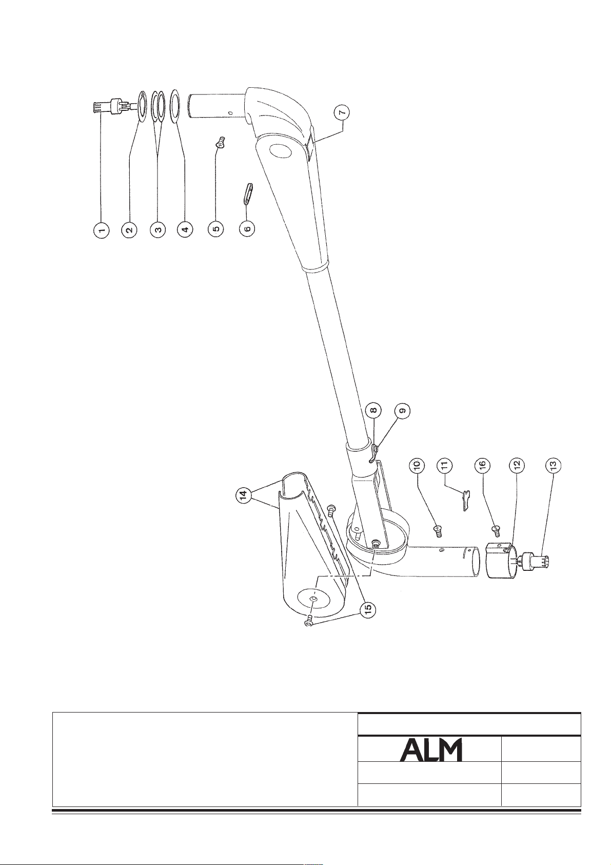
NOMENCLATURE 4 PLANCHE 4 S/E BRAS PRINCIPAL SIMPLE SAX
PARTS LIST 4 DRAWING 4 S/A SINGLE MAIN ARM SAX
STÜCKLISTE 4 ZEICHNUNG 4 UNTERBAUGRUPPE DES EINFACHEN HAUPTARMS SAX
PL. S/E REP. REFERENCE Qté
DR. S/A REF. REFERENCE DESIGNATION DESCRIPTION BESCHREIBUNG Qty
DA UBG ORTZ KENNZEICHEN Mg
1 204820 Vis de fixation du contact Male contact fixation screw Befestigungsschraube
mâle des Kontaktstifts 2
2 204815 Support de contact mâle Male contact support Auflage des Kontaktstifts 1
3 180362 Broche mâle Male contact Steckerstift 1
4 204823 Faisceau bras Arm cable harness Kabelbündel des Arms 1
5 204855 Frein du bras ressort Spring arm brake Bremse des Federarms 1
6 204862 Vis de fixation porte de Access plate fixation Befestigungsschraube
visite screw der Zugangsklappe 2
7 204858 Rondelle éventail Washer Fächerscheibe 1
8 204826 Porte de visite Brush assy access plate Zugangsklappe 1
9 204821 Porte balais Brush assembly Bürstenarm 1
10 204824 Vis de fixation cache de Protective cover fixation Befestigungsschraube der
protection Schutzabdeckung 3
11 204825 Cache de protection Protective cover Schutzabdeckung 1
12 189489 Frein d'axe central Central axis brake Bremse der Zentralachse 2
13 179111 Connecteur d'alimentation Supply connector Versorgungssteckverbinder 1
14 188396 Collier Collar Schelle 1
15 981328 Vis de fixation du cache Retaining screws Befestigungsschraube der
Abdeckung 3
16 274240 Cache Cover plate Abdeckung 1
32
010733003-3
010733003 Notice technique / Technical manual / Technische Anleitung

23
1
2
5
4
1
1
1
1
1
3
22
21
20
19
18
17
6
16
15
5
13
14
14
13
12
11
10
9
8
7
6
2
1
011333002-51
9
8
7
6
5
0
4
3
2
1
I HGF E DCB A
S/E BRAS PRINCIPAL SIMPLE SAX
S/A SINGLE MAIN ARM SAX
UNTERBAUGRUPPE DES EINFACHEN HAUPTARMS
SAX
010733003-3
PLANCHE/DRAWING/ZEICHNUNG
Modif :
Änd :
4
02/00
Garreau
Notice technique / Technical manual / Technische Anleitung
010733003
33

Éclairage opératoire
Surgical lighting system
OP-Leuchten
NOMENCLATURE 5 PLANCHE 5 S/E BRAS PRINCIPAL DOUBLE SAX
PARTS LIST 5 DRAWING 5 S/A DOUBLE MAIN ARM SAX
STÜCKLISTE 5 ZEICHNUNG 5 U/BG DES DOPPELTEN HAUPTARMS SAX
PL. S/E REP. REFERENCE Qté
DR. S/A REF. REFERENCE DESIGNATION DESCRIPTION BESCHREIBUNG Qty
DA UBG ORTZ KENNZEICHEN Mg
1 204820 Vis de fixation du contact Male contact fixation screw Befestigungsschraube
mâ le des Kontaktstifts 4
2 204815 Support de contact mâle Male contact support Auflage des Kontaktstifts 2
3 180362 Broche mâle Male contact Steckerstift 2
4 204823 Faisceau bras satellite Outer arm cable harness Kabelbündel des
Ausgleichsarm 1
5 204855 Frein du bras ressort Spring arm brake Bremse des Federarms 2
6 204822 Faisceau bras central Center arm cable harness Bremse des mittleren Arms 1
7 204862 Vis de fixation porte de Access plate fixation Befestigungsschraube
visite screw der Zugangsklappe
4
8 204858 Rondelle éventail Washer Fächerscheibe 2
9 204826 Porte de visite Brush assy access plate Zugangsklappe 2
10 204821 Porte balais Brush assembly Bürstenarm 2
11 204825 Cache de protection Protective cover Schutzabdeckung 1
12 204824 Vis de fixation cache de Protective cover fixation Befestigungsschraube
protection screw der Schutzabdeckung 3
13 189489 Frein d'axe central Central axis brake Bremse der Zentralachse 4
14 179111 Connecteur d'alimentation Supply connector Versorgungssteckverbinder 2
15 188396 Collier Collar Schelle 2
16 981328 Vis de fixation du cache Retaining screws Befestigungsschraube
der Abdeckung 3
17 274240 Cache Cover plate Abdeckung 1
18 187594 Rallonge 110mm Extender 110mm Verlängerungsrohr
von 110 mm 1
34
010733003-3
010733003 Notice technique / Technical manual / Technische Anleitung

23
8
1
1
1
1
1
1
1
22
21
20
19
18
17
16
15
14
13
12
11
10
9
7
6
1
2
5
14
4
4
5
1
011333002-53
6
3
8
3
7
10
9
8
7
6
5
4
3
2
1
1
2
I HGF E DCB A
S/E BRAS PRINCIPAL DOUBLE SAX
S/A DOUBLE MAIN ARM SAX
10
9
8
7
PLANCHE/DRAWING/ZEICHNUNG
02/00
Garreau
5
Modif :
U/BG DES DOPPELTEN HAUPTARMS SAX
010733003-3
Notice technique / Technical manual / Technische Anleitung
010733003
Änd :
35

Éclairage opératoire
Surgical lighting system
OP-Leuchten
NOMENCLATURE 6 PLANCHE 6 S/E BRAS PRINCIPAL TRIPLE SAX
PARTS LIST 6 DRAWING 6 S/A TRIPLE MAIN ARM SAX
STÜCKLISTE 6 ZEICHNUNG 6 U/BG DES DREIFACHEN HAUPTARMS SAX
PL. S/E REP. REFERENCE Qté
DR. S/A REF. REFERENCE DESIGNATION DESCRIPTION BESCHREIBUNG Qty
DA UBG ORTZ KENNZEICHEN Mg
1 204820 Vis de fixation du contact Male contact fixation screw Befestigungsschraube
mâle des Kontaktstifts 4
2 204815 Support de contact mâle Male contact support Auflage des Kontaktstifts 2
3 180362 Broche mâle Male contact Steckerstift 2
4 204823 Faisceau bras satellite Outer arm cable harness Kabelbündel des
Ausgleicharms 1
5 204855 Frein du bras ressort Spring arm brake Bremse des Federarms 2
6 204822 Faisceau bras central Center arm cable harness Kabelbündel des mittleren
Arms 1
7 204862 Vis de fixation porte de Access plate fixation screw Befestigungsschraube
visite der Zugangsklappe 4
8 204858 Rondelle éventail Washer Fächerscheibe 2
9 204826 Porte de visite Brush assy access plate Zugangsklappe 2
10 204821 Porte balais Brush assembly Bürstenarm 2
11 204825 Cache de protection Protective cover Schutzabdeckung 1
12 204824 Vis de fixation cache de Protective cover fixation Befestigungsschraube des
protection screw Schutzabdeckung 3
13 189489 Frein d'axe central Central axis brake Bremse der Zentralachse 4
14 179111 Connecteur d'alimentation Supply connector Versorgungssteckverbinder 2
15 188396 Collier Collar Schelle 2
16 981328 Vis de fixation du cache Retaining screws Befestigungsschraube
der Abdeckung 3
17 274240 Cache Cover plate Abdeckung 1
18 187594 Rallonge 110mm Extender 110mm Verlängerungsrohr
von 110 mm 1
19 187597 Rallonge 220mm Extender 220mm Verlängerungsrohr
von 220 mm 1
36
010733003-3
010733003 Notice technique / Technical manual / Technische Anleitung

23
9
1
1
1
1
22
21
20
19
18
17
7
6
16
15
14
14
5
14
1
2
4
13
4
12
5
11
10
9
8
7
13
6
5
011333002-55
1
6
5
18
3
4
11
3
12
2
1
I HGF E DCB A
S/E BRAS PRINCIPAL TRIPLE SAX
S/A TRIPLE MAIN ARM SAX
U/BG DES DREIFACHEN HAUPTARMS SAX
010733003-3
Notice technique / Technical manual / Technische Anleitung
10
9
8
7
PLANCHE/DRAWING/ZEICHNUNG
02/00
Garreau
6
Modif :
Änd :
010733003
37

Éclairage opératoire
Surgical lighting system
OP-Leuchten
NOMENCLATURE 7 PLANCHE 7 PROJECTEUR AX4
PARTS LIST 7 DRAWING 7 AX4 LIGHTHEAD
STÜCKLISTE 7 ZEICHNUNG 7 OPERATIONSLEUCHTE AX4
PL. S/E REP. REFERENCE Qté
DR. S/A REF. REFERENCE DESIGNATION DESCRIPTION BESCHREIBUNG Qty
DA UBG ORTZ KENNZEICHEN Mg
1 186193 Capot central Bulb cover (white) Zentrale Abdeckhaube 1
2 162798 Support de lampe -150 W Bulb holder - 150 W Lampenhalterung - 150 W 1
3 163508 Lampe 150W G6.35 Bulb 150W G6.35 Glühlampe 150 W G6.35 1
4 187465 Bloc optique Optical block Optischen Block 1
5 986118 Vis CHc M3 - 10 Screw CHc M3 -10 Schraube CHc M3 - 10 4
6 971078 Rondelle DE3 Washer DE3 Scheibe DE3 4
7/8 130782 Capot bras Arm cover Verkleidung des Arms 4
9 104857 Poignée Non sterile handle Griff 1
10 971045 Rondelle DE 4 Washer DE 4 Scheibe DE4 2
11 981418 Vis CBL M4 - 10 Screw CBL M4 - 10 Schraube CBL M4 - 10 2
12 153627 Vis de fixation capot Lighthead casing screw Befestigungsschraube der
Abdeckhaube 4
13 153513 Cache vis Screw cover Schraubenabdeckung 4
14 130779 Bras Arm Arm 2
15 130780 Bras porte palier Arm (side) Arm, Lagerträger 2
16 981418 Vis CBL M 4 - 10 Screw CBL M 4 - 10 Schraube CBL M4 - 10 20
17 180247 S/ensemble arceau équipé C - arm sub-assy. Unterbaugruppe des
bestückten Bügels 1
18 193128 S/ensemble pièces bout Yoke end sub-assy. Unterbaugruppe der Teile am
d'arceau Bügelende 2
19 104061 Frein Spring Sicherung 2
20 174723 Douille panneau Bulb holder socket assy. Buchse, Paneel 2
22 984678 Vis FHc M 4 - 16 Screw FHc M 4 - 16 Schraube FHc M4 - 16 4
23 950118 Ecrou H M4 Nut H M4 Mutter H M4 4
24 984948 Vis FHc M 5 - 14 Screw FHc M 5 -14 Schraube FHc M5 - 14 8
25 950228 Ecrou H M5 Nut H M5 Mutter H M5 8
26 180233 Faisceau de tête AX 4 Cable harness AX 4 Kopf-Kabelbündel AX 4 1
27 110519 Joint torique Arm seal Dichtungsring 4
28 187306 Poignée stérilisable Sterilisable handle Sterilisierbarer Griff 1
29 158989 Support inférieur Outer lower glass port retainer Untere Halterung 4
38
010733003 Notice technique / Technical manual / Technische Anleitung
010733003-3

23
22
21
20
19
18
17
16
15
14
13
12
11
10
9
8
7
6
5
4
3
2
1
I HGF E DCB A
PROJECTEUR AX4
AX4 LIGHTHEAD
OPERATIONSLEUCHTE AX4
010733003-3
Notice technique / Technical manual / Technische Anleitung
PLANCHE/DRAWING/ZEICHNUNG
Modif :
Änd :
010733003
7
02/00
Garreau
39

Éclairage opératoire
Surgical lighting system
OP-Leuchten
NOMENCLATURE 7 PLANCHE 7 PROJECTEUR AX4
PARTS LIST 7 DRAWING 7 A 4 LIGHTHEAD
STÜCKLISTE 7 ZEICHNUNG 7 OPERATIONSLEUCHTE AX4
PL. S/E REP. REFERENCE Qté
DR. S/A REF. REFERENCE DESIGNATION DESCRIPTION BESCHREIBUNG Qty
DA UBG ORTZ KENNZEICHEN Mg
30 205326 Hublot micro lentilles Outer glass port micro lenses Luke der Mikrolinsen 4
31 160175 Support supérieur Outer upper glass port retainer Obere Halterung 4
32 909130 Vis autotaraudeuse M 4 - 9 Screw M 4 - 9 Schneidschraube M4 - 9 2 4
33 135976 Sous-ensemble miroir collé Dichroic mirror Unterbaugruppe des
geklebten Spiegels 4
34 104188 Levier-bielle sertie Focus lever Hebel - Stange, gefalzt 4
35 77690 Axe support de miroir Mirror axis pin
36 77691 Ecrou Axis pin nut Mutter 8
37 921380 Anneau 7103 Spring clip 7103 Ring 7103 8
38 971068 Rondelle M 3 U Washer M 3 U Scheibe M3 U 4
39 986148 Vis CHc M 3 - 6 Screw CHc M 3 - 6 Schraube CHc M3 - 6 4
40 105209 Ensemble de focalisation Focusing assy. Baugruppe der Fokussierung 1
41 130781 Fût Centre housing Schaft 1
42 186468 Porte ressort équipé Spring holder assy. Federhalterung, bestückt 2
43 971048 Rondelle DE 4 Washer DE 4 Scheibe DE4 8
44 113460 Moyeu Axis Nabe 1
45 270602 Broche mâle Male plug Steckerstift 1
46 981448 Vis CL M 3 - 10 Screw CL M 3 - 10 Schraube CL M3 - 10 2
47 971068 Rondelle M 3 U Washer M 3 U Scheibe M 3 U 2
48 185404 Vis RL M5 - 16 Screw RL M5 -16 Schraube RL M5 - 16 2
49 971048 Rondelle dentée DE 4 Washer DE 4 Zahnscheibe DE 4 2
50 950118 Ecrou M4 Nut M4 Mutter M4 1
Halterungsachse des Spiegels 8
40
010733003-3
010733003 Notice technique / Technical manual / Technische Anleitung

23
22
21
20
19
18
17
16
15
14
13
12
11
10
9
8
7
6
5
4
3
2
1
I HGF E DCB A
PROJECTEUR AX4
AX4 LIGHTHEAD
OPERATIONSLEUCHTE AX4
010733003-3
Notice technique / Technical manual / Technische Anleitung
PLANCHE/DRAWING/ZEICHNUNG
Modif :
Änd :
010733003
7
02/00
Garreau
41

Éclairage opératoire
Surgical lighting system
OP-Leuchten
NOMENCLATURE 8 PLANCHE 8 BRAS D'ÉQUILIBRAGE AX14
PARTS LIST 8 DRAWING 8 BALANCE ARM AX14
STÜCKLISTE 8 ZEICHNUNG 8 AUSGLEICHARM AX14
PL. S/E REP. REFERENCE Qté
DR. S/A REF. REFERENCE DESIGNATION DESCRIPTION BESCHREIBUNG Qty
DA UBG ORTZ KENNZEICHEN Mg
1 180363 Fiche femelle Female plug Steckdose 1
2 204819 Circlips Retaining clip Sicherungsring 1
3 204816 Rondelle de friction Friction washer Spannscheibe
4 204817 Rondelle d'appui Spacer Unterlegscheibe 2
5 204861 Vis de fixation fiche femelle Female plug fixation screw Befestigungsschraube
der Steckdose 1
6 204850 Cache de réglage Maximum height Abdeckung der
débattement adjustment cover Schwenkeinstellung 1
7 204849 Languette de protection Dust plate Schutzlasche 1
8 204867 Verrou Safety bolt Riegel 1
9 204845 Vis de fixation du verrou Safety bolt fixation screw Befestigungsschraube des
Riegels 1
10 204864 Vis de fixation fiche femelle Female plug fixation screw Befestigungsschraube
der Steckdose 1
11 113567 Secteur Retaining clip Bogenstück 1
12 113568 Bague de verrouillage Retaining collar Verriegelungsring 1
13 180363 Fiche femelle Female plug Steckdose 1
14 274368 Demi cache Hemi cover Halb-Abdeckung 2
15 274369 Vis de fixation du cache Protective cover fixation Befestigungsschraube
screw der Abdeckung 2
16 204842 Vis d'arrêt bague de Retaining collar screw Anschlagschraube
verrouillage des Verriegelungsrings 1
42
010733003-3
010733003 Notice technique / Technical manual / Technische Anleitung
23
22
21
20
19
18
17
16
15
14
13
12
11
10
9
8
7
6
5
4
3
2
1
I HGF E DCB A
BRAS D'ÉQUILIBRAGE AX14
BALANCE ARM AX14
AUSGLEICHARM AX14
010733003-3
Notice technique / Technical manual / Technische Anleitung
PLANCHE/DRAWING/ZEICHNUNG
Modif :
Änd :
010733003
8
02/00
Garreau
43

Éclairage opératoire
Surgical lighting system
OP-Leuchten
NOMENCLATURE 9 PLANCHE 9 PROJECTEUR AX14
PARTS LIST 9 DRAWING 9 AX14 LIGHTEAD
STÜCKLISTE 9 ZEICHNUNG 9 OPERATIONSLEUCHTE AX14
PL. S/E REP. REFERENCE Qté
DR. S/A REF. REFERENCE DESIGNATION DESCRIPTION BESCHREIBUNG Qty
DA UBG ORTZ KENNZEICHEN Mg
1 125330 Capot central équipé Bulb cover Zentrale Abdeckhaube, 1
bestückt
2 153093 Joint capot Bulb cover seal Dichtung, Abdeckhaube 1
3 125329 Grand capot équipé Upper casing Grobe Abdeckung, bestückt 1
4 137704 Poignée Non sterile handle Griff 4
5 909107 Vis autotaraudeuse M4 - 8 Screw M4 - 8 Schneidschraube M4 - 8 8
6 154241 Joint capot Cover seal Dichtung, Abdeckhaube 1
7 153627 Vis fixation capot Lighthead casing screw Befestigungsschraube,
Abdeckhaube 8
8 153513 Cache vis Screw cover (silicone) Schraubenabdeckung 8
9 162798 Support lampe Bulb holder - 150W Lampenhalterung 2
10 163508 Lampe 150 W G6.35 Bulb 150 W G6.35 Glühlampe 150 W G6.35 2
11 187465 Bloc optique Optical block Optischer Block 2
12 204582 Hublot central Centre glass port Luke, mittlere 2
13 270590 Arrêtoir Athermal filter holder Sperre 16
14 156153 Hublot catathermique Athermal filter Luke, katathermisch 8
15 174723 Douille panneau Bulb holder socket assy. Buchse, Paneel
16 950118 Ecrou H M4 Nut H M4 Mutter H M4 8
17 971048 Rondelle DE 4 Washer DE 4 Scheibe DE4 4
18 139026 Entretoise Centering washer Abstandstück 4
19 204866 Vis de fixation fiche femelle Female plug fixation screw Befestigungsschraube,
Steckdose 1
20 204863 Vis de fixation bague de Retaining collar fixation screw Befestigungsschraube,
verrouillage Verriegelungsring 1
21 204833 Bague de verrouillage Retaining collar Verriegelungsring 1
22 205098 Faisceau Cable harness Kabelbündel 1
23 138495 Joint Seal Dichtung 1
24 204814 Frein d'arceau Yoke break Bügelbremse 1
25 Manchon Sleeve Muffe
26 125328 Base équipée Lower casing Sockel, bestückt 1
27 158989 Support inférieur Outer lower glass port retainer Halterung, untere 4
28 205326 Hublot extérieur micro Outer glass port micro lenses Luke , auben, Mikrolinsen 4
lentilles
29 160175 Support supérieur Outer upper glass port retainer Halterung, obere 4
30 158990 Support inférieur Inter. lower glass port retainer Halterung, untere 4
31 205325 Hublot intermédiaire micro Intermediate glass port micro Luke, zwischen Mikrolinsen 4
lentilles lenses
44
010733003 Notice technique / Technical manual / Technische Anleitung
010733003-3
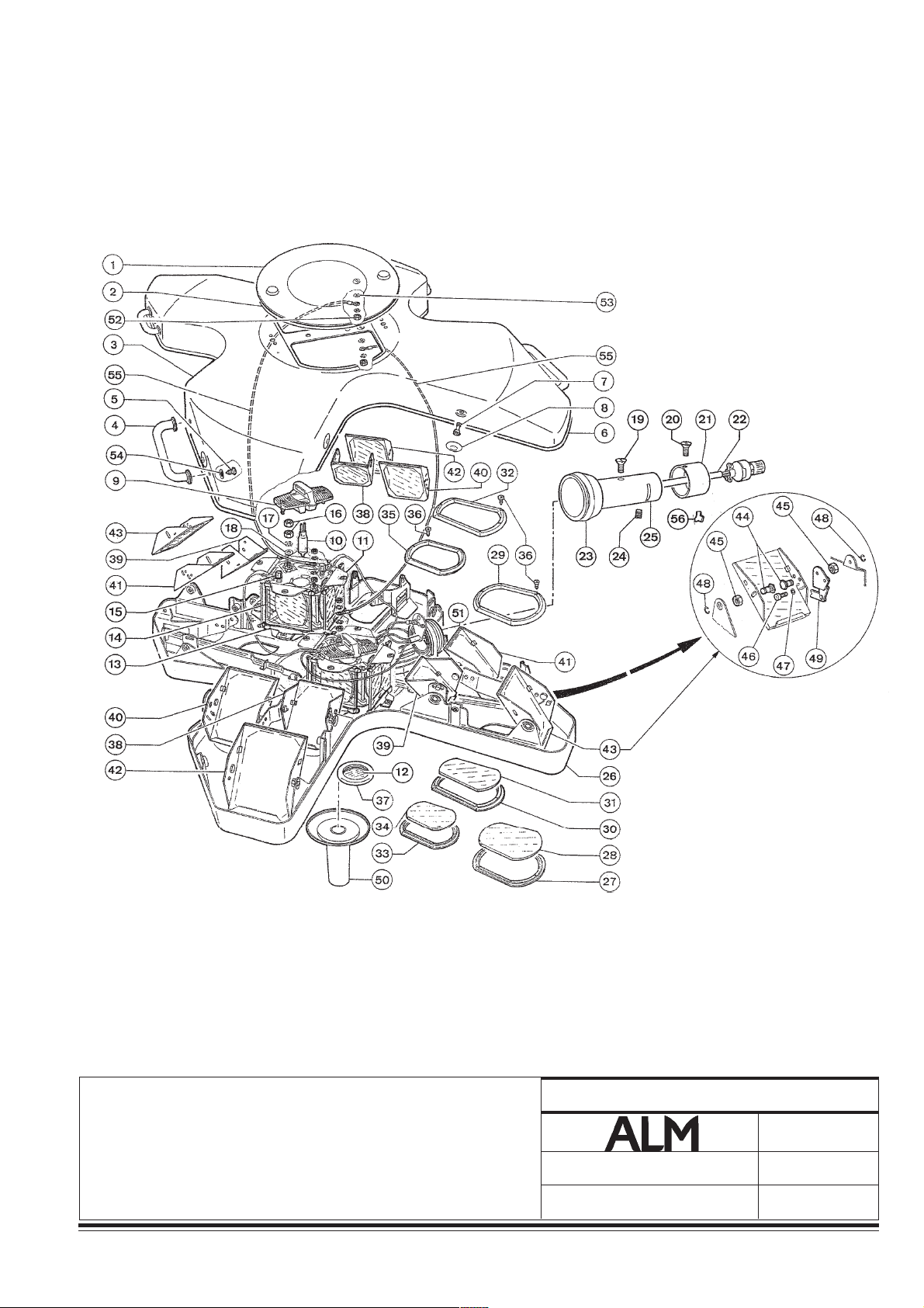
23
22
21
20
19
18
17
16
15
14
13
12
11
10
9
8
7
6
5
4
3
2
1
I HGF E DCB A
PROJECTEUR AX14
AX14 LIGHTHEAD
OPERATIONSLEUCHTE AX14
010733003-3
Notice technique / Technical manual / Technische Anleitung
PLANCHE/DRAWING/ZEICHNUNG
Modif :
Änd :
010733003
9
02/00
Garreau
45

Éclairage opératoire
Surgical lighting system
OP-Leuchten
NOMENCLATURE 9 PLANCHE 9 PROJECTEUR AX14
PARTS LIST 9 DRAWING 9 AX14 LIGHTEAD
STÜCKLISTE 9 ZEICHNUNG 9 OPERATIONSLEUCHTE AX14
PL. S/E REP. REFERENCE Qté
DR. S/A REF. REFERENCE DESIGNATION DESCRIPTION BESCHREIBUNG Qty
DA UBG ORTZ KENNZEICHEN Mg
32 160176 Support supérieur Inter. upper glass port retainer Halterung, obere 4
33 158991 Support inférieur Inner. lower glass port retainer Halterung, untere 4
34 205324 Hublot interne micro lentilles Inner glass port micro lenses Luke, innere, Mikrolinsen 4
35 160177 Support supérieur Inner upper glass port retainer Halterung, obere 4
36 909130 Vis autotaraudeuse M4 - 9 Screw M4 - 9 Schneidschraube M4 - 9 72
37 138958 Barillet central Centre glass port seal Federgehäuse, zentrales 2
38 125342 Support miroir SR droit Dichroic mirror Spiegelhalterung,
(right semi-coated) halb abgedeckt, rechts 2
39 125343 Support miroir SR gauche Dichroic mirror (left semi-coated) Spiegelhalterung,
halb abgedeckt, links 2
40 125346 Support miroir froid fixe gauche Dichroic mirror (left fixed) Spiegelhalterung, kalt,
festliegend, links 2
41 125347 Support miroir froid fixe droit Dichroic mirror (right fixed) Spiegelhalterung, kalt,
festliegend, rechts 2
42 125344 Support miroir froid mobile Dichroic mirror (left mobile) Spiegelhalterung, kalt, mobil
43 125345 Support miroir froid mobile Dichroic mirror (right mobile) Spiegelhalterung, kalt, mobil
44 77690 Axe support miroir Mirror axis pin Achse der Spiegelhalterung 2 0
153411 Axe support miroirs fixes Fixed mirror axis pin Achse der Spiegelhalterung,
45 77691 Ecrou axes miroirs Axis pin nut Mutter der Spielgelachsen 2 4
46 986148 Vis CHc M3 - 6 Screw CHc M3 - 6 Schraube CHc M3 - 6 12
47 971068 Rondelle M3 U Washer M3 U Scheibe M 3 U 12
48 921380 Anneau 7103 Spring clip 7103 Ring 7103 24
49 138449 Levier M.F mobile gauche Focus lever (left) Fokussierungshebel, mobil,
138448 Levier M.F mobile droit équipé Focus lever (right) Fokussierungshebel, mobil,
50 187306 Poignée stérilisable Sterilisable handle Griff, sterilisierbar 1
gauche links 2
droit rechts 2
festliegend 4
équipé links, bestückt 2
rechts, bestückt 2
51 Support de bras d'articulation Optical assembly support Halterung des Schwenkarms 1
voir 188377 - A See 188377 - A Siehe 188377 - A
52 950118 Ecrou M4 Nut M4 Mutter M4 6
53 971048 Rondelle dentée DE 4 Washer DE 4 Zahnscheibe DE 4 8
54 971045 Rondelle Washer Scheibe 8
55 188062 Cordon de masse Earthing wire Masse-Verbindungsleitung 2
56 113567 Secteur Retaining clip Bogenstück
46
010733003 Notice technique / Technical manual / Technische Anleitung
010733003-3
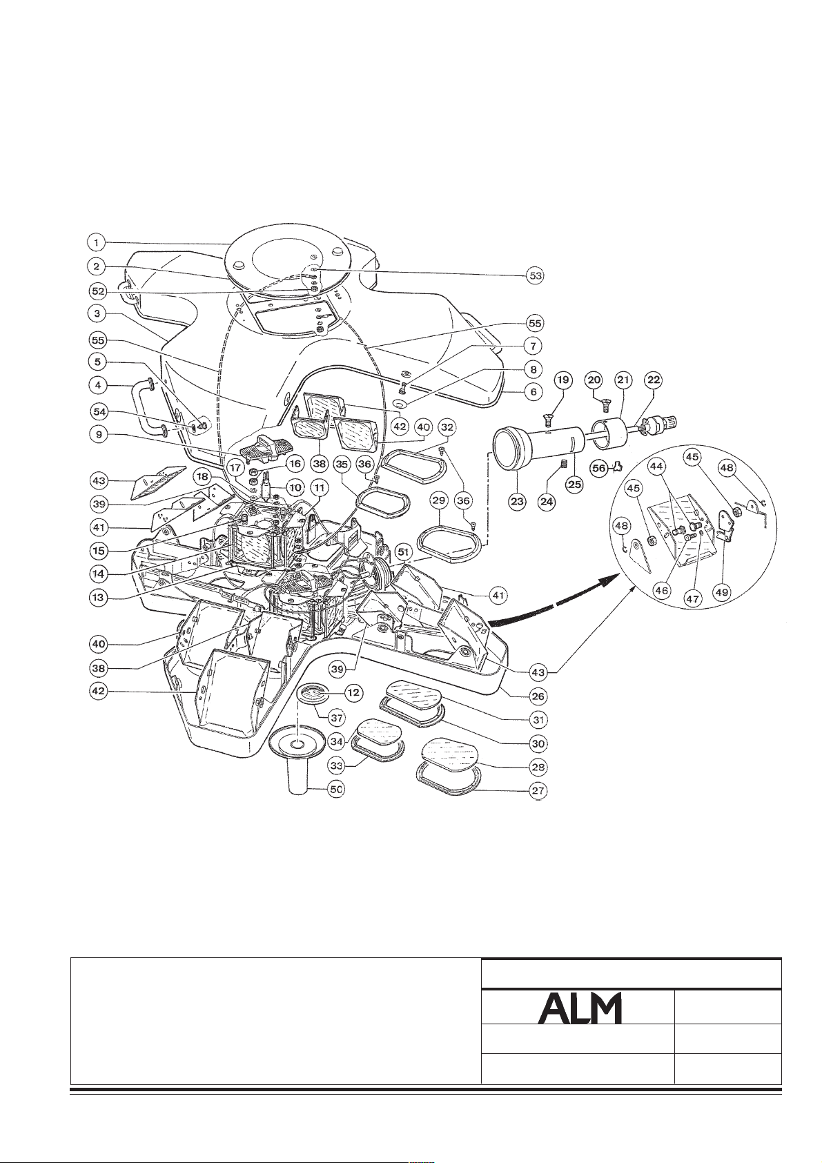
23
22
21
20
19
18
17
16
15
14
13
12
11
10
9
8
7
6
5
4
3
2
1
I HGF E DCB A
PROJECTEUR AX14
AX14 LIGHTHEAD
OPERATIONSLEUCHTE AX14
010733003-3
Notice technique / Technical manual / Technische Anleitung
PLANCHE/DRAWING/ZEICHNUNG
Modif :
Änd :
010733003
9
02/00
Garreau
47

Éclairage opératoire
Surgical lighting system
OP-Leuchten
NOMENCLATURE 10 PLANCHE 10 BRAS D'ÉQUILIBRAGE AX4
PARTS LIST 10 DRAWING 10 SPRING ARM AX4
STÜCKLISTE 10 ZEICHNUNG 10 AUSGLEICHARM AX4
PL. S/E REP. REFERENCE Qté
DR. S/A REF. REFERENCE DESIGNATION DESCRIPTION BESCHREIBUNG Qty
DA UBG ORTZ KENNZEICHEN Mg
1 180363 Fiche femelle Female plug Steckdose 1
2 204819 Circlips Retaining clip Sicherungsring 1
3 204816 Rondelle de friction Friction washer Spannscheibe 2
4 204817 Rondelle d'appui Spacer Unterlegscheibe 1
5 204861 Vis de fixation fiche femelle Female plug fixation screw Befestigungsschraube der
Steckdose 1
6 204850 Cache de réglage Maximum height adjustment Abdeckung der
débattement cover Schwenkeinstellung 1
7 204849 Languette de protection Dust plate Schutzlasche 1
8 204867 Verrou Safety bolt Riegel 1
9 204845 Vis de fixation du verrou Safety bolt fixation screw Befestigungsschraube des
Riegels 1
10 204864 Vis de fixation fiche femelle Female plug fixation screw Befestigungsschraube,
Steckdose 1
11 113567 Secteur Retaining clip Bogenstück 1
12 113568 Bague de verrouillage Retaining collar Verriegelungsring 1
13 180363 Fiche femelle Female plug Steckdose 1
14 179426 Cache plastique Protective cover Abdeckung aus Plastik 1
15 981448 Vis de fixation du cache Protective cover fixation screw Befestigungsschraube der
Abdeckung 1
16 204842 Vis d'arrêt bague de Retaining collar screw Anschlagschraube des
verrouillage Verriegelungsrings 1
48
010733003-3
010733003 Notice technique / Technical manual / Technische Anleitung

23
22
21
20
19
18
17
16
15
14
13
12
11
10
9
8
7
6
5
4
3
2
1
I HGF E DCB A
BRAS D'ÉQUILIBRAGE AX4
SPRING ARM AX4
AUSGLEICHARM AX4
010733003-3
Notice technique / Technical manual / Technische Anleitung
PLANCHE/DRAWING/ZEICHNUNG
Modif :
Änd :
010733003
10
02/00
Garreau
49

Éclairage opératoire
Surgical lighting system
OP-Leuchten
NOMENCLATURE 11 PLANCHE 11 BRAS D'ÉQUILIBRAGE, COUPOLE 4000-AX10 S/SAX
PARTS LIST 11 DRAWING 11 BALANCING ARM,AX10-4000 CUPOLA ON S/SAX
STÜCKLISTE 11 ZEICHNUNG 11 AUSGLEICHARM S/SAX DER 4000-AX10-SCHALE
PL. S/E REP. REFERENCE Qté
DR. S/A REF. REFERENCE DESIGNATION DESCRIPTION BESCHREIBUNG Qty
DA UBG ORTZ KENNZEICHEN Mg
1A 567209995 Bras d'équilibrage DF 4000 4000/AX10 SA/SAX/ACS Ausgleicharm DF 4000
AX10 série SA/SAX/ACS DF balancing arm AX10 Baureihe SA/SAX/ACS
1B 567211995 Bras d'équilibrage Video 4000 DF Ausgleicharm,
DF 4000 Vidéo balancing arm DF 4000 video
1C 567218995 Bras d'équilibrage SF 4000 4000/AX10 SA/SAX/ACS Ausgleicharm SF 4000
AX10 série SA/SAX/ACS SF balancing arm AX10 Baureihe SA/SAX/ACS
1D 567212995 Bras d'équilibrage Video 4000 SF Ausgleicharm
SF 4000 Vidéo balancing arm SF 4000 video
35A 567008002 Frein Brake Bremse 1
125A 367202555 Jeu de réparation Repair kit Reparatursatz
(cache + segment) (Cover + segment) (Abdeckung + Bogenstück) 1
Comprenant (rep.130A, comprising (items 130A, beinhaltet (ref. 130A,
140A, 150A, et 70A) 140A, 150A and 70A) 140A, 150A y 70A)
50
010733003-3
010733003 Notice technique / Technical manual / Technische Anleitung

23
22
21
20
10
20
30
31
32
33
32
19
18
17
16
15
14
13
12
11
10
9
BRAS D'EQUILIBRAGE DF
DF BALANCING ARM
AUSGLEICHARM DF
95
125
85
120
130
140
150
95
100
110
35
34
40
50
60
70
S
C
A
0
0
0
4
E
B
E
V
8
7
6
BRAS D'EQUILIBRAGE SF
SF BALANCING ARM
160
10
AUSGLEICHARM SF
5
4
3
2
1
I HGF E DCB A
130
170
BRAS D'ÉQUILIBRAGE 4000-AX10 S/SAX
AX10-4000 CUPOLA BALANCING ARM ON S/SAX
AUSGLEICHARM S/SAX DER 4000-AX10 -SCHALE
010733003-3
180
210
220
200
190
PLANCHE/DRAWING/ZEICHNUNG
Modif :
Änd :
11
02/00
Garreau
Notice technique / Technical manual / Technische Anleitung
010733003
51

Éclairage opératoire
Surgical lighting system
OP-Leuchten
NOMENCLATURE 12 PLANCHE 12 PROJECTEUR AX10
PARTS LIST 12 DRAWING 12 AX10 LIGHTEAD
STÜCKLISTE 12 ZEICHNUNG 12 OPERATIONSLEUCHTE AX10
PL. S/E REP. REFERENCE Qté
DR. S/A REF. REFERENCE DESIGNATION DESCRIPTION BESCHREIBUNG Qty
DA UBG ORTZ KENNZEICHEN Mg
1 125330 Petit capot équipé Little cover assy. Abdeckung, kleiner, bestückt 1
2 154544 Bouton 1/4 tour Bulb cover knob Drucktaster ¼ Umdrehung 2
3 153093 Joint capot central Bulb cover seal Dichtung, zentrale
Abdeckhaube 1
4 186752 Grand capot équipé Tall cover assy. Abdeckung, grob, bestückt 1
5 104857 Poignée Non sterile handle Griff 4
6 971045 Rondelle dentée DE 4 Washer DE 4 Zahnscheibe DE 4 8
7 981418 Vis CBL M4 Screw CBL M4 Schraube CBL M4 8
8 187482 Tôle sertie Upper casing wing retainer Blech, gefalzt 4
9 186984 Entretoise Spacer column Abstandstück 4
10 152318 Support de miroir Dichroic mirror holder Spiegelhalterung 8
11 135975 Miroir froid Dichroic mirror Spiegel, kalt 8
12 162798 Support de lampe Bulb holder Lampenhalterung 2
13 186762 Lampe G6.35 100/24 Bulb G6.35 100/24 Glühlampe G6.35 100/24 2
14 950118 Ecrou H M4 Nut H M4 Mutter H M4 32
15 971048 Rondelle DE 4 Washer DE 4 Scheibe DE 4 20
y
16 187465 Bloc optique Optical block Optischen Block 2
y
17 156153 Hublot catathermique Athermal filters Luke, katathermische 2
18 160176 Support supérieur Upper glass port retainer Halterung, obere 8
19 151686 Tige Rod Stange 6
20 Support de bras articulé Yoke assembly support Halterung des
188 377- A 188 377- A Schwenkarms 188 377-A 1
21 187909 Pièce fixation capot Upper casing fixation nut Befestigungsteil, Abdeckung 4
22 204576 Vis retouchée Screw Tornillo rectificado 4
23 187394 Rondelle nylon Nylon washer Scheibe aus Nylon 4
y
24 205325 Hublot micro lentilles Glass port micro lenses Luke, Mikrolinsen 8
25 158990 Support inférieur Inner lower glass port retainer Halterung, untere 8
26 204582 Hublot central Centre glass port Luke, zentrale 2
27 138958 Barillet central Centre glass port seal Federgehäuse, zentrales 2
28 187306 Poignée stérilisable Sterilisable handle Sterilisierbarer Griff 1
29 113567 Secteur Retaining clip Bogenstück 1
y
30 204866 Vis de fixation fiche femelle Female plug fixation screw Befestigungsschraube,
Steckdose 1
52
010733003 Notice technique / Technical manual / Technische Anleitung
010733003-3

23
22
21
20
19
18
17
16
15
14
13
12
11
10
9
8
7
6
5
4
3
2
1
I HGF E DCB A
PROJECTEUR AX10
AX10 LIGHTHEAD
OPERATIONSLEUCHTE AX10
010733003-3
Notice technique / Technical manual / Technische Anleitung
PLANCHE/DRAWING/ZEICHNUNG
Modif :
Änd :
010733003
12
02/00
Garreau
53

Éclairage opératoire
Surgical lighting system
OP-Leuchten
NOMENCLATURE 12 PLANCHE 12 PROJECTEUR AX10
PARTS LIST 12 DRAWING 12 AX10 LIGHTEAD
STÜCKLISTE 12 ZEICHNUNG 12 OPERATIONSLEUCHTE AX10
PL. S/E REP. REFERENCE Qté
DR. S/A REF. REFERENCE DESIGNATION DESCRIPTION BESCHREIBUNG Qty
DA UBG ORTZ KENNZEICHEN Mg
y
31 Manchon Sleeve Muffe 1
32 138495 Joint Seal Dichtung 1
33 204814 Frein d'arceau Yoke Break Bügelbremse 1
34 205098 Faisceau Cable harness Kabelbündel 1
35 204863 Vis de fixation bague de Retaining collar fixation screw Besfestigungsschraube des
verrouillage Verriegelungsring 1
36 204833 Bague de verrouillage Retaining collar Verriegelungsring 1
37 185815 Vis poelier M4 Screw M4 Ansatzschraube M4 16
38 186985 Pivot miroir Mirror axis Drehzapfen des Spiegels 16
39 77691 Ecrou du miroir Mirror nut Spiegelmutter 16
40 97106 Rondelle M3 U Washer M3 U Scheibe M 3 U 4
41 986148 Vis CHc M3 Screw CHc M3 Schraube CHc M3 4
42 186985 Pivot miroir Mirror axis Drehzapfen des Spiegels 16
43 185815 Vis poelier M4 Screw M4 Ansatzschraube M4 16
44 188062 Cordon de masse Earthing wire Masse-Verbindungsleitung 2
45 971048 Rondelle DE 4 Washer DE 4 Scheibe DE 4 8
46 950118 Ecrou H M4 Nut H M4 Mutter H M4 6
47 270590 Arrétoir Athermal filter holder Sperre 16
48 174723 Douille panneau Bulb holder socket assy. Buchse, Paneel 4
49 188435 Joint du grand capot Cover seal Dichtung, grobe Abdeckung 1
54
010733003-3
010733003 Notice technique / Technical manual / Technische Anleitung

23
22
21
20
19
18
17
16
15
14
13
12
11
10
9
8
7
6
5
4
3
2
1
I HGF E DCB A
PROJECTEUR AX10
AX10 LIGHTHEAD
OPERATIONSLEUCHTE AX10
010733003-3
Notice technique / Technical manual / Technische Anleitung
PLANCHE/DRAWING/ZEICHNUNG
Modif :
Änd :
010733003
12
02/00
Garreau
55

Éclairage opératoire
Surgical lighting system
OP-Leuchten
NOMENCLATURE 13 PLANCHE 13 ARCEAU AX10 - AX14
PARTS LIST 13 DRAWING 13 AX14 - AX10 YORE ASSEMBLY
STÜCKLISTE 13 ZEICHNUNG 13 BÜGEL AX10 - AX14
PL. S/E REP. REFERENCE Qté
DR. S/A REF. REFERENCE DESIGNATION DESCRIPTION BESCHREIBUNG Qty
DA UBG ORTZ KENNZEICHEN Mg
1 Demi-arceau supérieur Upper hemi-yoke Halb-Bügel, oberer 1
2 204831 Faisceau demi-arceau Upper hemi-yoke cable Kabelbündel, oberer
supérieur harness Halb-Bügel 1
3 270602 Fiche mâle Male plug Stecker 3
4 204818 Rondelle éventail Washer Fächerscheibe 6
5 204845 Vis fixation fiche mâle Male plug fixation screw Befestigungsschraube,
Stecker 6
6 204830 Porte de visite Access plate Zugangsklappe 4
7 204837 Vis de fixation porte de visite Access plate screw Befestigungsschraube,
Zugangsklappe 1
8 204829 Demi-arceau inférieur Lower hemi-yoke Halb-Bügel, unterer 1
9 204832 Faisceau demi-arceau Lower hemi-yoke cable Kabelbündel, unterer
inférieur harness Halb-Bügel 1
10 180363 Fiche femelle Female plug Steckdose 1
11 204833 Bague de verrouillage Retaining collar Verriegelungsring 1
12 204863 Vis de fixation bague de Retaining collar fixation screw Befestigungsschraube,
verrouillage Verriegelungsring 1
13 113567 Secteur Retaining clip Bogenstück 2
14 204814 Frein d'arceau Yoke brake Bügelbremse 1
15 204866 Vis de fixation fiche femelle Female plug fixation screw Befestigungsschraube,
Steckdose 1
16 204864 Rondelle Washer Scheibe 1
17 204859 Vis de fixation porte de visite Access plate fastening screw Befestigungsschraube,
Zugangsklappe 2
18 204857 Vis de fixation porte de visite Access plate fastening screw Befestigungsschraube,
Zugangsklappe 1
56
010733003-3
010733003 Notice technique / Technical manual / Technische Anleitung

23
22
21
20
19
18
17
16
15
14
13
12
11
10
9
8
7
6
5
4
3
2
1
I HGF E DCB A
ARCEAU AX10 - AX14
AX14 - AX10 YORE ASSEMBLY
BÜGEL AX10 - AX14
010733003-3
Notice technique / Technical manual / Technische Anleitung
PLANCHE/DRAWING/ZEICHNUNG
Modif :
Änd :
010733003
13
02/00
Garreau
57

Éclairage opératoire
Surgical lighting system
OP-Leuchten
NOMENCLATURE 14 PLANCHE 14 SUSPENSION POUR AX4 S
PARTS LIST 14 DRAWING 14 SUSPENSION FOR AX4 S
STÜCKLISTE 14 ZEICHNUNG 14 AUFHÄNGUNG FÜR AX4 S
PL. S/E REP. REFERENCE Qté
DR. S/A REF. REFERENCE DESIGNATION DESCRIPTION BESCHREIBUNG Qty
DA UBG ORTZ KENNZEICHEN Mg
10A à 40A 567219995 Kit capot Cover kit Satz, Abdeckung
y
50A à 120A 567203995 Réhausse Spacer Aufsatz
130A à 150A 567205995 Bras principal Main arm Hauptarm
y
160A à 230A 567214995 Bras d'équilibrage PRX PRX balancing arm Ausgleicharm PRX
y
y
160A à 230A 187997 Bras d'équilibrage AX AX balancing arm Ausgleicharm AX
150A 367208555 Jeu de réparation contact Repair kit for rotating Reparatursatz für
tournant bras d'équilibrage contact balancing arm Drehkontakt des
Ausgleicharms
58
010733003-3
010733003 Notice technique / Technical manual / Technische Anleitung

23
22
21
20
19
18
17
16
15
14
13
12
150
140
130
30
100
110
120
10
20
S
1
0
0
4
P
S
U
S
40
50
60
70
80
90
150
11
10
9
8
7
6
5
4
3
2
160
170
230 140 180 190 200 210 220
1
I HGF E DCB A
SUSPENSION POUR AX4 S
SUSPENSION FOR AX4 S
AUFHÄNGUNG FÜR AX4 S
010733003-3
Notice technique / Technical manual / Technische Anleitung
PLANCHE/DRAWING/ZEICHNUNG
Modif :
Änd :
010733003
14
02/00
Garreau
59

Éclairage opératoire
Surgical lighting system
OP-Leuchten
NOMENCLATURE 15 PLANCHE 15 SUSPENSION POUR AX4 DUO S
PARTS LIST 15 DRAWING 15 SUSPENSION FOR AX4 DUO S
STÜCKLISTE 15 ZEICHNUNG 15 AUFHÄNGUNG FÜR AX4 DUO S
PL. S/E REP. REFERENCE Qté
DR. S/A REF. REFERENCE DESIGNATION DESCRIPTION BESCHREIBUNG Qty
DA UBG ORTZ KENNZEICHEN Mg
10A à 40A 567219995 Kit capot Cover Kit Satz, Abdeckung
y
50A à 80A, 5672995 Réhausse Spacer Aufsatz
130A, 140A
90A, 100A, 567206995 Bras principal Main arm Hauptarm
y
150A
180A, 110A 567214995 Bras d'équilibrage PRX PRX balancing arm Ausgleicharm PRX
y
120A, 210A
y
180A, 110A,187104 Bras d'équilibrage AX AX balancing arm Ausgleicharm AX
120A, 210A
100A 367208555 Jeu de réparation contact Repair kit for rotating Reparatursatz für
tournant bras d'équilibrage contact balancing arm Drehkontakt des
Ausgleicharms
60
010733003-3
010733003 Notice technique / Technical manual / Technische Anleitung
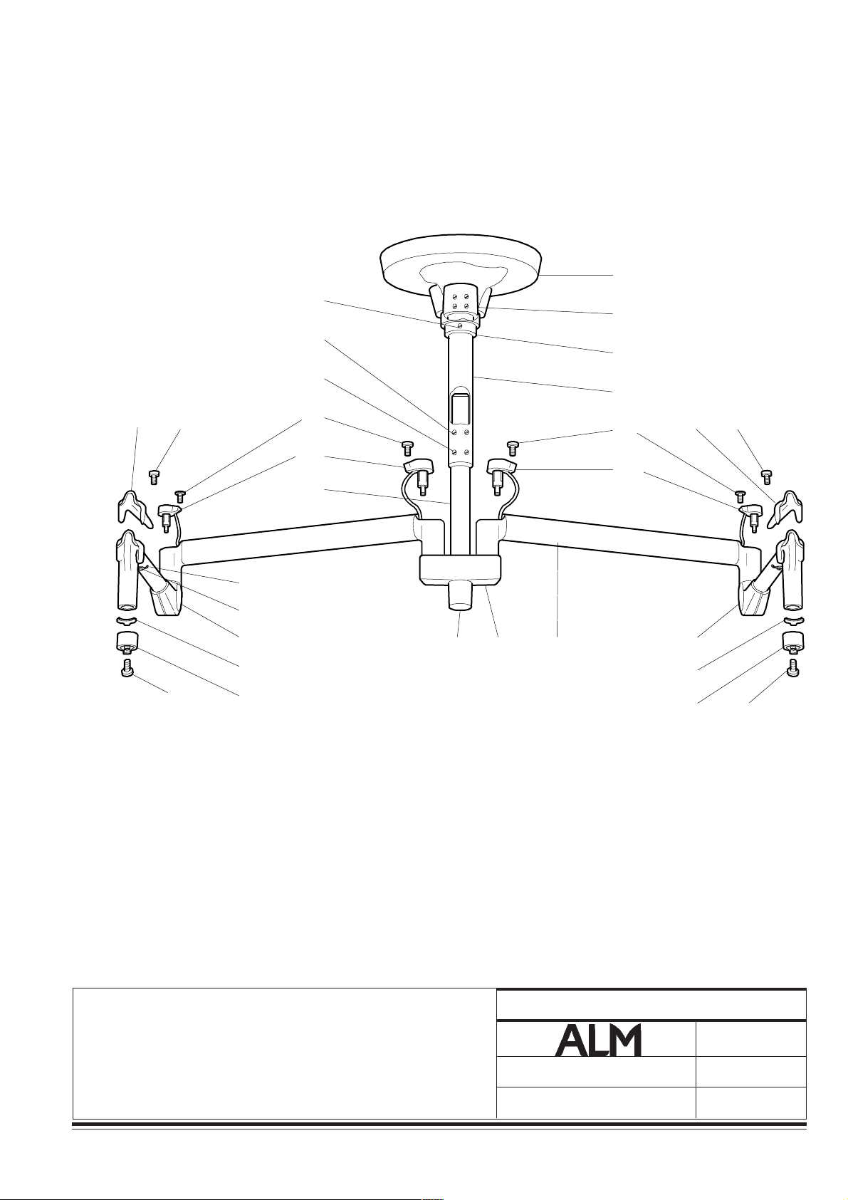
23
22
21
20
19
18
17
16
15
14
10
30
20
60
70
S
1
0
4
4
P
S
U
S
40
50
120 110 110
90
90
120
13
12
11
10
9
8
7
6
5
4
160
170
180
190
200210
100
80
130 140 150
100
180
190
200 210
3
2
1
I HGF E DCB A
SUSPENSION POUR AX4 DUO S
SUSPENSION FOR AX4 DUO S
AUFHÄNGUNG FÜR AX4 DUO S
010733003-3
Notice technique / Technical manual / Technische Anleitung
PLANCHE/DRAWING/ZEICHNUNG
Modif :
Änd :
010733003
15
02/00
Garreau
61

Éclairage opératoire
Surgical lighting system
OP-Leuchten
NOMENCLATURE 16 PLANCHE 16 SUSPENSION POUR AX4 M - DUO M
PARTS LIST 16 DRAWING 16 SUSPENSION FOR AX4 M - DUO M
STÜCKLISTE 16 ZEICHNUNG 16 AUFHÄNGUNG FÜR AX4 M - DUO M
PL. S/E REP. REFERENCE Qté
DR. S/A REF. REFERENCE DESIGNATION DESCRIPTION BESCHREIBUNG Qty
DA UBG ORTZ KENNZEICHEN Mg
10A, 20A 567201995 Support mural Spacer Wandabstützung
y
30A,40A,50A 567202995 Bras principal Main arm Hauptarm
y
60A à 110A 567214995 Bras d'équilibrage PRX PRX balancing arm Ausgleicharm PRX
y
60A à 110A 187104 Bras d'équilibrage AX AX balancing arm Ausgleicharm AX
y
40A 67208555 Jeu de réparation contact Repair kit for rotating Reparatursatz für
tournant bras d'équilibrage contact balancing arm Drehkontakt des
Ausgleicharms
62
010733003-3
010733003 Notice technique / Technical manual / Technische Anleitung
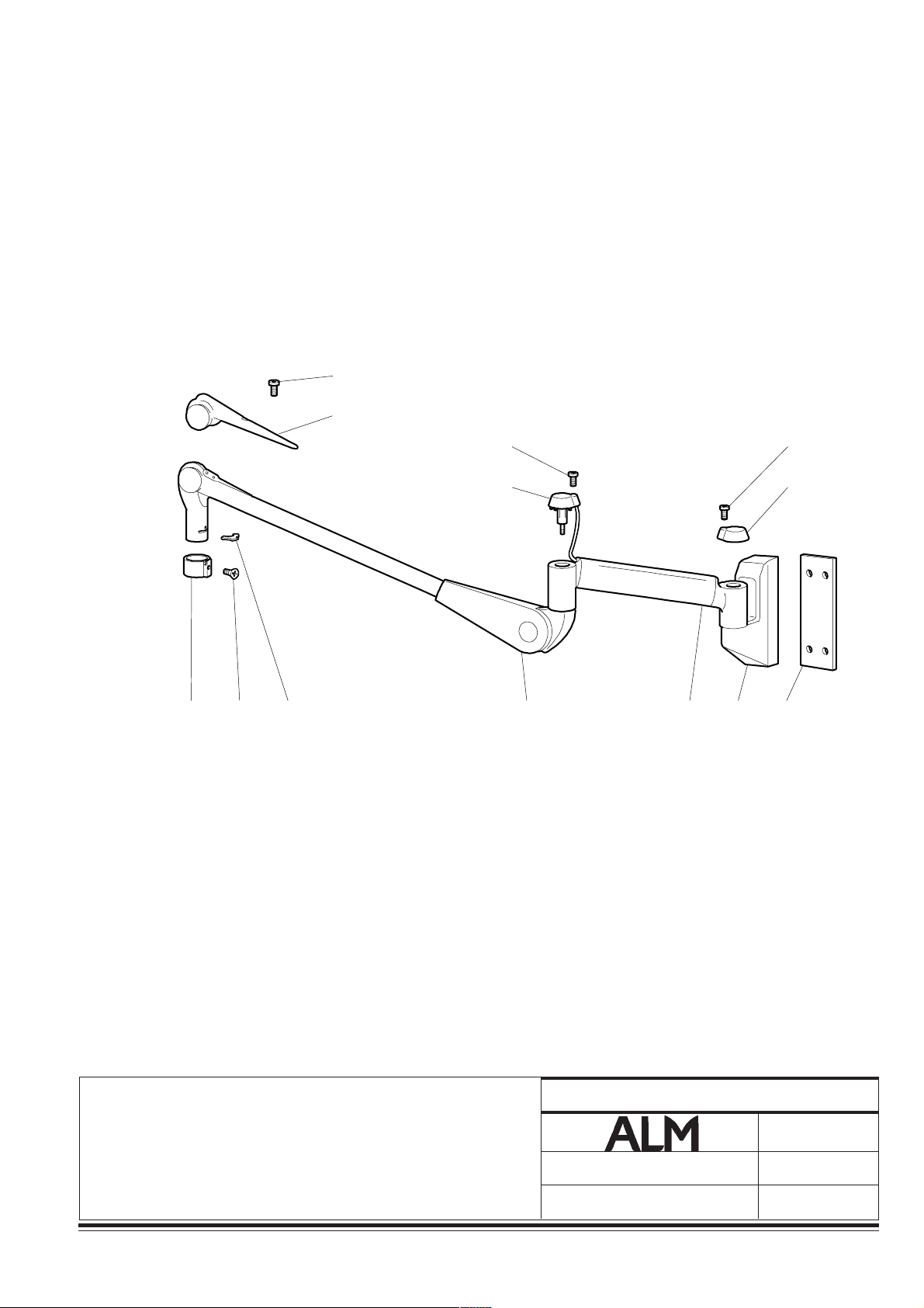
23
22
21
20
19
18
17
16
15
14
13
12
11
10
9
8
7
70
80
50
40
110 100 90 60 30 20 10
50
40
2
0
0
4
P
S
U
S
6
5
4
3
2
1
I HGF E DCB A
SUSPENSION POUR AX4 M - DUO M
SUSPENSION FOR AX4 M - DUO M
AUFHÄNGUNG FÜR AX4 M - DUO M
010733003-3
Notice technique / Technical manual / Technische Anleitung
PLANCHE/DRAWING/ZEICHNUNG
Modif :
Änd :
010733003
16
02/00
Garreau
63

Éclairage opératoire
Surgical lighting system
OP-Leuchten
Interventions spécifiques Specific interventions Spezifische Eingriffe
Date Nature Nom de l'entreprise Nom du technicien Visa
Date Nature Company name Technician name Signature
Datum Ursache Name des Unternehmens Name des Technikers Unterschrift
64
010733103-3
010733103 Notice technique / Technical manual / Technische Anleitung

Éclairage opératoire
Surgical lighting system
OP-Leuchten
1 an year Jahr Date de la révision : _____________ Nom de l'entreprise : ____________________
Service date : __________________ Company name : _______________________
Datum der Wartung : ____________ Name des Unternehmens : ______________
Nom du technicien : _______________________ Visa : _________________
Technician name : ________________________ Signature : _____________
Name des Technikers : ____________________ Unterschrift : ___________
Remarques suite à la révision, nature des réparations effectuées et pièces changées :
Comments after the service, nature of repairs made and parts changed:
Anmerkungen bezüglich der Wartung, Ursache der Wartung und ausgewechselte Teile:
2 ans years Jahre Date de la révision : ___________ Nom de l'entreprise : ____________________
Service date : _________________ Company name : _______________________
Datum der Wartung : ___________ Name des Unternehmens : ______________
Nom du technicien : _______________________ Visa : _________________
Technician name : ________________________ Signature : _____________
Name des Technikers : ____________________ Unterschrift : ___________
Remarques suite à la révision, nature des réparations effectuées et pièces changées :
Comments after the service, nature of repairs made and parts changed:
Anmerkungen bezüglich der Wartung, Ursache der Wartung und ausgewechselte Teile:
3 ans years Jahre Date de la révision : ___________ Nom de l'entreprise : ____________________
Service date : _________________ Company name : _______________________
Datum der Wartung : ___________ Name des Unternehmens : ______________
Nom du technicien : _______________________ Visa : _________________
Technician name : ________________________ Signature : _____________
Name des Technikers : ____________________ Unterschrift : ___________
Remarques suite à la révision, nature des réparations effectuées et pièces changées :
Comments after the service, nature of repairs made and parts changed:
Anmerkungen bezüglich der Wartung, Ursache der Wartung und ausgewechselte Teile:
4 ans years Jahre Date de la révision : ___________ Nom de l'entreprise : ____________________
Service date : _________________ Company name : _______________________
Datum der Wartung : ___________ Name des Unternehmens : ______________
Nom du technicien : _______________________ Visa : _________________
Technician name : ________________________ Signature : _____________
Name des Technikers : ____________________ Unterschrift : ___________
Remarques suite à la révision, nature des réparations effectuées et pièces changées :
Comments after the service, nature of repairs made and parts changed:
Anmerkungen bezüglich der Wartung, Ursache der Wartung und ausgewechselte Teile:
010733103-3
Notice technique / Technical manual / Technische Anleitung
010733103
65

Éclairage opératoire
Surgical lighting system
OP-Leuchten
5 ans years Jahr Date de la révision : _____________ Nom de l'entreprise : ____________________
Service date : __________________ Company name : _______________________
Datum der Wartung : ____________ Name des Unternehmens : ______________
Nom du technicien : _______________________ Visa : _________________
Technician name : ________________________ Signature : _____________
Name des technikers : _____________________ Unterschrift : ___________
Remarques suite à la révision, nature des réparations effectuées et pièces changées :
Comments after the service, nature of repairs made and parts changed:
Anmerkungen bezüglich der Wartung, Ursache der Wartung und ausgewechselte Teile:
6 ans years Jahr Date de la révision : ___________ Nom de l'entreprise : ____________________
Service date : _________________ Company name : _______________________
Datum der Wartung : ___________ Name des Unternehmens : ______________
Nom du technicien : _______________________ Visa : _________________
Technician name : ________________________ Signature : _____________
Name des technikers : _____________________ Unterschrift : ___________
Remarques suite à la révision, nature des réparations effectuées et pièces changées :
Comments after the service, nature of repairs made and parts changed:
Anmerkungen bezüglich der Wartung, Ursache der Wartung und ausgewechselte Teile:
7 ans years Jahr Date de la révision : ___________ Nom de l'entreprise : ____________________
Service date : _________________ Company name : _______________________
Datum der Wartung : ___________ Name des Unternehmens : ______________
Nom du technicien : _______________________ Visa : _________________
Technician name : ________________________ Signature : _____________
Name des technikers : _____________________ Unterschrift : ___________
Remarques suite à la révision, nature des réparations effectuées et pièces changées :
Comments after the service, nature of repairs made and parts changed:
Anmerkungen bezüglich der Wartung, Ursache der Wartung und ausgewechselte Teile:
8 ans years Jahr Date de la révision : ___________ Nom de l'entreprise : ____________________
Service date : _________________ Company name : _______________________
Datum der Wartung : ___________ Name des Unternehmens : ______________
Nom du technicien : _______________________ Visa : _________________
Technician name : ________________________ Signature : _____________
Name des technikers : _____________________ Unterschrift : ___________
Remarques suite à la révision, nature des réparations effectuées et pièces changées :
Comments after the service, nature of repairs made and parts changed:
Anmerkungen bezüglich der Wartung, Ursache der Wartung und ausgewechselte Teile:
66
010733103 Notice technique / Technical manual / Technische Anleitung
010733103-3

Éclairage opératoire
Surgical lighting system
OP-Leuchten
9 ans years Jahr Date de la révision : ___________ Nom de l'entreprise : ____________________
Service date : _________________ Company name : _______________________
Datum der Wartung : ___________ Name des Unternehmens : ______________
Nom du technicien : _______________________ Visa : _________________
Technician name : ________________________ Signature : _____________
Name des technikers : _____________________ Unterschrift : ___________
Remarques suite à la révision, nature des réparations effectuées et pièces changées :
Comments after the service, nature of repairs made and parts changed:
Anmerkungen bezüglich der Wartung, Ursache der Wartung und ausgewechselte Teile:
10 ans years Jahr Date de la révision : ___________ Nom de l'entreprise : ____________________
Service date : _________________ Company name : _______________________
Datum der Wartung : ___________ Name des Unternehmens : ______________
Nom du technicien : _______________________ Visa : _________________
Technician name : ________________________ Signature : _____________
Name des technikers : _____________________ Unterschrift : ___________
Remarques suite à la révision, nature des réparations effectuées et pièces changées :
Comments after the service, nature of repairs made and parts changed:
Anmerkungen bezüglich der Wartung, Ursache der Wartung und ausgewechselte Teile:
Contacter la société ALM pour obtenir un nouveau carnet de suivi de révisions, ainsi qu'un
nouveau document de maintenance périodique.
Contact ALM to obtain a new service handbook and a new periodic maintenance document.
Wir bitten Sie, sich mit uns in Verbindung zu setzen, um ein neues Wartungsheft und ein neues
periodisches Wartungsdokument zu erhalten.
010733103-3
Notice technique / Technical manual / Technische Anleitung
010733103
67

Notre réseau reste à votre entière disposition pour
répondre à vos questions.
Our network is at your disposal if you have any queries.
Bei Fragen richten Sie sich bitte an unser Netz. Wir
beraten Sie gerne.
ISO 9001
Certificat
Certificate
Zertifikat
AFAQNr.1989-032
ALM
Parc de Limère - rue de la pomme de pin - ARDON 45074 ORLÉANS CEDEX 2 - FRANCE
Tél. 02.38.25.88.88 - Fax 02.38.25.88.00
 Loading...