


GE 6610 AC-1


Reporting an ac cident or incident
Use this information when reporting incidents and
accidents involving the unit.
If an ac cident or an in cident ass ociated with the occu rs, this must be
reported immediately in writing to the address below. The report must
be used to identify the cause of the accident or incident and to what
extent the occurrence was due to t he unit
The unit is a product in the Getinge range.
The unit may also be a ster ilizer that is a medical engineering product
and which confo rms to the EU medic al devices direc tive, or wh ich is
constr ucted in a sim ilar way t o a medical device. U nder the m edical
devic es direc tive, the manufac turer must investi gate the cause of
accidents/incidents that occur and report them to the authorities
concerned.
The investigation may lead to changes in new or already delivered
devices or in instructions and guidance.
The following circumstances must be reported:
1. circumstances that caused the death of a patient, user or someone
else, or that caused serious deterioration in the health of a patient,
user or someone else.
2. circumstances that might have caused, the death of a patient, user or
someone else, or that might have caused serious deterioration in the
health of a patient, user or someone else.
The following info rma tio n is requ ir ed:
The manufacturing number of the unit (on a label in the electrical
cabinet), Date/time of event, Description of event, Consequences of
event.
Contact: Name, Phone number, Address:, E-mail:
The information must be sent by letter or fax to:
GETINGE STERILIZATION AB
For the attention of: Quality Manager
Box 69
31044 GETINGE
Sweden
Fax: +46 (0)35 549 52

Attention symbols
I Some of the warnings, instructions and advice in this manual are so
important that we used the following special symbols to draw attention
to them. The symbols used are as follows:
Warnings
This symbol indicates a warning in the text of the manual.
The nature of what the warning relates to is such that it
may result in more or less severe injury and in certain
cases mortal danger.
The symbol is also used to highlight safety components,
etc. See “Safety devices - an overview” under
“Introduction” in the DESCRIPTION OF OPERATION or
under “Maintenance” in the SERVICE MANUAL.
Instructions
This symbol highlights instructions that are important for
avoiding damage to the unit and/or load, among other
things.
Advice
This symbol indicates important advice and hints that
make it easier to work with the unit.
Symbols on t he unit
Hot surface
This symbol gives warning of a hot surface.
S
SS

SERVICEMANUAL
TABLE OF CONTENTS
INSTALLATION . . . . . . . . . . . . . . . . . . . . . . . . . . . . . . . . . . . . . . . . . . . . . . .7
Genera l requirements to be me t b y the i n stallatio n l o c a t i o n. . . . . . . . . . . . . . . . . . . . 7
Unpac k i n g . . . . . . . . . . . . . . . . . . . . . . . . . . . . . . . . . . . . . . . . . . . . . . . . . . . . . . . . . . 9
Storage. . . . . . . . . . . . . . . . . . . . . . . . . . . . . . . . . . . . . . . . . . . . . . . . . . . . . . . . . . . . . 9
Instal l a t i o n. . . . . . . . . . . . . . . . . . . . . . . . . . . . . . . . . . . . . . . . . . . . . . . . . . . . . . . . . . 9
Connection. . . . . . . . . . . . . . . . . . . . . . . . . . . . . . . . . . . . . . . . . . . . . . . . . . . . . . . . . 10
Electrical . . . . . . . . . . . . . . . . . . . . . . . . . . . . . . . . . . . . . . . . . . . . . . . . . . . . . . . . . . 10
ESD (Ele ctrosta t i c discharge ) . . . . . . . . . . . . . . . . . . . . . . . . . . . . . . . . . . . . . . . . . . 12
Incoming media. . . . . . . . . . . . . . . . . . . . . . . . . . . . . . . . . . . . . . . . . . . . . . . . . . . . . 14
Connecting water. . . . . . . . . . . . . . . . . . . . . . . . . . . . . . . . . . . . . . . . . . . . . . . . . . . . 15
Steam . . . . . . . . . . . . . . . . . . . . . . . . . . . . . . . . . . . . . . . . . . . . . . . . . . . . . . . . . . . . . 17
Compressed air quality . . . . . . . . . . . . . . . . . . . . . . . . . . . . . . . . . . . . . . . . . . . . . . . 23
Air connection . . . . . . . . . . . . . . . . . . . . . . . . . . . . . . . . . . . . . . . . . . . . . . . . . . . . . . 24
Drain . . . . . . . . . . . . . . . . . . . . . . . . . . . . . . . . . . . . . . . . . . . . . . . . . . . . . . . . . . . . . 25
Outlet fro m safety val v e . . . . . . . . . . . . . . . . . . . . . . . . . . . . . . . . . . . . . . . . . . . . . . 26
Ventilation. . . . . . . . . . . . . . . . . . . . . . . . . . . . . . . . . . . . . . . . . . . . . . . . . . . . . . . . . 26
Response for pressure vessel and safety valves . . . . . . . . . . . . . . . . . . . . . . . . . . . . 27
Functio n al check-up prio r t o us e. . . . . . . . . . . . . . . . . . . . . . . . . . . . . . . . . . . . . . . . 28
FUNCTION CHECK. . . . . . . . . . . . . . . . . . . . . . . . . . . . . . . . . . . . . . . . . . . .29
Before u se . . . . . . . . . . . . . . . . . . . . . . . . . . . . . . . . . . . . . . . . . . . . . . . . . . . . . . . . . 29
MAINTENANCE . . . . . . . . . . . . . . . . . . . . . . . . . . . . . . . . . . . . . . . . . . . . . .31
Overvi e w o f safety devices . . . . . . . . . . . . . . . . . . . . . . . . . . . . . . . . . . . . . . . . . . . . 31
Maint e n an c e p l an . . . . . . . . . . . . . . . . . . . . . . . . . . . . . . . . . . . . . . . . . . . . . . . . . . . . 32
Cycle counter. . . . . . . . . . . . . . . . . . . . . . . . . . . . . . . . . . . . . . . . . . . . . . . . . . . . . . . 36
The ECO wa t e r-saving sy stem . . . . . . . . . . . . . . . . . . . . . . . . . . . . . . . . . . . . . . . . . 37
ADVICE AND INSTRUCTIONS. . . . . . . . . . . . . . . . . . . . . . . . . . . . . . . . . .41
Manual i n t e rv entions in the process . . . . . . . . . . . . . . . . . . . . . . . . . . . . . . . . . . . . . 41
Manual steppi n g wit h k e y sw i t c h. . . . . . . . . . . . . . . . . . . . . . . . . . . . . . . . . . . . . . . . 41
Faulty a n a l o g se n so r . . . . . . . . . . . . . . . . . . . . . . . . . . . . . . . . . . . . . . . . . . . . . . . . . 42
Press u re sensor fault . . . . . . . . . . . . . . . . . . . . . . . . . . . . . . . . . . . . . . . . . . . . . . . . . 42
Manual control b y man u a l l y a c t u ating the con trol val v es. . . . . . . . . . . . . . . . . . . . . 42
Extern a l sa fety inte rl o c k fau lt . . . . . . . . . . . . . . . . . . . . . . . . . . . . . . . . . . . . . . . . . . 43
Backup battery fault . . . . . . . . . . . . . . . . . . . . . . . . . . . . . . . . . . . . . . . . . . . . . . . . . 44
Restoring softw a re from E-PROM (cold st a r t) . . . . . . . . . . . . . . . . . . . . . . . . . . . . . 45
Manual door opening. . . . . . . . . . . . . . . . . . . . . . . . . . . . . . . . . . . . . . . . . . . . . . . . . 46
Power failure alarm with door open . . . . . . . . . . . . . . . . . . . . . . . . . . . . . . . . . . . . . 46
User-p ro gramma b l e fu n ctions. . . . . . . . . . . . . . . . . . . . . . . . . . . . . . . . . . . . . . . . . . 46
Safety v a l v e check. . . . . . . . . . . . . . . . . . . . . . . . . . . . . . . . . . . . . . . . . . . . . . . . . . . 50
THE DOOR . . . . . . . . . . . . . . . . . . . . . . . . . . . . . . . . . . . . . . . . . . . . . . . . . . . 53
General . . . . . . . . . . . . . . . . . . . . . . . . . . . . . . . . . . . . . . . . . . . . . . . . . . . . . . . . . . . 53
Seal between door and chamber . . . . . . . . . . . . . . . . . . . . . . . . . . . . . . . . . . . . . . . . 53
Media to t h e c h a m b e r . . . . . . . . . . . . . . . . . . . . . . . . . . . . . . . . . . . . . . . . . . . . . . . . 54

Checking the door action . . . . . . . . . . . . . . . . . . . . . . . . . . . . . . . . . . . . . . . . . . . . . 54
Checking and adjusting the door position. . . . . . . . . . . . . . . . . . . . . . . . . . . . . . . . . 54
Remov ing t h e d o or . . . . . . . . . . . . . . . . . . . . . . . . . . . . . . . . . . . . . . . . . . . . . . . . . . 5 7
The door seal. . . . . . . . . . . . . . . . . . . . . . . . . . . . . . . . . . . . . . . . . . . . . . . . . . . . . . . 59
Lubrication and replacement of the door seal. . . . . . . . . . . . . . . . . . . . . . . . . . . . . . 60
Replacing the door cylinder . . . . . . . . . . . . . . . . . . . . . . . . . . . . . . . . . . . . . . . . . . . 62
Repla ci n g th e p i st o n se a l. . . . . . . . . . . . . . . . . . . . . . . . . . . . . . . . . . . . . . . . . . . . . . 63
Door safety arran g e m e n t s . . . . . . . . . . . . . . . . . . . . . . . . . . . . . . . . . . . . . . . . . . . . . 64
Blocking the start and opening the door . . . . . . . . . . . . . . . . . . . . . . . . . . . . . . . . . . 66
Blocking the media supply to the chamber. . . . . . . . . . . . . . . . . . . . . . . . . . . . . . . . 67
Safety interlocking of the door opening . . . . . . . . . . . . . . . . . . . . . . . . . . . . . . . . . . 69
CONTROL UNIT PACS 3000. . . . . . . . . . . . . . . . . . . . . . . . . . . . . . . . . . . . 7 3
Operat i n g p a n el ty p e O P 30 . . . . . . . . . . . . . . . . . . . . . . . . . . . . . . . . . . . . . . . . . . . 7 6
Indica t o rs and contr o l s . . . . . . . . . . . . . . . . . . . . . . . . . . . . . . . . . . . . . . . . . . . . . . . 7 6
Displ a y . . . . . . . . . . . . . . . . . . . . . . . . . . . . . . . . . . . . . . . . . . . . . . . . . . . . . . . . . . . 77
Operat o r menu tree . . . . . . . . . . . . . . . . . . . . . . . . . . . . . . . . . . . . . . . . . . . . . . . . . . 8 1
Descr i p t ion o f operator menu tree . . . . . . . . . . . . . . . . . . . . . . . . . . . . . . . . . . . . . . . 81
Syste m m en u . . . . . . . . . . . . . . . . . . . . . . . . . . . . . . . . . . . . . . . . . . . . . . . . . . . . . . . 84
I2C-link faults on PACS 3000 modules.. . . . . . . . . . . . . . . . . . . . . . . . . . . . . . . . . . 89
Technical data, PACS 3000 . . . . . . . . . . . . . . . . . . . . . . . . . . . . . . . . . . . . . . . . . . . 93
COMPONENTS. . . . . . . . . . . . . . . . . . . . . . . . . . . . . . . . . . . . . . . . . . . . . . . 97
Illust ration on d raw i n g s. . . . . . . . . . . . . . . . . . . . . . . . . . . . . . . . . . . . . . . . . . . . . . . 9 7
Panel-mounted printer. . . . . . . . . . . . . . . . . . . . . . . . . . . . . . . . . . . . . . . . . . . . . . . . 97
Vacuu m pum p LEM 50. . . . . . . . . . . . . . . . . . . . . . . . . . . . . . . . . . . . . . . . . . . . . . 104
Pressure transmitter. . . . . . . . . . . . . . . . . . . . . . . . . . . . . . . . . . . . . . . . . . . . . . . . . 110
Single circuit pressure switch 469 56 96. . . . . . . . . . . . . . . . . . . . . . . . . . . . . . . . . 110
Soleno i d valves . . . . . . . . . . . . . . . . . . . . . . . . . . . . . . . . . . . . . . . . . . . . . . . . . . . . 112
Pt 100 sensor (RTD) . . . . . . . . . . . . . . . . . . . . . . . . . . . . . . . . . . . . . . . . . . . . . . . . 113
Piston v alves . . . . . . . . . . . . . . . . . . . . . . . . . . . . . . . . . . . . . . . . . . . . . . . . . . . . . . 114
Filters and strainers. . . . . . . . . . . . . . . . . . . . . . . . . . . . . . . . . . . . . . . . . . . . . . . . . 115
Restr i c t o rs . . . . . . . . . . . . . . . . . . . . . . . . . . . . . . . . . . . . . . . . . . . . . . . . . . . . . . . . 115
Soldered plate-type heat exchangers . . . . . . . . . . . . . . . . . . . . . . . . . . . . . . . . . . . 116
SCRAPPING INSTRUCTION . . . . . . . . . . . . . . . . . . . . . . . . . . . . . . . . . . 119

INSTALLATION
This pre-installation instruction covers the information needed to prepare the installation site, before delivery of the unit.
With the delivery of the machi ne a specific installation instruction will
be enclosed. A copy of the s pecific instruction is als o enclosed in the
manual.
The specific instruction may also cover details such as:
• Unpacking
• Rigging and transportation within the facility
• Reassembly of the dismounted equipment
• Functional test prior to use.
General requirements to be met by the installation
location
Use Ge tinge St eriliza tion AB’s instal lation d rawings for desig n and
building purposes when determining the necessary dimensions and
design. Experience has shown that particular attention should be paid to
the following points.
• The ceiling height in the service room must be sufficient to allow
space for all equipment according to the installation drawing.
• The service room must have good lighting and be ventilated. For
requirements regarding ventilation, see the special section on this
topic in this instruction manual.
• All dimensions relating to foundations, floor pits, wall openings, etc.
refer to finished dimensions. These dimensions must be complied
with when floor, wall and ceiling linings have been installed.
• When choosing the wall covering in the service room it should be
kept in mind that the room may be filled with steam the event of a
failure.
• The equipment must be set up so that the distance to the nearest
workplace or treatment position is more than 1.5 meters (5 foot).
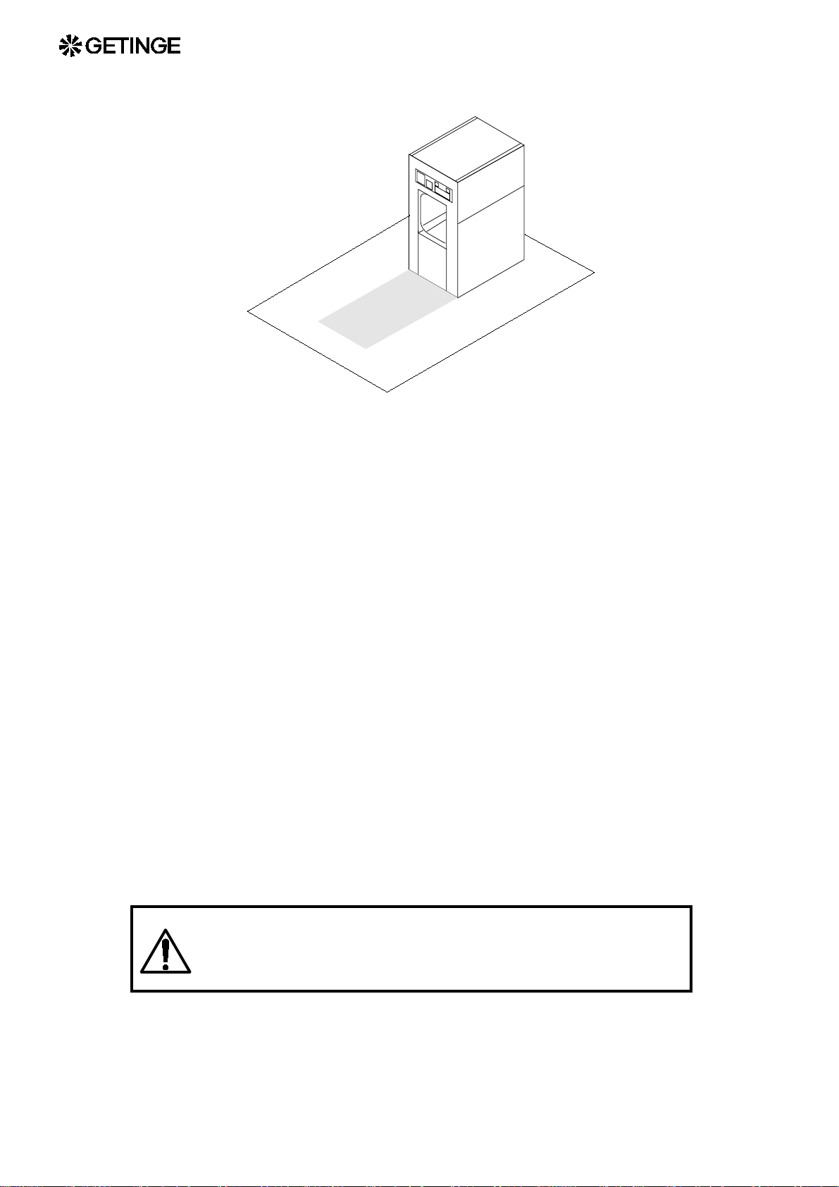
• The floor in front of the door( s) of the sterilizer must be flat and level
within in a zone as shown in the diagram below. When installing
several steriliz ers that are to be served by a common loader, the
width of this area must be the same as that of the entire installation.
7
These requirements, and others such as those relating to floor
loading, are specified in more detail on the installation drawing.
Installing a sterilizer in a wall opening
• There must be no trim, baseboards or similar objects within
approximately 5 centimeters (2 inch) from the edge of the opening
next to the wall opening for building in the sterilizer.
• Sterilizers installed in wall openings should be sealed to the wall in
order to separate the sterile and non-sterile sides. The edges of the
wall opening and the transition between the front plates of the
sterilizer and the wall should be finished in a properly hygienic
manner.
• Sterilizers with vertically-operating doors: These models have a
generous gap between the front plates of the sterilizer and the wall
opening. The gap must be covered with suitable fitting pieces.
Getinge sells an add-on system for this purpose.
• Sterilizers with horizontally-operating doors There are two
variants: either the front plates are designed to lie outs ide and overlap
the wall, or a gap is left between the wall and the plates. The version
with the gap must be sealed with silicone compound or similar . The
outside of the front plates meets the wall in this version so that a
smooth transition is obtained. The installation drawing shows the
specific installation method for a particular sterilizer.
Find out the central point of gravity when lifting and transporting a packed or not pa cked ster ilizer th ere by avoidi ng
serious accidents.
8

Unpacking
• Check when unpacking the equipment that the order No. of its data
plate conforms with the ordering No. of the documents.
• Check that the sterilizer is faultless. Any transportation damage
should be reported within seven days to the transport company that
was responsible for delivery.
• Do not remove the protective plastic film from stainless st eel panels
until the installation is completed.
• There is certain equipment such as expendable items, control unit,
operating instruction and list of programs by-packed the sterilizer
inside the chamber. The two latter are to be posted where easily
observed by the operator at work.
Please note that those articles are adapted for each sterilizer. When unpacking more than one sterilizer the articles
are not to be interchanged.
Storage
Installation
The unit must be stored in a temperature between 2 and 40oC (35 and
105°F) and at a maximum relative humidity 95% (non-condensing).
• Observe national and local regulations concerning service space.
• Make sure that the clearance distances required by health and safety
regulations are provided.
9
Connection
Certain types of installation work, water and electrical, for
example, should be done by authorized technicians.
If the work is not done properly, injury and damage may
result.
Faulty installation work invalidates the warranty on the
product supplied.
Pipework and electrical wiring should be done in a professional manner
so that the service compartment looks workmanlike and provides a
practical workplace which minimizes the risk of accidents.
• Find out the connection points and connection data of the equipment
by studying the installation drawings.
• Pay attention to local regulations.
• Remove debris by flushing or blowing t hrough all pipes that will be
connected.
Electrical
• Insulate hot and very cold pipes.
• Mark pipes and electrical wiring.
Install shut-o ff devices in the media supp ly lines near ea ch
unit, so that the operator can use them without passing
through a risk area. The inner part of the service
compartment is not a suitable place for this.
Before welding on or near the sterilizer, ALL plug-in leads
must disconnected from ALL the PCBs of the control
system.
Components in the control system of the i nstallation and other electrical
components tolerate supply voltage variations of -10/+5 %. If greater
voltage variations are likely, a mains voltage stabilizer will have to be
provided between the ma ins cicuit breaker of the install ation and the
control equipment. As the equipment will present an inductive load to
the stabilizer, the stabilizer should be well oversized (at least 500 VA).
Permitted frequency deviation ±1%.
10
• Check that all terminal screws are tight..
General:Connect the equipment through a nearby multipole lockable, safety-marked switch to a three-phase
supply with non-disconnectible protective earth
conductor.
In the planning p has e: Con cernin g voltage and frequenc y,
mains cicuit breaker ratings and wiring sizes, see the
document “Technical data”.
When conne cting the equipm ent: connect a s show n on th e
wiring diagram. The drawing number is given in the
documentation of the equipment.
• If the building where the equipment is installed has a separate
equipotential bonding system, a wire must be run from this to the
earthing (grounding) terminal of the surge protection. The surge
protection is located in the terminal box. See the wiring diagram.
• If the control system of the equipment is to be connected to a
standalone computer, the power supply to the computer should be
taken from the the same distribution board as the equipment is
connected to. Common supply is important in order to avoid
potential differences and therefore the risk of damage to the
electronic circuits of the equipment.
• A printer used to print from the equipment must be
connected in accordance with the wiring diagram. Normally
it will take its supply directly from the electrical system of
the equipment. Some equipment has sockets for a printer. If
so, these are marked with the symbol for heavy current and
the text E110 and 230 V. The signal cable is connected to a
multipole socket marked E110.
• A printer used elsewhere must be powered from the same
distribution board as the equipment. Common supply is important in
order to avoid potential differences and therefore the risk of damage
to the electronic circuits of the equipment.
• The supply cable to the sterilizer should be run so that the
temperature rise in the cable due to its insulation and ambient
temperature remains within permissible limits.
• The routing and overcurrent protection of the supply cable must be
such that the sterilizer cannot be subjected to short-circuit currents
exceeding 6 kA.
• The following requirement is applicable in countries there IEC
61000-3-3 applies: Equipment with a current less than 16 Amps on
each phase which is supplied from a public power distribution
system applies to the directive. The public power distribution system
11
must at least be capabable to provide 100 Amps on each phase or
have a impedance of Z[ohm]=0,15+0,15*i.
• Load-breaking switches in accordance with IEC 898, with B or C
characteristic, are recommended for circuit protection. If such
switches are not available, protection can be provided by IEC 269-1
fuses, characteristics gG or gM.
• Vacuum pumps, fans, pumps and motors located in separate rooms
away from the common service area of the installation must have
their own individual multi- pole, lockable, safety-marked switches. A
switch of this description must always be installed close to the motor.
• Vacuum pumps and pumps for liquids: First make sure that the
feedwater tanks and pipework are filled with water. Th en check that
the direction of rotation of the pump is correct by briefly operating
the pump contactor by hand. Correct this as shown in the drawing
below.
Running the shaft seal dry could destroy it in just a few
seconds.
• Fans and three-phase motors: check that the direction of rotation
is correct by briefly operating the motor contactor by hand. Correct
this as shown in the drawing below.
• Correcting the direction of rotation: Swap two of the phase wires
in the supply cable between the motor and the contactor. For some
equipment the “contactor” may take form of a frequency converter
or soft-starter.
• It is recommended that the three-phase supply should be protected by
an earth leakage circuit breaker with a 300 mA trip current.
ESD (Electrostatic discharge)
ESD damage in in sta llatio n and ser vic ing may d estr oy the
electronic equipment. Read the instructions below
BEFORE starting work.
ESD damage
12
ESD is an overall term describing how electronic circuits a re damaged
by the static charging to w hich they are exposed when they come into
contact with electrically charged objects. Virtually all non-earthed
objects in the world around us have a static charge. Equipment and people are imperceptibly charged by friction in the air or between shoes and

floor in ordinary walking. This charge is transferred to the electronic
circuits when they are touched.
Any damage that occurs to the electronics may be difficult to de tect
and trace. It varies from immediate destruction of a circuit so that it no
longer works at all to insidiously affecting operation so that performance is not maintained. The circuits may even appear to be undamaged and then later disintegrate inexplicably.
Most replacements of electronic boards where the fault cannot be
explai ned and is bla med on uneven quality are probably du e to ESD
damage.
Requirements for protection in installation and servicing
GETINGE has ESD protection integrated into the production and testing of electronic equipment and also requires ES D protection to be used
after delivery for the warranty to apply.
Damage usually occurs after delivery if electronic boards are stored in
non-ESD-approved packs, if electronic boards are placed on non-ESDprotected work surfaces or if people not wearing ESD protection touch
them. Simple equipment can be obtained for all these situations which
prevents charging and theref ore ESD damage. Contact your local distributor of ESD protective equipment or GETINGE After Sales.
Practical requirem ents
Keep electronic boards only in screened and ESD-approved
•
(marked) bags.
• Use ESD pads connected to earth in accordance with the manufac-
turer's instructions to hold disassembled or new electronic boards
during assembly work.
• Do not touch electronic boards with tools that may be charged, e.g.
screwdrivers with a plastic or wooden handle. Use earthed tools if
necessary.
• Always use an ESD wrist band connected to earth in accordance with
the manufacturer's instructions when working in the electronic
enclosure or when handling boards.
• Newer keep foreign objects such as drawings or plastic pockets
inside the electronic box.
• Test the ESD protective equipment regularly.
13
Incoming media
General safety requirements for supply lines
The document Technical Data states permitted pressure levels for all
incoming media.
If the state d pressure of the me dium does not exce ed the design
pressure of the pressure vessel , the equipment does not normally have
protection against excessive pressure for that medium.
Where the supply medium pressure (as stated in Technical Data)
exceeds the design pressure of the pressure vessel, the equipment is
protected against exce ssive pressure for a well-define d inflow rate of
that medium. The protection takes the form of a specific safety valve
and suitable designed restrictions and valves in the internal pipework.
To ensure that the equipment is only supplied at the permitted
pressure levels, the user must accept liability for fitting the supply lines
with reducing valves and safety valves in accordance with the
regulations.
Whether or not the sterilizer is equipped with a safety
valve, the user must install correctly dimensioned safety
valves in the supply lines for incoming media.
Note that the pressure vessel safety systems cease to
operate if the pressure of any medium exceeds the range
stated in Connection data. This results in a RISK OF
BURSTING.
o
C (60°F). This temperature may be exceeded by 5°C (10°F) if reduced
depth of evacua tion and pump c apacity can b e accepted. This applies
primarily to sterilizers of the EN model, i.e. designed for the European
market.
Certain models intended primarily for tropical climates can easily be
modified for use with water temperatures up to 35oC (95°F). This topic
is covered under "Connection and pressures" in this section and in the
section headed "Customer-programmable functions" in the SERVICE
MANUAL.
HARDNESS
To minimise sterilizer service and maintenance costs, the water
hardness should not exceed 4dH / (0.7mmol/l) / (70 ppm). A water
softener is recommended where the water is harder than this.
14

Driving liquid for the vac uum pump
TEMPERATURE
The highest water temperature for maximum pump performance is 15
o
C. This temperature may be exc eeded by 5 degC if reduced depth of
evacuation and pump capacit y can be a ccepted. This appli es primarily
to sterilizers of the EN model, i.e. designed for the European market.
Certain models intended primarily for tropical climates can easily be
modified for use with water temperatures up to 35 oC. This topic is
covere d under "C onnecti on and pr essures" in this sec tion and in the
section headed "Customer-programmable functions" in the SERVICE
MANUAL.
HARDNESS
To minimise sterilizer service and maintenance costs, the water
hardness sh ould not exceed 4d H (0.7mmol/l). A w ater softener is
recommended where the water is harder than this.
Cooling water for heat exchangers
TEMPERATURE
The highest water temperature for satisfactory performance is 15oC
(60°F) . This temper ature may be e xceeded by 5°C (10°F) if reduced
performance is acceptable.
WATER QUALITY
To minimise service and maintenance costs, the water hardness should
not exceed 4dH / (0.7mmol/l) / (70 ppm). A water softener is
recommended where the wa ter is harder than this. The cooling water
must not be corrosive, nor must it contain s ubstances that are abrasi ve
or which form deposits. The water salt content should not be so high as
to cause scaling as a result of the temperature.
Connecting water
Common water supply
Some equipment in the basic version is supplied with water from a
single common connection to the sterilizer. T his means that the water
temperature and hardness are the same for all the water-using
equipment.
The water must always be colorless, with no solid contaminants such
as sand, f lakes of rust , graphite, e tc. The conte nt of other sub stances
may vary, as previously mentioned, and the temperature should be
suited to the require ments of the vacuum pum p sealing w ater. If the
sterilizer is connected to the drinking w ater supply, requi rements for
15
Back flow prevention must be observed; see Connecting with reverse
siphon protection.
Connection with reverse siphon protection
Any connec tions made to a dri nking water suppl y must comply with
national and local regulations. In countries where EU regulations apply,
the national requirements will gradually be complemented by
harmonis ed EN stan dards, r egulating the con nection and presc ribing
equipment for such purposes as reverse siphon protection.
Reverse siphon protection
When the equipment is instal led, an appr oved (and , in certai n cases ,
type-tested) reverse-siphon prote ction device must be fitted in the
supply line. Details of the particular types of rever se siphon protection
devices that must be used, and how they must be installed, are regulated
by the responsible authorities in each country.
• In the absence of specific rules for connection, we recommend that a
connection to the drinking water supply should be arranged as
follows:
5
6
2
1
4
3
H > 300 mm
7
1 Main supply line 2 Shut-off valve
3 Filter 4 Non-return valve
5 Pressure gauge,
including water
pockets and
6 Reverse siphon protection
7 Connection to sterilizer
isolating valve
• The above components should be supplied by the customer unless
the contract states otherwise.
Pressure
16
For service water systems: Normally the equipment is supplied via
•
a shutoff valve to a water pipe syst em with a positive p ressure of 3.5
to 6 bar(e), equivalent to 350 to 600 kpa(e) or 50 to 90 psig. Models
for certain markets and models that can be converted for tropical
conditions can be connected to pipe systems with a pressure as low
as 1.0 bar(e), equivalent to 100 kpa(e) or 15 psig. Precise information
about pressures, temperatures, consumption rates and connection
size for each medium is given in the Technical Data document. In
case of doubt, Technical Data always takes precedence.
• For closed systems: Normally the equipment is supplied via a
shutoff valve to a circulating system with a positive pressure of 3.5
to 6 bar(e), equivalent to 350 to 600 kpa(e) or 50 to 90 psig. Note that
the pressure in the return line must normally be at least 1.0 bar lower,
equivalent to 100 kpa lower or 15 psi lower . Precise information
about pressures, temperatures, consumption rates and connection
size for each medium is given in the Technical Data document. In
case of doubt, Technical Data always takes precedence.
The Technica l Data d ocu me nt st ate s a per mi tted pressu re
range for all incoming media. Always check that the
equipment is connected to supply lines in which the
pressure is within the correct range.
Note that the pressure vessel safety systems cease to
operate if the pressure of any medium exceeds the range
stated in Technical Data. This results in a RISK OF
BURSTING!
Steam
The result of a sterilization is very dependent on the nature of the
steam used. The steam must therefore meet certain quality
requirements.
Steam generators based upon evaporation from high pressure hot
water should not be used since the steam produced is of inferior quality
for sterilization purposes.
Minimum cleanness requirements
The following are minimum cleanness requirements, but may be
regarded as normal requirements to be met by steam for heating in heat
exchangers and jackets. It is the user’s responsibility to choose the
steam quality for sterilization, taking account of local regulations and
official require me n ts .
1. Solid particles such as welding pellets, graphite, rust flakes, sand
etc must not occur, since the steam comes into physical contact with
the goods to be sterilized. These impurities may also block steam
traps and chokes.
17

2. For the same reason, liquids must not occur, except very small
amounts of water.
3. Gases will prevent close contact between the steam and the microorganisms to be killed. They must be kept below the proportions
below.
· Hydrazine (N2H4) max 0.11 mg/kg (ppm) steam.
· Ammonia (NH3) max 5 mg/kg (ppm) steam.
· Air and/or non-condensable gases max 7 ml (0.25 oz) per 200 ml
(6.75 oz) condensate, formed by the steam-air/gas mixture.
4. Other chemicals such as softener residue and similar substances
must not occur in sterilizing steam.
· Salt content max 1 mg/kg (ppm) steam.
Analysis of condensate
An analysis of the condensate f rom the steam gives an idea of its
cleanness as regards other substances. These substance should not occur
in concentrations exceeding the values given in mg/kg condensate in the
table below.
Evaporation residues 1.0 mg/l (ppm), of which:
Silicon in the form of SiO
Iron 0.1 mg/kg (ppm)
Cadmium 0.005 mg/kg (ppm)
Lead 0.05 mg/kg (ppm)
Other heavy metals 0.1 mg/kg (ppm)
Chlorides 0.1 mg/kg (ppm)
Phosphates 0 mg/kg (ppm)
Recommended pH = 5 - 7
Suitable conductivity < 3 µS/cm [at 20 °C (68°F)]
Suitable hardness ≤ 0.1 dH (1.8 ppm)
Steam of the quality specified below under Process steam is
recommended for the sterilization of products that come into direct or
indirect contact with the human blood circulation, where there are very
stringent requirements for cleanness.
2
0.01 mg/kg (ppm)
Process steam
18
In accordance with cGMP, the chemical content of the steam must
conform to the requirements for WFI of the European Pharmacopoeia
Pressure
(EP) 3rd edition 1997, United States Pharmacopoeia (USP XXIII) and/
or another local pharmacopoeia.
Alternatively, st eam wi th a chemical content equivalent to clean steam
for ster ilization as p er HTM 2031 may be used if the use r’s local
regulations and official requirements allow it.
A See the document “Technical Data” for correct information about
steam p r e ssure.
If the steam supply line pressure exceeds the steam
pressure stated in Con nection d ata, th e user must in stall a
pressure reduction unit with a suitable safety valve which
has sufficient blow-off capacity for the amount of steam
supplied.
B Permitted pressure variations max ± 0.1 bar (equivalent to ±10.0
kPa or ± 1.5 psi).
Moisture content
Sterilizer s should be supplied with dry s aturated steam. The ideal
physical state “dry saturated” is difficult to maintain in a practical
application, and measurement/control of the moisture content of the
steam is tricky .
Applying the adv ice given below, which is based upon practical
experience, will generally result in steam with a satisfactory moisture
content. This means that it is not superheated either. Superheating of the
steam is highly undesirable in connection with sterilization because it
does not con tribute the humidification necessary to kill microorganisms.
Methods and values for determining the quality of the steam and the
degree of superheating are described in standard EN285, for instance.
Practical arrangements
1. Connect the equipment to a line in which steam is consumed
continuously. Long branch connections should be avoided.
2. Choose the appropriate pipe size from the table below. If more than
one piece of equipment is connected to the same line, a diversity
factor of 0.8 or higher may be applied.
Steam pressure Highest design gas velocity
19
2.5 [bar (e)], 36 [psig] 38 [m/s], 125 [feet/s]
3 [bar (e)], 45 [psig] 35 [m/s], 115 [feet/s]
4.5 [bar (e)], 65 [psig] 30 [m/s], 100 [feet/s]
6 [bar (e)], 90 [psig] 25 [m/s], 80 [feet/s]
The specific steam pressur e of the equipment is given in the
document “Technical Data”. If the installation is to be connected to
a steam supply at a different pressure, the table can be used for
guidance. If in doubt, contact Getinge Sterilization AB.
3. The steam supply pipes should have a fa ll of at least 1:50 (1/4 inch
per foot) in the direction of flow.
4. Install reducing valve(s) in the supply line if the pressure is higher
than that specified in Technical Data. The steam pressure upstream
of the reducing valve should not fluctuate more than 10%.
Do not reduce the pressure by a factor s maller than 0. 5 in one step.
Use a second reducing valve for greater reduction ratio. Each
reducing valve must be followed by a safety valve.
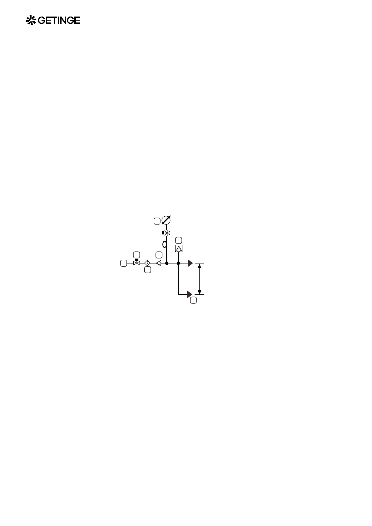
If the steam in the supply line is wet, include condensate
removal as shown in Figure "A" just before the reducing
valve, as shown in the sketches below.
The drain line of safety valves should have at least the same
dimension as the valve blowoff opening and must not contain shut
off devices or chokes. Water pockets formed in the piping, must be
drained.
5. There must be no chokes or restrictions placed in horizontal pipes.
6. Fit the last reducing valve not more than 6 m (20 ft) pipe length
away from the sterilizer, but not closer than 4 m (13 ft) if the
maximum reduction ratio (2:1) is used.
If the reducing valve is positioned much more than 6
meters (20 feet) from the sterilizer, include condensate
removal as shown in Figure "A" just before the sterilizer.
20
7. The last condensate removal device (see figure below) should not
be placed more than 1 meter (3 feet) away from the sterilizer steam
connection. If this is not possible for practical reasons, a steam
dryer can be installed directly at the steam connection.
8. There should be no steam consumers other than sterilizers, steam
converters or treatment stations (WSSD) connected downstream of
the last reducing valve.

9. Branch pipes should be connected to the top of a horizontal main
pipe.
10. A steam sampling point with shutoff valve should be provided
between the reducing valve and the sterilizer so that the quality of
the steam can be checked. The sampling point can also be used for
blow-down in preparation for work that requires the steam system
to be depressurized.
11. Because it is intended to be used daily, the shut off valve should be
easy to operate, for instance a remote controlled ball valve.
12. Insulate steam pipes up to the sterilizer steam connection.
21
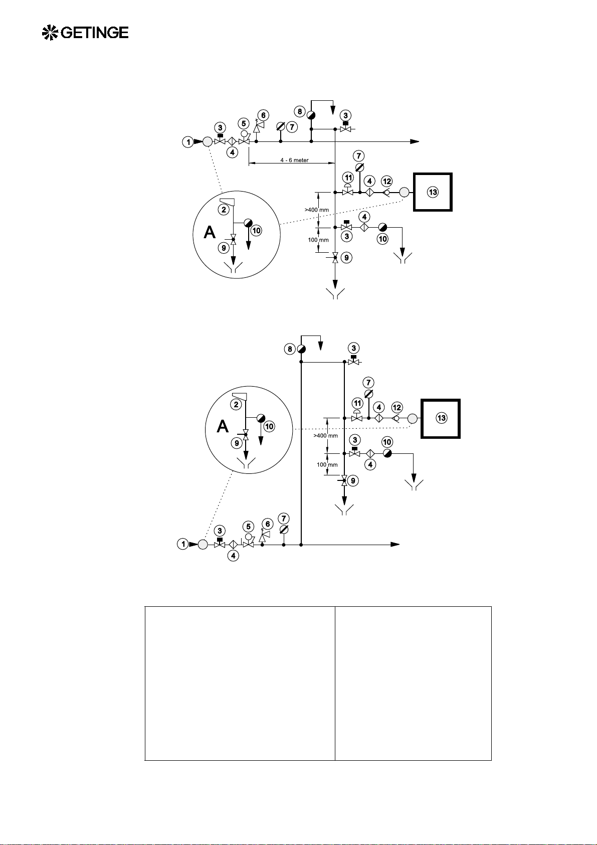
An arrangement as shown below normally satisfies the requirements for
dewateri ng, filtr ation and m onitoring faciliti es when su pplying a
sterilizer with steam from a main steam supply line.
Feed line in the ceiling (bilder skall ändras 12 t.h. om 4)
22
Supply line in floor or in the storey below (ändr)
1 High-pressure line 8 Vent
2 Labyrinth diverter / separator 9 Ball valve
3 Shut-off valve 10 Ste am trap
4 Filter 11
Remote- controlle d valve
5 Reducing valve 12 Check valve
6 Safety valve 13 Sterilizer
7 Pressure gauge

Compressed air quality
Instrume nt air
To ensure long life and reliable operation, the pneumatic components of
the equipment must be connected to a compressed air network that
supplies dry air with a low content of particles and oil.
Modern compressed air components are lubricated for life, so there is
no need for oil to be added to the instrument air. The air must obviously
not contain any solvents or abrasive or corrosive foreign substances that
may damage the pneumatic components.
According to international standards, air quality is divided into
classes.
ISO 8573-1 quality classes
Quality
class
1 0,1
2 1
3 5
4 15
5 40
Content of contaminants
Size and max conc.
µm
(µInch)
(4)
(39)
(197)
(591)
(1600)
mg/m3
(ppm)
0,1
(84)
1
(838)
5
(4190)
8
(6704)
10
(8380)
Dewpoint Oil
content
°C
(°F)
-70
(-94)
-40
(-40)
-20
(-4)
+3
(+37)
+7
(+45)
mg/m3
(4190)
(20950)
(ppm)
0,01
(8,4)
0,1
(84)
1,0
(838)
5,0
25
6 - - +10
(+50)
Where the equipment is connected to a common supply of process air
and instrument air, the levels recommended below may be unacceptable
for process air from a hygienic point of view.
Getinge recommends instrument air in the following classes:
-
• Contaminants content Class 3 or better.
• Dew point Class 4 or better.
23

• Oil content Class 3 or better.
Air connection
Instrumen t air only
Some equipment in its basic version has only instrument air. Refer to
the practica l arrangement s below. Any non-r eturn valves, filters, etc.
are supplied by the purchaser, unless the contract states otherwise.
Common supply
If the user’s r equirements for air quality and the compressed air network
can meet the peak loading of the equipment without the pressure
dropping below 6 bar(g) / 600 kPa(g) / 85 psig, process air and
instrument air can be connected to the same compressed air network. A
check valve and sterile air filter, if required, should be supplied by the
customer unless other wise stat ed in the contract . See “T echnical data”
for details of peak consumption, etc.
Separate supply
Some equipment with a high peak process air loading is intended to be
supplied separately with process air and instrument air. The equipment
may not operate properly and may be unsafe if the pressure in the
instrument air supply falls because of high process air consumption.
Any check valves, filters, etc. must be supplied by the customer unless
the contract states otherwise. See “Technical data” for details of peak
consumption, pressure, etc.
Practical arrangements
Connect the air connections of the equipment via a shutoff valve to a
compressed air network with a pressure of at least 6 bar(g) / 600 kPa(g)
/ 85 psig and no more than 8 bar(g) / 800 kPa(g) / 115 psig. See also the
24
document “Technical data”. Where information is contradictory,
“Technical data” always takes precedence.
1
4
Drain
2
3
5
1 Main supply line 2 Shut-off valve
3 Filter 4 Pressure gauge
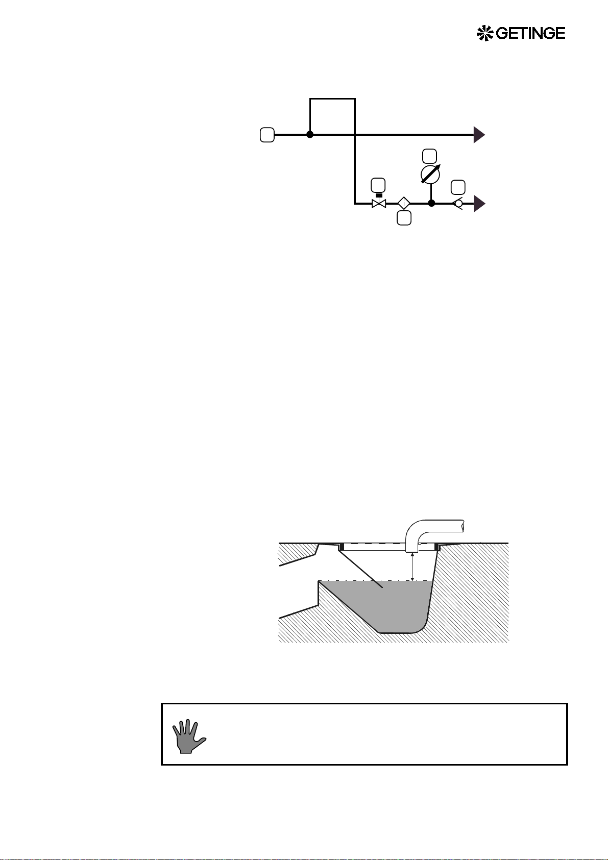
Waste pipes coming from different parts of the equipment must not be
combin ed. The y must be piped se parate ly to the floor dra in with out
restriction or back-pressure.
Comply with local regulations relating to waste water (addition of
formalin, temperatur e re str ic tions, etc. ).
• Run the drain pipe(s) with a f all towards the floor drain, where it/the y
must terminate at a distance of at least two pipe diameters above the
highest water level of the water trap, but at least 20 mm (1”) above
the water level (dimension A). Pipes less than 1.5 m (5 ft) long
require only a minimal fall.
A
• Design the waste pipes for short duration temperatures of about
100oC (212°F)..
Plastic waste pipes shou ld be avoid ed, as a los s of cooling
medium may result in the outlet being exposed to waste
water at 100°C (212°F) for a long time.
25

• The capacity of the waste water system must comply with current
regulations. The technical data of the equipment states starting
values for the calculation of standard flow in hospital and industrial
environments. These calculations must be made in accordance with
national regulations. Normally, after calculation of the design flow
rate, the system capacity must be increased by an additional 50 %.
• The size and number of floor drains must match the size and number
of the connections on the equipment; see Technical data. The floor
drain opening should be at least 200 mm (8”).
Outlet from safety valve
The equipment and/or its supply lines are fitted with one or more safety
valves. Safety valves on equipment with a small opening are fitted with
outlet pipes which carry the blown-off steam or air to a safe position in
the service area.
Safety valve outlets 50 mm (2”) and large r are normally not fitt ed with
outlet pipes at the factory.
Ventilation
We always recommend, where circumstances allow, that the oulet
pipes are re-routed so they they end at a safe place outside the building.
In some countries this is a requirement of the pressure vessel authority.
The reason for this is that, in most cases, it is safer to arrange for the
steam/air to be discharged out side t he ser v ice ar ea because of the large
volume ejected. If this cannot be done, the safety valve must be fitted
with a pipe to carry the steam/air to a safe place. The responsible
authority must approve the choice of outlet location.
Pipework connected to the safety valve:
• must have at least the same size of opening as the safety valve
• must NOT contain shut-off valves or other throttling devices
• must be designed to prevent the formation of water pockets or, if this
is not possible, must be fitted with drain pipes to carry away trapped
water
26
All types of equipment
On the bas is of the va lues for h eat dissipa tion given i n the tec hnical
data, the ambient temperature around the equipment mus t be r egulated
to 15 to 35oC (60 to 95°F) by means of a suitable ventilation system. If
possible, relative humidity should not exceed 85 %.
These requirements apply not only to the service area of the equipment
but also to the operator areas.
All sterilizers
Bear in mind the heat contribution of the load when unloading and when
storing after the process.
The load contributes a significant amount of heat to the
operator area when th e loa d is un load ed on comp letion of
the process. This heat emission is not stated in the
technical specification.
Sterilizers with a vertically-operating door:
Each sterilizer door is fitted with a ventilation stub, which must be
connected to the ventilation system. This provides an efficient barrier to
prevent excessive surplus moisture a nd heat finding their way into the
operator area.
Inspectio n by auth o rities
The user of the equipment must, upon installation of the unit, inform the
approp riate authoritie s that this ha s been done a nd also comply with
local restrictions governing the connection of water, drainage and ventilation. There are often local restrictions on connection to the drinkingwater mains, on how wastewater is to be treated and how ventilation is
to be arranged. This is particularly importa nt when installi ng steril izer s
for formalin sterilization or ethylene oxide sterilization as limit values
for emissions may have to be complied with.
The owner of the equipment must find out whether a pressure vessel authority inspection must be carried out prior
to use.
Response for pressure vessel and safety valves
Pressur e vessels s ubjected to cycl ic loads mus t accordi ng to pressure
vessel regulations be inspected periodically.
The end-user is responsable to arrange inspections of pressure vessels
and checks of safety valves in accordance with requirements f rom notified bodies in each country.
All equipment with safety valves: If the equipment is provided with
one or more safety valves, a description of a check is to be found in the
section Check of safety valve in the chapter GENERAL ADVICE.
All equipment with bursting disc: A description for assembly of
bursting discs is to be found at Assembly of bursting disc in chapter
COMPONENS.
27

Pressure vessel with door(s): If the equipment is provided with pressure vessel doors, a description of a safety check is to be found in the
DOOR chapter.
Only for equipment according to the European pressure vessel
directive: T he first inspection must be carried out at the latest upon a
number of cycles given by the manufacturer on the pressure vessel EEC
declaration of conformity. Further inspections is stated by the notified
body, normally at the first inspection.
Functional check-up prior to use
• This function check must be carried out by a s killed te chnic ian. See
chapter FUNCTIONAL CHECK for further information.
• For sterilizers that are to be validated under European Standards, the
function check must be based on instructions according to EN554.
The user should set up a routine for continuous tests of the equipment.
28

FUNCTION CHECK
Before use
Read all the documentation and check that all supply
media are correctly connected to the connection points.
• Check that the guidelines of the installation instructions about the
connection of supply media are followed: electric power, water,
compressed air , steam, etc.
• Check also that the guidelines for waste and ventilation have been
met.
• Check that the operating instructions are displayed at the unit.
• Carry out any customisations of the unit (where applicable). See the
section headed “Functions which can be programmed by the user” in
the chapter on ADVICE AND INSTRUCTIONS.
• Check that all the connecting screws belonging to electric cables are
sufficiently tightened. Pay particular attention to power wiring.
• Open the valves for all supply media.
• Check that the water tank level is about 13 mm (1/2”) below the spill
way. Adjust if necessary on the float valve.
• Check that the feed water enters at least 20 mm above the overflow
level.
• When the feedwater tank is full of water, check the direction of
rotation of the vacuum pump by briefly pressing the contactor. The
direction of rotation of the pump must agree with the arrow on the
pump housing. To reverse the direction of rotation, follow the
instructions under Electrical in the chapter INSTALLATION.
• If the vacuum pump does not draw sealing water immediately when
it starts, fill the feedwater tank to the brim by closing off the
overflow and holding down the float. It may also be necessary to
briefly open the pump t hrottle va lve fully, to restore it to the correct
position when the pump gas started to draw water.
Do not let the pump run dry for more than a few seconds.
29

• If the vacuum pump has jammed, pull off the pump impeller
according to the instructions in the COMPONENTS chapter of this
manual.
• Perform all safety checks as described in the GENERAL ADVICE
and The Door chapters.
• Check and, if necessary, adjust the supply of sealing water and leak
air to the vacuum pump. See under the heading “ECO-water
conservation system” in the MAINTENANCE chapter for
adjustment of the sealing water, and under “Vacuum pump” in the
COMPONENTS chapter for adjustment of the leak air.
• Check the fans for correct direction of rotation. When seen from
inside the chamber, they should rotate anti-clockwise. To reverse the
direction of rotation, follow the instructions under Electrical in the
chapter INSTALLATION.
• Check that condensate drips down into the collecting cups at the fan
seals when the sterilizer is running. The rate should be a at least five
drops per second (200 ml/minute).
• Check that the fan seal does not leak condensate through the
overflow pipe.
• Do a leakage check on the installation and the sterilizer. Covered-in
equipment and cabinet models must be checked with the cladding
plates removed.
• Run all processes while checking pressure, temperatur e, times and
the operation of the indicator lamps. Set points will be found in the
phase list. File the test run printouts.
Note that the basic version of some equipment, and apparatus
connected to higher-level systems, may not have special provision
for process printout.
30

MAINTENANCE
To be do ne by trained technic ians only
ESD (Electrostatic discharge)
ESD damage in installation and servicing may destroy the
electronic equipment. Read the instructions in the ESD
section in the INSTALLATION chapter BEFORE starting
work.
Overview of safety d evices
Claddi ng and front panels must pr event access to the parts
of the installation that are normally accessible only to
trained personnel.
General access to an installation supplied without
cladding, which should normally only be maintained by
trained personnel must be prevented. A convenient way of
preventing ac cess is t o in sta ll th e e qu ipment in a lo ckab le
area.
The cladding panels of the unit, or if none are fitted, the room in which
the unit is installed, must ensure that only authorised and specially
trained personnel can have access to the internal parts of the installation.
Safety components
Every unit is equipped with a number of components with the specific
purpose of ensuring the safety of personnel. These items are marked
with the a warning triangle below in the following documents:
• electrical diagrams
• pipework diagrams
• spare parts lists
31

These comp onents have und ergone sp ecial tests befor e being
accepted as safety components. For this reason, they must not be
replaced with components of any make or design that has not been
approved by GETINGE AB. It is of the highest importance that the
operational reliability of thes e components is continuously upheld
during the entire service life of the installation. The signs [tecknen??]
are used not only to indic ate important components, but als o to draw
attention to other safety factors that call for special attention, such as
dimensions, tolerances, materials, etc .
After commissioning
When the sterilizer has been in service for one month, deposits and
particles from new pipes will have collected in filters and sensitive
components. If these deposits are not dealt with they will cause
malfunctions, leakage and reduced performance.
• Clean all dirt filters and restrictors.
• Clean all steam traps. Remove deposits on their seats and floats.
• Check that the pipework of the installation and unit is leaktight.
• Check that all the electrical connection screws on power, earth and
neutral cables are tight.
• Clean the plastic strainer in the float valve inlet.
• Perform a leaktightness test by running the Leakage test process. See
Leakage test in the OPERATOR MANUAL under The process.
After a long idle period
After the sterilizer has been idle for a long time, it is advisable to carry
out the actions below. A long idle perio d may be a shutdown or a
holiday.
During the idle period
• If possible, the unit should be started and operated once a week.
On starting after the idle period:
• Run an approved leakage test.
Maintenance plan
Replacing the air-in filter
Depending on the size of the sterilizer, the air-i n filter mus t be changed,
after a certain number of processes as stated below, or when pressure
32
equalisation takes too long.
In any event, the filter must be changed at least once a year.
Replacing the sterile filter
Depending on use, number and size, the filter should be replaced, in the
event of a breakdown or according to local regulations, but in any event
at least once a year.
The integrity of the filter should be checked in accordance with local
regulations or every week in continuous operation.
The filter units should be replaced more often if the
environment is damp or dusty.
HS 6606 300 cycles
HS 6610 275 cycles
HS 6613 250 cycles
HS 6617 200 cycles
General gui delin es fo r peri od ic main te na nc e
In many cases, maintenance specified under weekly and monthly can be
done by an authorized user trained in perfor ming the stated tas ks. The
slightly more demanding maintenance tasks under quart erly, six-
monthly, etc. must be done by trained technical maintenance personnel.
Local and national safety regulations must always be followed.
Once a week
Check the air-in filter for a tight and rigid attachment.
•
Monthly
•
Check that the door closing motion can be stopped by gently
pushing, the squeeze protection plate in the door anti-motion
direction.
• Check the operation of printer pens, ink cartridges and/or ribbons,
for example by checking the graphical printout. Replace if
necessary.
33

Quarterly
Every six months
Carry out the maintenance under “Monthly”.
•
• Check the door seal. If necessary, lubricate or replace the seal. See
the section on DOOR. Note that special operating conditions and/or
media quality may require shorter or longer intervals.
• Perform a leaktightness test by running the Leakage test process. See
Leakage test in the OPERATOR MANUAL.
Perform the maintenance operations as described under "Every
•
month" up to and including "Every three months".
• Clean all dirt filters and restrictors.
• Clean all steam traps. Remove deposits on their seats and floats.
• Check that the pipework of the installation and unit is leaktight. Seal
all leaks. Replace any leaking gaskets.
• Check that all the electrical connection screws on power, earth and
neutral cables are tight.
• Clean the plastic strainer in the float valve inlet.
• Perform the following maintenance operations, which are described
in more detail under DOOR.
· Check the door action.
· C heck the door position vertically, laterally and backward/
forward.
· Checking the operation of door seal and seal groove valves.
· Lubricate or replace the door seal if necessary.
· Perform safety checks as described in “Door safety devices”.
· Perform safety checks as described in “Interlocking the start
function”.
· Safety checks as described in “Blocking of chamber media
supply”.
· Safety checks as described in “Safety blocking of door opening”.
• Check the lead seals on all safety valves.
34

• If the seal is not intact, the valve must be replaced. Alternatively, an
authorized person from the pressure vessel authority can be called to
re-inspect and re-seal the valve.
If the seal of a safety valve has been broken, the
opening pressure may have been changed.
Units with broken safety valve-seals must not be used.
• Check that none of the safety valves is leaking water or steam.
• Clean the flow restricters and adjust the flow of vacuum pump
sealing water if necessary, as described under “Maintenance” in the
“ECO water saving system” section.
• Print out the list of the twenty mos t recent faults (see the CONTRO L
UNIT chapter) and assess whether these indicate faults in
components or incorrect settings.
• Check the operation of the operator panel display, any LEDs and
printer, if any. See the CONTROL UNIT chapter.
Yearly
•
Perform the maintenance operations described under “Monthly” up
to and including “Six monthly”.
• Temperature sensors and pressure sensors connected to the control
system must be checked against an independent system with
documented accuracy, traceable to a national standard. Note that the
measurement error of the reference instrument must not exceed onethird of the measurement inaccuracy to be achieved. National
standards and local regulations must be complied with.
Temperature check: We recommend doing the check in ice water
at 0 °C (32 °F) and in an oil bath at process temperature, eg 121 °C
(250 °F). It is very important to allow the sensors to stabilise in the
baths before doing the check. An ice bath must be filled with crushed
ice and be properly stirred.
The temperature measuring error must not exceed 0.5 °C (0.9 °F).
Calibration of temperature sensors, see CONTROL UNIT.
Pressure check : A reference instrument for pressure checking is
usually combined with equipment for raising and lowering the
pressure. If this is not the case, the check can often be done by
connecting the reference instrument directly to the unit and using the
built-in features to alter the pressure. Note that the pressure
measuring system of the unit can detect pressure changes within ± 1
mbar / ±0.1 kPa / ±0.0145 psi and that the permitted measurement
error below refers to absolute levels for the entire range.
35

The pressure measurement error must not exceed ±8 mbar / ±0.8 kPa
/ ±0.115 psi within a range 0-1 bar(a) / 0-100 kPa(a) / 0-14.5 psia.
At pressures above 1 bar(a) / 100 kPa(a) / 14.5 psia, the difference
must not be greater than 0.01 x P(a). Calibration of pressure sensors,
see CONTROL UNIT.
If the pressure sensor of the unit is removed, the gasket
must be replaced with a genuine Getinge spare part.
• Check and adjust the water level in the feedwater tank so that it is
about 12 mm below the overflow.
• Check that the feedwater inlet pipe discharges at least 20 mm above
the overflow outlet.
• Check and adjust the amount of sealwater to the vacuum pump and
where applicable its cavitation protection, according to the
instructions under “Vacuum pump...” in the COMPONENTS
chapter.
• Run all processes while checking pressure, temperatur e, times and
the operation of the indicator lamps. File the relevant process
documentation such as recorders charts, process printouts or log files
from the test runs.
Additional maintenance operations, every second year
Perform the following operations, as described in the “Heat
•
exchangers” section of the COMPONENTS chapter.
· If the water is harder than 4 dH (70 ppm), clean all plate-type heat
exchangers.
· Pressure-test al l the heat exchanger s.
• Replace the humidity protection device in the control cabinet. Write
the replacement date on a label and attach the label beside the
humidity protection device.
Cycle counter
The PACS 3000 control system is fitted with a cycle counter. The cycle
counter is p rinted o ut on each p rocess log with Sup ervisor or an A4
printer connected to PACS 3000. On cold-start or replacement of CPU,
this cycle counter will be reset to zero. The cycle counter can only be
adjusted or read off using GETINGE CS 1000.
36

The ECO water-saving system
Patent pending PCT/SE94/00998
The autoclave is fitted with the ECO (economy-ecology) water-saving
system. This means that the wat er system s of the autocl ave are divided
up into two separate pipe networks. One system contains water that has
come into direct or indirect contact with the it ems, and has consequently
been contaminated. The other system contains water that has been used
for cooling in such a way th at it is not contaminat ed and can therefor e
be used as process water.
The contaminated water is mainly us ed as sealing water to the vacuum
pump and is circulated in a system where it is cooled and diluted with
approximately 1/6 fresh water from a water tank with air disconnection
to increase pump capacity.
ECO-system reduces the water requirement by approximately 40 % if
the pure process water is not re-used and approximately 75 % if this is
re-used.
E
4
3
A
1
2
A Cold water
B Clean process water inlet
C Clean process water outlet
D Contaminated process water outlet
4
4
B
C
D
E Ventilation
37

Recovery of cooling water
Connections A and B are normally linked, but if the water in the cooling
water circuit is to be re-used as process water, th en A and B will be
separated. Water via connection A will be used exclusively for sealing
water for the vacuum pump and, in certain cases, also as feed water for
the steam generator.
Connections B and C will have been connected on installation to the
special cooling water circuit for re-use, for which the following
requirements apply.
• Incoming water pressure (B) must not be higher than 10 bar(e).
• The pressure in the incoming supply main (B) must be at least 3 bar
higher than in the return main (C).
• The temperature in the incoming main should not be higher than 20
°C, and the water hardness should not exceed 4 °dH (0.7 mmol/l).
Maintenance
Restrictions
Fixed restrictions 1 and 2 and ball valve 3 must be cleaned at least every
six months. Note or preferably mark the setting of the ball valve before
it is removed.
Take care to set the ball valve opening angle after reassembly as it was
prior to disassembly.
Settings and inspection
• Adjustment of settings/inspection can most suitably be performed
during a process incorporating post-vacuum, as the vacuum pump is
then working under stable pressure conditions.
· 5. 5 cm height in the tank is equivalent to approximately 1 litre.
· C a refully ke ep ing the float valve in its closed position, use a
stopwatch to measure the time for the water level to drop by an
amount equivalent to one litre.
Note: The water level must drop in the tank a s a whole. If the tank
is divided, it may be necessary to remove the divider in order to
ensure this.
· Calculate the flow capacity through the restriction 1 and 2 using
the formula given below. The capacity must be within the range
of the value shown above.
(measured volume in litres / measured time in seconds) x 60 =
litres/min.
· If necessary, adjust ball valve 3 if the capacity in the fixed
restriction is not within the specified range.
Reducing the flow through the ball valve automatically increases
the capacity through restriction 1, while increasing the flow
through the valve produces an opposite effect.
38
· Return the equipment to its normal operating state.

Heat exchangers
The plate heat exchangers must be cleaned at least once every two
years. Clogging depends very much on the water quality, and
particularly on the water hardness. The part of the system that is most
inclined to clog is the final heat exchanger before outlet C. Clogging
causes a reduction in cooling capacity and longer process times.
When the h eat exchanger s are cleaned , they should als o be pressur etested in order to check that no cracking has occurred.
Cleaning, pressure testing and capacity testing are described in the
"Heat exchangers" section of the COMPONENTS chapter.
Recycling of cooling water
Connections 1) and 2) are normally connected together, but when the
water in the cooling circuit is to be recycled, 1) and 2) are separated.
Connection 1) is then used exclusively for sealing liquid for the vacuum
pump.
2) and 3) are connected during installation to the special cooling water
circuit for recycling. This is subject to the requirements of the document
“Technical Data” and the INSTALLATION chapter.
Warranty
Service
Spare parts
Warranty conditions and warranty period are described in the
commercial documentation. See the order confirmation that governs the
terms of delivery for this unit.
Contact your local GETINGE representative
or
GETINGE Service Team
International dept.
Phone: +46 35-15 56 36
Fax: +46 35-583 08
Contact your local GETINGE representative
or
GETINGE
Spare parts dept.
Phone: +46 35-15 56 37
Fax: +46 35-15 56 60
39

40

ADVICE AND INSTRUCTIONS
Manual interventions in the process
When faults occur during a process because of interruptions in the
supply of media or compone nt faults, the process may, after an alarm
has been triggered, get stuck in a phase from which the control
equipment cannot proceed.
Various options are then open to the user. Options that do not involve
a hazard to the user are described in the “Alarms” section of the
OPERATOR MANUAL. If the operator’s options for action are not
possible or do not solve the problem, a trained technician must be called
to advance the program manually.
With the stepping option, a technician can under certain
circumstan ces m anu ally b ypas s bu ilt- in saf ety co nd itio ns.
Manual stepping with keyswitch
On manual stepping of a program with the button or the “STEP”
button after the keyswitch has been set to Stepping/Authorized us er, all
parameters are controlled by the automatic control equipment, so that
hazardous situations cannot normally occ ur. With manual control, the
program is stepped from one process phase to another without
temperature, time or pressure conditions being met.
For safety reasons, the ability to step past critical process conditions
is blocked. This applies to certain pres sure, temperature and leve l
conditions, except where there is a fault in an anal og sensor. Stepping
should be while the unit is still in the alarm phase.
When using this method, the blocks that prevent
hazardous situations from arising are removed. The
technician himself has to decide which operations are
permitted.
The above method may only be used by technicians who
are thorou ghl y familiar with the proc ess, th e proper tie s of
the goods and the functioning of th e individual
components.
41

Faulty analog sensor
If an analog pressure sensor or temperature senso r becomes faulty
during a pro cess, the process st ops. The ty pe of fault does not all ow
restarting of the process, since the sensor fault persists after
acknowledgement, even if it is not indicated again. Another
consequence of a faulty analog sensor is that no pressure or temperature
controller becomes operative. This in turn means that neither
temperature, pressure nor ramped temperature changes can be
controlled.
With a pressure sensor fault, the operator must also step past the
pressure conditions on post-vacuum, evacuation, emptying, selfcooling and pressure equalisation. With a temper atur e s ensor fault, the
operator must step past the corresponding temperature conditions.
Sensor fault, independent system
In case the process is stopped in a cooling- or door opening phase, due
to failure of the independent sensors, the safety system can be by-passed
by manual operation of the safety relays.
See the electric wiring diagram.
Pressure sensor fault
Temperature sensor fault
Manual control by manually actuating the control
valves
The above method can be used to check the operation of individual
components, for troubleshooting and with system faults that keep the
process in the same phase.
When operating from menus on the operator panel or via a program
tool, there ar e no software interlocks to prevent haza rdous situations
arising. See the CONTROL SYST EM chapter for precise info rmation
about which menus are used at each interface.
When control valve s are operated directly t here are no interlocks at
all. We advise against this form of control.
42
Note that when operating via the operator panel or programming tool,
it is extremely important that all output s are reset to auto mode when the
work is complete. If this is not done, the safety and operation of the unit
will be at risk during the remainder of the process.

Normally the operator is informed at the start of the next process if an
output is set to manual mode. Despite this, the status must always be
reset to auto mode immediately on completion of work.
When using this method, the blocks that prevent
hazardous situations from arising are removed. The
technician himself has to decide which operations are
permitted.
External safety interlock fault
The sterilizer is equipped with an aut omatic monitoring system for
those external components that serve as safety interlocks independently
of the control system.
If the external components changed the ir position, or got stuck a nd ar e
constantly indicating “safe position”, this would not normally have
been noticed in service. It would only have been discovered when it was
too late and the control system ha also failed, ie when the external
components were needed for safety purposes.
The purpose of the monitoring system is to ensure the operation of both
the safety systems that allow media, among other things, to be admitted
to the chamber or the door to be opened.
Monitoring is done by a system of relays which is in contact with the
external components and the control s ystem. At certain predeter mined
places before and during the process, t he control system checks by
means of the relay monitoring that the respective external component
has opened or closed its contacts as expected.
If the relay information does not agree with the contr ol system’s own
information, the control system stores the discrepancy until the process
has ended.
After the process, an alarm is activated and a message indicated what
type of interlocking is present (see also “Fault codes” in the operation
chapter of the OPERATION manual).
The alarm cannot be reset in the normal way, and as long as the alarm
is activated, a new process cannot be started.
INTERLOCK FAULTS
1. Shut off the audible signal by pressing the button or the
[ALARM OK] button.
2. Rectify the faulty component.
3. Activate the stepping key and reset the alarm with the button
or the [ALARM OK] button.
4. Set up the component and do a safety check. The procedure is
described in the DOOR chapter.
43

5. Check that interlock faults have not been activated after completion
of a process.
Backup battery fault
If there is a f ault in the control sy stem backup battery, an al arm is
triggered when the current process has ended and the control system has
returned to the standby phase. In this mode, no parameters or program
sequences have been lost. Data is only lost if the power to the control
system is turned off with the main switch or if there is a power failure.
Before shutting down:
1. Save the program in the flash memory or in a file; see also the
CONTROL SYSTEM chapter.
2. Make sure that the program has been saved, so that it can be
reloaded.
3. Only turn off the operating current when you quite certain that the
program has been saved.
Replace battery
The battery cannot be replaced. Instead, order an replacement CPU
board if a new battery is needed.
WARNING!
Lithium battery. Explosion hazard.
We advise against any attempt to replace the battery!
If a new battery is needed, order a replacement card.
Never replace the battery with a type other than that
supplied.
When operating voltage is lost:
If the backup battery voltage is low at the same time as a power failure
occurs during a process, all software is lost.
The control system can no longer check the process, and the unit must
be brought to a safe mode by manual control. See the description of the
menus for testing dig ital outputs in the chapter CONTR OL UNIT
PACS3000.
44
When using this method, the blocks that prevent
hazardous situations from arising are removed. The
technician himself has to decide which operations are
permitted.

The above method may only be used by technicians who
are thorou ghl y familiar with the proc ess, th e proper tie s of
the load an d t he f unctio nin g o f t he indi vidual com po nents.
Note: If the control unit PROM is to be used to restore the
software by a “cold start”, w hen th e unit has bee n broug ht
to a safe mode, all changes made and calibrations done
since delivery are deleted.
Restoring software from E-PROM (cold start)
Cold start may only be done with the unit in a safe mode
and by a technician who is thoroughly familiar with the
process.
Read the warning below and then the cold-starting
instructions in the chapter CONTROL UNIT.
Warning
When programs are loaded from a PC or on cold starting from a PROM,
the system goes to standby phase; this means that risky situations may
occur.
Before loading/cold start, the unit must first be brought to the standby
phase or brought manually to a non-hazardous phase where the vessel
contains no water and/or condensate, is depressurised and any liquid
loads have cooled. See also the separate instructions for manual
handling in this chapter.
A cold start from the PROM means th at old values w ill appear for
settings that have been changed in the RAM.
In a similar way saved, old values are loaded from PC. This makes it
necessary to update any changes and calibration values. Calibration
values from the latest calibration for analog sensors must also be
entered.
45

Manual door opening
The following important steps must be taken into
consideration before a door is opened after manual
intervention.
• Identify the valve that is to be operated, to be s ure that it really is the
proper valve.
• Manually open a drain valve, to drain the chamber of liquids.
• Depressurise the chamber by opening the drain valve.
• If the load consists of liquid, the door must not be opened until the
temperature of the liquid is well below its boiling point.
Power failure alarm with door open
If a sterilizer door is partly or wholly open, an alarm will be generated
for safety reasons after a power failure. The doors must therefore always
be closed when the control power supply is turned off.
User-programmable functions
Barri n g co de s
In the control system there are four different types of code, permitting
four different types of action. The purpose of these codes is to prevent
people who do not have sufficient knowledge or authority from
accessin g, intentiona lly or acciden tally, actio ns whose cons equences
they cannot foresee.
It is important that these codes are communicated only to people who
need them in their work and who have the necessary expertise /
authority.
1. Operator code
This code prevent the starting of programs that are intended as test
programs, emergency programs or programs for the sterilization of
liquids. It is a common feature of these programs that they need not be
validated for routine sterilization.
On some autoclaves the authorization code also prevents the door
being opened after an incorrect process.
46

2. Parameter code
This code prevents uninte ntional altera tion of adjusta ble parameters.
Adjustable parameters and the ranges within which they can be set are
evident from the program combination. The program combination also
shows which values are stored in the control system EPROM on
delivery.
3. Team leader code
The code prevents a change to the control system ca lendar be ing made
unintentionally. The team leader is also aut hori sed to cr eate new codes
at operator and parameter level and to print out program documentation.
4. Service code
This code prevents access to menus offering settings and tests that
require an authorized technician.
5. Programming code
This code prevents acc ess to the m enus that can be used to change t he
sequence program.
This code is used only in exceptional cases by users, since this level of
authorizatio n calls for very detaile d knowledge of the contr ol system
programming and the design and operation of the autoclave.
6. Calibration code
The code prevents calibration happening unintentionally.
On delivery, the autoclave control system has four different codes.
These are described in a s eparate document in a sealed envelope. The
codes can be changed by the user. A br ief description of the procedur e
for this is included in the sealed document.
Changing the program description parameters
The parameters that are most likely to need changing during
programming at the user’s premises are listed in the programming
combination.
The ability to change parameters in a program combination varies
from o ne appar atus to an other. Some equi pment has a very la rge
number of selectable parameters; other equipment has few or none. The
degree of possible adaptation depends on the user’s requirements and
official demands within the application, and on the level of training of
the operators.
As well as parame ters for ste rilizing temperatu re and ti me it is
sometimes possible to adapt the post-treatment of the processes to
achieve maximum dryness of goods that are difficult to dry, to set the
desired liquid temperature, or to protect the gods from over-rapid
changes of pressure and temperature.
See also the section on setti ng the parame ter values in the CONTROL
SYSTEM chapter. Suitable settings for steam sterili zers with different
types of goods are described in the separate Getinge guide
STER ILIZATIO N W ITH STEAM.
47

Maintenance codes
Time-based or cycle-based intervals can be programmed so that the unit
keeps track of when maintenance is needed. A number of intervals are
already programmed on delivery, in accordance with the
recommendations in the MAINTENANCE chapter. If the DIP switch
for maintenance message is activated, the end of a service interval will
trigger a “MAINTENANCE” message.
Thos function is not enabled on delivery, since not all users have the
CS1000 tool which is needed to reset an active message. The
maintenance menus are updated in the background even if the DIP
switch is disabled, and can be used, for example, when a service
technician with the CS1000 tool happens to be visiting.
See also “Service indicator” in the MAINTENANCE chapter.
Date and tim e
The service code gives access to menus where the date and time can be
changed. See the CONTROL UNIT chapter.
Calibration
Analogue sensors/transducers must be calibrated, for example when
replaced. The calibration menu becomes available with the service
code. See the calibration menus section in the PACS 3000 CONTROL
UNIT chapter
When using an oil bath, note the following points:
A Accuracy must meet the requirements of EN285
B Compounds or condensation in the oil may cause coatings and thus
severely reduced the accuracy of measurement. Change the oil at
regular intervals.
C Use an oil bath with a large capacity, preferably more than five
litres.
D Allow the measuring instrument to stabilize for one to two hours
after the bath has reached the set temperature.
E Allow the oil bath to stabilize for at least 30 minutes after the
sensors are lowered into the bath and the bath has regained its set
temperature.
F Clean the sensors thoroughly to remove the oil after calibration.
48
Note: If the EPROM in the control unit is to be used to
restore the software by means of a cold start, after the
autoclave has been broug ht to a safe state , all changes an d
calibrations perfo rmed afte r delivery will be erased.

Setting the autoclave number
The autoclave number is an identification of a particular autoclave
which is used in communication between operator control panels or
GETINGE programs. The number, which must be in the range 1 - 99,
also serves as an identification on printed listings of process data and
thus makes the lists traceable.
The programming proceeds as follows:
• Go to menu Configuration – Pacs address.
• Enter the autoclave number in accordance with the instructions for
this menu as given in the PACS 3000 CONTROL UNIT chapter.
• Exit from the menu.
Log interval for process data
The log interval can be changed so that more or less measurement data
is printed out. Logging during the sterile phase is controlled by the value
"Short interval", whilst printout of data during the remaining parts of the
process is controlled by the v alue "Long inter val". On deliver y, both
these values are set to 59 min. 59 sec. Usually this setting only gives
printout of data when the sub-process changes.
See also th e "Print er" section in the OPE RATION chapter of th e
INSTRUCTION MANUAL or, if the equipment includes Supervisor,
the "Documentation of the process" section in the PROCESS chapter.
The programming proceeds as follows:
• Go to menu Configuration – Printer log values.
• Set the required long logging interval in accordance with the
instructions for this menu in the PACS 3000 CONTROL UNIT
chapter.
• Exit from the menu.
49

Safety valve check
Raising the pressure and checking the unit
The following pressure testing of safety valve s can be don e on
equipmen t supplied with incomi ng media at a p ressure abo ve the
opening pressure of the safety valve. Checking of safety valves on
equipment with a lower pressure or safety valves combined with a
bursting disk is described below under Testing in a test rig.
Identify the opening pressure of the safety valve by reading off the
pressure on the valve itself. Note that the design pressure of the pressure
vessel may be higher than the opening pressure of the safety valve. The
pipework diagram of the unit may also be useful for identification
purposes.
Wear safety gloves when checking a safety valve.
Escaping steam and water and hot pipe components may
cause burns.
Check the operation of all safety valves as follows.
• Start a process and when it has started, stop it with the emergency
stop.
• Reset the emergency stop and acknowledge any alarms.
• Manually operate the pilot valve of the incoming media valve (air or
steam) to the pressure vessel and observe the pressure rise on the
pressure gauge. Blow-off should begin at “Normal opening
pressure” according to the table below. At full blow-off, the pressure
should never exceed the “Max permitted test pressure” in the table
below.
Any safety valve that does not meet these conditions must be
replaced.
Immediately restore the pilot valve to the service position
if the safety valve does not op en or fo r some oth er reaso n
the pressure tends to exceed “Max permitted test
pressure”.
• Return the pilot valve to its normal operating position and te rminate
the process.
Normal opening pressure Max permitted test pressu re
3.0±0.15 bar(e) 3.3 bar(e)
50

310±16 kPa(e) / 45±2 psig 340 kPa(e) / 50 psig
3.5±0.18 bar(e) 3.85 bar(e)
Rated pressure of valve ±5% Rated pressure of valve +10%
Testing in test rig
Equipment supplied with media at a pressure below the opening
pressure or equipment fitted with a bursting disk in combination with a
safety valve cannot be pressure-tested on the unit.
Take care when removing and pressure-testing safety
valves. Make sure that pressure vessels and pipework
systems are depressurised before removing the valve.
Escaping steam and water and hot pipe components may
cause burns.
Check the operation of all safety valves as follows:
• Remove the valve and pressure-test it in a test rig.
• Identify the opening pressure of the safety valve by reading off the
pressure on the valve itself. Note that the design pressure of the
pressure vessel may be higher than the opening pressure of the safety
valve. The pipework diagram of the unit may also be useful for
identification purposes.
• The opening pressure must never exceed the “Max permitted test
pressure” in the table above.
Any safety valve that does not meet these requirements must be
replaced.
51

52

THE DOOR
General
The opening and closing motion of the door is executed by a pneumatic
cylinder. The door motion speed is controlled by adjustable chokes in
the cylinder admittance pipe. As a safety measure there is a squeeze
protection integrated in the top of the door.
lock activates a limit switch which makes it possible to pressurize the
door seal.
steam or compresse d air) the doors are kept l ocked by the a utomatic
control equipment and the door lock described above. The doors cannot
be opened until the condition ''chamber pressure = zero (±100 mbar)'' is
met, not even if an electrical fault results in an opening command.
When the door is completely closed, it is locked mechanically. This
During a proc ess and in th e event of me dia failure (e lectric power ,
The door closing system is made up of a number of
componen ts. Their interact ion has been carefu lly tested to
give the ne cessary safety in ter ms of damage to equ ipment
and injury to peopl e. Th ese parts m ust not be subje cted to
violence or inc orrect o peration that may alt er th eir origin al
function.
Adjustme nts to doors a nd associa ted eq uipm ent m ay on ly
be made by authorized personnel.
Seal between door and chamber
The seal between the door and chamber is formed by a rubber gasket
which can move in a groove around the opening of the chamber.
The moving door seal is pres sed against the door by steam,
compressed air or an inert gas. The media us ed de pends on the type of
unit. The door seal is released when the pressure medium is evacuated.
Some special types of sterilizer are fitted with double door seals.
Where two door seals are used on a negative pressure sterilizer, only the
outer seal can move.
53

Media to the chamber
Before media can be admitted to the chamber, all the requirements
below must be met:
A Emerg ency stop not activated
B Door(s) cl o se d.
C Door seal pressurized.
D Control system giving a control signal to open the media valves.
Checking the door action
The speed of motion of the door can be changed with the variable
restrictor in the air line to the door cylinder. Changing the closing speed
has an equal effect on the opening speed.
1. Check that the door closes in 10-15 se conds. Adjust the rest rictor if
necessary (see pipework diagram).
2. Check that the motion is even and smooth.
3. Check that the door does not scrape against anything during its
motion. Adjustment advice is given under “Adjusting the door
position”.
Checking and adjusting the door position
Always disconnect the compressed air supply before
removing to door or adjusting its position. This ensures
that the door does not move accidentally.
A. VERTICALLY
This adjustment may be necessary of the 3 mm dimension between the
top edge of the door and the bottom of the chamber is not maintained,
or if the door does not fully cover the seal groove.
54
1. Measure the door adjustment required.
2. Open the front.
3. Raise the door by activating its pilot valve by hand.

4. Insert a prop under the door and lower the door until it rests on the
prop.
Make sure the door is resting securely on the prop.
5. Loosen the support bracket (A) and adjust the door to the
measurement, then tighten the screws.
A
B
B. SIDEWAYS
6. Pressurize the door cylinder, remove the prop and lower the door.
Check its vertical position and re-adjust if necessary.
7. Check that the closed door completely covers the seal groove (the
tolerances on the cylinder stroke are close).
8. Check that the top edge of the door is horizontal. If necessary,
slacken the piston rod guide plate (B) for adjustment and move the
piston rod sideways. Tighten the fixing plate screws.
9. Refit removed parts.
The setting of the door locking mechanism must be
checked after adjustment. See under “Interlocking of the
start function”.
This adjustment may be needed if the lateral clearance of 2-3 mm
between the door and the guides is not maintained.
1. Open the front.
2. Slightly slacken the side guide attachment nuts F.
3. Adjust the lateral position of the door with the screws E to give a
lateral clearance of 2 - 3 mm relative to the guides.
55

4. The door must cover the chamber symmetrically, with the minor
deviations that may be required for the clearance to the cladding
plates.
5. When adjustment is complete, secure the side guides with the nuts
F.
C. IN DEPTH
This adjustment may be necessary if the distance between the door and
the chamber is not correct.
1. The clearance between the door surface and the door seal groove
should be about 2.5 mm.
2. Open the front.
3. Slightly slacken locking screws A and locking nut D.
4. Close the door and insert at each corner a strip of sheet steel 2.5 mm
thick between the door and the seal groove (slacken B if necessary).
5. Adjust B until the metal strips are gripped very lightly.
Important: tighten screws and nuts firmly. These screws
and nuts are an integral part of the pressure vessel.
6. Tighten D and A.
56

7. Remove the metal strips.
The setting of the door locking mechanism must be
checked after adjustment. See under “Interlocking of the
start function”.
Removi ng the door
1. Open the front.
2. Place a block or similar to stop the door about 150 mm from its final
position when lowered.
The door must be properl y supported.
3. Lower the door.
4. Remove the air hose connection at the foot of the piston rod.
5. Remove the two leaf springs that press the door forwards.
6. Remove the safety plate on the top of the door.
The door will fall forward when the safety plate and then
the guides are removed. Take care to avoid being trapped.
57

7. Loosen the eight nuts D and remove the screws C together with the
two guides.
8. Lean the top of the door away from the sterilizer and lift it out. The
door weighs about 75 kg.
58

The door seal
Care
The door seal is that part of the pressure vessel that is most expos ed to
wear and tear. T he composi tion of the m aterial, the design of the seal,
its fitting and care are of extreme importance for reliable operation and
long life of the seal. GETINGE's door seal consists of a special silicone
material, and its physical design is intended to make best use of its
special character isti cs .
Use only genuine GETINGE door seals. Remember that
each seal is an integral part of the pressure vessel.
There are several ne gative factors that adversely af fect the life of the
door seal. By avoiding them as far as possible, the life of the seal can be
considerably extended.
• Avoid leaving the sterilizer switched on in the stand-by mode during
the night. Although the door seal material can withstand continuous
temperatures of more than 200 °C, it slowly degrades where it is in
contact with the seal groove. Leaving the sterilizer continuously
energised will shorten the life of the seal by about 60%.
• If the sterilizer has a steam generator, the generator must be drained
at the prescribed intervals. Any feed water other than de-ionised feed
water will gradually build up a concentration of minerals and other
substances. At high concentrations, several of these substances are
carried over with the steam and precipitated on the seal as weak
acids.
• If the sterilizer is connected to a central steam system, the quality of
the steam is decisive in determining the life of the seal. Chemicals
are often added to the feed water for such purposes as protecting
pipes against corrosion. Undesirable chemical characteristics of the
steam include high hydrazine or carbon dioxide contents.
• Keep the seal lubricating layer intact and the sealing groove clean.
The lubricating layer not only assists the seal in sliding, but is also an
effective barrier against long-term chemical breakdown. See also
under the “Lubrication of the door seal” heading.
Checking the pe rformance of the door seal and packing groove
valves
Perform a leak test, as described in the PROCESS chapter in the
OPERATOR'S MANUAL. If the test runs without disturbances, above
valves are working properly.
• In case the steam valve, for the groove, doesn't open the leak t est will
stop.
59
• If the steam valve for the sealing groove does not close, or if the drain
valve does not open, the door cannot be opened after the test as a
result of friction against the door seal. The same thing will occur if
the seal has hardened or if the absence of its lubricant layer has
caused it to fasten in the sealing groove.
WARNING - Risk of crushing
Be very careful if the door remains fastened to the seal.
When it comes away from th e seal, it will drop down out of
control.
• If the leak test results in a pre s sure rise, this can be due to a number
of effects, one of which is a leaking steam valve to the chamber or a
worn seal. A leak of this type will also make it difficult to maintain
a constant temperature in the chamber.
• If a similar pressure rise occurs particularly during the sterilization
phase of programs with high sterilization temperatures, it indicates
that the door seal is worn out.
Lubrication and replacement of the door seal
The need for lubrication or replacement of the door seal can vary,
depending on the factors mentioned above. This means that the intervals
should be adjusted as indicated by experience.
Preparation
Remove one of the safety plate screws and slide the plate towards the
empty screw hole until the other end comes off. Lift it off carefully.
The door will be pushed forward by the spring in the door
catch when the safe ty plate is re moved. Beware of the risk
of crushing.
Make sure that the door cannot be closed accidentally
while work is in progress by turning off the control power
supply and disconnecting the compressed air supply.
60
If, when the door is in its forward position, it is allowed to move
upwards, the g ap between the sealing gro ove and the door will
immediately decrease from about 16 mm to 2.5 mm. There is nothing to

reduce the force behind this movement, and it could severely crush a
hand etc.
Removal and cleaning
1. Remove the gasket from the groove. Be careful with the seal and the
groove.
2. Carefully clean the seal groove.
· First remove any coatings of hardened lubricant with a very fine
emery cloth (no coarser than 320 grit)
· Then wash the groove with a soap solution and wipe dry with
clean paper.
· Wash again until the paper is clean after wiping.
When relubricating an old seal
1. Clean the seal with alcohol until its surface feels absolutely smooth.
On fitting
2. Inspect the seal where it has been in contact with the seal groove. If
the material has started to perish, the seal should be replaced.
3. Spray the entire seal with a thin coat of anti-friction lacquer.
(ordering. no. 4666695-01)
1. Check that the spring is at place at the bottom of the groove.
Relubricated seal
2. Fit the seal as before. Centre the corners so that they are positioned
exactly as before.
New seal
3. When fitting a new seal, it is extremely important that the excess
length is distributed correctly. It helps to have the assistance of a
second person.
61

4. Press the seal join into the middle of the upper horizontal part of the
groove.
5. Secure the seal in the middle of the straight parts of groove so that
its excess length is equally distributed between the fixing points.
6. Press in the seal between the previous fixing points, dividing the
sections into smaller and smaller parts so that the entire excess
length is equally distributed over the entire length.
7. Work some of the surplus towards the corners so that the seal can
properly fill the width of the groove at the radii.
8. Finally press the entire seal into place so that it is inside the edge of
the groove.
9. Fit the safety plate by moving towards the side in which there is no
screw, pressing it down and engaging it on the side in which the
screw has been left. Tighten the securing screw and check its
performance.
Replacing the door cylinder
1. Close the door by operating its air solenoid valve by hand.
2. Place a prop or similar to stop the door about 150 mm from its end
position when lowered manual.
Beware of the danger of insufficient support
3. Remove the cylinder air hose fitting located on the piston stand. Lift
the door slightly, remove the prop and lower the door as far as it will
go.
62
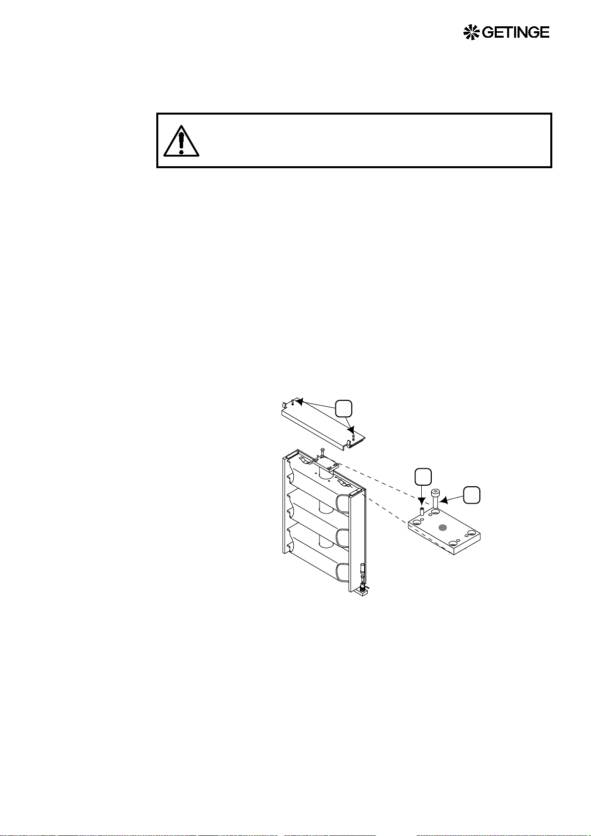
4. Remove one of the safety plate attachment screws and push the
plate towards the empty screw hole until it loosens at the opposite
end. The door will now be pushed forward by the spring.
Beware of the risk of cru shing when the prop and/or safet y
plate is/are removed.
5. By means of a 6 mm Allen key, remove the four cylinder
attachment screws.
6. Prevent the piston from moving out of the cylinder by keeping the
safety valve at its bottom closed (pulled out). Lift away the
cylinder.
7. Attach nipple and hose to the piston of the new cylinder.
8. Fit the cylinder into the door. Prevent as earlier, or with a piece of
string the piston from moving out of the cylinder.
9. Attach it by means of the four Allen screws. With the four adjusting
screws, make the cylinder align with the centre line of the notches
of the stiffening bars.
10. Attach the piston end guide washer in that position which makes the
door move in the most proper way.
A
B
C
Replacing the piston seal
A worn-out piston seal can not be replaced as separate unit but the
whole piston has to be replaced.
First perform ”Replacement of door cylinder”, section 1-7.
1. Fix the cylinder carefully in a vice jaw.
63

2. Remove the cylinder attachment plate.
3. Twist the cylinder end plate until the end of the locking wire
appears in the locking wire hole.
4. Twist the cylinder end plate in that direction which feeds the
locking wire out of the hole. The wire may need help from a tool to
enter the edge of the hole.
5. Pull out the bent end of the locking wire from its driver hole.
6. Remove the cylinder end plate and replace its O-ring in connection
with the replacement of the piston even if it appears to be free from
damage.
7. Push out the piston and fix it in a vice jaw.
8. Protect the piston rod from tool marks with a piece of weak plate
around its lower part, which is stiffened up by an insert piece of
brass, while gripping there, but no where else, with a pipe wrench
or similar tool.
9. Twist the piston rod for regular threading off. If sticky, apply heat
carefully to soften the thread sealing compound. Clean the piston
rod thread with a wire brush.
10. Apply ”Loctite 542" hydraulic sealing compound on the thread and
screw the new piston on to the piston rod.
11. Assemble the cylinder and install it according to the points 8-11
under the head line ”Replacing the door cylinder”.
Door safety arrangements
Squeeze protection
The door mot ion is executed by a pneumatic cyl inder the air inl et of
which is considerably choked. An air exhaust valve having much larger
flow capacity is arranged at the free cylinder end which is directed
upwards. Any obstruction present during door closing exerts pressure
on a pla te runnin g the enti re leng th of the upper edg e of the door at
64

Safety check
which thi s plate ma kes the exha ust valve open, ther eby stopp ing the
upward motion imme diately. This w ill prevent personnel injuries and
material damage.
The safety check shall be performed in the early stage of the doorclosing op eration. This in or der to reduce the risk for injuries due to
squeezing.
1. Check that the air supply pressure is maximum permissible 8 bar.
2. Open the door speed control valve entirely.
3. Close manually the door cylinder exhaust valve and open the inlet
valve to make the door close.
The safety check must be performed as soon as the door
starts to move, in order to minimise any risk of crushing.
Emergency stop
4. Press the centre of the door's safety strip and check that it is free to
move so that the cylinder exhaust valve opens without requiring any
substantial downward pressure. Check at other positions along the
safety strip, to make sure that the required downward pressure is not
excessive anywhere.
5. If the strip is held down, the exhaust from the cylinder must be such
that the door reverses direction and opens.
Pressing the emerge ncy stop push-button imme diately stops the door
motion and switches the control system to the alarm state.
Safety check
1. Open the door and press the emergency stop push-button while the
door is moving. The door must stop and the control system must
generate an alarm. Reset the alarm and the emergency stop pushbutton and repeat the door opening command.
2. Close the door, repeating the above test while the door is closing.
If any of th e above featur es do not wo rk, send im mediat ely
for a trained sterilizer technician for inspection and
adjustment.
65

Blocking the start and opening the door
; ;
; ;
; ;
; ;
; ;
; ;
; ;
; ;
; ;
; ;
; ;
; ;
; ;
To prevent the door from opening by its own weight in case the
pneumatic do or cylinder should become depressu rized, a brace
underneath the door keeps it in closed position. The brace is brought in
stop posi tion under the door b y spring- force 20 sec onds afte r a door
closing command has been given. A limit switch senses the position of
the brace thereby stopping the process from being started and mediums
to be admitted to the chamber before the door is completely closed.
Safety check
1. Check that the air pressure is minimum permissible 6 bar.
2. Admit compressed cylinder air to make the door close.
A
B
3. Check that the measurement ”a” is 3-4 mm.
Adjust the height of the brace when needed.
4. Check that the end of the brace is well within the cylinder
circumference. (”b”= 12-17 mm)
5. Check by hearing that the contact of the limit switch does not
change over until the brace is safely under the pneumatic cylinder.
Beware of the danger of squeezing, while manipulating the
brace.
6. Check that the retaining pin is in place, preventing the limit switch
operating cone from moving on the thread.
7. Operate the brace cylinder air valve repeatedly to check that the
motion of the piston is smooth and free from jerks.
8. Cylinder retraction is restricted in order to reduce the noise level.
The spring return, however, is not restricted. Adjust the retraction if
necessary.
9. Check the screws securing the brace and their condition.
66

Blocking the media supply to the chamber
Media supply to the chamber requires several safety systems to be
intact. The systems are all independent of the control system and cut off
the electric power supply to the media valves.
Limit switches
A limit switch senses that the door is fully closed before the signal is
passed to the media valve.
Adjustment
For safety reasons, the limit switch cannot be adjusted.
Safety check
1. Switch on the operating current with the doors closed and check
that there is voltage at terminal block number 5131.
2. Open the door on the loading side and check that there is no voltage
at terminal number 5131.
3. On double-ended sterilizers, do the same check on the door on the
unloading side, possibly after a process with opening restrictions on
the door.
Emergency stop
An emergency stop button breaks the circuit when pressed.
Safety check
1. Start a process and check that there is voltage at terminal number
5031. Note: This check must be done after the seal has been
pressurised.
2. Press the emergency stop button on the loading side and check that
there is no voltage at terminal 5031. Reset the emergency stop
button and check that there is voltage again at terminal 5031.
3. Finish the process.
4. On a double-ended sterilizer, do the same check with the
emergency stop button on the unloading side.
Door seal steam pressure switch
A pressure switch senses the pressure in the seal groove and cuts off the
electric power supply to the chamber media valves at the sa me time as
the input to the control system is cut off. This results in an alarm when
the pressure falls below the prescribed level.
Normally, double-ended sterilizers have a single pressur e switch for
the seal grooves of both doors, since the seal groov es are supplied in
parallel. This is not the case with double-ended sterilizers with SPF
67

function, nor with ethylene oxide sterilizers. On these, each door has its
own pressure switch.
Identify the co mponents invo lved by referring to th e electrical and
pipework diagrams of the sterilizer. The pressure switch operating
pressure is shown on the pipework diagram.
Setting
1. With the sterilizer in standby mode, switch off the electric power
with the control switch.
2. Shut off the incoming steam and air supplies.
3. Disconnect the connecting pipe and connect a reference instrument
to the door seal pressure switch. Initially the pressure switch must
be kept at atmospheric pressure.
4. Remove the cover from the pressure switch (to access the adjusting
nut).
5. Adjust the pressure switch until the contact closes. For further
information, see under Pressure switch in the COMPONENTS
chapter.
6. Set the reference instrument to the pressure stated on the pipework
diagram, normally 1.7 bar(e) / 170 kPa(e) / 25 psig. If there are
conflicting data, the data on the pipework diagram take precedence.
7. Switch on the power with the control switch.
8. Slowly turn the setting nut on the pressure switch until the LED on
the input of the control unit goes out.
9. Continue with the safety check below, from step 5).
Saf ety ch eck
1. With the sterilizer in standby mode, switch off the electric power
with the control switch.
2. Shut off the incoming steam and air supplies.
3. Disconnect the connecting pipe and connect a reference instrument
to the door seal pressure switch.
4. Switch on the power with the control switch.
5. Close the sterilizer door(s), check that emergency stop buttons have
been reset, and connect a test lamp or similar to terminal 5031.
6. Increase the pressure until the reference instrument shows 3 bar(e)
/ 300 kPa(e) / 45 psig. Check that the test lamp and the control unit
LED are lit.
7. Slowly reduce the pressure with the reference instrument until the
test lamp and the control unit LED go out. The pressure at
changeover should be as stated on the pipework diagram, normally
1.7±0.1 bar(e) / 170±10 kPa(e) / 25±2 psig. If there are conflicting
data, the data on the pipework diagram take precedence.
68
8. Remove the test lamp and the reference instrument.

9. Reconnect the pipe to the pressure switch and refit the pressure
switch cover.
10. Open the incoming steam and air supplies.
Blocki ng the d oor motion and the door seal mediums
The supervisory system is doubled:
1. Through the hardware, with a pressure switch sensing the pressure
in the chamber. The contacts of the pressure switch break the
connection between the control system and the devices that control
the door and door seal outlet, as long as the pressure in the chamber
is higher than atmospheric pressure.
2. Through the s oftware by enabling for the door to be operated only
in the phase “Stand by” i.e. before a process is started and when it
is completed.
Setting the pressu re switch for external blocking
• The setting is done with the s terilizer in stand-by mode. The pr essure
switch is marked PS12 or PS21, depending on the sterilizer model.
The external blocking is at contact interface 1 (PS12/1 or PS21/1, as
appropriate).
• Switch on the operating voltage and check for voltage at terminal
107. If voltage is present, turn the adjusting nut of PS12/1 or PS21/1
clockwise until the voltage at terminal 107 disappears.
• Slowly turn the adjusting nut anticlockwise until the voltage returns
to terminal 107, then turn the nut a further quarter-turn
anticlockwise.
Safety check
• Start a process.
• Check that voltage disappears from terminal 107 before the chamber
pressure reaches 0.2 bar(e).
Safety interlocking of the door opening
The safety interlocks to prevent the door opening a re duplicated, split
between the control system and an independent supervisory system.
The safety criteria of both systems must be fulfilled before the door can
be opened.
69

Independent pressure switch
Adjustment
Adjust the pressure s witc h with the sterilizer in the s tand-by mode. The
pressure switch for chamber pressure is easy to identify on the electrical
circuit diagram sheet for safety interlocks, where the external interlock
is routed through auxiliary relay 1.
1. Turn on the control power supply and check whether terminal
number 5027 is live. If it is, screw in (clockwise) the adjusting nut
for the pressure switch group 1 until the terminal is de-energised.
2. Slowly screw out (anticlockwise) the adjusting nut until terminal
5027 is again energised, and then turn the nut through a further
quarter turn anticlockwise.
Saf ety ch eck
1. Start a process.
2. Check that terminal number 5027 is de-energised before the
chamber pressure has reached 0.2 bar(e).
Independent chamber pres sure switch
Adjustment
Settin g is done w ith the steril izer in standb y mode. Emergenc y stop
buttons must be reset. The chamber pressure swit ch is identifie d on the
pipework diagram and on the safety interlock sheet of the electrical
diagram. To prevent door opening at high pressure, the pressure switch
is wired to break the interlocked signal /5027 before the pressure in the
chamber reaches 0.2 bar(e) / 20 kPa(e) / 3 psig. Getinge recommends
using a reference instrument for pressure measurement.
1. Switch on the control voltage and check whether there is voltage at
terminal 5027. If so, adjust the pressure switch until the voltage at
the terminal disappears. Adjustment is normally done with a nut or
a knob. The adjustment of certain types of electronic pressure
switch may be very different; see also the COMPONENTS chapter.
2. Adjust the pressure switch in the opposite direction until voltage
returns at terminal 5027 and then a bit more, normally about onequarter turn, corresponding to closing at 0.1 bar(e) / 10 kPa(e) / 1.5
psig.
Saf ety ch eck
70
1. Carefully pressurise the pressure switch manually or start a process.
2. Check that voltage disappears from terminal 5027 before the
pressure reaches 0.2 bar(e) / 20 kPa(e) / 3 psig.
3. Reduce the pressure (or wait for the pressure to fall) and check that
the voltage returns to terminal 5027 before the chamber pressure
falls to 0.1 bar(e) / 10 kPa(e) / 1.5 psig.

4. If necessary, repeat the above setting procedure. Always end with a
The control system
Adjustment
The safety interlocking provided by the control system is not adjustable,
since the pressure limits for allowing the door to open are programmed
in the softwar e. Pressur e is measur ed with a dedicated pres sure s ensor
and temperature with dedicated temperature sensors. A faulty or
incorrectly calibrated temperature sensor can threaten the s afety
interlocking.
Safety check
Check the pressure and temperature sensors with a reference
instrume nt. If an incorr ect indicati on is found, rep lace faulty s ensors
and calibrate.
safety check.
71

72

CONTROL UNIT PACS 3000
The letters PACS stand for Programmable Autoclave Control System.
The purpose of the control system is to issue orders and send them to
the executive components of the unit so that a number of pr ocess steps
are performed in accordance wi th a pr edet er mi ned tem plate. The order
signals are worked out by the computer program of the control unit in
conjunction with measurements of actual pa rameter values for the
current program. These are usually times, temperatures and pressures.
Several different pieces of equipment can be connected to the control
unit for programming, monitoring and documenting the processes.
The operator communicates with the control unit via a c ontrol panel
or an ordinary PC. T here are several vers ions of the operator-machine
interface, from the simplest, which consists of two pushbuttons and
eight LEDs to shows that certain statuses have been reached, to the most
advanced, which allow co mplete programming of the control system,
among other things.
All operator panels can be used to monitor the processes, since they
display all the set parameter values as well as actual values on request.
All relevant data associated with a given process, such as batch number,
operator number, date, etc., can be entered by the operator.
Programs, system definitions and process data can be documented by
connecting a printer to the unit. A host computer can also be connected
directly to the CPU of the control system.
If necessary, a measurement and monitoring system which is
completely independent of the control system, ca n be set up by
providing the equipment with a PACS SUPERVISOR. This contains a
separate CPU and its own measur ement and control cards. The
SUPERVISOR performs its measurements by means of separate
tempera ture and press ure sensors alongside those of the control u nit.
The system has links to the control unit CPU and can the refor e use the
shared operator panel, as well as adding the control unit readings to the
process documentation. The SUPERVISOR can also be involved in
independent interlocking of door opening, for example.
The computer contains programs for automatic calibration of the
temper ature and pressu re sensors. Wh ere alternative correction
constants are known, they can be entered manually. The testing
functions include means of activating analog and digital outputs and for
monitoring analog and digital inputs.
The control unit hardware is divided, so that the operator pane ls can
form small separate units that are easy to position at the most suitable
location. CPU, measurement and control boards and the powe r supply
are installed in separate electrical enclosures which are connected to the
operator panels by shielded cables.
73

A number of special terms
STERILIZATION refe rs to the entire series of treatments that make up
a process aimed at achieving the tota l killing of all living organisms.
This applies to sterilizers and usually includes air removal, heat
treatment and a drying phase.
STERILIZING refers to the actual killing part of the process, the heat
treatment.
On the same basis as the two terms above, STERILIZATION TIME
refers to the duration of the entire process from the star t until the objects
can be taken out of the ster ilizer . The PROC ESS TIME i s the sam e as
the sterilization time.
The STERILIZING TIME is only that part of the process for which
the programmed STERILIZING TEMPERATURE exists i n the
chamber.
In this context, PARAMETERS means FACTORS THAT
INFLUENCE THE steriliza tion process. Example s of parameters in the
sterilization process are temperature, pressure, time, humidity, gas
concentration, etc.
PARAMETER VALUES may be permanently set in the program, be
adjusted by the operator, be included in selectable recipes or
downloaded from a higher-level system.
Calcu lat i o n of F0
F00-VALUE is a time which is calculated with the equation
t
T
–
t()k1
------------------ k
F
0
2
10
∫
0
dt×=
t = time in minutes
T(t) =
Load temperature in °C at time t
k1 = Constant within the range 0.0 -150,0 °C. Normally 121,1 °C
k2 = Constant within the range 0.0 -99.9 °C. Normally 10.0 °C
The F0 value is based on the conversion of the instantaneous
temper ature to th e base t emperatu re for ste am steri lizat ion, 121.1 °C.
Through its temperature component, this value provides a measure of
the heat energy supplied.
The F0 value is most commonly used in the pharmac eutical industry,
where the timing of sterilization processes is often based on this value.
Because the sterilizing that takes pl ace during heating-up and cooling
down is partly included in the calculation of the sterilizing time of the
74

goods, there is no need for temperature-sensitive products to be exposed
to a high temperature for longer than is necessary to make them sterile.
75

Operating panel type OP 30
0 0 : 0 3 : 0 0 0 0 : 1 2 : 0 0 1 2 1 . 1
S T E R I L I Z I N G T I M E R E M A I N I N G T I M E S T E R I L I Z I N G T E M P
P 1 W r a p p e d G o o d s
0 2 H e a t i n g
C H A M B E R T E M P
C H A M B E R P R E S S
S E T U P S E L E C T C Y C L E P A R A M E T E R S B A T C H I N F O
1 2 0 . 9
3 . 2 0 0CB A R
E N T E R
0 0 : 1 2 : 2 4
0 0 : 0 1 : 0 7
Indicators and controls
The door(s) is/are closed.
The door(s) is/are closed and locked.
Process running
Process completed without errors
Defective process
Close door
Open door
76

Display
Reset the alarm.
Startup
The display is divided into a number of windows in which information
about the process appears as described below.
1 2
4
5
6
8 9 10
Fields 1 - 3 Process parameters
3
7
11 12
Program number, program name and process time
Field 4
Field 5 Process window
Field 6 Alarm text (white on a red background)
Field 7 Information text (white on a blue background)
Fields 8 - 12 Key texts adapted to each menu
Phase number, phase name and phase time
77

Function keys
Cursor keys
1. Five labels for the function keys appear at the bottom of the
character window. The texts (max two lines of seven characters) are
centred in a window.
2. The key texts always appear in the same place. Example: if the
HEM function is active on any of the display, it always appears in
key position two.
There are five keys for navigation on the panel. These keys (which
always have the same functions) are four arrow keys (up, down, left and
right) to control the cursor and an ENTER key.
On the main process dis play the program keys are used to move
around in the on-screen menu to choose a function.
Using the operator pan el
General
1. The image is normally made up of different displays with different
extra function choices, displays where data appears or displays with
editable fields where data can be entered or changed.
2. The cursor keys are used to scroll through all the selectable fields
on the current display. When you select a field, it is displayed
reversed.
ENTER
78
3. If there are more rows (list entries) than will fit into a single window
(about ten) only the first ten are displayed, and a scrollbar appears
on the right of the display.
4. You can scroll through the entire list with the aid of the arrow keys.
When the cursor reaches the last displayed field of the list and there

are more fields below it, pressing the down key causes the list to
scroll up one row at a time. The same applied when s crolling in the
opposite direction.
5. All selectable list boxes and choices operate as rotating lists. This
means that, if you press the down key when the last choice is
selected (highlighted), the first choice in the list is selected. The
rotating choice list operates regardless of the number of choices
available.
6. The HOME key always uses key position 2 and returns you to the
main menu and logs off the current user.
7. System messages on the panel, such as “System busy” etc appear as
popup menus.
Screen display modes
A display can have up to three modes:
A READ MODE – you can scroll between values
B EDIT MODE – values can be changed
C SAVE MODE – to save edited values
Editi n g fields
• When the display is in read mode, pressing ENTER causes the
display to switch to edit mode and lets you edit the chosen field.
• Arrow keys are used to modify fields.
• When the screen display is in edit mode, pressing ENTER makes the
display change to save mode.
• Arrow keys are used to choose another field.
• When the display is in save mode, pressing ENTER causes the
display to switch to edit mode and lets you edit the chosen field.
• The SAVE key saves value in PACS and puts the display in read
mode.
• Editing numeric fields – The first numeral flashes and the others are
displayed in reverse. The flashing numeral can be increased/
decreased with the up/down arrow keys. Pressing the left/right arrow
keys choose the next numeral to the left/right, and makes it editable
at the same time. If you press right-arrow key at the far right numeral,
the cursor does not move to another numeral. The same applies to the
far left numera l.
When you press ENTER after editing a numeric field, the system
checks automatically that the new value is within the permitted
range.
• Editing option fields – All numerals in the field flash. Pressing the
up/down arrow keys changes the value of the field to the previous/
next value in the list. If the field has the last value in the list, pre ssing
the down key displays the first value. Likewise for the first value in
the list when the up key is pressed.
79

• Editing alphanumeric fields – A keyboard is displayed above the
current screen display. The keyboard is not transparent. A cursor
appears where the field value is located. The field value is empty.
The first key on the keyboard is selected. The arrow keys are used to
access a character. Pressi ng ENT ER places the chosen chara cter in
the field. The arrow keys and the ENTER key are used repeatedly to
place characters in the field. The keyboard supports both upper and
lower case (small and capital) letters. A program key labelled
“SHIFT LOC K ” toggles the display of characters on the keyboard
between upper and lower case. Pressing the OK program key closes
the popup menu and returns you to the previous display. Characters
are entered into the chosen field.
The OK and CANCEL keys
• In READ MODE, the OK key returns you to the previous display
• The CANCEL function always uses key position 1 and is defined as
follows:
· In READ MODE
– return to previous display. No confirmation is needed.
· EDIT MODE, without popup
– returns the original value of the field and changes the d isplay to
SAVE MODE.
EDIT MODE, with popup
– returns the original value of the field, returns the previous
display and changes it to SAVE MODE.
· SAVE MODE
– prompts for “Confirm cancel” (of this function has been
chosen), returns all fields on the display to their original values
and returns the previous display.
• If the option in the panel setting menu for confirmation of save and
cancel is set to Yes, the prompt “CONFIRM SAVE?” appears when
you press SAVE, letting you choose Yes or No. Yes saves the values
on the display and lets you continue. No returns you to the display.
This setting is made in the system menu and is described in the
service manual.
• If the option in the panel setting menu for confirmation of save and
cancel is set to Yes, the prompt “CONFIRM CANCEL ?” appears
when you press CANCEL, letting you choose Yes or No. Yes
restores previous values and lets you continue. No returns you to the
display. This setting is made in the system menu and is described in
the service manual.
80

Operator menu tree
CHOSEN BASIC DISPLAY
MENU
PROCESS VALUES
CURVE DIAGRAM
BAR CHART
EXTRA PRINTOUT
CHOOSE PACS
SYSTEM MENU
APPARATUS INFO
CHOOSE PROGRAM
EDIT VALUES
BATCH DATA MORE...
Description of operator menu tree
Chosen basic display
The control system has three ways of reporting on the process. The
basic setting is defined in the system menu and is described in the
service manual. These three possibilities are described under Settings,
where the display mode can also be temporarily changed.
Menu
Process values
Shows a scrollable list containing the displayable parameters.
Curve diagram
Shows two predefined parameters as growing curves.
Bar chart
Shows two predefined parameters as vertical bars.
Extra printout
This option is only available when the contr ol system is in the standby
phase.
81

When the function has been chosen, a new display with the following
options appears:
1. CANCEL – return to previous menu display
2. HOME – return to basic display
3. NO – return to previous menu display
4. YES – print out the latest process and return to the previous menu
display
Choose PACS
This option only appears if the panel is connected to more than one
PACS or if the sterilizer has a SUPERVISOR.
System menu
Described in the service manual. A password is required for acces s to
this menu.
Apparatus in fo
Displays (among other things) the control system in the form of version
information for the panel and the control system.
The brightness of the display can be increased or reduced with the
number 2 function key (LESS BRIGHT) and the number 3 function key
(BRIGHTER).
Choose a process
Displays a list of availa ble proces ses. If t here are mor e processes than
will fit in a menu display, they are displayed in a scrollable list.
Parameters
Displays a list of parame ters. An “A” be fore the par ameter name means
that the parameter can be adjusted (Adjustable).
Press EDIT to adjust a par ameter. An alphanumeric keyboard now
appears, with a prompt to enter a password. If you enter the wrong
passwo rd, “WRON G CODE” appear s. After a s econd or two, the
password entry display re-appears.
When the correct password has been entered, a list of options appears.
If the list is too long to fit into a display, it is scrollable.
Choose the selected parameter by pressing ENTER. An entry screen for
the chosen parameter appears.
Edit the value and press ENTER. Provided that the chosen value is
within the approved range, it will be transferre d to the previous displ ay.
Press SAVE to save the value or CANCEL to restore previous values.
82

Batch
Menu
This option is only available if the function ha s been defined. A PC is
required to define this function.
Entry of batch data
Defined values are entered with an alphanumeric keyboard.
Press SAVE to save entered data.
This function is only displayed in situations where one of the preprogrammed functions is active.
83

System menu
SYSTEM
PASSWORD
CALENDAR
CALIBRATION
MANUAL CALIBRATION
AUTOMATIC CALIBRATION
BRIDGE COMPEN SATIO N T AB L E
DOCUMENTATION
PRINT PRGM SETTINGS
CONFIGURATION
NAME AND ADDRESS
LANGUAGE, DATE AND UNITS
PRINTER LOG VALUES
PANEL SETTING
ALARM CLOCK
PACS ADDRESS
PASSWORD
Enter password
DIP SWITCHES
SERVICE
ERROR LOG
DIAGNOSTICS
TEST ANALOG INP U T
TEST ANALOG OUTPUT
TEST DIGITAL INPUT
TEST DIGITAL OUTPUT
TEST SYSTEM FLAG
TEST USER FLAG
TEST PRINT E R
TEST LEDs AND BUZZER
SAVE RAM ON FLASH
An alphanumer ic keyboard ap pears. Use the ar row keys to se lect the
required character and choose it wi th ENTER. Press OK to enter the
password. Delete incor rect characters with ERASE. Use CANCEL to
quit the entry display.
84
If the wrong password is entered, a dialog box appears with the text
“Wrong password. Try again” for about five seconds.

Calendar
Calibration
Use the arrow keys to move the cursor to the tas k you want to change.
Press ENTER to choose. Use up-arrow to increase the value and downarrow to reduce it. Use the left and right arrow keys to move to the next
digit/number.
When the changes are complete, press ENTER again.
Manual calibration
The calibration constants GAIN and OFFSET for analog input signals
are set in this menu. The inputs are displayed in a scrollable list. Select
the required sensor with the up/down arrow keys. To jump between
GAIN and OFFSET, use the right/left arrow keys.
Press ENTER to edit the value. Use the left/right arrow keys to move
the cursor and the up/down arrow keys to increase/reduce the value. Use
the “+/-” key to change the sign of the value. To quit editing, press
ENTER.
Automatic calibration
In this menu, one or more sensors are chosen for automatic calibration.
Use the up/down arrow keys to select the required sensor. To choose it,
press ENTER. Use the up/down arrows to toggle “No”/“Yes”. The
highlight changes between “Yes” and “No” for eac h keypress. Note
that, if a temperature sensor is chosen, no pressure sensor can be chosen,
and vice versa.
Confirm the choice with ENTER and continue to choose sensors, or
press NEXT to continue. Enter the lowest referenc e value. The c ursor is
at the decimal position. To increase/reduce the value, use the up/down
arrow keys . Move the cursor wi th the left arro w key. The number of
integer positions increases for each press of the left arrow key.
Press LOW SAVE to proceed to enter the high reference value. When
you press HIGH SAVE, the values are saved.
Bridge table s
The system contai ns four bridge compens ation tables. Each tabl e has
seven lines of Rb, GAIN and OFFSET parameters. You can scroll
through the list with the NEXT TABLE keys.
Rb is a value between 3000 and 4000 ohms.
Gain is a value between 0 and 999.9
Offset is a value between -999.9 and 999.9
Move the cursor to the required value with the arrow keys and press
ENTER to open it for editing. Use the up/down arrow keys to change
the value. Press ENTER to proceed to the next value. Press SAVE or
CANCEL to continue.
Press ID t o name the s ensor or to ch ange its na me. The displa y
changes to an alphanumeric keyboard which the operator can use to
85

Documentation
Configuration
enter a name. To quit, press ENTER. In the next menu display, choose
SAVE or CANCEL.
In this menu you can choose to print out program documentation ( phase
list and parameter list) for chosen programs or for all programs.
Name and address
Use the up/down arro w keys to select the item to be edited. Press
ENTER to confirm. When changing the name, an alphanumeric
keyboard is displayed.
Language, date, units
Here you ca n choose languag e, date format, uni ts of pressure a nd
temperature. Move the cursor to the required unit with the up/down
arrow keys and open it for editing by pressing ENTER. Browse through
the available options with the up/down arrow keys. Press ENTER when
the required unit appears.
Printer
In this menu you can determine the type of presentation for the data to
be printed out and the length of the logging interval. Move the cursor to
the required heading with the up/down arrow keys and open the value
for editing by press ing ENTER. Use the up/down arr ow keys to c hange
the values. Press ENTER when the value has been cor rected. Press
SAVE or CANCEL to continue.
Printer log values
This menu lets you build up lists in which you define the parameters that
are to be included in the printout. Each list lets you deter mine which
parameters are to be inc luded and in which orde r they will be a rra nged.
Select a line and press ENTER. A list of input and function types
appears. Select a desired category. A list of all those defined in the
system appears. To add the required parameter to the list, press ENTER.
Panel setting
Here you can choose (among other things) the type of basic menu to be
displayed. Move the cursor to the required heading with the up/down
arrow keys and open the option for editing by pressing ENTER. Browse
through the a vailable option s with the up/down arr ow keys. Press
ENTER when the required unit appears.
86
Alarm clock
This menu displays (if there is one) a list of events th at can be started
automatically at times set here.
PACS addresses
In this menu you can define the names of the PACS systems that are
connected to the unit.

Passwords
DIP switches
Service
A list of names, valid passwords and access areas is displayed. Use the
arrow keys to select the ite m to change and press ENTER to make it
edita ble. Us e the up/ down arr ow keys to chan ge the v alue and p ress
ENTER when the change is complete.
Note that you cannot change the password that you used to log in.
When you press ACCESS AREAS, a list which explains the meanings
of the letters A - K appears.
This me nu contai ns options for setti ng variou s function s. We advi se
against changing any of these settings, since this may adversely affect
the operation of the sterilizer.
Error log
The latest alarms are shown in a list. T o see more information about a
given alarm, select it and press MORE INFO.
Diagnostics
Analog input
This menu shows all defined analog inputs on the screen. Current values
are continuously updated.
Analog output
The opera tor d isab les t he built in safety sy stem b y se ttin g
the mode to MANUAL,
Make absolutely sure that it is safe to set the output to
manual mode bef ore doing so.
In AUTO mode the outputs are controlled by the PACS program.In MANUAL mode the output can be controlled to set, desired values.
The MODE column spe cifies whether the output is in AUTO or
MANUAL mode. The values in these columns can be changed between
the two options with the up/down arrow keys.
87

In the SET field the oper ator can s pecify the value to which the output
should be set. The limits for the value field are 0.0 - 100.0%. Note that
MANUAL mode must be selected, otherwise the value will be ignored..
Remember to re set th e MODE to AU TO b efo re q uitti ng the
menu.
Digital input
This menu shows all defined digital inputs on the screen. Current values
are continuously updated.
Digital output
The operat or dis able s t he b uil t in saf ety syst em by set ting
the mode to MANUAL,
Make absolutely sure that it is safe to set the output to
manual mode before doing so.
In this menu, digital outputs can be set to desired status.
Current values are continuously updated.
In AUTO mode the outputs are controlled by the PACS program.In MANUAL mode the output can be set to the desired status.
The MODE column specifies whether the outp ut is in AUTO or
MANUAL mode. In these columns, the operator can change between
the two options with the up/down arrow keys.
In the SET field the opera tor specifies the status of the output . The
value alternates between 0 and 1 (off/on) every time the up/down arrow
is pressed. Note that MANUAL mode must be selected, otherwise the
value will be ignored.
Remember to re set th e MODE to AU TO b efo re q uitti ng the
menu.
System flags
This menu shows all d efined user flags in a scrollabl e list on screen.
Current values are continuously updated.
88
User flags
This menu shows all defined system flags in a scrollable list on screen.
Current values are continuously updated.
Printer
When PRINTOUT pressed, a text string is sent to the connected printer.

LEDs and buzzer
When TEST is pressed, the LEDs light up an d the buzzers sounds
intermittently for five seconds.
Save RAM in Flash
With this function you can save the content of the RAM in a Flash
memory if there is one.
I2C-link faults on PACS 3000 modules.
I2C stands for “Inter-IC” and is a link with two conductors for efficient
inter-IC control.
I2C is the communication link betwee n the PACS 3000 CPU and the
modules (AI, AO, DI and DO) connected to the CPU. The I2C-link is
serial. It begins with the CPU and end with the last module.
IO error alarm
When a communication error occur s between the CPU and an input or
output module defined in the software, an alarm is given. The alarm is
a sum alarm for all I2C communication.
Possible I2C faults:
1. The I2C component in a module is faulty.
A faulty I2C component or the lack of a power supply to the module
may completely disable communication.
2. Cable break between the modules.
Because serial communication is used, a cable break anywhere
along the chain causes a fault in the connection for all modules
beyond the break.
3. The DIP-switch address settings are wrong.
DIP-switch settings on PACS 3000 modules
Every PACS 3000 input and output module has a four-pol e DIP- switch
for setting the IO-address of the module. The binary number syst em in
the table below shows the module address number system.
89

Example:
DIP settings
Module
number Digital
0 0000 on on on on 0 + 0 + 0 + 0 = 0
1 0001 on on on off 0 + 0 + 0 + 1 = 1
2 0010 on on off on 0 + 0 + 2 + 0 = 2
3 0011 on on off off 0 + 0 + 2 + 1 = 3
4 0100 on off on on 0 + 4 + 0 + 0 = 4
5 0101 on off on off 0 + 4 + 0 + 1 = 5
6 0110 on off off on 0 + 4 + 2 + 0 = 6
7 0111 on off off off 0 + 4 + 2 + 1 = 7
Each input and output module has a s eparate page in the electrical
diagram. The page number is the same as the m odule number. The DIPswitch settings are shown on the corresponding page.
DIP number
4. 3. 2. 1 C alculation
Note that each type of module has its own address series which begins
with zero within its type. The system supports up to eight DI, eight DO,
eight AI, and four AO modules. Independent process monitoring
(Supervisor) limits the use of analog inputs because the Supervisor logs
its own analog inputs and those of the control unit. Inputs from AI24
upwards are reserved for the Supervisor. This limits the number of
analog inputs on the control unit to 24 (AI0-AI23). Normally this means
max 4-6 analog input modules, depending on the number of inputs per
chosen module.
Examples of addressing:
Digital input module 10 is on page 10 of the electrical diagram. The “0”
in “10” stands for “ module 0” and the correct DIP-switch settings are:
1 = on (0)
2 = on (0)
3 = on (0)
4 = on (0)
Digital input module 11 is on page 11 (the second “1” stands for module
1) and has the following DIP-switch settings:
90
1 = off (1)
2 = on (0)
3 = on (0)

1 = off (1)
4 = on (0)
The same applies to digital outputs (DO) on pages that begin with “5”,
for example 50 for DO module “0”, 51 for DO module “1”, etc.
If you look closely at the module you can see the word “ON” printed
on the DIP-switch case. If the four DIP-swit ches are set to “ON”, the
setting is 0000. The four DIP-switches are numbered 1, 2, 3 and 4 and
the number is on the DIP-switch.
On new modules, the DIP-switches are normally set to address “0”.
NOTE:
Switch off the main power supply when setting DIPswitches. When the power is switched back on, the CPU
reads the settings. If the DIP-switch settings are changed
with the power on, the CPU does not read the changes.
Checking I2C faults with PC and CS1000
1. Start the PC
2. Start CS1000
3. Choose the “Diagnostic” menu
4. Choose the “System flag” me nu
5. Enter the password “Enter Password” (service authorisation is
required)
6. Status “0” indicates that there is no I2C communication fault in any
module. NOTE:: “0” also appears if the module has not been
configured.
“1” indicates that there is an I2C fault.
7. System flag SF00 indicates an internal I2C fault (sum alarm).
8. For faults on DO modules, check SF128-SF135.
9. For faults on DI modules, check SF136-SF143.
10. For faults on AO modules, check SF144-SF147.
11. For faults on AI modules, check SF152-SF159.
(NOTE: SF160-SF161 are not used)
91

Manual check o f I2C faults
Fault tracing:
1. Check that the I2C cables and the power supply AC1 - COM - AC2
– are correctly connected to all modules. The voltages AC1 and
AC2 are 18 V to COM, ie 36 V between AC1 and AC2.
2. Prepare and I
CPU.
3. Switch off the power.
4. Disconnect the I
5. Connect the prepared I2C cable to the last module in the chain ( the
CPU is the first).
NOTE: The last module is only connected to one I2C cable.
6. Switch on the power.
7. Start CS1000.
8. Check whether the I2C fault is present in the module by using the
system identifiers in the CS1000 as described earlier.
9. If there is communication, switch off the power, disconnect the
prepared I2C cable and connect the normal I2C cable between the
last the and next-to-last module.
2
C cable long enough to reach all modules from the
2
C cables between the modules.
10. Connect the prepared I2C cable to the next-to-last module.
11. Switch on the power.
12. Start CS1000.
13. Check whether the I2C fault is present in the last two modules by
using the system identifiers in the CS1000 as described earlier.
Check all cards b y following the steps above until the cab le break is
located. If the cable is faulty, replace it. If the module is not working
properly, replace the card.
NOTE: A CM1 card contains one analog input module, two digital
input modules and two digital output modules. If the CM1 panel is
not working properly, the entire CM1 card must be replaced.
92

Technical data, PACS 3000
Adaptation to mains voltage by means of transformer 2 * 18 ±10% V AC, 50 -
60 Hz
Power consumption depends on the size of the system < 100 VA
Permitted ambient temperature in service +10 — +60°C
Moisture resistance of control system
front panel
Water and dust protection control system
front panel
Electromagnetic compatibility FCC 15 J, CIS PR22,
PCB design to CSA and UL
Maximum distance between control panel and control unit >1000 metres
System sampling rate for all inputs and outputs 4 Hz
Type of digital inputs supplied from system Opto-coupled 24 V DC
Number of digital input modules Maximum 8
Number of inputs with each module 8
Type of digital outputs Relays, contact rating
90% rel.
100% rel.
IP54
IP65
EN 50081-1, EN 500821, IEC 801
12 A
Number of digital output modules Maximum 8
Number of digital outputs per module 8
Number of analog input modules Maximum 10
Number of analog inputs with PACS 3000 alone
Number of analog inputs with PACS Supervisor connected
Type and number of analog inputs per module: AI1 3 RTD Pt100
Type and number of analog inputs per module: AI2 3 thermocouples type K,
Type and number of analog inputs per module: AI3 6 RTD Pt100
Type and number of analog inputs per module: AI4 6 thermocouples type K,
Maximum 32
Maximum 24
1 pressure
T
1 pressure
T
93

Type and number of analog inputs per module: AI6 4 general purpose
0 - 20 mA
0 - 5 V
0 - 10 V
4 - 20 mA
Type of analog input: A. T emperature
*1
Sensor
Resolution
Inaccuracy
Range
Type of analog input: B. Temperature
Sensor
Resolution
Inaccuracy
Range
Type of analog input: C. Temperature
Sensor
Resolution
Pt 100 only four-wire
0.1 °C
±0.1 °C
-5 - +150 °C
TC type K,
Chromel-Alumel
0.1 °C
±0.2 °C
-5 - +150 °C
TC type K,
Chromel-Alumel
0.2 °C
Inaccuracy
Range
Type of analog input: D. Temperature
Sensor
Resolution
Inaccuracy
Range
±0.4 °C
-5 - +800 °C
TC type T,
Copper - Constantan
0.1 °C
±0.2 °C
-5 - +150 °C
94

Type of analog input: E. Pressure
Sensor
Resolution
Inaccuracy
Range
Type of analog input: F. Pressure
Sensor
Resolution
Inaccuracy
Range
Type of analog input: G. General purpose
Wheatstone bridge
0 - 500 mV/v
0.001 bar(a)
±0.01 bar(a) within 0 - 1
bar(a) ±1% of actual
value within 1 - 5 bar(a)
0 - 5 bar(a)
Wheatstone bridge
0 - 300 mV/V
0.001 bar(a)
±0.001 bar(a)
0 - 1.5 bar(a)
Sensor
0 - 20 mA, 4 - 20 mA*1,
0 - 5 V, 0 - 10 V
Inaccuracy
Range
0.1% of measuring range
as above
Analog outputs 0 - 20 mA, 4 - 20 mA, 0 -
5 V, 0 - 10 V
Resolution 0.4%
Activation rate 4 Hz
Number of analog output modules Maximum 4
Number of analog outputs per module 2
*1. Where 4 - 20 mA is chosen, all four inputs are adapted to that working range.
95

96

COMPONENTS
Illustration on drawings
• Electric wiring diagrams are drawn with power off.
• Apparatus and components are illustrated in their basic position.
• Pressure switches are illustrated in the position they take for
atmospheric pressure.
• Thermal switches are illustrated in the position they take for room
temperature.
Departures from these rules are indicated on the diagrams.
Panel-mounted printer
The GETINGE panel printer is a completely maintenance-free thermal
printer, sp ecially developed to withstand the sev ere conditions
associated with front mounting. The thermal paper has been specially
developed for the GETINGE panel printer in order to withstand
particularly severe requirements in respect of heat resistance, resistance
to fading and permanent documentation.
USING THE PRINTER
When a process is started, the pr inter logs date a nd start time, unit na me
and ID number, cycle counter and cycle parameter settings.
During the process, the printer logs th e chamber temperature and
pressure at every transition (start of a new phase), as well as the time of
the transit ion. During expo sure, temperature and pressure are printe d
out twice per minute.
The long print interval (time betwe en loggings) is set at the
factory to one minute. The short print interval (time
between logg ing s dur in g exposu re) is set at the fa cto ry to
30 seconds. The print interval can be shortened (to log
more data) or made longer (to save paper).
Units of temperature and pressure (°C or °F; PSI, kPa or
bar) can be configured.
The column layout of the printout can be configured.
The actions described require a password. They are done
from certain control panels or with a programming tool;
see the CONTROL SYSTEM chapter.
97

The printer also logs all alarm messages that occur during the cycle.
The printer has a paper take-up reel which is large enough for the
entire reel of paper. If printouts f or separate loads ar e requir ed, t his reel
can be removed. The printout is retained under the paper cover until the
operator opens the cover and tears off the printout.
Check that t he plastic printer cover is closed when th e load
is removed from the unit at the end of the process. This
prevents steam fr om c onden sing on the p rin to ut o r ins ide
the cover.
If the plastic cover of the printer is open and steam
condenses on the printout this causes the heat-sensitive
paper to darken.
PRINTER
CLEAR
COVER
COVER SLOT
ROLL
COVER
LEVER
RETAINER
CORE
SLOT
STATU S
TAB
NOTCH
STATUS
COPY
FEED
SHAFT
00-01A
STATUS indicator
The STATUS indicator on the printer flashes when the paper runs out
or if there is a paper jam.
98
OFF = NO POWER
ON = READY
BLINKING = PRINTER NOT READY,
PAPER NOT PROPERLY INSERTED,
OR ROLL COVER OPEN
A00866BC
Feeding the paper
Press and hold FEED to feed paper through the printer. R eleas e FE ED
to stop feeding paper.

To tension the paper without feeding more paper:
1. Press and release FEED. Then immediately press and hold FEED.
The reel tensions the paper.
2. Release FEED.
Printing out a copy of the log
To print a copy of the previous process, press and release COPY when
the unit is in standby mode.
COPY only works when no program is running. Pressing
START clears the printer memory.
STATUS
00-01f
STATUS
COPY cannot be used during a process.
Using the lever
The lever makes i t eas y t o r em ove the r eel . To r emove a full reel press
the lever in the direction of the arrow. This opens the container.
Saving printouts
There are two ways to save printouts.
• Full reel – collecting an entire reel of paper on the take-up reel:
Insert the paper in the s lot in the reel and remove the re el whe n it is full
(see “Changing the printer paper” below).
• Small parts – to collect printouts for short periods, eg today’s
printouts:
00-01H
Do not put in a new take-up reel when inserting paper. Instead feed the
paper to the position of the spindle. When the information has been
printed out, open the cover and tear off the printout.
99

STATUS
00-01G
• Separate printouts – to collect individual printouts for each cycle:
For separate small printouts the paper is fed out through the slot in the
cover. Keep the cover closed when the slot is used. Tear off the printout
after each process before the sterilizer door is opened.
Tearing off the printout paper
To tear off printouts with individual cycle logs:
1. Press FEED for about one second. This feeds the paper forward by
an amount goes beyond the SIGNATURE line of the printout.
2. Open the printer cover.
3. Tear off the printout against the tear-off blade at the top of the
printer.
4. Close the printer cover.
Changing the printer paper
To change th e paper roll of the printer, follow t he steps in the
“CHANGE ROLL” illustration below. For small part or separate
printouts, see Saving printouts above.
Do not re place the p aper wi thout be ing p roper ly earthed . If
not, static electricity may destroy the microprocessor if
you touch it, or any of the connections.
100
 Loading...