


GETINGE 88-SERIES
TECHNICAL MANUAL
502406700
SEV0647139-

<Doc_TEC><Doc_502406700><Rel_B><Lang_GB>
Page 2 of 148
Contents
FOREWORD ____________________________________________6
SAFETY REGULATIONS _________________________________7
Important _________________________________________________ 7
In an emergency ___________________________________________ 7
Product liability ____________________________________________ 7
Isolating device ____________________________________________ 7
INTRODUCTION ________________________________________8
Intended use of the machine _________________________________ 8
Attention symbols __________________________________________ 8
Residual current device (RCD) _______________________________ 8
Description _____________________________________________9
General ___________________________________________________ 9
Control system _____________________________________________9
Aborting program start ______________________________________ 10
Aborting a running program _________________________________ 10
Schematic diagram _____________________________________11
Electric heating ____________________________________________ 11
Steam heating _____________________________________________ 12
Software description and settings ________________________13
Description _______________________________________________ 13
Control panel ___________________________________________14
Display ____________________________________________________14
Program selection buttons ___________________________________ 14
Menu selection buttons _____________________________________ 15
Scrolling in menus and lists __________________________________ 16
Field editing _______________________________________________16
Passwords ________________________________________________17
Menu tree ______________________________________________19
PREVENTIVE MAINTENANCE ____________________________58
General ___________________________________________________ 58
Periodic maintenance _______________________________________ 58
Function check _________________________________________59
Instruction manual, cable, switch _____________________________ 59
Filters and valves ___________________________________________ 59
Strainer ___________________________________________________ 59
Controls ___________________________________________________ 59
Insert for goods ____________________________________________59
Door ______________________________________________________ 60
Detergent dosing ___________________________________________ 60
Washing system ___________________________________________ 60
Temperature check _________________________________________60
Dryer _____________________________________________________ 60
Hoses ____________________________________________________ 60

Page 3 of 148
<Doc_TEC><Doc_502406700><Rel_B><Lang_GB>
Printer ____________________________________________________ 60
Cooling fans in electrical cabinets ____________________________ 60
Fault indications ________________________________________61
Handling alarms ____________________________________________ 61
Alarms ____________________________________________________ 62
Acknowledging a fault code ____________________________________62
Troubleshooting ________________________________________ 63
Repair and adjustment __________________________________70
Connecting a PC ___________________________________________ 70
Connections ____________________________________________ 71
Fixed scanner ______________________________________________ 71
Printers ___________________________________________________72
Custom FH190SP-24S3-0005 ___________________________________ 72
Printer configuration ___________________________________________73
Lexmark C524 ________________________________________________74
NetCom ___________________________________________________ 75
Connection AGS ___________________________________________ 76
Connection loader/unloader _________________________________ 77
Termination central dosing ___________________________________ 79
Potential free contacts ______________________________________ 80
Loading programs to flash memory ______________________81
Loading system programs ___________________________________ 81
Load language files _________________________________________ 84
Loading a new application into PACS _________________________ 85
With CS1000__________________________________________________85
Reloading the backup from “flash prom” to PACS ______________ 86
Without CS1000 _______________________________________________86
Cold start _________________________________________________ 87
Changing user language ____________________________________ 88
With user panel _______________________________________________88
With CS1000__________________________________________________88
Calibration _____________________________________________89
Calibrating PACS conductivity __________________________________89
Pressure sensor for circulation pump _________________________ 92
Temperature sensors - with resistor ___________________________ 94
Temperature sensor - with ice bath and oil bath ________________96
Differential pressure gauge for dryer __________________________ 98
Dosing pumps and flow transmitters _____________________ 101
Calibration of flow transmitters _______________________________ 101
Trim panels _____________________________________________103
Clean side and soiled side ___________________________________ 103
Side panels ________________________________________________ 103

<Doc_TEC><Doc_502406700><Rel_B><Lang_GB>
Page 4 of 148
Replacing a temperature sensor _________________________104
In wash chamber and dryer __________________________________ 104
In a booster tank __________________________________________ 104
Door ___________________________________________________ 105
Position and operation, door switches ________________________ 105
Adjusting door switches _____________________________________ 106
Adjusting DOOR UP safety switch ____________________________ 107
Replacing the door seal _____________________________________108
Removing the door _________________________________________ 109
Adjusting the door closing force ______________________________ 110
Adjusting the door frame ____________________________________ 110
Overheat protection _____________________________________111
Replacing the overheat protection in the booster tank ______________111
Replacing overheat protection in the main pipe ____________________ 111
Cleaning the water and steam valve ______________________112
Water valve ___________________________________________________112
Steam valve __________________________________________________112
Dryer ___________________________________________________ 113
Changing the filter __________________________________________ 113
Fan replacement and checking _______________________________ 113
Check valves to main pipe ___________________________________ 113
Conductivity measurement (extra equipment) _____________114
Function in washing process _________________________________ 114
Measuring range ___________________________________________ 114
Check the output signal from conductivity meter __________________114
Setting the cell constant ________________________________________114
To set the cell constant, proceed as follows: ______________________114
Replacing the main board _______________________________115
Replacing the expansion board __________________________116
Replacing fuses _________________________________________ 117
Electrically heated _____________________________________________117
Steam heated _________________________________________________118
Replacing a hose to a hose pump ________________________119
Setting detergent and rinse-aid quantities ________________120
Servicing the booster tank _______________________________121
Booster tank with drain tap __________________________________ 121
Overheat protection ________________________________________ 121
Process valve and diaphragm ____________________________122
Checking __________________________________________________ 122
Adjusting (adjustment allowances) ____________________________ 122
Repair ____________________________________________________ 122
Replacing the diaphragm ____________________________________ 122

Page 5 of 148
<Doc_TEC><Doc_502406700><Rel_B><Lang_GB>
Booster pump __________________________________________123
Process tank ___________________________________________124
Draining the process tank ___________________________________124
Replacing a sensor _________________________________________ 124
Cleaning __________________________________________________ 124
Disinfecting the process tank ________________________________ 124
Volume calibration __________________________________________ 124
Hose routing for process tank with top connection _________________125
Hose routing for process tank with floor connection________________126
Drain valve _____________________________________________127
Checking __________________________________________________ 127
Adjusting (adjustment allowances) ____________________________ 127
Repair ____________________________________________________ 127
Replacing the diaphragm ____________________________________ 127
Waste tank _____________________________________________ 128
Replacing and adjusting sensors _____________________________ 128
Manual cleaning ____________________________________________ 128
Drain pump _____________________________________________129
Checking _________________________________________________ 129
Replacement ______________________________________________ 129
Water valves ____________________________________________130
Replacing a filter ___________________________________________ 130
Replacing the valve _________________________________________ 130
Steam valves and condensation traps ____________________131
Replacing and cleaning filters ________________________________ 131
Replacing a steam hose ____________________________________ 131
Detergent cabinet _______________________________________132
Dosing pump and flow transmitter ____________________________ 133
Replacing a dosing pump ___________________________________133
Replacing a flow transmitter _________________________________ 133
Replacing a pressure sensor _____________________________ 134
Replacing the differential pressure sensor ________________135
Frequency converter ____________________________________136
Replacement ______________________________________________ 136
Configuration ______________________________________________ 137
Electrical diagrams _____________________________________143

<Doc_TEC><Doc_502406700><Rel_B><Lang_GB>
Page 6 of 148
© Copyright
The content of this manual must not be copied, in
whole or in part, without the written consent of Getinge.
FOREWORD
This service manual is intended for maintenance and service personnel working with
Getinge 88-series washer disinfectors.
The service manual is divided into the following sections:
Safety regulations•
Introduction to the machine•
Software description and menu tree•
Preventive maintenance•
Fault indications and troubleshooting•
Repair and adjustments•
Electrical diagram of the washer disinfector•
Monitoring system (Option)•
Electrical diagram of the monitoring system•
The purpose of the service manual is to provide information for the maintenance and
servicepersonnelwhosejobitistoensuresafeoperationwithoptimumefciency.
See under Intended use on page 8.
Before starting work on the machine, the maintenance and service personnel must have
read the safety instructions in this manual and familiarized themselves with the operation
of the machine and its safety instructions. They must also have done a service training
course at Getinge Academy
Read the safety instructions in the service manual before starting work on
the machine.
The information in this manual describes the machine as dispatched from Getinge.
There may be differences due to customization.
The machine is accompanied by the following documentation:
User manual•
Installation manual•
Technical manual (this book)•
Spare parts list•
Goods positioning instructions•
The goods positioning instructions supplied must be put up in a clearly visible position
at the time of installation.
Getingereservestherighttochangethespecicationanddesignwithoutpriornotice.
The information in this manual was up to date on the date of issue of the manual.

Page 7 of 148
<Doc_TEC><Doc_502406700><Rel_B><Lang_GB>
SAFETY REGULATIONS
This machine has been designed with a number of built-in safety devices. To avoid injury, it
is highly important not to bypass or disable these safety devices. If the equipment is used in a
mannernotspeciedbythemanufacturerthiscanimpairthesafetyequipmentonthemachine.
NOTE:
Before starting any servicing or maintenance work on the machine, isolate it from the
incoming electrical supply, shut off water and steam supplies and drain the process,
booster and waste tanks.
Important
Take care when handling the chemical agent used in the machine. Read the details •
on the container or contact the manufacturer:
- if the agent comes into contact with the operator’s eyes or skin or if the vapors are
breathed in, etc.
- about storing the agent and disposing of empty containers.
The machine must be connected in accordance with the installation instructions. •
(Check against the rating plate)
The machine may only be operated by adults.•
Installation and service work must be done by personnel trained in the use of this machine.•
Never bypass the door switch of the machine.•
Leakage in the system, due to a worn door seal for example, must be repaired without delay.•
Before repair or service work is done, the personnel concerned must study the rel-•
evant handbooks and service manuals.
Before welding begins on or close to the machine, all wiring connected by plugs •
and sockets must be disconnected from all circuit boards in the machine.
The machine must not be hosed down with water.•
Take care when using corrosive detergents.•
Precautions must be taken with hot water and steam.•
Run a program with disinfection before starting servicing work. If this is not pos-•
sible, disinfect the machine with disinfectant before starting servicing work.
Before starting servicing work on the machine, make sure that the tanks (booster •
tank, process tank, chamber and waste tank) do not contain any water.
Before starting any servicing or maintenance work on the machine, isolate it from •
the incoming electrical supply, shut off water and steam supplies and drain the
process, booster and waste tanks.
Spare parts may only be obtained from Getinge EDC.•
In an emergency
Switch off the main switch•
Close stopcocks in the water and (where present) steam supply lines.•
Product liability
AnymodicationorincorrectuseoftheequipmentwithouttheapprovalofGetingeDisinfection AB invalidates Getinge Disinfection AB’s product liability.
This product was manufactured by:
GETINGE DISINFECTION AB
Ljungadalsgatan 11, Box 1505
351 15 Växjö, Sweden
Isolating device
Themachinemustbettedwithaseparate,lockableisolatingdeviceintheelectricpower supply. The isolating device must be easily accessible on a wall close to the machine.
The installation must conform to and be marked in accordance with local provisions.

<Doc_TEC><Doc_502406700><Rel_B><Lang_GB>
Page 8 of 148
INTRODUCTION
Intended use of the machine
Getinge S-88 series machines are washer disinfectors intended for cleaning, disinfection
anddrying.Intendedeldsofapplicationaresurgicalinstruments(solidandtubular),
dishes,handbowls,glassgoods,suctionasks,babybottles,anaesthesiaequipmentand
OP shoes. Depending on program design.
Validation of goods according to intended use is done with Getinge Disinfection AB’s
standard loads.
AnInstallationQualication,anOperatingQualicationandaPerformance
QualicationaccordingtoISO15883mustbecarriedoutbeforeputtingthemachine
into service.
Incorrect use can result in damage to objects and personal injuries
Attention symbols
Some of the warnings, instructions and advice in this manual are so important that we
use the following special symbols to draw attention to them. The symbols used are as
follows:
This symbol indicates a warning in the service manual. It warns of a hazard that
may lead to more or less severe injury and in certain cases mortal danger.
It also highlights warnings to avoid damage to equipment.
This symbol highlights a warning in the text of the service manual dealing
with the handling of components sensitive to ESD. The hazard that it warns
about may result in damage to hardware and/or circuit boards.
This symbol highlights the risk of injury by burning.
The part or the surface may be very hot.
This symbol shows that voltage is or may be present in the machine or parts
of the machine.
Residual current device (RCD)
If it is intended to use a residual-current device (RCD)(30 mA personal protection) with
the machine, the RCD must be of class 4P B.
Page 9 of 148
<Doc_TEC><Doc_502406700><Rel_B><Lang_GB>
Description
General
A description of the mechanical design and general functions of the machine is
given the instruction manual. This section contains a general description of the
control system. For detailed information about the software and its settings, see the
chapter entitled Software description and settings.
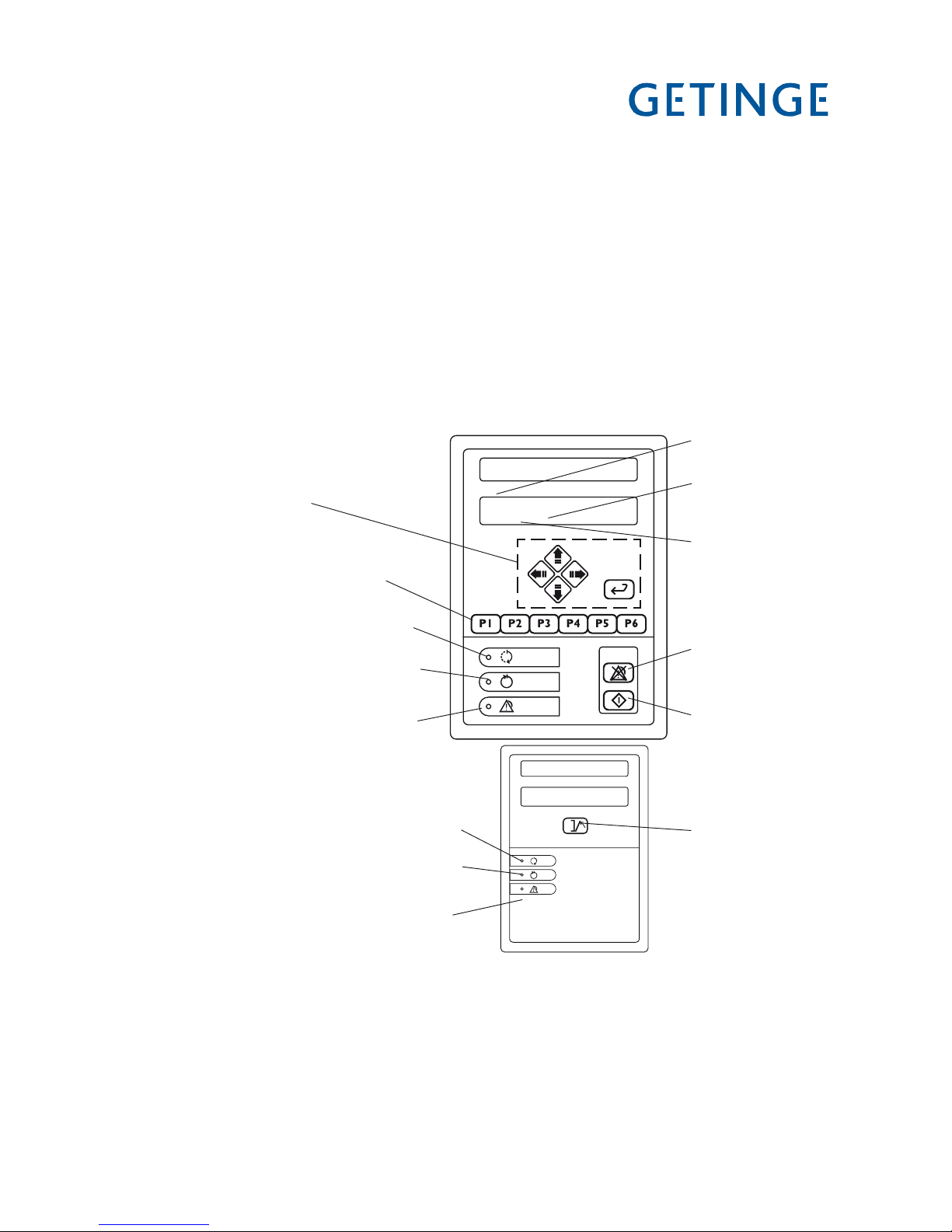
Control system
The machine has an electronically programmable control system which can hold 12 programs. The control system is operated from the control panels of the machine, to the left
of the door on the soiled side.
Six of these programs can be started with the program selection buttons. With 1-6
you can choose up to six programs. If the control system has more programs, the subsequent ones are chosen from a scrollable list. You can reach the list of available programs
(from standby mode), by pressing S twice and choosing a program with J or H.
ConrmthechosenprogramwithS .
The machine comes with a number of standard programs in the programmer (see the
appendixforStandardprograms).Parametersintheseprogramscanbemodiedtosuit
the needs of individual users. Individual programs can be created with a PC. An entire
standard program or parts of one can be used as a starting point for programming.
Programming may only be done by an authorized service technician.
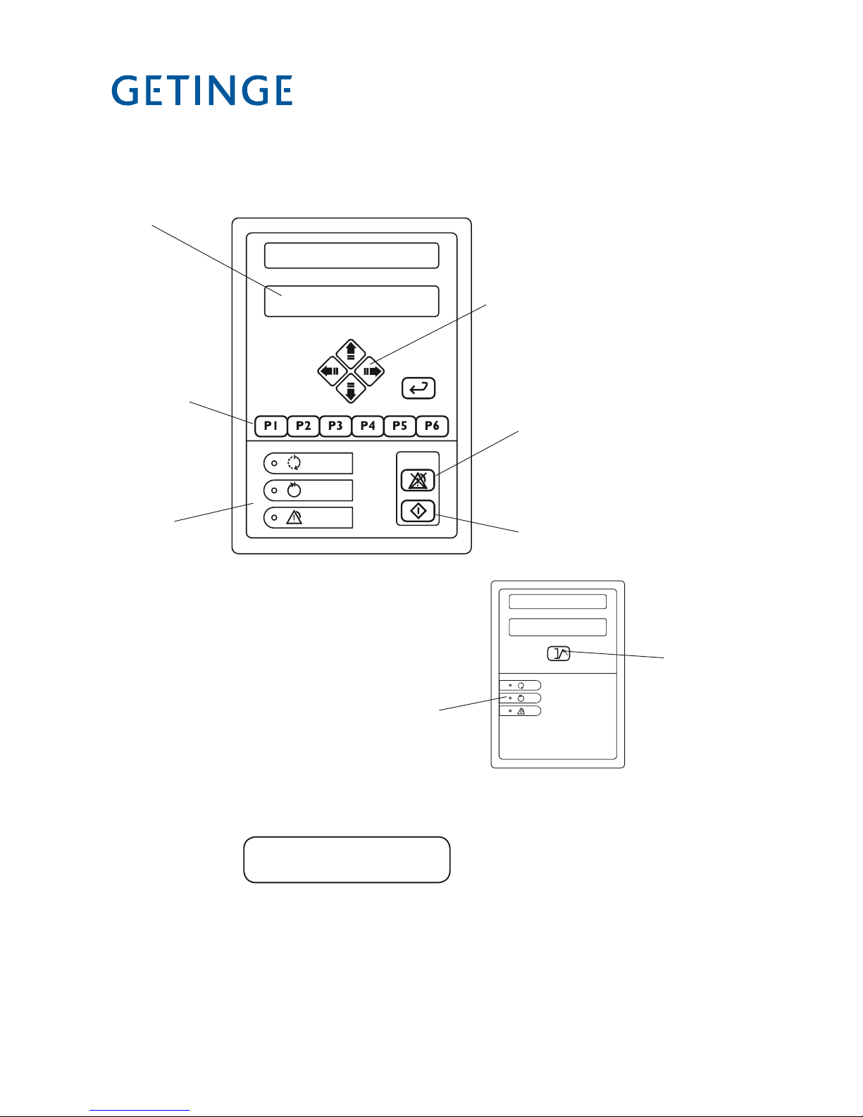
P01 OP-D
60.0C 3
Menu selection buttons
(see Software description
and settings)
Start button for
wash program
Program selection buttons
V1363
Alarm reset button
Green lamp: Program complete
Yellow lamp: Program running
Red lamp: Fault code indication
Actual temperature
in the chamber
Phase of the process
Program number
Panel, clean side
P01 OP-D
60.0C 3
Green lamp: Program complete
Yellow lamp: Program running
Red lamp: Fault code indication
Open/close the
door.
<Doc_TEC><Doc_502406700><Rel_B><Lang_GB>
Page 10 of 148
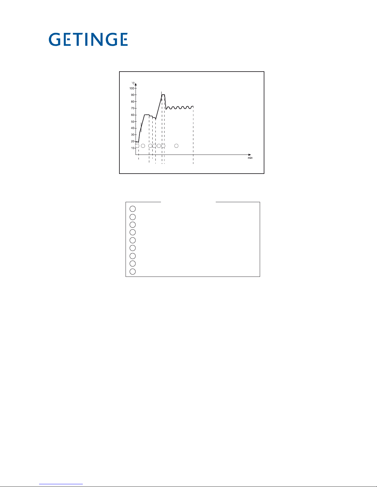
P02
1 Pre-rinse 1
2 Pre-rinse 2
3 Wash
4 Neutralization
5 Post-rinse 1
6 Post-rinse 2
7 Final rinse
8 Disinfection
9 Drying
Program cycles
A Alkaline detergent
B Neutralization
C Instrument milk
(extra equipment)
If instrument milk is
dosed, neutralization
is not dosed.
D Chemical disinfection
Programs are chosen with the program selection buttons and the program is started with
V (starting of a program is indicated by the yellow lamp at Mashingfor5secondsand
then going out). When the program is complete, a green lamp lights up at N and the clean-
side door opens automatically. (The door can stay closed after completion of the process by
a setting in the program. In this case the door is opened via the OP panel on the clean side).
The illustration at the top of the page shows the program sequence in the OP-D program.
Aborting program start
A started program can be aborted within 5 seconds of the machine starting to close the
door on the soiled side. To abort a started program, press V again. During the period
whentheprogramcanbeaborted,ayellowlampashesatM. The door is unlocked and
opened automatically and the machine can be restarted in the usual way.
Aborting a running program
While a program is running, the machine can be stopped with the main switch. This
cuts off the power supply and fault code F00 POWER FAIL is displayed. The alarm is
acknowledged by normal acknowledgement (see the user manual).
CW
+HW
CW HW HW HW
3 5 6 79
A
B
1 8
*The times may vary because of different media.
*
Page 11 of 148
<Doc_TEC><Doc_502406700><Rel_B><Lang_GB>
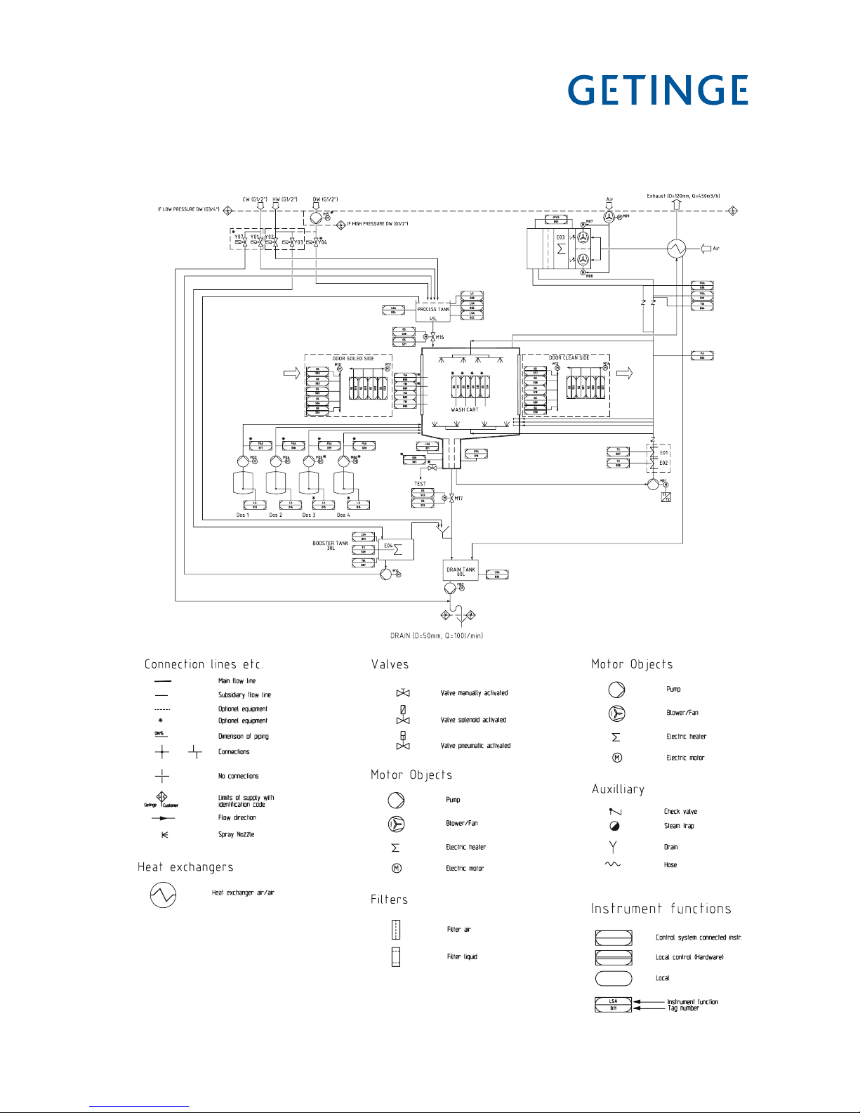
Schematic diagram
Electric heating
Explanation of symbols
V1560
J001
<Doc_TEC><Doc_502406700><Rel_B><Lang_GB>
Page 12 of 148
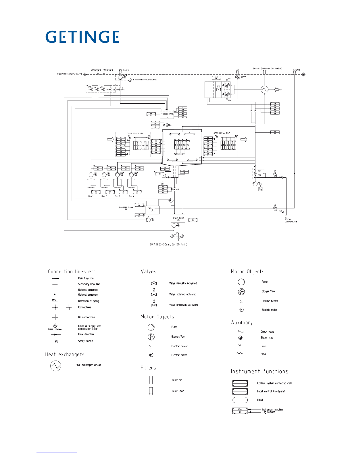
Steam heating
Explanation of symbols
V1560
J002

Page 13 of 148
<Doc_TEC><Doc_502406700><Rel_B><Lang_GB>
Software description and settings
Description
This section describes the PACS 350 control and monitoring system. The purpose of the
control system is to monitor safety and gather information and send it to the executive
components of the washer-disinfector so that a number of disinfection processes can be
performed in accordance with a predetermined template. The order signals are worked
out by the computer program of the control unit in conjunction with measurements of
actual parameter values for the current program. These are usually times, temperatures
and pressures.
Process selection
Several different pieces of equipment can be connected to the control unit for programming, monitoring and documenting the disinfection processes.
The operator communicates with the control unit via a control panel or an ordinary PC.
All operator panels can be used to monitor the processes, since they display all the set
parameter values as well as actual values on request.
Programs,systemdenitionsandprocessdatacanbedocumentedbyconnectinga
printer to the unit. A host computer can also be connected directly to the CPU of the
control system.
When the need arises, a measuring and monitoring system entirely independent of the
control system can be set up by connecting a PACS MONITORING SYSTEM, consisting of CPU, operator panel and connections to the control unit CPU.
The computer contains programs for calibration of the temperature and pressure sensors.
Where alternative correction constants are known, they can be entered manually. The
testing functions include means of activating analog and digital outputs and for reading
analog and digital inputs.
<Doc_TEC><Doc_502406700><Rel_B><Lang_GB>
Page 14 of 148
Control panel
The buttons on the control panel are used to choose programs, navigate the menu tree,
acknowledge fault codes, etc.
Menu selection buttons
Program selection
buttons
V1363
Button to acknowledge
an error message
Button to start
wash programs
Display
Display
The display has two lines, each with a capacity of 20 characters.
P01 OP-SHORT-D
47.0 °C 126
Information or error messages appear on the bottom line and replace the text that would
otherwise appear here.
Program selection buttons
With 1-6 you can choose up to six programs. If the control system has more pro-
grams, the subsequent ones are chosen from a scrollable list. You can reach the list of
available programs (from standby mode), by pressing S twice and choosing a program with J or H.ConrmthechosenprogramwithS .
Indicator lamps
Panel, clean side
P01 OPD
Open the
door.
Indicator
lamps
Panel, soiled side
J018

Page 15 of 148
<Doc_TEC><Doc_502406700><Rel_B><Lang_GB>
Menu selection buttons
Therearevebuttonsfornavigatingthepanel.Thesexedbuttonsarefourarrowbut-
tons that control the cursor (I,K, J and H) and S.
I•• Used to go back one step (up one level) in menus.
If the button is held down for a little longer, you are returned to
the main menu. It also moves the cursor.
K•• Moves the cursor. Not used in menus and lists.
J•• Shows the next object in the list.
H•• Shows the previous object in the list.
S•• Goestothechosenobjectinthelistoropensaeldforediting
ifthereisaneditableeld.

<Doc_TEC><Doc_502406700><Rel_B><Lang_GB>
Page 16 of 148
Scrolling in menus and lists
You can use I, K, J and H to scroll through menus and lists.
You can scroll either line by line or two lines at a time, depending on what is displayed.
The top line of the list may look like the example below.
The angle bracket “>” to the left of the top line shows which object will be chosen if you
press S. Bottom right there is a ”
^
” indicating that there are more objects in the list
which are displayed if you press J.
This is what you see if you are in a list. The “arrows” to the right show that there are
objects both above and below the displayed line.
When you reach the end of the object list, only one up-arrow appears at the right edge of
the display. Menus and lists are “endless”; you can reach the top of the list by pressing
J at the end of the list.
Field editing
Sopensthechoseneldforediting.ThecontentoftheeldischangedwithH
or J.Thesearrowkeysscrollinanendlesslistcontainingnumbers.Whenaeldis
openedforediting,therstcharacterishighlighted.TomovethecursoruseIor K.
Entered values are saved when you press S. On saving, the system checks that the
value is in the permitted range.
>PRINT LAST PRG.
SYSTEM
>SYSTEM ^
APPLIANCE INFO
SYSTEM ^
>APPLIANCE INFO
^
^

Page 17 of 148
<Doc_TEC><Doc_502406700><Rel_B><Lang_GB>
Passwords
There are four passwords with different levels of authorization in the system program.
The operator password has the lowest authority; the programming password has full
authority.
The following password levels are as follows:
Operator - code 558387.•
Supervisor - contact service for code.•
Service - contact service for code.•
Programming - contact service for code.•
Note: In the menu tree, where a password must be entered, there is a letter code (between PW: A-K) which indicates which function the respective password level gives
authorization for.
When a password is being entered, the top line shows “ENTER PASSWORD”. Press
Stoopentheentryeldforediting.EachdigitcanbechangedwithJ and H.
I and K toggle between the digits. Press Stoconrmtheenteredpassword.
Ifthewrongpasswordisentered,“WRONGPASSWORD”appearsontherstline.
Press S to return to the display that shows “ENTER PASSWORD”
Note: The password cannot be changed.
Operator
Supervisor
Code in menu tree Authority to change
A Parameters of type A and to see parameters of type I.
D Acknowledge alarms
Code in menu tree Authority to change
A Parameters
B Calendar (time and date)
C Sensor calibration
D Acknowledge alarms
H Process-criticalcongurations,parametersoftypeP.
J Passwordconguration
K Documentation

<Doc_TEC><Doc_502406700><Rel_B><Lang_GB>
Page 18 of 148
Service
Programming
Code in menu tree Authority to change
A Parameters.
B Calendar (time and date)
C Sensor calibration
D Acknowledge alarms
E Service messages
F DIP switches
G Non-process-criticalsystemcongurations
H Process-criticalcongurations,parametersoftypeP.
J Passwordconguration
K Documentation
Code in menu tree Authority to change
A Parameters.
B Calendar (time and date)
C Sensor calibration
D Acknowledge alarms
E Service messages
F DIP switches
G Non-process-criticalsystemcongurations
H Process-criticalcongurations,parametersoftypeP.
I Programming (phases and programs)
J Passwordconguration
K Documentation

Page 19 of 148
<Doc_TEC><Doc_502406700><Rel_B><Lang_GB>
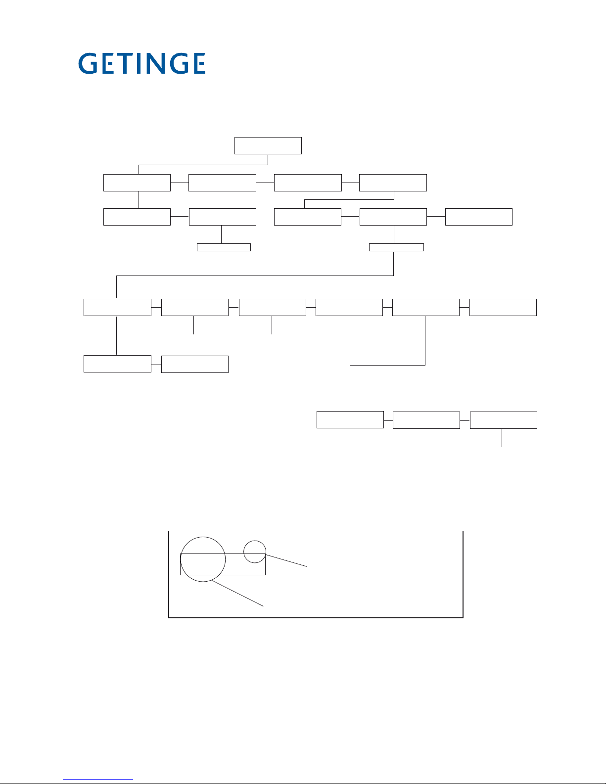
Menu tree
Menu tree _________________________________________________ 20
Main menu 1, Program name (1.1) _______________________________22
Choose a program _____________________________________________22
Change parameters (1.1.2) ______________________________________23
Main menu 2, Machine name (1.2) _______________________________23
Machine information (1.2) _______________________________________23
Main menu 3, Cycle counter (1.3) ________________________________24
Variable list (1.3.1…) ___________________________________________24
Main menu 4, Settings (1.4) ____________________________________25
Print parameters of the chosen cycle (1.4.1) ______________________25
System menu (1.4.2) ___________________________________________25
Calendar menu (1.4.2.1) ________________________________________25
Time menu (1.4.2.1.1) __________________________________________26
Date menu (1.4.2.1.2) __________________________________________ 26
Calibration menu (1.4.2.2) ______________________________________27
Manual calibration menu (1.4.2.2.1) ______________________________27
Automatic calibration menu (1.4.2.2.2) ___________________________28
Calibrate the chosen sensor (1.4.2.2.2.1) _________________________ 28
Choose a sensor (1.4.2.2.2.2) ___________________________________29
Compensation table menu (1.4.2.2.3) ____________________________30
Configuration menu (1.4.2.3) ____________________________________30
Language menu (1.4.2.3.1) _____________________________________30
Date format menu (1.4.2.3.2) ____________________________________31
Unit of pressure menu (1.4.2.3.1.3)_______________________________32
Temperature unit menu (1.4.2.3.1.4) ______________________________33
Printer menu (1.4.2.3.2) ________________________________________ 34
Print mode menu (1.4.2.3.2.1) ___________________________________34
Slow interval menu (1.4.2.3.2.2) _________________________________ 35
Fast interval menu (1.4.2.3.2.3) _________________________________36
Transfer speed menu (1.4.2.3.2.4) _______________________________37
Alarm clock menu (1.4.2.3.3) ____________________________________37
PACS address menu (1.4.2.3.4) _________________________________38
Communication settings COM0 (1.4.2.3.5.1) ______________________39
Communication settings COM1 (1.4.2.3.5.2) ______________________40
Communication mode COM2 (1.4.2.3.5.3) ________________________41
Change cycles (1.4.2.3.6.1) _____________________________________42
DIP switch menu (1.4.2.4) ______________________________________43
Service menu (1.4.2.5) _________________________________________44
Fault log menu (1.4.2.5.1) _______________________________________44
Service message menu (1.4.2.5) _________________________________ 45
Diagnostics menu (1.4.2.5.3) ____________________________________45
Test analog in menu (1.4.2.5.3.1) ________________________________46
Test analog out menu (1.4.2.5.3.2) _______________________________47
Test digital in menu (1.4.2.5.3.3) _________________________________48
Test digital out menu (1.4.2.5.3.4) ________________________________49
Test user flag menu (1.4.2.5.3.5) _________________________________50
Test printer (1.4.2.5.3.7) ________________________________________51
Test LED/buzzer display (1.4.2.5.3.8) _____________________________ 52
Save RAM in flash menu (1.4.2.6) ________________________________ 53
Appliance info (1.4.3)___________________________________________53
<Doc_TEC><Doc_502406700><Rel_B><Lang_GB>
Page 20 of 148
Menu tree
P01 PROGRAM NAME
60.0 C 0
01 MACHINE NAME
02 PHASE NAME
CYCLE COUNTER
00000
SETTINGS
GETINGE PACS 350
VERSION 3.51 (0283)
1.1 1.2 1.3 1.4
SELECT PROGRAM. CHANGE PARAMETERS
ENTER PASSWORD *
SYSTEM APPLIANCE INFO
ENTER PASSWORD *
PRINT LAST PRG
CALENDAR CALIBRATION CONFIGURATION DIP SWITCHES
1.4.2.1 1.4.2.2 1.4.2.3 1.4.2.4
1.1.1 1.1.2 1.4.1 1.4.2 1.4.3
SERVICE
1.4.2.6
SAVE RAM IN FLASH
TIME HH:MM:SS
1.4.2.1.1
DATE YYYY/MM/DD
1.4.2.1.2
See 1.4.2.2
Calibration
See 1.4.2.3
Configuration
SERVICE MESSAGES
1.4.2.5.2
ERROR LOG
1.4.2.5.1
DIAGNOSTICS
1.4.2.5.2
See 1.4.2.5.3
Diagnostics
Shows which menu group the menu belongs to
ERROR LOG
1.4.2.5.1
Shows which process the choice relates to
* Operator password required
** Service personnel password required

Page 21 of 148
<Doc_TEC><Doc_502406700><Rel_B><Lang_GB>
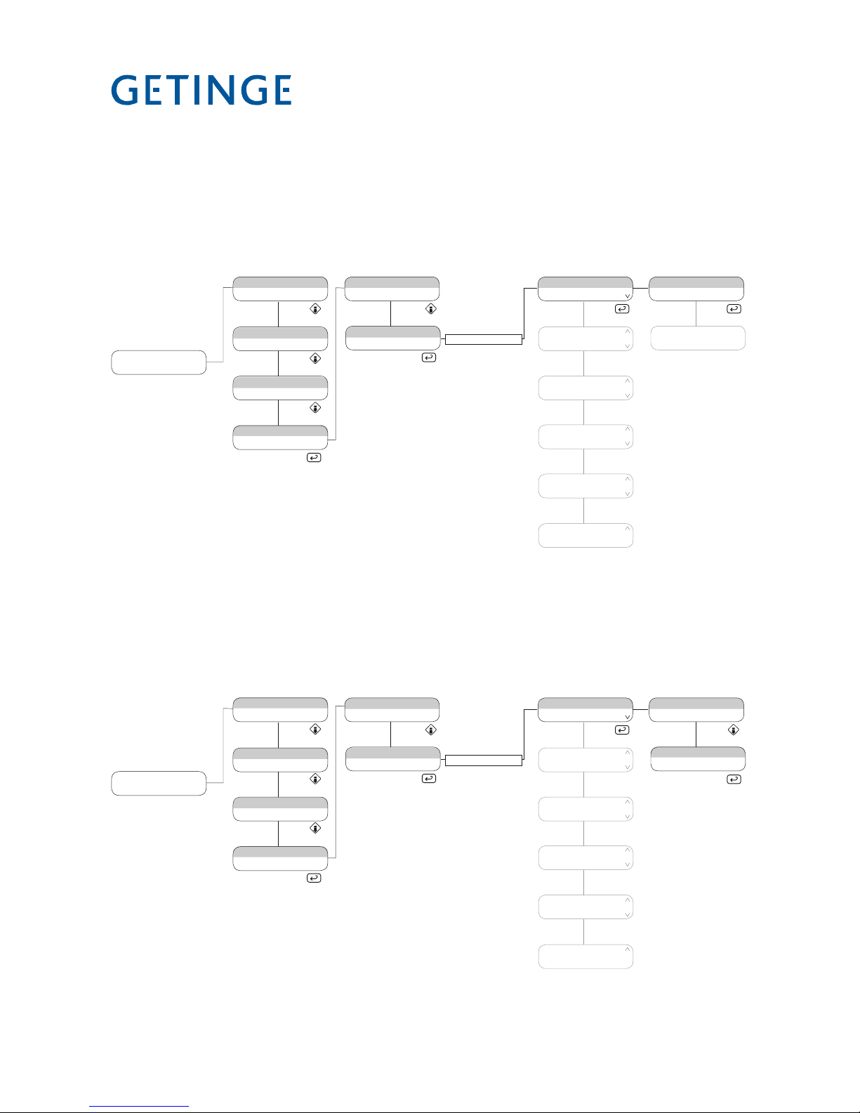
MANUAL CALIBRATION AUTO CALIBRATION COMPENSATION TABLE
CALIBRATION
1.4.2.2.1 1.4.2.2.2 1.4.2.2.3
CONTINUE 1 (32) CHOOSE SENSOR
1.4.2.2.2.1
1.4.2.2
1.4.2.2.2.2
1.4.2.2 CALIBRATION
1.4.2.3 CONFIGURATION
LANGUAGE & DATE UNIT PRINTER ALARM CLOCK
CONFIGURATION
1.4.2.3.1 1.4.2.3.2 1.4.2.3.3
PRINTER MODE SLOW INTERVAL
1.4.2.3.2.1
1.4.2.3
1.4.2.3.2.2
PACS ADDRESS
1.4.2.3.4
COMMUNICATION
1.4.2.3.5
CHANGE CYCLES
1.4.2.3.6
FAST INTERVAL
1.4.2.3.2.3
PRINTER & SPEED
1.4.2.3.2.4
LANGUAGE DATE FORMAT
1.4.2.3.1.1 1.4.2.3.1.2
UNIT OF PRESSURE
1.4.2.3.1.3
UNIT OF TEMPERATURE
1.4.2.3.1.4
1.4.2.5.3 DIAGNOSTICS
ANALOG IN ANALOG OUT DIGITAL IN
DIAGNOSTICS
1.4.2.5.3.1
1.4.2.5.3
DIGITAL OUT USER FLAG
PRINTERSYSTEM FLAG
AUTO CALIBRATION
CONTINUE 1 (32) CHOOSE SENSOR
1.4.2.5.3.2 1.4.2.5.3.3 1.4.2.5.3.4 1.4.2.5.3.5
1.4.2.5.3.6 1.4.2.5.3.7
1.4.2.2.2
1.4.2.2.2.1 1.4.2.2.2.2
COMPENSATION TABLE
1.4.2.2.3

<Doc_TEC><Doc_502406700><Rel_B><Lang_GB>
Page 22 of 148
Main menu 1, Program name (1.1)
In standby mode the top line of the display shows the name of the last cycle
chosen. The second row shows two preselected values, normally this is the
temperature in the machine and the cycle counter. The main purpose of this
menu is to choose a wash cycle and to be able to change parameters.
This menu has two submenus.
SELECT PROGRAM (1.1.1)
CHANGE PARAMETERS (1.1.2)
Select the program.
In the main menu 1 press S to move to the SELECT PROGRAM menu then
press enter again to reach the various programs. Use the
J and H buttons to
highlight the program you want to use. To select a program press S. The cycles
are pre-configured in the program and cannot be changed by the operator.
1.1
1.2
1.1.1
1.3
1.4
GETINGE PACS 350
VERSION 3.51 (0283)
P01 PROGRAM NAME
PARAM1 PARAM2
MACHINE NAME
PHASE NAME
CYCLE COUNTER
00000
SETTINGS
SELECT PROGRAM.
1.1.1.1
01 PROGRAM #01
02 PROGRAM #02
1.1.1.2
1.1.1.3
02 PROGRAM #02
03 PROGRAM #03
03 PROGRAM #03
04 PROGRAM #04
1.1.1.9
1.1.1.10
1.1.1.11
09 PROGRAM #09
10 PROGRAM #10
10 PROGRAM #10
11 PROGRAM #11
11 PROGRAM #11
12 PROGRAM #12
1.1.2
CHANGE PARAMETERS

Page 23 of 148
<Doc_TEC><Doc_502406700><Rel_B><Lang_GB>
1.1
1.2
1.1.1
1.3
1.4
GETINGE PACS 350
VERSION 3.51 (0283)
P01 PROGRAM NAME
PARAM1 PARAM2
MACHINE NAME
PHASE NAME
CYCLE COUNTER
00000
SETTINGS
SELECT PROGRAM.
1.1.2.1
WASH DOS TEMP
035.0C
1.1.2.2
1.1.2.3
PARAMETER #02
PARAMETER #03
PARAMETER #03
PARAMETER #04
1.1.2.57
1.1.2.58
1.1.2.59
PARAMETER #56
PARAMETER #57
PARAMETER #57
PARAMETER #58
PARAMETER #58
PARAMETER #59
1.1.2
CHANGE PARAMETERS
Change parameters (1.1.2)
In main menu 1, press S to go to the SELECT PROGRAM menu. Then press
J to activate “CHANGE PARAMETERS”. To select a program, press S again.
Every cycle has a set of preset parameters. When a cycle has been chosen as
explained in the previous section, the parameters appear on the display. The
number of the parameter depends on how the cycle was configured when it was
created in the program.
The parameters that have an “A” indication in the bottom right corner are
adjustable. With a class A password, the value can be changed by pressing
S.
If an“I” is displayed in the same position then the parameters are only
information.
P parameters can only be changed with class A + H passwords.
ENTER PASSWORD *
* Operator password required
Main menu 2, Machine name (1.2)
Main menu 2 shows information about the machine and the current phase. The
information cannot be changed.
Machine information (1.2)
The top line shows name/ID of the disinfection program and the bottom line
shows the current phase.
GETINGE PACS 350
VERSION 3.51 (0283)
P01 PROGRAM NAME
PARAM1 PARAM2
MACHINE NAME
PHASE NAME
CYCLE COUNTER
00000
SETTINGS

<Doc_TEC><Doc_502406700><Rel_B><Lang_GB>
Page 24 of 148
Main menu 3, Cycle counter (1.3)
In this menu, a selectable variable can be displayed. The top line shows the
name of the variable and the bottom line shows the value of the variable.
Variable list (1.3.1…)
There is a configured number of variables for every cycle. This list is only for
information about the variables. To choose the variable you want to see, press
J or H, then press S to display the chosen variable.
1.1
1.2
1.3
1.4
GETINGE PACS 350
VERSION 3.51 (0283)
P01 PROGRAM NAME
PARAM1 PARAM2
MACHINE NAME
PHASE NAME
CYCLE COUNTER
00000
SETTINGS
1.3.1
CYCLE COUNTER
00000
1.3.2
1.3.3
VARIABLE
VALUE #02
VARIABLE
VALUE #02
1.3.42
1.3.43
1.3.44
VARIABLE
VALUE #42
VARIABLE
VALUE #43
NO VARIABLE
>

Page 25 of 148
<Doc_TEC><Doc_502406700><Rel_B><Lang_GB>
Main menu 4, Settings (1.4)
Main menu 4 is the settings menu for the machine. The settings menu has three
submenus.
Print the parameters of the chosen cycle (1.4.1)
System setting menus. (1.4.2)
Appliance information. (1.4.3)
Print parameters of the chosen cycle (1.4.1)
When a cycle has been chosen in main menu 1, the parameters of that cycle can
be printed out.
Press
J three times to reach the settings menu, then press S to choose
settings. Pressing
S once more brings up the printing screen. Use I or K
to choose “YES” to start printing or “NO” if you do not want to print the chosen
cycle.
System menu (1.4.2)
The system settings menu has six submenus.
A calendar where you can enter the date and time. (1.4.2.1)
Calibration of analog entry values. (1.4.2.2)
Configuration of devices such as printer, alarms,
alarm clocks and node addresses. (1.4.2.3)
DIP switches. (1.4.2.4)
Service menu with fault message, service message
and diagnostics. (1.4.2.5)
Save RAM in flash. (1.4.2.6)
Calendar menu (1.4.2.1)
The time and date can be set in this menu.
There is a submenu for each function.
Set time. (1.4.2.1.1)
Set date. (1.4.2.1.2)
1.1
1.2
1.3
1.4
GETINGE PACS 350
VERSION 3.51 (0283)
P01 PROGRAM NAME
PARAM1 PARAM2
MACHINE NAME
PHASE NAME
CYCLE COUNTER
00000
SETTINGS
1.3.1
PRINT LAST CYCLE
SYSTEM
1.3.2
1.3.3
SYSTEM
ABOUT
SYSTEM
ABOUT
1.3.3
PRINT LAST CYCLE
YES NO
<Doc_TEC><Doc_502406700><Rel_B><Lang_GB>
Page 26 of 148
Time menu (1.4.2.1.1)
To set the time, follow the instructions in the menu tree below. Enter password
and press S when the calendar menu has been chosen. To set the time, press
S. To change the time press H and J until the desired time is displayed.
Then use
I or K to change field. When the value is correctly set, press S to
confirm the change.
1.1
1.2
1.4.1
1.3
1.4
GETINGE PACS 350
VERSION 3.51 (0283)
P01 PROGRAM NAME
PARAM1 PARAM2
MACHINE NAME
PHASE NAME
CYCLE COUNTER
00000
SETTINGS
PRINT LAST CYCLE
SYSTEM
1.4.2.1
CALENDAR
CALIBRATION
1.4.2.2
1.4.2.3
CALIBRATION
CONFIGURATION
CONFIGURATION
DIP SWITCHES
1.4.2.4
1.4.2.5
1.4.2.6
DIP SWITCHES
SERVICE
SERVICE
SAVE RAM IN FLASH
SERVICE
SAVE RAM IN FLASH
1.4.2
SYSTEM
ABOUT
ENTER PASSWORD *
* Service personnel password required
1.4.2.1.1
TIME HH:MM:SS
15:45:50
1.4.2.1.2
DATE YYYY/MM/DD
2006/08/23
Date menu (1.4.2.1.2)
To set the date, follow the instructions in the menu tree below. Enter password
and press S when the calendar menu has been chosen. To set the date, press
S. To change the time press H and J until the desired date is displayed.
Then use
I or K to change field. When the value is correctly set, press S to
confirm the change.
1.1
1.2
1.4.1
1.3
1.4
GETINGE PACS 350
VERSION 3.51 (0283)
P01 PROGRAM NAME
PARAM1 PARAM2
MACHINE NAME
PHASE NAME
CYCLE COUNTER
00000
SETTINGS
PRINT LAST CYCLE
SYSTEM
1.4.2.1
CALENDAR
CALIBRATION
1.4.2.2
1.4.2.3
CALIBRATION
CONFIGURATION
CONFIGURATION
DIP SWITCHES
1.4.2.4
1.4.2.5
1.4.2.6
DIP SWITCHES
SERVICE
SERVICE
SAVE RAM IN FLASH
SERVICE
SAVE RAM IN FLASH
1.4.2
SYSTEM
ABOUT
ENTER PASSWORD *
1.4.2.1.1
TIME HH:MM:SS
15:45:50
1.4.2.1.2
DATE YYYY/MM/DD
2006/08/23
* Service personnel password required

Page 27 of 148
<Doc_TEC><Doc_502406700><Rel_B><Lang_GB>
Calibration menu (1.4.2.2)
The calibration menu is used to calibrate analog entry values. There are three
submenus for calibration.
Manual calibration. (1.4.2.2.1)
Automatic calibration. (1.4.2.2.2)
Adjusting the compensation table. (1.4.2.2.3)
Manual calibration menu (1.4.2.2.1)
In manual calibration, two values for A-Gain and B-offset can be entered
manually. To access manual calibration, follow the instructions in the menu tree
below. To change values, press
H and J. Then use I or K to change field.
When the value is correctly set, press S to confirm the change.
1.1
1.2
1.4.1
1.3
1.4
GETINGE PACS 350
VERSION 3.51 (0283)
P01 PROGRAM NAME
PARAM1 PARAM2
MACHINE NAME
PHASE NAME
CYCLE COUNTER
00000
SETTINGS
PRINT LAST CYCLE
SYSTEM
1.4.2.1
CALENDAR
CALIBRATION
1.4.2.2
1.4.2.3
CALIBRATION
CONFIGURATION
CONFIGURATION
DIP SWITCHES
1.4.2.4
1.4.2.5
1.4.2.6
DIP SWITCHES
SERVICE
SERVICE
SAVE RAM IN FLASH
SERVICE
SAVE RAM IN FLASH
1.4.2
SYSTEM
ABOUT
ENTER PASSWORD *
1.4.2.2.1
1.4.2.2.2
1.4.2.2.3
MANUAL CALIBRATION
AUTO CALIBRATION
AUTO CALIBRATION
COMPENSATION TABLE
AUTO CALIBRATION
COMPENSATION TABLE
1.4.2.2.1.1
1.4.2.2.1.2
1.4.2.2.1.3
00 CALIBRATION TYPE
OFFSET SPAN
01 CALIBRATION TYPE
OFFSET SPAN
02 CALIBRATION TYPE
OFFSET SPAN
1.4.2.2.1.32
31 CALIBRATION TYPE
OFFSET SPAN
* Service personnel password required

<Doc_TEC><Doc_502406700><Rel_B><Lang_GB>
Page 28 of 148
Automatic calibration menu (1.4.2.2.2)
This menu has two submenus.
Continue. (1.4.2.2.2.1)
Choose a sensor. (1.4.2.2.2.2)
With automatic calibration, you must choose a sensor for calibration. Do this in
the Choose a sensor menu. When one or more sensors have been chosen for
calibration, the Continue menu shows how many sensors have been chosen and
an arrow appears on the right of the display. When you quit the calibration menu,
all chosen sensors are deselected.
Calibrate the chosen sensor (1.4.2.2.2.1)
When one or more similar sensors have been chosen (see 1.4.2.2.2.2), this
is shown by an arrow at the right-hand edge of the display, beside the word
“Continue” on the first line. Pressing S displays the low reference value. When
the value is stable, press S to confirm it. Now the high reference value is
displayed. When the value is stable, press S to confirm it. Now you have the
option of printing out the calibration value by highlighting “YES” for printout or
“NO” for no printout.
1.1
1.2
1.4.1
1.3
1.4
GETINGE PACS 350
VERSION 3.51 (0283)
P01 PROGRAM NAME
PARAM1 PARAM2
MACHINE NAME
PHASE NAME
CYCLE COUNTER
00000
SETTINGS
PRINT LAST CYCLE
SYSTEM
1.4.2.1
CALENDAR
CALIBRATION
1.4.2.2
1.4.2.3
CALIBRATION
CONFIGURATION
CONFIGURATION
DIP SWITCHES
1.4.2.4
1.4.2.5
1.4.2.6
DIP SWITCHES
SERVICE
SERVICE
SAVE RAM IN FLASH
SERVICE
SAVE RAM IN FLASH
1.4.2
SYSTEM
ABOUT
ENTER PASSWORD *
1.4.2.2.1
1.4.2.2.2
1.4.2.2.3
MANUAL CALIBRATION
AUTO CALIBRATION
AUTO CALIBRATION
COMPENSATION TABLE
AUTO CALIBRATION
COMPENSATION TABLE
1.4.2.2.2.1
1.4.2.2.1.3
CONTINUE 1 (32)
CHOOSE SENSOR
CONTINUE 1 (32)
CHOOSE SENSOR
1.4.2.2.2.1.1
1.4.2.2.2.1.2
1.4.2.2.2.1.3
LOW REFERENCE
VALUE %
HIGH REFERENCE
VALUE %
PRINT CALIBRATION
YES NO
>
>
* Service personnel password required

Page 29 of 148
<Doc_TEC><Doc_502406700><Rel_B><Lang_GB>
Choose a sensor (1.4.2.2.2.2)
Press S when Choose sensor is highlighted under automatic calibration.
Confirm the choice by placing the cursor on “YES” and pressing S again. The
sensor has now been chosen. Note that more than one sensor can be chosen at
the same time. If more than one sensor is chosen at the same time, they must be
of a similar type.
1.1
1.2
1.4.1
1.3
1.4
GETINGE PACS 350
VERSION 3.51 (0283)
P01 PROGRAM NAME
PARAM1 PARAM2
MACHINE NAME
PHASE NAME
CYCLE COUNTER
00000
SETTINGS
PRINT LAST CYCLE
SYSTEM
1.4.2.1
CALENDAR
CALIBRATION
1.4.2.2
1.4.2.3
CALIBRATION
CONFIGURATION
CONFIGURATION
DIP SWITCHES
1.4.2.4
1.4.2.5
1.4.2.6
DIP SWITCHES
SERVICE
SERVICE
SAVE RAM IN FLASH
SERVICE
SAVE RAM IN FLASH
1.4.2
SYSTEM
ABOUT
ENTER PASSWORD *
1.4.2.2.1
1.4.2.2.2
1.4.2.2.3
MANUAL CALIBRATION
AUTO CALIBRATION
AUTO CALIBRATION
COMPENSATION TABLE
AUTO CALIBRATION
COMPENSATION TABLE
1.4.2.2.2.1
1.4.2.2.2.2
CONTINUE 1 (32)
CHOOSE SENSOR
1.4.2.2.2.2.1
1.4.2.2.2.2.2
1.4.2.2.2.2.3
00 CALIBRATION TYPE
VALUE % CAL NO
01 CALIBRATION TYPE
VALUE % CAL NO
02 CALIBRATION TYPE
VALUE % CAL NO
>
CONTINUE 1 (32)
CHOOSE SENSOR
>
1.4.2.2.2.2.31
31 CALIBRATION TYPE
VALUE % CAL NO
* Service personnel password required

<Doc_TEC><Doc_502406700><Rel_B><Lang_GB>
Page 30 of 148
Compensation table menu (1.4.2.2.3)
This menu is not applicable on this machine.
Configuration menu (1.4.2.3)
The configuration display is used to set language, and units. The printer is also
set here. The alarm clock and PACS addresses are also set here. There are four
submenus.
Language. (1.4.2.3.1)
Date format. (1.4.2.3.2)
Unit of pressure. (1.4.2.3.3)
Unit of temperature (1.4.2.3.4)
Language menu (1.4.2.3.1)
Language settings for the various displays can be accessed in this menu. Press
S and choose the required language. To confirm, press S.
1.1
1.2
1.4.1
1.3
1.4
GETINGE PACS 350
VERSION 3.51 (0283)
P01 PROGRAM NAME
PARAM1 PARAM2
MACHINE NAME
PHASE NAME
CYCLE COUNTER
00000
SETTINGS
PRINT LAST CYCLE
SYSTEM
1.4.2.1
CALENDAR
CALIBRATION
1.4.2.2
1.4.2.3
CALIBRATION
CONFIGURATION
CONFIGURATION
DIP SWITCHES
1.4.2.4
1.4.2.5
1.4.2.6
DIP SWITCHES
SERVICE
SERVICE
SAVE RAM IN FLASH
SERVICE
SAVE RAM IN FLASH
1.4.2
SYSTEM
ABOUT
ENTER PASSWORD *
1.4.2.3.1
1.4.2.3.2
1.4.2.3.3
LANGUAGE DATE UNIT
PRINTER
ALARM CLOCK
PACS ADDRESS
1.4.2.3.1.1
LANGUAGE
SWEDISH
1.4.2.3.4
PACS ADDRESS
COMMUNICATION
1.4.2.3.5
PACS ADDRESS
COMMUNICATION
1.4.2.3.1.2
DATE FORMAT
YYYY/MM/DD
1.4.2.3.1.3
UNIT OF PRESSURE
KPA
1.4.2.3.1.4
UNIT OF TEMPERATURE
C
PRINTER
ALARM CLOCK
* Service personnel password required

Page 31 of 148
<Doc_TEC><Doc_502406700><Rel_B><Lang_GB>
Date format menu (1.4.2.3.2)
The date format is chosen from this menu. There are three date formats: Press
S to see the different formats. Then choose the date format you want. To
confirm, press S.
YYYY/MM/DD (1.4.2.3.2.1)
MM/DD/YYYY (1.4.2.3.2.2)
DD/MM/YYYY. (1.4.2.3.2.3)
1.1
1.2
1.4.1
1.3
1.4
GETINGE PACS 350
VERSION 3.51 (0283)
P01 PROGRAM NAME
PARAM1 PARAM2
MACHINE NAME
PHASE NAME
CYCLE COUNTER
00000
SETTINGS
PRINT LAST CYCLE
SYSTEM
1.4.2.1
CALENDAR
CALIBRATION
1.4.2.2
1.4.2.3
CALIBRATION
CONFIGURATION
CONFIGURATION
DIP SWITCHES
1.4.2.4
1.4.2.5
1.4.2.6
DIP SWITCHES
SERVICE
SERVICE
SAVE RAM IN FLASH
SERVICE
SAVE RAM IN FLASH
1.4.2
SYSTEM
ABOUT
ENTER PASSWORD *
1.4.2.3.1
1.4.2.3.2
1.4.2.3.3
LANGUAGE DATE UNIT
PRINTER
ALARM CLOCK
PACS ADDRESS
1.4.2.3.1.1
LANGUAGE
SWEDISH
1.4.2.3.4
PACS ADDRESS
COMMUNICATION
1.4.2.3.5
PACS ADDRESS
COMMUNICATION
1.4.2.3.1.2
DATE FORMAT
YYYY/MM/DD
1.4.2.3.1.3
UNIT OF PRESSURE
KPA
1.4.2.3.1.4
UNIT OF TEMPERATURE
C
PRINTER
ALARM CLOCK
1.4.2.3.1.2.1
DATE FORMAT
YYYY/MM/DD
1.4.2.3.1.2.2
DATE FORMAT
MM/DD/YYYY
1.4.2.3.1.2.3
DATE FORMAT
DD/MM/YYYY
* Service personnel password required

<Doc_TEC><Doc_502406700><Rel_B><Lang_GB>
Page 32 of 148
Unit of pressure menu (1.4.2.3.1.3)
Three units of pressure are available: Press S to access the menu with the
various units, then choose the unit you want. To confirm, press S. Note: This
only shows the available units. The value of these units is not converted.
BAR (1.4.2.3.1.3.1)
KPA (1.4.2.3.1.3.2)
PSI (1.4.2.3.1.3.3)
1.1
1.2
1.4.1
1.3
1.4
GETINGE PACS 350
VERSION 3.51 (0283)
P01 PROGRAM NAME
PARAM1 PARAM2
MACHINE NAME
PHASE NAME
CYCLE COUNTER
00000
SETTINGS
PRINT LAST CYCLE
SYSTEM
1.4.2.1
CALENDAR
CALIBRATION
1.4.2.2
1.4.2.3
CALIBRATION
CONFIGURATION
CONFIGURATION
DIP SWITCHES
1.4.2.4
1.4.2.5
1.4.2.6
DIP SWITCHES
SERVICE
SERVICE
SAVE RAM IN FLASH
SERVICE
SAVE RAM IN FLASH
1.4.2
SYSTEM
ABOUT
ENTER PASSWORD *
1.4.2.3.1
1.4.2.3.2
1.4.2.3.3
LANGUAGE DATE UNIT
PRINTER
ALARM CLOCK
PACS ADDRESS
1.4.2.3.1.1
LANGUAGE
SWEDISH
1.4.2.3.4
PACS ADDRESS
COMMUNICATION
1.4.2.3.5
PACS ADDRESS
COMMUNICATION
1.4.2.3.1.2
DATE FORMAT
YYYY/MM/DD
1.4.2.3.1.3
UNIT OF PRESSURE
KPA
1.4.2.3.1.4
UNIT OF TEMPERATURE
C
PRINTER
ALARM CLOCK
1.4.2.3.1.3.1
UNIT OF PRESSURE
BAR
1.4.2.3.1.3.2
UNIT OF PRESSURE
PSI
1.4.2.3.1.3.3
UNIT OF PRESSURE
PSI
* Service personnel password required

Page 33 of 148
<Doc_TEC><Doc_502406700><Rel_B><Lang_GB>
Unit of temp menu (1.4.2.3.1.4)
There is a choice of two units of temperature. Press S to see the two units.
Choose the unit you want to use and press S to confirm.
Note: This only shows the available units. The value of these units is not
converted.
Celsius. (1.4.2.3.1.4.1)
Fahrenheit. (1.4.2.3.1.4.2)
1.1
1.2
1.4.1
1.3
1.4
GETINGE PACS 350
VERSION 3.51 (0283)
P01 PROGRAM NAME
PARAM1 PARAM2
MACHINE NAME
PHASE NAME
CYCLE COUNTER
00000
SETTINGS
PRINT LAST CYCLE
SYSTEM
1.4.2.1
CALENDAR
CALIBRATION
1.4.2.2
1.4.2.3
CALIBRATION
CONFIGURATION
CONFIGURATION
DIP SWITCHES
1.4.2.4
1.4.2.5
1.4.2.6
DIP SWITCHES
SERVICE
SERVICE
SAVE RAM IN FLASH
SERVICE
SAVE RAM IN FLASH
1.4.2
SYSTEM
ABOUT
ENTER PASSWORD *
1.4.2.3.1
1.4.2.3.2
1.4.2.3.3
LANGUAGE DATE UNIT
PRINTER
ALARM CLOCK
PACS ADDRESS
1.4.2.3.1.1
LANGUAGE
SWEDISH
1.4.2.3.4
PACS ADDRESS
COMMUNICATION
1.4.2.3.5
COMMUNICATION
CHANGE CYCLES
1.4.2.3.1.2
DATE FORMAT
YYYY/MM/DD
1.4.2.3.1.3
UNIT OF PRESSURE
KPA
1.4.2.3.1.4
UNIT OF TEMPERATURE
C
PRINTER
ALARM CLOCK
1.4.2.3.1.4.1
UNIT OF TEMPERATURE
C
1.4.2.3.1.4.2
UNIT OF TEMPERATURE
F
* Service personnel password required
1.4.2.3.6
COMMUNICATION
CHANGE CYCLES

<Doc_TEC><Doc_502406700><Rel_B><Lang_GB>
Page 34 of 148
Printer menu (1.4.2.3.2)
All settings for printer and logs are made in this section. There are four
submenus:
Printer mode. (1.4.2.3.2.1)
Slow interval (1.4.2.3.2.2)
Fast interval (1.4.2.3.2.3)
Printer transfer speed. (1.4.2.3.2.4)
Print mode menu (1.4.2.3.2.1)
This menu has only one option. Only process values are printed out.
1.1
1.2
1.4.1
1.3
1.4
GETINGE PACS 350
VERSION 3.51 (0283)
P01 PROGRAM NAME
PARAM1 PARAM2
MACHINE NAME
PHASE NAME
CYCLE COUNTER
00000
SETTINGS
PRINT LAST CYCLE
SYSTEM
1.4.2.1
CALENDAR
CALIBRATION
1.4.2.2
1.4.2.3
CALIBRATION
CONFIGURATION
CONFIGURATION
DIP SWITCHES
1.4.2.4
1.4.2.5
1.4.2.6
DIP SWITCHES
SERVICE
SERVICE
SAVE RAM IN FLASH
SERVICE
SAVE RAM IN FLASH
1.4.2
SYSTEM
ABOUT
ENTER PASSWORD *
1.4.2.3.1
1.4.2.3.2
1.4.2.3.3
LANGUAGE DATE UNIT
PRINTER
ALARM CLOCK
PACS ADDRESS
1.4.2.3.2.1
PRINT MODE
1.4.2.3.4
PACS ADDRESS
COMMUNICATION
1.4.2.3.2.2
SLOW INTERVAL
01:00
1.4.2.3.2.3
FAST INTERVAL
20:00
1.4.2.3.2.4
PRINTER TRANSF. SP.
9600
PRINTER
ALARM CLOCK
* Service personnel password required
1.4.2.3.5
COMMUNICATION
CHANGE CYCLES
1.4.2.3.6
COMMUNICATION
CHANGE CYCLES

Page 35 of 148
<Doc_TEC><Doc_502406700><Rel_B><Lang_GB>
1.1
1.2
1.4.1
1.3
1.4
GETINGE PACS 350
VERSION 3.51 (0283)
P01 PROGRAM NAME
PARAM1 PARAM2
MACHINE NAME
PHASE NAME
CYCLE COUNTER
00000
SETTINGS
PRINT LAST CYCLE
SYSTEM
1.4.2.1
CALENDAR
CALIBRATION
1.4.2.2
1.4.2.3
CALIBRATION
CONFIGURATION
CONFIGURATION
DIP SWITCHES
1.4.2.4
1.4.2.5
1.4.2.6
DIP SWITCHES
SERVICE
SERVICE
SAVE RAM IN FLASH
SERVICE
SAVE RAM IN FLASH
1.4.2
SYSTEM
ABOUT
ENTER PASSWORD *
1.4.2.3.1
1.4.2.3.2
1.4.2.3.3
LANGUAGE DATE UNIT
PRINTER
ALARM CLOCK
PACS ADDRESS
1.4.2.3.2.1
PRINT MODE
1.4.2.3.4
PACS ADDRESS
COMMUNICATION
1.4.2.3.2.2
SLOW INTERVAL
01:00
1.4.2.3.2.3
FAST INTERVAL
20:00
1.4.2.3.2.4
PRINTER TRANSF. SP.
9600
PRINTER
ALARM CLOCK
Slow interval menu(1.4.2.3.2.2)
The speed of the slow interval log times is shown here. The phases that use this
time speed are pre-configured in the program for each phase.
* Service personnel password required
1.4.2.3.5
COMMUNICATION
CHANGE CYCLES
1.4.2.3.6
COMMUNICATION
CHANGE CYCLES

<Doc_TEC><Doc_502406700><Rel_B><Lang_GB>
Page 36 of 148
1.1
1.2
1.4.1
1.3
1.4
GETINGE PACS 350
VERSION 3.51 (0283)
P01 PROGRAM NAME
PARAM1 PARAM2
MACHINE NAME
PHASE NAME
CYCLE COUNTER
00000
SETTINGS
PRINT LAST CYCLE
SYSTEM
1.4.2.1
CALENDAR
CALIBRATION
1.4.2.2
1.4.2.3
CALIBRATION
CONFIGURATION
CONFIGURATION
DIP SWITCHES
1.4.2.4
1.4.2.5
1.4.2.6
DIP SWITCHES
SERVICE
SERVICE
SAVE RAM IN FLASH
SERVICE
SAVE RAM IN FLASH
1.4.2
SYSTEM
ABOUT
ENTER PASSWORD *
1.4.2.3.1
1.4.2.3.2
1.4.2.3.3
LANGUAGE DATE UNIT
PRINTER
ALARM CLOCK
PACS ADDRESS
1.4.2.3.2.1
PRINT MODE
1.4.2.3.4
PACS ADDRESS
COMMUNICATION
1.4.2.3.2.2
SLOW INTERVAL
01:00
1.4.2.3.2.3
FAST INTERVAL
20:00
1.4.2.3.2.4
PRINTER TRANSF. SP.
9600
PRINTER
ALARM CLOCK
Fast interval menu(1.4.2.3.2.3)
The speed of the fast interval log times is shown here. The phases that use this
time speed are pre-configured in the program for each phase.
* Service personnel password required
1.4.2.3.5
COMMUNICATION
CHANGE CYCLES
1.4.2.3.6
COMMUNICATION
CHANGE CYCLES

Page 37 of 148
<Doc_TEC><Doc_502406700><Rel_B><Lang_GB>
1.1
1.2
1.4.1
1.3
1.4
GETINGE PACS 350
VERSION 3.51 (0283)
P01 PROGRAM NAME
PARAM1 PARAM2
MACHINE NAME
PHASE NAME
CYCLE COUNTER
00000
SETTINGS
PRINT LAST CYCLE
SYSTEM
1.4.2.1
CALENDAR
CALIBRATION
1.4.2.2
1.4.2.3
CALIBRATION
CONFIGURATION
CONFIGURATION
DIP SWITCHES
1.4.2.4
1.4.2.5
1.4.2.6
DIP SWITCHES
SERVICE
SERVICE
SAVE RAM IN FLASH
SERVICE
SAVE RAM IN FLASH
1.4.2
SYSTEM
ABOUT
ENTER PASSWORD *
1.4.2.3.1
1.4.2.3.2
1.4.2.3.3
LANGUAGE DATE UNIT
PRINTER
ALARM CLOCK
PACS ADDRESS
1.4.2.3.2.1
PRINT MODE
1.4.2.3.4
PACS ADDRESS
COMMUNICATION
1.4.2.3.2.2
SLOW INTERVAL
01:00
1.4.2.3.2.3
FAST INTERVAL
20:00
1.4.2.3.2.4
PRINTER TRANSF. SP.
9600
PRINTER
ALARM CLOCK
Transfer speed menu (1.4.2.3.2.4)
You can choose the transfer speed for the printer in this menu. There are four
transfer speeds:
1200. (1.4.2.3.2.4.1)
2400. (1.4.2.3.2.4.2)
4800. (1.4.2.3.2.4.3)
9600. (1.4.2.3.2.4.4)
1.4.2.3.2.4.1
PRINTER TRANSF. SP.
1200
1.4.2.3.2.4.2
PRINTER TRANSF. SP.
2400
1.4.2.3.2.4.3
PRINTER TRANSF. SP.
4800
1.4.2.3.2.4.4
PRINTER TRANSF. SP.
9600
Alarm clock menu (1.4.2.3.3)
This function is not used on this machine.
* Service personnel password required
1.4.2.3.5
COMMUNICATION
CHANGE CYCLES
1.4.2.3.6
COMMUNICATION
CHANGE CYCLES

<Doc_TEC><Doc_502406700><Rel_B><Lang_GB>
Page 38 of 148
PACS address menu (1.4.2.3.4)
The node address for PACS is entered in this menu.
1.1
1.2
1.4.1
1.3
1.4
GETINGE PACS 350
VERSION 3.51 (0283)
P01 PROGRAM NAME
PARAM1 PARAM2
MACHINE NAME
PHASE NAME
CYCLE COUNTER
00000
SETTINGS
PRINT LAST CYCLE
SYSTEM
1.4.2.1
CALENDAR
CALIBRATION
1.4.2.2
1.4.2.3
CALIBRATION
CONFIGURATION
CONFIGURATION
DIP SWITCHES
1.4.2.4
1.4.2.5
1.4.2.6
DIP SWITCHES
SERVICE
SERVICE
SAVE RAM IN FLASH
SERVICE
SAVE RAM IN FLASH
1.4.2
SYSTEM
ABOUT
ENTER PASSWORD *
1.4.2.3.1
1.4.2.3.2
1.4.2.3.3
LANGUAGE DATE UNIT
PRINTER
ALARM CLOCK
PACS ADDRESS
1.4.2.3.4.1
ENTER PACS ID
01
1.4.2.3.4
PACS ADDRESS
COMMUNICATION
PRINTER
ALARM CLOCK
* Service personnel password required
1.4.2.3.5
COMMUNICATION
CHANGE CYCLES
1.4.2.3.6
COMMUNICATION
CHANGE CYCLES

Page 39 of 148
<Doc_TEC><Doc_502406700><Rel_B><Lang_GB>
Communication settings COM0 (1.4.2.3.5.1)
Protocol type and communication mode are entered in this menu.
1.1
1.2
1.4.1
1.3
1.4
GETINGE PACS 350
VERSION 3.51 (0283)
P01 PROGRAM NAME
PARAM1 PARAM2
MACHINE NAME
PHASE NAME
CYCLE COUNTER
00000
SETTINGS
PRINT LAST CYCLE
SYSTEM
1.4.2.1
CALENDAR
CALIBRATION
1.4.2.2
1.4.2.3
CALIBRATION
CONFIGURATION
CONFIGURATION
DIP SWITCHES
1.4.2.4
1.4.2.5
1.4.2.6
DIP SWITCHES
SERVICE
SERVICE
SAVE RAM IN FLASH
SERVICE
SAVE RAM IN FLASH
1.4.2
SYSTEM
ABOUT
ENTER PASSWORD *
1.4.2.3.1
1.4.2.3.2
LANGUAGE DATE UNIT
PRINTER
1.4.2.3.5.1
COM0 PROTOCOL
COMLI
1.4.2.3.5.2
1.4.2.3.5.3
PRINTER
ALARM CLOCK
1.4.2.3.5.1.1
COM0 PROTOCOL
COMLI
1.4.2.3.5.1.2
COM1 PROTOCOL
PRINTER
1.4.2.3.5.1.3
COM1 POSITION
RS232
1.4.2.3.3
ALARM CLOCK
PACS ADDRESS
1.4.2.3.4
PACS ADDRESS
COMMUNICATION
COM0 PROTOCOL
PRINTER
COM0 PROTOCOL
SCANNER 1
1.4.2.3.5.1.4
COM0 PROTOCOL
SCANNER 2
Table
Com 1 protocol For PC connection and T-Doc
Printer For printer connection
Scanner 1 Handheld scanner connected
Scanner 2 Fixed scanner connected
* Service personnel password required
1.4.2.3.5
COMMUNICATION
CHANGE CYCLES
1.4.2.3.6
COMMUNICATION
CHANGE CYCLES

<Doc_TEC><Doc_502406700><Rel_B><Lang_GB>
Page 40 of 148
Table
Com 1 protocol For PC connection and T-Doc
Printer For printer connection
Scanner 1 Handheld scanner connected
Scanner 2 Fixed scanner connected
Communication settings COM1 (1.4.2.3.5.2)
Protocol type is entered in this menu.
1.1
1.2
1.4.1
1.3
1.4
GETINGE PACS 350
VERSION 3.51 (0283)
P01 PROGRAM NAME
PARAM1 PARAM2
MACHINE NAME
PHASE NAME
CYCLE COUNTER
00000
SETTINGS
PRINT LAST CYCLE
SYSTEM
1.4.2.1
CALENDAR
CALIBRATION
1.4.2.2
1.4.2.3
CALIBRATION
CONFIGURATION
CONFIGURATION
DIP SWITCHES
1.4.2.4
1.4.2.5
1.4.2.6
DIP SWITCHES
SERVICE
SERVICE
SAVE RAM IN FLASH
SERVICE
SAVE RAM IN FLASH
1.4.2
SYSTEM
ABOUT
ENTER PASSWORD *
1.4.2.3.1
1.4.2.3.2
LANGUAGE DATE UNIT
PRINTER
1.4.2.3.5.1
COM0 PROTOCOL
COMLI
1.4.2.3.5.2
1.4.2.3.5.3
PRINTER
ALARM CLOCK
1.4.2.3.5.2.1
COM0 PROTOCOL
COMLI
1.4.2.3.5.2.2
COM1 PROTOCOL
PRINTER
1.4.2.3.5.2.3
COM1 POSITION
RS232
1.4.2.3.3
ALARM CLOCK
PACS ADDRESS
1.4.2.3.4
PACS ADDRESS
COMMUNICATION
COM0 PROTOCOL
PRINTER
COM0 PROTOCOL
SCANNER 1
1.4.2.3.5.2.4
COM0 PROTOCOL
SCANNER 2
* Service personnel password required
1.4.2.3.5
COMMUNICATION
CHANGE CYCLES
1.4.2.3.6
COMMUNICATION
CHANGE CYCLES

Page 41 of 148
<Doc_TEC><Doc_502406700><Rel_B><Lang_GB>
Communication mode COM2 (1.4.2.3.5.3)
Protocol type is entered in this menu.
1.1
1.2
1.4.1
1.3
1.4
GETINGE PACS 350
VERSION 3.51 (0283)
P01 PROGRAM NAME
PARAM1 PARAM2
MACHINE NAME
PHASE NAME
CYCLE COUNTER
00000
SETTINGS
PRINT LAST CYCLE
SYSTEM
1.4.2.1
CALENDAR
CALIBRATION
1.4.2.2
1.4.2.3
CALIBRATION
CONFIGURATION
CONFIGURATION
DIP SWITCHES
1.4.2.4
1.4.2.5
1.4.2.6
DIP SWITCHES
SERVICE
SERVICE
SAVE RAM IN FLASH
SERVICE
SAVE RAM IN FLASH
1.4.2
SYSTEM
ABOUT
ENTER PASSWORD *
1.4.2.3.1
1.4.2.3.2
LANGUAGE DATE UNIT
PRINTER
1.4.2.3.5.1
COM0 PROTOCOL
COMLI
1.4.2.3.5.2
1.4.2.3.5.3
PRINTER
ALARM CLOCK
1.4.2.3.5.3.1
COM1 POSITION
RS232
1.4.2.3.5.3.2
COM1 PROTOCOL
PRINTER
COM1 POSITION
RS232
1.4.2.3.3
ALARM CLOCK
PACS ADDRESS
1.4.2.3.4
PACS ADDRESS
COMMUNICATION
COM1 POSITION
RS485
Table
RS232 PC connected
RS485 T-Doc connected
* Service personnel password required
1.4.2.3.5
COMMUNICATION
CHANGE CYCLES
1.4.2.3.6
COMMUNICATION
CHANGE CYCLES

<Doc_TEC><Doc_502406700><Rel_B><Lang_GB>
Page 42 of 148
Change cycles (1.4.2.3.6.1)
Protocol type is entered in this menu.
1.1
1.2
1.4.1
1.3
1.4
GETINGE PACS 350
VERSION 3.51 (0283)
P01 PROGRAM NAME
PARAM1 PARAM2
MACHINE NAME
PHASE NAME
CYCLE COUNTER
00000
SETTINGS
PRINT LAST CYCLE
SYSTEM
1.4.2.1
CALENDAR
CALIBRATION
1.4.2.2
1.4.2.3
CALIBRATION
CONFIGURATION
CONFIGURATION
DIP SWITCHES
1.4.2.4
1.4.2.5
1.4.2.6
DIP SWITCHES
SERVICE
SERVICE
SAVE RAM IN FLASH
SERVICE
SAVE RAM IN FLASH
1.4.2
SYSTEM
ABOUT
ENTER PASSWORD *
1.4.2.3.1
1.4.2.3.2
LANGUAGE DATE UNIT
PRINTER
1.4.2.3.6.1
xxxxxxxxxxx
xxxxxxxxxxxxx
PRINTER
ALARM CLOCK
1.4.2.3.3
ALARM CLOCK
PACS ADDRESS
1.4.2.3.4
PACS ADDRESS
COMMUNICATION
* Service personnel password required
1.4.2.3.5
COMMUNICATION
CHANGE CYCLES
1.4.2.3.6
COMMUNICATION
CHANGE CYCLES

Page 43 of 148
<Doc_TEC><Doc_502406700><Rel_B><Lang_GB>
1.1
1.2
1.4.1
1.3
1.4
GETINGE PACS 350
VERSION 3.51 (0283)
P01 PROGRAM NAME
PARAM1 PARAM2
MACHINE NAME
PHASE NAME
CYCLE COUNTER
00000
SETTINGS
PRINT LAST CYCLE
SYSTEM
1.4.2.1
CALENDAR
CALIBRATION
1.4.2.2
1.4.2.3
CALIBRATION
CONFIGURATION
CONFIGURATION
DIP SWITCHES
1.4.2.4
1.4.2.5
1.4.2.6
DIP SWITCHES
SERVICE
SERVICE
SAVE RAM IN FLASH
SERVICE
SAVE RAM IN FLASH
1.4.2
SYSTEM
ABOUT
ENTER PASSWORD *
1.4.2.4.1
1.4.2.4.2
DS00 XXXXXXXXXX
STATUS 0
DS01 XXXXXXXXXX
STATUS 0
1.4.2.4.3
DS02 XXXXXXXXXX
STATUS 0
1.4.2.4.4
DS03 XXXXXXXXXX
STATUS 0
1.4.2.4.5
DS04 XXXXXXXXXX
STATUS 0
DIP switch menu (1.4.2.4)
The DIP switches are used to switch various options on and off. The various
options are pre-configured in the program. There are 16 DIP switches in all. See
Section 2.3.1
1.4.2.4.6
DS05 XXXXXXXXXX
STATUS 0
1.4.2.4.7
DS06 XXXXXXXXXX
STATUS 0
1.4.2.4.8
DS07 XXXXXXXXXX
STATUS 0
1.4.2.4.9
1.4.2.4.10
DS08 XXXXXXXXXX
STATUS 0
DS09 XXXXXXXXXX
STATUS 0
1.4.2.4.11
DS10 XXXXXXXXXX
STATUS 0
1.4.2.4.12
DS11 XXXXXXXXXX
STATUS 0
1.4.2.4.13
DS12 XXXXXXXXXX
STATUS 0
1.4.2.4.14
DS13 XXXXXXXXXX
STATUS 0
1.4.2.4.15
DS14 XXXXXXXXXX
STATUS 0
1.4.2.4.16
DS15 XXXXXXXXXX
STATUS 0
1.4.2.4.17
1.4.2.4.18
DS16 XXXXXXXXXX
STATUS 0
DS17 XXXXXXXXXX
STATUS 0
1.4.2.4.19
DS18 XXXXXXXXXX
STATUS 0
1.4.2.4.20
DS19 XXXXXXXXXX
STATUS 0
1.4.2.4.21
DS20 XXXXXXXXXX
STATUS 0
1.4.2.4.22
DS21 XXXXXXXXXX
STATUS 0
1.4.2.4.23
DS22 XXXXXXXXXX
STATUS 0
1.4.2.4.24
DS23 XXXXXXXXXX
STATUS 0
1.4.2.4.25
1.4.2.4.26
DS24 XXXXXXXXXX
STATUS 0
DS25 XXXXXXXXXX
STATUS 0
1.4.2.4.27
DS26 XXXXXXXXXX
STATUS 0
1.4.2.4.28
DS27 XXXXXXXXXX
STATUS 0
1.4.2.4.29
DS28 XXXXXXXXXX
STATUS 0
1.4.2.4.30
DS29 XXXXXXXXXX
STATUS 0
1.4.2.4.31
DS30 XXXXXXXXXX
STATUS 0
1.4.2.4.32
DS31 XXXXXXXXXX
STATUS 0
Table
DS00 Machine with only one door. DS08 Flow metering #4 DS16 XXXXXXXXXX DS24 XXXXXXXXXX
DS01 Opens the door when the cycle is complete. DS09 Conductivity measurement DS17 XXXXXXXXXX DS25 XXXXXXXXXX
DS02 Distilled water DS10 AGS loader, soiled side DS18 XXXXXXXXXX DS26 XXXXXXXXXX
DS03 Dosing pump #3 DS11 AGS unloader, clean side DS19 XXXXXXXXXX DS27 XXXXXXXXXX
DS04 Dosing pump #4 DS12 Monitoring system DS20 XXXXXXXXXX DS28 Service messages
DS05 Flow metering #1 DS13 Scanner DS21 XXXXXXXXXX DS29 A
0
-Value
DS06 Flow metering #2 DS14 XXXXXXXXXX DS22 XXXXXXXXXX DS30 PC washing log
DS07 Flow metering #3 DS15 XXXXXXXXXX DS23 XXXXXXXXXX DS31 Loop running
* Service personnel password required

<Doc_TEC><Doc_502406700><Rel_B><Lang_GB>
Page 44 of 148
1.1
1.2
1.4.1
1.3
1.4
GETINGE PACS 350
VERSION 3.51 (0283)
P01 PROGRAM NAME
PARAM1 PARAM2
MACHINE NAME
PHASE NAME
CYCLE COUNTER
00000
SETTINGS
PRINT LAST CYCLE
SYSTEM
1.4.2.1
CALENDAR
CALIBRATION
1.4.2.2
1.4.2.3
CALIBRATION
CONFIGURATION
CONFIGURATION
DIP SWITCHES
1.4.2.4
1.4.2.5
1.4.2.6
DIP SWITCHES
SERVICE
SERVICE
SAVE RAM IN FLASH
SERVICE
SAVE RAM IN FLASH
1.4.2
SYSTEM
ABOUT
ENTER PASSWORD *
1.4.2.5.1
1.4.2.5.2
FAULT LOG
SERVICE MESSAGE
1.4.2.5.1.1
01 FXX XXXXXXXXXX
02 FXX XXXXXXXXXX
1.4.2.5.1.2
1.4.2.5.1.20
SERVICE MESSAGE
DIAGNOSTICS
19 FXX XXXXXXXXXX
20 FXX XXXXXXXXXX
1.4.2.5.3
SERVICE MESSAGE
DIAGNOSTICS
02 FXX XXXXXXXXXX
03 FXX XXXXXXXXXX
Service menu (1.4.2.5)
The service menu shows the various fault messages, service messages and
diagnostics.
Fault log. (1.4.2.5.1)
Service messages. (1.4.2.5.2)
Diagnostics. (1.4.2.5.3)
Fault log menu (1.4.2.5.1)
The last 20 fault messages are displayed. The faults are confirmed with the Enter
button on the PACS. You can find the fault messages in Section 3.
* Service personnel password required

Page 45 of 148
<Doc_TEC><Doc_502406700><Rel_B><Lang_GB>
1.1
1.2
1.4.1
1.3
1.4
GETINGE PACS 350
VERSION 3.51 (0283)
P01 PROGRAM NAME
PARAM1 PARAM2
MACHINE NAME
PHASE NAME
CYCLE COUNTER
00000
SETTINGS
PRINT LAST CYCLE
SYSTEM
1.4.2.1
CALENDAR
CALIBRATION
1.4.2.2
1.4.2.3
CALIBRATION
CONFIGURATION
CONFIGURATION
DIP SWITCHES
1.4.2.4
1.4.2.5
1.4.2.6
DIP SWITCHES
SERVICE
SERVICE
SAVE RAM IN FLASH
SERVICE
SAVE RAM IN FLASH
1.4.2
SYSTEM
ABOUT
ENTER PASSWORD *
1.4.2.5.1
1.4.2.5.2
FAULT LOG
SERVICE MESSAGE
1.4.2.5.2.1
RESET SERV. MESSAGE
YES NO
SERVICE MESSAGE
DIAGNOSTICS
1.4.2.5.3
SERVICE MESSAGE
DIAGNOSTICS
Service message menu (1.4.2.5)
Service messages attract the operator’s attention if something needs to be done.
You can find service messages in Section 3.
Diagnostics menu (1.4.2.5.3)
The diagnostics menu is used to test input and output data and flags. There are
eight submenus:
Test analog in. (1.4.2.5.3.1)
Test analog out. (1.4.2.5.3.2)
Test digital in. (1.4.2.5.3.3)
Test digital out. (1.4.2.5.3.4)
Test user flag (1.4.2.5.3.5)
Test system flag (1.4.2.5.3.6)
Test printer. (1.4.2.5.3.7)
Test LED and buzzer. (1.4.2.5.3.8)
* Service personnel password required

<Doc_TEC><Doc_502406700><Rel_B><Lang_GB>
Page 46 of 148
Test analog in menu (1.4.2.5.3.1)
These values are read-only. The status of various input data is displayed. The
various input data are pre-configured in the program. To see the various analog
input data, see Section 4.
1.1
1.2
1.4.1
1.3
1.4
GETINGE PACS 350
VERSION 3.51 (0283)
P01 PROGRAM NAME
PARAM1 PARAM2
MACHINE NAME
PHASE NAME
CYCLE COUNTER
00000
SETTINGS
PRINT LAST CYCLE
SYSTEM
1.4.2.1
CALENDAR
CALIBRATION
1.4.2.2
1.4.2.3
CALIBRATION
CONFIGURATION
CONFIGURATION
DIP SWITCHES
1.4.2.4
1.4.2.5
1.4.2.6
DIP SWITCHES
SERVICE
SERVICE
SAVE RAM IN FLASH
SERVICE
SAVE RAM IN FLASH
1.4.2
SYSTEM
ABOUT
ENTER PASSWORD *
1.4.2.5.1
1.4.2.5.2
FAULT LOG
SERVICE MESSAGE
1.4.2.5.3.1
TEST ANALOG IN
TEST ANALOG OUT
SERVICE MESSAGE
DIAGNOSTICS
1.4.2.5.3
SERVICE MESSAGE
DIAGNOSTICS
1.4.2.5.3.2
TEST ANALOG OUT
TEST DIGITAL IN
1.4.2.5.3.3
TEST DIGITAL IN
TEST DIGITAL OUT
1.4.2.5.3.4
TEST DIGITAL OUT
TEST USER FLAG
1.4.2.5.3.5
TEST USER FLAG
TEST SYS. FLAG
1.4.2.5.3.6
TEST SYS. FLAG
TEST PRINTER
1.4.2.5.3.7
TEST PRINTER
TEST LED & BUZZER
1.4.2.5.3.8
TEST PRINTER
TEST LED & BUZZER
1.4.2.5.3.1.1
00 XXXXXXXXXX
XXX.X
1.4.2.5.3.1.2
01 XXXXXXXXXX
XXX.X
1.4.2.5.3.1.3
02 XXXXXXXXXX
XXX.X
1.4.2.5.3.1.4
03 XXXXXXXXXX
XXX.X
1.4.2.5.3.1.32
31 XXXXXXXXXX
XXX.X
* Service personnel password required

Page 47 of 148
<Doc_TEC><Doc_502406700><Rel_B><Lang_GB>
1.1
1.2
1.4.1
1.3
1.4
GETINGE PACS 350
VERSION 3.51 (0283)
P01 PROGRAM NAME
PARAM1 PARAM2
MACHINE NAME
PHASE NAME
CYCLE COUNTER
00000
SETTINGS
PRINT LAST CYCLE
SYSTEM
1.4.2.1
CALENDAR
CALIBRATION
1.4.2.2
1.4.2.3
CALIBRATION
CONFIGURATION
CONFIGURATION
DIP SWITCHES
1.4.2.4
1.4.2.5
1.4.2.6
DIP SWITCHES
SERVICE
SERVICE
SAVE RAM IN FLASH
SERVICE
SAVE RAM IN FLASH
1.4.2
SYSTEM
ABOUT
ENTER PASSWORD *
1.4.2.5.1
1.4.2.5.2
FAULT LOG
SERVICE MESSAGE
1.4.2.5.3.1
TEST ANALOG IN
TEST ANALOG OUT
SERVICE MESSAGE
DIAGNOSTICS
1.4.2.5.3
SERVICE MESSAGE
DIAGNOSTICS
1.4.2.5.3.2
TEST ANALOG OUT
TEST DIGITAL IN
1.4.2.5.3.3
TEST DIGITAL IN
TEST DIGITAL OUT
1.4.2.5.3.4
TEST DIGITAL OUT
TEST USER FLAG
1.4.2.5.3.5
TEST USER FLAG
TEST SYS. FLAG
1.4.2.5.3.6
TEST SYS. FLAG
TEST PRINTER
1.4.2.5.3.7
TEST PRINTER
TEST LED & BUZZER
1.4.2.5.3.8
TEST PRINTER
TEST LED & BUZZER
1.4.2.5.3.2.1
00 XXXXXXXXXX
XXX.X
1.4.2.5.3.2.2
01 XXXXXXXXXX
XXX.X
1.4.2.5.3.2.3
02 XXXXXXXXXX
XXX.X
1.4.2.5.3.2.4
03 XXXXXXXXXX
XXX.X
1.4.2.5.3.2.8
07 XXXXXXXXXX
XXX.X
Test analog out menu (1.4.2.5.3.2)
These values can be read and written. The status of various input data is
displayed. Every item of output data can be set to manual mode and a value can
be set for the output. The various items of output data are pre-configured in the
program. To see the various items of analog output data, see Section 4.
Fan
0% speed 0
25% speed 1
50% speed 2
100% speed 3
* Service personnel password required

<Doc_TEC><Doc_502406700><Rel_B><Lang_GB>
Page 48 of 148
1.1
1.2
1.4.1
1.3
1.4
GETINGE PACS 350
VERSION 3.51 (0283)
P01 PROGRAM NAME
PARAM1 PARAM2
MACHINE NAME
PHASE NAME
CYCLE COUNTER
00000
SETTINGS
PRINT LAST CYCLE
SYSTEM
1.4.2.1
CALENDAR
CALIBRATION
1.4.2.2
1.4.2.3
CALIBRATION
CONFIGURATION
CONFIGURATION
DIP SWITCHES
1.4.2.4
1.4.2.5
1.4.2.6
DIP SWITCHES
SERVICE
SERVICE
SAVE RAM IN FLASH
SERVICE
SAVE RAM IN FLASH
1.4.2
SYSTEM
ABOUT
ENTER PASSWORD *
1.4.2.5.1
1.4.2.5.2
FAULT LOG
SERVICE MESSAGE
1.4.2.5.3.1
TEST ANALOG IN
TEST ANALOG OUT
SERVICE MESSAGE
DIAGNOSTICS
1.4.2.5.3
SERVICE MESSAGE
DIAGNOSTICS
1.4.2.5.3.2
TEST ANALOG OUT
TEST DIGITAL IN
1.4.2.5.3.3
TEST DIGITAL IN
TEST DIGITAL OUT
1.4.2.5.3.4
TEST DIGITAL OUT
TEST USER FLAG
1.4.2.5.3.5
TEST USER FLAG
TEST SYS. FLAG
1.4.2.5.3.6
TEST SYS. FLAG
TEST PRINTER
1.4.2.5.3.7
TEST PRINTER
TEST LED & BUZZER
1.4.2.5.3.8
TEST PRINTER
TEST LED & BUZZER
1.4.2.5.3.3.1
00 XXXXXXXXXX
XXX.X
1.4.2.5.3.3.2
01 XXXXXXXXXX
XXX.X
1.4.2.5.3.3.3
02 XXXXXXXXXX
XXX.X
1.4.2.5.3.3.4
03 XXXXXXXXXX
XXX.X
1.4.2.5.3.3.64
63 XXXXXXXXXX
XXX.X
Test digital in menu (1.4.2.5.3.3)
These values are read-only. The status of various input data is displayed. The
various items of output data are pre-configured in the program. To see the
various digital input data, see Section 4.
* Service personnel password required

Page 49 of 148
<Doc_TEC><Doc_502406700><Rel_B><Lang_GB>
Test digital out menu (1.4.2.5.3.4)
These values can be read and written. The status of various output data is
displayed. Every item of output data can be set to manual mode and switched
on and off. The various items of output data are pre-configured in the program.
To see the various digital output data, see Section 4.
1.1
1.2
1.4.1
1.3
1.4
GETINGE PACS 350
VERSION 3.51 (0283)
P01 PROGRAM NAME
PARAM1 PARAM2
MACHINE NAME
PHASE NAME
CYCLE COUNTER
00000
SETTINGS
PRINT LAST CYCLE
SYSTEM
1.4.2.1
CALENDAR
CALIBRATION
1.4.2.2
1.4.2.3
CALIBRATION
CONFIGURATION
CONFIGURATION
DIP SWITCHES
1.4.2.4
1.4.2.5
1.4.2.6
DIP SWITCHES
SERVICE
SERVICE
SAVE RAM IN FLASH
SERVICE
SAVE RAM IN FLASH
1.4.2
SYSTEM
ABOUT
ENTER PASSWORD *
1.4.2.5.1
1.4.2.5.2
FAULT LOG
SERVICE MESSAGE
1.4.2.5.3.1
TEST ANALOG IN
TEST ANALOG OUT
SERVICE MESSAGE
DIAGNOSTICS
1.4.2.5.3
SERVICE MESSAGE
DIAGNOSTICS
1.4.2.5.3.2
TEST ANALOG OUT
TEST DIGITAL IN
1.4.2.5.3.3
TEST DIGITAL IN
TEST DIGITAL OUT
1.4.2.5.3.4
TEST DIGITAL OUT
TEST USER. FLAG
1.4.2.5.3.5
TEST USER FLAG
TEST SYS. FLAG
1.4.2.5.3.6
TEST SYS. FLAG
TEST PRINTER
1.4.2.5.3.7
TEST PRINTER
TEST LED & BUZZER
1.4.2.5.3.8
TEST PRINTER
TEST LED & BUZZER
1.4.2.5.3.4.1
00 XXXXXXXXXX
AUT S:0 A:0
1.4.2.5.3.4.2
01 XXXXXXXXXX
AUT S:0 A:0
1.4.2.5.3.4.3
02 XXXXXXXXXX
AUT S:0 A:0
1.4.2.5.3.4.4
03 XXXXXXXXXX
AUT S:0 A:0
1.4.2.5.3.4.64
63 XXXXXXXXXX
AUT S:0 A:0
* Service personnel password required

<Doc_TEC><Doc_502406700><Rel_B><Lang_GB>
Page 50 of 148
Test user flag menu (1.4.2.5.3.5)
These values are read-only. The status of each flag is displayed. The various flags
are preconfigured in the program.
1.1
1.2
1.4.1
1.3
1.4
GETINGE PACS 350
VERSION 3.51 (0283)
P01 PROGRAM NAME
PARAM1 PARAM2
MACHINE NAME
PHASE NAME
CYCLE COUNTER
00000
SETTINGS
PRINT LAST CYCLE
SYSTEM
1.4.2.1
CALENDAR
CALIBRATION
1.4.2.2
1.4.2.3
CALIBRATION
CONFIGURATION
CONFIGURATION
DIP SWITCHES
1.4.2.4
1.4.2.5
1.4.2.6
DIP SWITCHES
SERVICE
SERVICE
SAVE RAM IN FLASH
SERVICE
SAVE RAM IN FLASH
1.4.2
SYSTEM
ABOUT
ENTER PASSWORD *
1.4.2.5.1
1.4.2.5.2
FAULT LOG
SERVICE MESSAGE
1.4.2.5.3.1
TEST ANALOG IN
TEST ANALOG OUT
SERVICE MESSAGE
DIAGNOSTICS
1.4.2.5.3
SERVICE MESSAGE
DIAGNOSTICS
1.4.2.5.3.2
TEST ANALOG OUT
TEST DIGITAL IN
1.4.2.5.3.3
TEST DIGITAL IN
TEST DIGITAL OUT
1.4.2.5.3.4
TEST DIGITAL OUT
TEST USER. FLAG
1.4.2.5.3.5
TEST USER. FLAG
TEST SYS. FLAG
1.4.2.5.3.6
TEST SYS. FLAG
TEST PRINTER
1.4.2.5.3.7
TEST PRINTER
TEST LED & BUZZER
1.4.2.5.3.8
TEST PRINTER
TEST LED & BUZZER
1.4.2.5.3.5.1
000 XXXXXXXXXX
0
1.4.2.5.3.5.2
001 XXXXXXXXXX
0
1.4.2.5.3.5.3
002 XXXXXXXXXX
0
1.4.2.5.3.5.4
003 XXXXXXXXXX
0
1.4.2.5.3.5.128
127 XXXXXXXXXX
0
* Service personnel password required

Page 51 of 148
<Doc_TEC><Doc_502406700><Rel_B><Lang_GB>
Test printer (1.4.2.5.3.7)
During the printer test, the printer prints characters on the paper.
1.1
1.2
1.4.1
1.3
1.4
GETINGE PACS 350
VERSION 3.51 (0283)
P01 PROGRAM NAME
PARAM1 PARAM2
MACHINE NAME
PHASE NAME
CYCLE COUNTER
00000
SETTINGS
PRINT LAST CYCLE
SYSTEM
1.4.2.1
CALENDAR
CALIBRATION
1.4.2.2
1.4.2.3
CALIBRATION
CONFIGURATION
CONFIGURATION
DIP SWITCHES
1.4.2.4
1.4.2.5
1.4.2.6
DIP SWITCHES
SERVICE
SERVICE
SAVE RAM IN FLASH
SERVICE
SAVE RAM IN FLASH
1.4.2
SYSTEM
ABOUT
ENTER PASSWORD *
1.4.2.5.1
1.4.2.5.2
FAULT LOG
SERVICE MESSAGE
1.4.2.5.3.1
TEST ANALOG IN
TEST ANALOG OUT
SERVICE MESSAGE
DIAGNOSTICS
1.4.2.5.3
SERVICE MESSAGE
DIAGNOSTICS
1.4.2.5.3.2
TEST ANALOG OUT
TEST DIGITAL IN
1.4.2.5.3.3
TEST DIGITAL IN
TEST DIGITAL OUT
1.4.2.5.3.4
TEST DIGITAL OUT
TEST USER. FLAG
1.4.2.5.3.5
TEST USER. FLAG
TEST SYS. FLAG
1.4.2.5.3.6
TEST SYS. FLAG
TEST PRINTER
1.4.2.5.3.7
TEST PRINTER
TEST LED & BUZZER
1.4.2.5.3.8
TEST PRINTER
TEST LED & BUZZER
1.4.2.5.3.7.1
TEST PRINTER
YES NO
* Service personnel password required

<Doc_TEC><Doc_502406700><Rel_B><Lang_GB>
Page 52 of 148
1.1
1.2
1.4.1
1.3
1.4
GETINGE PACS 350
VERSION 3.51 (0283)
P01 PROGRAM NAME
PARAM1 PARAM2
MACHINE NAME
PHASE NAME
CYCLE COUNTER
00000
SETTINGS
PRINT LAST CYCLE
SYSTEM
1.4.2.1
CALENDAR
CALIBRATION
1.4.2.2
1.4.2.3
CALIBRATION
CONFIGURATION
CONFIGURATION
DIP SWITCHES
1.4.2.4
1.4.2.5
1.4.2.6
DIP SWITCHES
SERVICE
SERVICE
SAVE RAM IN FLASH
SERVICE
SAVE RAM IN FLASH
1.4.2
SYSTEM
ABOUT
ENTER PASSWORD *
1.4.2.5.1
1.4.2.5.2
FAULT LOG
SERVICE MESSAGE
1.4.2.5.3.1
TEST ANALOG IN
TEST ANALOG OUT
SERVICE MESSAGE
DIAGNOSTICS
1.4.2.5.3
SERVICE MESSAGE
DIAGNOSTICS
1.4.2.5.3.2
TEST ANALOG OUT
TEST DIGITAL IN
1.4.2.5.3.3
TEST DIGITAL IN
TEST DIGITAL OUT
1.4.2.5.3.4
TEST DIGITAL OUT
TEST USER. FLAG
1.4.2.5.3.5
TEST USER. FLAG
TEST SYS. FLAG
1.4.2.5.3.6
TEST SYS. FLAG
TEST PRINTER
1.4.2.5.3.7
TEST PRINTER
TEST LED & BUZZER
1.4.2.5.3.8.1
TEST LED & buzzer
YES NO
Test LED/buzzer display (1.4.2.5.3.8)
During the test, all LEDs light up and the buzzer sounds.
1.4.2.5.3.8
TEST PRINTER
TEST LED & BUZZER
* Service personnel password required

Page 53 of 148
<Doc_TEC><Doc_502406700><Rel_B><Lang_GB>
1.1
1.2
1.4.1
1.3
1.4
GETINGE PACS 350
VERSION 3.51 (0283)
P01 PROGRAM NAME
PARAM1 PARAM2
MACHINE NAME
PHASE NAME
CYCLE COUNTER
00000
SETTINGS
PRINT LAST CYCLE
SYSTEM
1.4.2.1
CALENDAR
CALIBRATION
1.4.2.2
1.4.2.3
CALIBRATION
CONFIGURATION
CONFIGURATION
DIP SWITCHES
1.4.2.4
1.4.2.5
DIP SWITCHES
SERVICE
SERVICE
SAVE RAM IN FLASH
1.4.2
SYSTEM
ABOUT
ENTER PASSWORD *
1.4.2.6.1
SAVE RAM IN FLASH?
YES NO
Save RAM in flash menu (1.4.2.6)
The RAM memory has battery backup, but during a cold start PACS loads data
from the flash memory to the RAM memory and all changes made since the last
time data was saved are lost.
1.4.2.6
SERVICE
SAVE RAM IN FLASH
Appliance info (1.4.3)
This menu shows the versions of the various program parts in PACS.
1.1
1.2
1.4.1
1.3
1.4
GETINGE PACS 350
VERSION 3.51 (0283)
P01 PROGRAM NAME
PRAM1 PRAM2
MACHINE NAME
PHASE NAME
CYCLE COUNTER
00000
SETTINGS
PRINT LAST CYCLE
SYSTEM
1.4.3.1
PACS VERSION
3.51 (283)
1.4.3.2
1.4.3.3
DISPLAY VERSION
3.4
LANGUAGE VERSION
8.1
1.4.3.4
DATABASE VERSION
1179-61F DB 3.21
1.4.2
SYSTEM
ABOUT
1.4.3
SYSTEM
ABOUT
* Service personnel password required

<Doc_TEC><Doc_502406700><Rel_B><Lang_GB>
Page 54 of 148
A-parameters
Using the operator code, the following parameters (A-parameters) can be changed.
PH2100 WASHING 1
Parameters Setting range
Washing temperature 40 - 92 °C
Washing time 0 - 900 s
Dosing amount 0 - 500 ml
Dosing temperature 20 - 85 °C
PH2101 WASHING 2
Parameters Setting range
Washing temperature 40 - 92 °C
Washing time 0 - 900 s
Dosing amount 0 - 500 ml
Dosing temperature 20 - 85 °C
PH2020 NEUTRALIZING
Parameters Setting range
Washing temperature 40 - 92 °C
Washing time 0 - 900 s
Dosing amount 0 - 500 ml
Dosing temperature 20 - 85 °C
PH2000 CHEMICAL DISINF
Parameters Setting range
Chemical disinfection temperature 30 - 60 °C
Chemical disinfection time 0 - 900 s
Dosing amount 0 - 500 ml
Dosing temperature 20 - 85 °C

Page 55 of 148
<Doc_TEC><Doc_502406700><Rel_B><Lang_GB>
PH3010 FINAL RINSE
Parameters Setting range
Final rinse temperature 40 - 92 °C
Final rinse time 0 - 900 s
Dosing amount 0 - 500 ml
Dosing temperature 20 - 85 °C
PH4000 DRYING
Parameters Setting range
Drying time 0 - 3600 s
Max chamber temperature 60 - 90 °C

<Doc_TEC><Doc_502406700><Rel_B><Lang_GB>
Page 56 of 148
P-parameters
Using any code down to the supervisor code, the following parameters (P-parameters)
can be changed.
PH0000 STANDBY
Parameters Setting range
Password 0 - 1
Booster standby 5 min - 1 hour
Chamber lighting 5 min - 1 hour
PH0001 START
Parameters Setting range
Emptying time 0 - 60 s
PH1000 PRE-RINSE 1
Parameters Setting range
Pre-rinsing time 0 - 600 s
Water type CW, HW or CW + HW
PH1001 PRE-RINSE 2
Parameters Setting range
Pre-rinsing time 0 - 600 s
Water type CW, HW or CW + HW
PH1002 PRE-RINSE 3
Parameters Setting range
Pre-rinsing time 0 - 600 s
Water type CW, HW, CW + HW or none
PH2100 WASHING 1
Parameters Setting range
Water type CW, HW, CW + HW, DW or none
Dosing pump 1, 2, 3, 4
PH2101 WASHING 2
Parameters Setting range
Water type CW, HW, CW + HW, DW or none
Dosing pump 1, 2, 3, 4
PH2020 NEUTRALIZING
Parameters Setting range
Water type CW, HW, CW + HW, DW or none
Dosing pump 1, 2, 3, 4

Page 57 of 148
<Doc_TEC><Doc_502406700><Rel_B><Lang_GB>
PH2000 CHEMICAL DISINF
Parameters Setting range
Water type CW, HW, CW + HW, DW or none
Dosing pump 1, 2, 3, 4
PH3000 RINSE 1
Parameters Setting range
Water type CW, HW, CW + HW, DW or none
Rinse time 0 - 600 s
PH3001 RINSE 2
Parameters Setting range
Water type CW, HW, CW + HW, DW or none
Rinse time 0 - 600 s
PH3002 RINSE 3
Parameters Setting range
Water type CW, HW, CW + HW, DW or none
Rinse time 0 - 600 s
PH3010 FINAL RINSE
Parameters Setting range
Conductivity 0 - 25
Conductivity measurement 0 - 1
Dosing pump 1, 2, 3, 4
Disinfection 0 - 1
Final rinse 0 - 1
PH4000 DRYING
Parameters Setting range
Drying temperature 80 - 120 °C
Drying phase 0 - 1
Cooling time 0 - 1 h
Cooling temperature 60 - 95 °C
PH5000 Shutdown

<Doc_TEC><Doc_502406700><Rel_B><Lang_GB>
Page 58 of 148
PREVENTIVE MAINTENANCE
General
The required maintenance interval will depend largely on the quality of the incoming water, how often the machine is used and the nature of the goods to be sterilized. The maintenance interval will have to be determined in each individual case. We recommend that the
statedmaintenanceoperationsaredoneatleastatthespeciedintervalsbutonceayearas
a minimum. We also recommend that a function check is done once or twice a year.
Periodic maintenance
This may only be done by authorized personnel.
The machine is connected to the electricity supply and some components are live.
After installation, hose clips on the drain pump, circulation pump and booster pump
must be retightened.
Check the drain valve and process valve for leaks once a month.
Component Interval
Check yearly Replace
if necessary
Replace
yearly
Replace
every
other
year
Replace
after 1000
hours
Replacement
time
Door seal • • 1 hour
Hoses between
dosing pump and detergent container
• • 1 hour
Hose between dosing pump and machine • • 1 hour
Filter in incoming media • • 1 hour
Overheat protection • • 1 hour
Hose in hose pump • • • 1 hour
Washer arm bearings • • 1 hour
Spray arm journals • •
Sterile filter in dryer • • • 2 hours
Hoses to dryer • • 2 hours
Check valve in dryer • • 1 hour
Fan to dryer • • 3 hours
Ink ribbon for printer • • 10 min
Crush protection on door closing • • 1 hour
Process valve diaphragm • •
Diaphragm in drain valve • •
Cleaning of waste tank •
Cooling fans and filters in electrical cabinets • •
Steam hoses (replace every five years) •
Check hose couplings for leaks •
Check process valve for leaks •
Check drain valve for leaks •
Make sure that the power cables are firmly
attached in their sockets.
•

Page 59 of 148
<Doc_TEC><Doc_502406700><Rel_B><Lang_GB>
Function check
This may only be done by authorized personnel.
The machine is connected to the electricity supply and some components are live.
Instruction manual, cable, switch
Check that a goods placing sign has been put up on the wall behind the disinfector.•
Check that the isolator switch on the wall is working and that the connecting cable •
is undamaged and free from defects.
Filters and valves
Check that level switches and manual shutoff/opening valves are working properly. •
Checktheltersinthesupplyline(seeunderCleaningtheltersinthesupply•
line). Clean if necessary.
Check all pipe couplings. Tighten and seal if necessary.•
Checkltersintheventilationgrillesonthefrontoftheelectricalcabinet.Seeun-•
derReplacingltersinventilationgrilles.Replaceifnecessary.
Strainer
Checkthatthecoarsestrainerandthenestrainerarecorrectlyttedandthatthey•
have been cleaned.
Controls
The machine is operated with the buttons on the control panel. •
Check that the control buttons are working. If the buttons are working, a beep will •
be heard.
While a program is running check that the yellow lamp at • M is lit.
When the program is complete, the green lamp at N should light up.
Insert for goods
Check that the inserts for the machine dock properly with the water outlets.•
Checkthatsprayarms(iftted)rotateandarenotclogged.•
Check that the goods to be cleaned are retained in the insert.•
Check the cleaning instructions of the goods manufacturer.•
To achieve the intended level of performance and safety, distribute the load evenly •
over the washing surface.
Check the cleaning result visually when the process is complete.•
Check the accessories of the machine visually with regard to their intended use and •
function. For example, blocked ducts, worn and missing parts that might affect the
performanceofthemachine.Watermustbeabletoowfreelythroughtheductsin
hollow instruments.

<Doc_TEC><Doc_502406700><Rel_B><Lang_GB>
Page 60 of 148
Door
Check the door safety function. Check that the door seal closes tight and is undamaged and
that there is no leakage while a program is running. Clean or replace the seal if necessary.
Detergent dosing
Check that the suction hose and pump are full of detergent or rinse-aid before running a
program. Check the amount of detergent with a measuring beaker.
Washing system
All supply line valves must be closed when working on the pipe system.
Make sure that the spray arms can spin freely.•
Check that the holes in the spray arms are not blocked. Clean if necessary.•
Check that the coarse strainer in the bottom of the washing chamber is correctly in-•
stalled. Clean if necessary.
Check that all couplings connecting the washing system to the pump and chamber •
are leak tight. Tighten and seal if necessary.
Checkthattheendplugsofthesprayarmarecorrectlytted.•
Temperature check
Check the temperature during a program run. Compare time and temperature with •
the program sheet. Time and temperature are especially important in the disinfection phase.
The measuring equipment must be capable of continuously recording temperature •
and time. High-performance equipment is essential for reliable measuring results,
because of the relatively rapid temperature changes.
Only one measuring point in the centre of the machine is needed for the function check.•
Note!
Washer-disinfectors that have been shown not to meet the requirements in terms of
temperature, sequence, washing system and safety must not be used until the faults have
been corrected.
Dryer
Check seals and hoses for leaks once a year.•
Replacethesterilelterifnecessaryorintheeventofanalarm.•
Check the operation of the check valve.•
Hoses
Check valve•
Heat exchanger•
Door•
Booster tank and booster pump•
Waste cooling•
Tighten hose clips•
Printer
Check ink ribbon cartridge•
Check the printout quality.•
Cooling fans in electrical cabinets
Checkthatthefansrotateandthattheltersarenotclogged.•
Power cables
Makesurethatthepowercablesarermlyattachedintheirsockets.•

Page 61 of 148
<Doc_TEC><Doc_502406700><Rel_B><Lang_GB>
Fault indications
The machine cannot be started until the fault has been put right.
The following messages can be displayed:
Dose 1 low level Empty container alarm 1, if detergent 1 is finished, a handling
code is generated. The alarm is reset automatically when
detergent is added.
Dose 2 low level Empty container alarm 2, if detergent 2 is finished, a handling
code is generated. The alarm is reset automatically when
detergent is added.
Dose 3 low level Empty container alarm 3, if detergent 3 is finished, a handling
code is generated. The alarm is reset automatically when
detergent is added.
Dose 4 low level Empty container alarm 4, if detergent 4 is finished, a handling
code is generated. The alarm is reset automatically when
detergent is added.
Note!
The last process had access to detergent. A message is displayed for future
processes.
Red lamp: Disinfection
not achieved
Fault message
or fault code
V1363
P02 OP-D
DOSE 1 LOW LEVEL
P02 OP-D
DOSE 1 LOW LEVEL
Handling alarms
Handling alarms appear on the display in plain text.

<Doc_TEC><Doc_502406700><Rel_B><Lang_GB>
Page 62 of 148
P02 OP-D
F00 POWER FAIL
Alarm
If the red lamp at O lights up, the process has been aborted because of a fault.
The display shows a fault code.
Acknowledging a fault code
Acknowledge the fault code by:
Noting the fault code•
1. Cancel the acoustic signal by pressing U. The machine remains locked but the pro-
gram has been stopped.
2. Correct the fault or call service personnel.
3. Press U again. The display shows the password entry menu.
4. Enter the password (558387) using the arrow keys and press S. All liquid is drained
from the machine and the soiled-side door is unlocked*.
5. Remove the items or restart as usual.
The items in the machine have not undergone a complete process and must
be washed again from the beginning with a new program.
If the items are still hot, handle them with care to avoid burns.
* If the drain pump is faulty, water cannot be drained from the machine and the fault must be put
right.Thesoiled-sidedoorisunlockedassoonasthepasswordisconrmed.Thisissothatthe
items can be removed and processed in another machine while the faulty machine awaits servicing.
Program 16 must be run before the machine can be started again.

Page 63 of 148
<Doc_TEC><Doc_502406700><Rel_B><Lang_GB>
Troubleshooting
The table below describes the fault codes that may be generated and a possible action for each
fault code.
This may only be done by authorized personnel. The machine is connected to
the electricity supply and some components are live.
A00
Power failure
In the event of a power failure, the process stops. The fault code
is generated when the power returns.
A02
Process tank slow to fill
with water.
The water level sensor (-B23, -B24, -B25) is not activated within
two minutes of filling starting.
Possible action:
a. Check that the shutoff valves are open and that water is
reaching the machine.
b. Check that the solenoid valves open and that their filters are
not clogged.
c. Check that the booster pump works.
d. Check level sensor
A03
Booster tank slow to fill
with water.
The water level sensor (-B21) is not activated
within two
minutes of filling starting.
Possible action:
a. Check that the shutoff valves are open and that water is
reaching the machine.
b. Check that the solenoid valve opens and that its filter is not
clogged.
A04
The washing chamber
takes more than
20 seconds to empty
The water level sensor (-B10) is still activated after emptying of the
machine has been running for 20 seconds.
Possible action:
a. Check that the drain valve (-M17) opens.
b. Check that the strainer in the machine is not blocked.
c. Check that the waste pump (-M02) pumps out water.
d. Check level sensor
A05
Water leakage in the
dryer.
Leakage detectors (-B12 and -B35) are not activated while the
washing cycle is running.
Possible action:
a. Check that the check valves to the dryer connection are not
damaged and are closing correctly (tight).
b. Check level sensor
A06
Faulty locking, soiled side
The door locking switch (-S02) is not activated within 10 seconds of the start of locking, or the door locking switch (-02) failed
during a program run.
Possible action:
a. Check that nothing is trapped in the door.
b. Check that the door locking switch (-S02) is activated within
10 seconds on door locking.
c. Check that the door locking motor (-M11) starts and that the
sealing switch (-S52) is not activated.
d. Check the setting of the frame
Fault
code
Fault Comment

<Doc_TEC><Doc_502406700><Rel_B><Lang_GB>
Page 64 of 148
Fault
code
Fault Comment
A07
Faulty unlocking, soiled
side
The door locking switch (-S01) is not activated within 10 seconds of the start of locking.
Possible action:
a. Check that nothing is trapped in the door.
b. Check that the door locking switch (-S02) is activated within
10 seconds on door locking.
c. Check that the door locking motor (-M11) starts and that the
sealing switch (-S52) is not activated.
d. Check the setting of the frame
A08
Faulty closing, soiled side
The door locking switch (-S03) is not activated within 20 seconds of the start of locking or the closed door switch (S-03)
failed during a program run. This fault code is also displayed if
the door crush protection has been tripped.
Possible action:
a. Check that nothing is trapped in the door.
b. Check that the door closed switch (S-03) is activated within
20 seconds on door closing.
c. Check that the door closing motor (-M10) starts and that the
sealing switch (-S53) is not activated.
d. Check the door motor chain and wire.
e. Check the setting of the frame
A09
Faulty opening, soiled
side
The door opening switch (-S04) is not activated within 20 seconds of the start of opening.
Possible action:
a. Check that nothing is trapped in the door.
b. Check that the door open switch (-S04) is activated within 20
seconds on door opening.
c. Check that the door opening motor (-M10) starts and that the
sealing switch (-S54) is not activated.
d. Check the door motor chain and wire.
e. Check the setting of the frame
A10
Faulty locking, clean side
The door locking switch (-S07) is not activated within 10 seconds of the start of locking, or the door locking switch (-S07)
failed during a program run.
Possible action:
a. Check that nothing is trapped in the door.
b. Check that the door locking switch (-S07) is activated within
10 seconds on door locking.
c. Check that the door locking motor (-M13) starts and that the
sealing switch (-S56) is not activated.
d. Check the setting of the frame
A11
Faulty unlocking, clean
side
The door locking switch (-S06) is not activated within 10 seconds of the start of locking.
Possible action:
a. Check that nothing is trapped in the door.
b. Check that the door locking switch (-S06) is activated within
10 seconds on door unlocking.
c. Check that the door locking motor (-M13) starts and that the
sealing switch (-S55) is activated.
d. Check the setting of the frame

Page 65 of 148
<Doc_TEC><Doc_502406700><Rel_B><Lang_GB>
Fault
code
Fault Comment
A12
Faulty closing, clean side
The door locking switch (-S08) is not activated within 20 seconds of the start of locking or the closed door switch (-S08)
failed during a program run. This fault code is also displayed if
the door crush protection has been tripped.
Possible action:
a. Check that nothing is trapped in the door.
b. Check that the door closed switch (S-08) is activated within
20 seconds on door closing.
c. Check that the door closing motor (-M12) starts and that the
sealing switch (-S57) is not activated.
d. Check the door motor chain and wire.
e. Check the setting of the frame
A13
Faulty opening, clean
side
The door opening switch (-S09) is not activated within 20 seconds of the start of opening.
Possible action:
a. Check that nothing is trapped in the door.
b. Check that the door open switch (-S09) is activated within 20
seconds on door opening.
c. Check that the door opening motor (-M12) starts and that the
sealing switch (-S58) is not activated.
d. Check the setting of the frame
A14
Low flow, dosing 1
Flowmeter (-B17) registers flow less than 10ml/20s from dosing
pump (-M03).
Possible action:
a. Check operation of the dosing pump.
b. Check that there is detergent in the container.
c. Check whether an empty container alarm has occurred.
d. Check that there is no air in the flowmeter and that it is working.
e. Check that the hoses are not blocked.
f. Check the calibration of the flowmeter.
A15
Low flow, dosing 2
Flowmeter (-B18) registers flow less than 10ml/20s from dosing
pump (-M04).
Possible action:
a. Check operation of the dosing pump.
b. Check that there is detergent in the container.
c. Check whether an empty container alarm has occurred.
d. Check that there is no air in the flowmeter and that it is working.
e. Check that the hoses are not blocked.
f. Check the calibration of the flowmeter.
A16
Low flow, dosing 3.
Flowmeter (-B19) registers flow less than 10ml/20s from dosing
pump (-M05).
Possible action:
a. Check operation of the dosing pump.
b. Check that there is detergent in the container.
c. Check whether an empty container alarm has occurred.
d. Check that there is no air in the flowmeter and that it is working
e. Check that the hoses are not blocked.
f. Check the calibration of the flowmeter.

<Doc_TEC><Doc_502406700><Rel_B><Lang_GB>
Page 66 of 148
Fault
code
Fault Comment
A17
Low flow, dosing 4.
Flowmeter (-B20) registers flow less than 10ml/20s from dosing
pump (-M06).
Possible action:
a. Check operation of the dosing pump.
b. Check that there is detergent in the container.
c. Check whether an empty container alarm has occurred.
d. Check that there is no air in the flowmeter and that it is working.
e. Check that the hoses are not blocked.
f. Check the calibration of the flowmeter.
A18
High conductivity.
The conductivity (-U01) is higher than the set value after the third
repeat rinse.
Possible action:
a. Check that the correct type of water is connected.
b. Check for detergent leaks.
c. Check that the process tank is clean.
d. Check for deposits on the voltage measurement sensor.
e. Check the emptying
A19
Low pressure in drying
unit.
The differential pressure (-B03) is 150 Pa.
Possible action:
a. Check whether the fan, differential pressure meter, hoses or
filter(s) are faulty.
b. When changing a filter, check that the new filter is correctly
installed.
A20
High pressure in drying
unit.
The differential pressure (-B03) is > 750 Pa .
Possible action:
a. Check whether the filter is clogged.
b. Check the check valve.
A21
Low pressure from the
circulation pump.
The pressure (-B02) is <20 kPa.
Possible action:
a. Check the docking between machine and wash rack.
b. Check that the pump impeller rotates easily.
c. Check the direction of rotation (see installation instructions).
d. Check that the detergent is not foaming.
e. Check the amount of detergent dosed.
A22
High pressure from
circulation pump.
The pressure (-B02) is >200 kPa.
Possible action:
a. Check that no nozzles in the washing arms are blocked.
A23
Low temperature in drying
unit.
The temperature (-B04) has not risen to 80 degrees C below the
set value after five minutes.
Possible action:
a. Check that there is power on all phases up to the element.
b. Check that the airways to the filter are clear.
A24
Faulty temperature sensor
in booster tank.
The temperature (-B07) is <0°C or >130°C.
Possible action:
a. Check the temperature sensor (for open-circuit or short-circuit)
A25
Faulty temperature sensor
(controlling) in wash
chamber.
The temperature (-B05) is <0°C or >130°C.
Possible action:
a. Check the temperature sensor (for open-circuit or short-circuit)

Page 67 of 148
<Doc_TEC><Doc_502406700><Rel_B><Lang_GB>
Fault
code
Fault Comment
A26
Faulty temperature sensor
(independent) in wash
chamber.
Independent. The temperature (-B06) is <0°C or >130°C.
Possible action:
a. Check the temperature sensor (for open-circuit or short-circuit)
A27
Faulty temperature sensor
in drying unit
The temperature (-B04) is <0°C or >130°C.
Possible action:
a. Check the temperature sensor (for open-circuit or short-circuit)
A28
Faulty temp sensor in
wash chamber. (Too low
because of a heating
fault.)
Wash temperature (-B05) has not risen by at least 10 degrees C
after eight minutes’ washing.
Possible action for electrically heated machine:
a. Check that there is power on all phases up to the elements.
b. Check the voltage before and after the overheat cutout. If the
overheat cutout has tripped it must be replaced. The overheat
cutouts are not resettable.
c. Check the calibration of the temperature sensor
Possible action for a steam-heated machine:
a. Check the steam valve.
b. Check that the ball valve is open and that the incoming steam
filter is clean.
c. Check steam pressure (see installation instructions).
d. Check condensate drain.
e. Check that there is no back-pressure in the condensate drain.
f. Check the calibration of the temperature sensor.
A29
Diff. temp in wash
chamber
Wash temperatures (-B05 and –B06), dependent and independent, differ by more than ±3 degrees C for three seconds.
Possible action:
a. Check the calibration of the temperature sensor (see the sec-
tion Repair and adjustment and under Calibration)
b. Check the temperature sensor.
A30
Faulty temp sensor in
wash chamber.
(Temperature too high
because of a heating
fault.)
The temperature in the wash chamber exceeds the maximum
set temperature by more than five degrees C.
Possible action for an electrically-heated machine:
a. Check that the heating contactor is not stuck.
b. Check that the heating elements are not short-circuited.
c. Check the calibration of the temperature sensor (-B05) .
Possible action for steam heated machine:
a. Check that the steam valve for the chamber heater is not stuck.
b. Check the calibration of the temperature sensor (-B05).
A31
High temperature in
drying unit.
The temperature in the drying unit is above 130°C.
Possible action:
a. Check that the heating contactor is not stuck.
b. Check that the heating elements are not short-circuited.
c. Check the calibrationof the temperature sensor (-B04).
A32
High temperature in
booster tank.
The temperature in the booster tank is above 98°C.
Possible action for an electrically-heated machine:
a. Check that the heating contactor is not stuck.
b. Check that the heating elements are not short-circuited.
c. Check the calibration of the temperature sensor (-B07).
Possible action for steam heated machine:
a. Check that the steam valve for the booster tank is not stuck.
b. Check the calibration of the temperature sensor (-B07).

<Doc_TEC><Doc_502406700><Rel_B><Lang_GB>
Page 68 of 148
Fault
code
Fault Comment
A33
Low disinfection
temperature.
The temperature in the wash chamber is below the set value for
disinfection.
Possible action for electrically heated machine:
a. Check that the heating contactor is not stuck.
b. Check that the heating elements are not short-circuited.
c. Check the calibration of the temperature sensor (-B05).
Possible action for a steam-heated machine:
a. Check that the chamber heating steam valve is not stuck.
b. Check the calibration of the temperature sensor (-B05).
A34
Draining tank slow to
empty.
The water level sensor (-B26) is still activated within 3 minutes of
the start of emptying.
Possible action:
a. Check that the waste pump starts.
b. Check that the waste tank outlet is not blocked.
c. Check that the water level sensor (-B26) is working.
A35
Process valve position
indication incorrect.
Limit switches (-S20 or -S21) are not activated within 10 seconds
of the process valve starting to open or close.
Possible action:
a. Check that the process valve (-M16) starts.
b. Check that the limit switch (-S20) indicates closed when the
valve is trying to close.
c. Check that the limit switch (-S21) indicates open when the
valve is trying to open
A36
Wash chamber drain valve
position indication
incorrect drain valve.
Limit switches (-S22 or -S23) are not activated within 10 seconds
of the process valve starting to open or close.
Possible action:
a. Check that the process valve (-M17) starts.
b. Check that the limit switch (-S22) indicates closed when the
valve is trying to close.
c. Check that the limit switch (-S23) indicates open when the
valve is trying to open
A37
Wash chamber slow to fill.
The water level sensor is not activated within 25 seconds of the
start of post-filling .
Possible action:
a. Check that the process valve (-M16) opens.
b. Check that the drain valve is closed and that it seals tight.
c. Check that the sampling tap is closed.
A38
Faulty temp sensor in
booster tank.
(Temperature too low
because of a heating
fault.)
The water temperature (-B07) in the booster tank has not risen to
the set value within 10 minutes of the start of heating.
Possible action for electrically heated machine:
a. Check that there is power on all phases up to the element.
b. Check the voltage before and after the overheat cutout. If the
overheat cutout has tripped it must be replaced. The overheat
cutout is not resettable.
Possible action for steam heated machine:
a. Check the steam valve.
b. Check that the ball valve is open and that the incoming steam
filter is clean.
c. Check steam pressure (see installation instructions).
d. Check condensate drain.
e. Check that there is no back-pressure in the condensate drain.
f. Check the calibration of the temperature sensor (-B07).

Page 69 of 148
<Doc_TEC><Doc_502406700><Rel_B><Lang_GB>
Fault
code
Fault Comment
A39 External stop signal.
External connection not intact.
Possible action:
a. Check the connections at the terminal strip (-X06:9 and
-X06:10) in the electrical cabinet.
A41
Faulty circulation pressure
sensor.
The circulation pressure sensor (-B02) is <0kPa or >160kPa.
Possible action:
a. Check the circulation pressure sensor (for open or short circuit)
A42
Faulty pressure differential
sensor in drying unit.
The differential pressure sensor (-B03) is <0Pa or >750Pa.
Possible action:
a. Check the differential pressure sensor (for open or short circuit)
A45
Monitoring system:
Disinfection time
+ 60 sec.
The disinfection stage exceeds the set time by more than
60 seconds .
Possible action for electrically heated machine:
a. Check that there is power on all phases up to the elements.
b. Check the voltage before and after the overheat cutouts. If the
overheat cutout has tripped it must be replaced. The overheat
cutout is not resettable.
c. Check the calibration of the temperature sensor (-B07).
d. Check the set temperature control parameters.
Possible action for steam heated machine:
a. Check the steam valve.
b. Check that the ball valve is open and that the incoming steam
filter is clean.
c. Check steam pressure (see installation instructions).
d. Check condensate drain.
e. Check that there is no back-pressure in the condensate drain.
f. Check the calibration of the temperature sensor (-B07).
g. Check the set temperature control parameters
A46
Monitoring system:
Diff. between temp.
sensors in wash chamber.
See A29. Sensors for supervisor are called -B08 and -B09.
A47
Monitoring system:
Circulation pressure low.
See A21
A48
Monitoring system:
High conductivity.
See A18
A49
Monitoring system:
Dosing flow low.
Flowmeters (-B17, -B18, -B19 or -B20) register less than 10ml/
20s flow from dosing pump (-M03, -M04, -M05 or -M06.
Possible action:
a. Check operation of the dosing pump.
b. Check that there is detergent in the container.
c. Check whether an empty container alarm has occurred.
d. Check that there is no air in the flowmeter and that it is working.
e. Check that the hoses are not blocked.
f. Check the calibration of the flowmeter.

<Doc_TEC><Doc_502406700><Rel_B><Lang_GB>
Page 70 of 148
Repair and adjustment
Connecting a PC
An RS-232 cable (art. no. 5010191-00) is needed to connect a PC to the washer-disinfector.
Proceed as follows:
1. Connect a cable between the PC and COM-port as shown below.
- Connect the PC to X24 (if system software load connect PC to X25).
- X25 is used mainly for T-doc (RS485) and printer (RS232 or RS485).
- Connect the scanner to X32.
J006

Page 71 of 148
<Doc_TEC><Doc_502406700><Rel_B><Lang_GB>
Connections
Fixed scanner
To connect the barcode scanner, proceed as follows.
1. Connect the scanner as shown in the circuit diagram below.
2. Set type of communication. The communication settings are done in the service program; see menu tree, Sections 1.4.2.3.5.1 and 1.4.2.3.5.2.
Set COM2 (X24) scanner 2 Baud 9600.
J183
Power supply Brown +5V
Blue -5V
Black X304A2
White X304A3
3. Set the dipswitches in the machine to permit communication with the scanner.
The settings for dipswitches are made in the service program, see Menu tree chapter 1.4.2.4
J184

<Doc_TEC><Doc_502406700><Rel_B><Lang_GB>
Page 72 of 148
Printers
Custom FH190SP-24S3-0005
Proceed as follows to connect the printer to machine.
1. Connect the communication cable between the printer and connector X302/ Port X32.
2. Connect the power supply cable between the printer and connector X303.
3. Set type of communication. The communication settings are done in the service program; see menu tree, Sections 1.4.2.3.5.1 and 1.4.2.3.5.2.
Set Com port 1 = Printer. Baud rate 9600
4. Set the print mode (only possible from CS100/1000).
Printer type = 24 CHAR, Printer mode = 1 (Only mode 1 is possible to this printer)
J177
J178

Page 73 of 148
<Doc_TEC><Doc_502406700><Rel_B><Lang_GB>
Printer configuration
Checktheprintercongurationasfollows.
Cut off the power to the printer.•
Hold down the • FEED and PRINT buttons at the same time and switch on the power
to the printer.
The printer is now in programming mode.•
- Press the FEED button to step though the parameter list (this is printed on the pa-
per)andtoconrmachangedparametersettingorthatthesetparameterisOK.
Available parameter settings are listed in the table below.
- Press the PRINT button to change between available settings for the current
parameter. Press FEED when the desired setting is printed out.
Whenthelastparameterinthelisthasbeenconrmed,theprinterautomatically•
printstheentirenewconguration.Theprinteristhenreadyforuse.
Parameters Available setting
Print mode Custom emulation
ESC/POS emulation
iDP-emulation
Print = Normal
Print = Reverse
Little
Double width
Double height
Expanded
Font 1
Font 2
CR-LF Honor CR
CR-LF Ignore CR
Serial mode Baud rate 300
Baud rate 600
Baud rate 1200
Baud rate 2400
Baud rate 4800
Baud rate 9600
Baud rate 19200
Baud rate 38400
Protocol = 8,N,1
Protocol = 8,E,1
Protocol = 8,0,1
Protocol = 8,N,1
Protocol = 7,N,2
Protocol = 7,E,1
Protocol = 7,0,1
Flow control CTS-RTS
Flow control XON-XOFF
Print key null
Print key transmit $OD
Buffer 1K byte
Buffer 24K byte
Real time clock Enable set RTCK
Disable set RTCK
Enable seconds
Disable seconds
Enable print time by key
Dis. print time by key
Available settings
* END PROGRAMMING *
CUSTOM EMULATION
PRINT = REVERSE
LITTLE
FONT 1
CR-LF IGNORE CR
DISABLE SET RTCK
DISABLE SECONDS
DIS. PRINT TIME BY
KEY
BUFFER 1K BYTE
BAUD RATE = 9600
PROTOCOL = 8,N,1
FLOW CONTROL CTS-RTS
PRINT KEY NULL
Printout of current
configuration
Printer
FEED
PRINT
V1976

<Doc_TEC><Doc_502406700><Rel_B><Lang_GB>
Page 74 of 148
Lexmark C524
Proceed as follows to connect the printer to machine.
1. Connect the communication cable between the printer and connector X302/ Port X32.
2. Set type of communication. The communication settings are done in the service program; see menu tree, Sections 1.4.2.3.5.1 and 1.4.2.3.5.2.
Set Com port 1 = Printer. Baud rate 9600
3. Set the print mode (only possible from CS100/1000).
Printer type = HP COLOR, Printer mode = 1-4 ( 1 = Only text, 2 = Only Graphics ,
3 = Text + Graphics on the same page and 4 = Text and graphics but on separate pages)
Return button
Menu button
Stop button
Status lamp
Navigation buttons
Confirm/select button
Display
J175
J174
J180
J179

Page 75 of 148
<Doc_TEC><Doc_502406700><Rel_B><Lang_GB>
NetCom
Proceed as follows to connect the NetCom card.
1. Follow the installation instructions in the manual supplied with the NetCom card.
2. Set com port 3 = Comli, Mode= RS485, Baud 57600
3. Set the dipswitches in the machine to permit communication with the T-DOC (DS30PC DISK LOG). The settings for dipswitches are made in the service program, see
Menu tree chapter 1.4.2.4
NetCom card
J187
J190
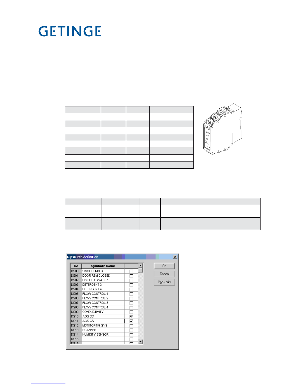
<Doc_TEC><Doc_502406700><Rel_B><Lang_GB>
Page 76 of 148
Connection AGS
AGS (Air Gliding System) is a transport system that automatically manages loading
and unloading of the washer disinfector. Communication between the transport system’s
PLC and the washer disinfector takes place via the AS-i bus.
Proceed as follows to connect the machine.
1. Connect the AS-i node (see the spare part list for the part no.) to terminal block –X11
in the electrical cabinet.
Terminal block Voltage Current Description
-X11:1 24VDC <200mA AS-i out 0
-X11:2 24VDC <200mA AS-i out 1
-X11:3 24VDC <200mA Voltage supply
-X11:4 24VDC <200mA AS-i I+
-X11:5 24VDC <200mA AS-i I1
-X11:6 24VDC <200mA AS-i I2
-X11:7 24VDC <200mA AS-i I3
-X11:8 24VDC <200mA Standby
See the wiring diagram for additional description of the connection points.
2. Connect the communication cable to terminal block –X07. See the wiring diagram for
additional description of the connection points.
Terminal block Voltage Current Description
-X11:9-12 Only for internal
communication
- Communication between the washer disinfector and AGS
-X07:15-18 Only for internal
communication
- Communication between the washer disinfector and AGS
See the wiring diagram for additional description of the connection points.
3. Set the dipswitches in the machine to permit communication with the AGS. The settings
for dipswitches are made in the service program, see Menu tree chapter 1.4.2.4
4. Set the address on the washer disinfector’s AS-i node. See the instruction in the manual
supplied with AGS.
J181
AS-i Node

Page 77 of 148
<Doc_TEC><Doc_502406700><Rel_B><Lang_GB>
Connection loader/unloader
Loader/unloader is a system that automatically manages loading and unloading of the
washer disinfector. The loader/unloaders can be one or two positions. Communication
between the loaders’ PLC and the washer disinfector takes place via a digital signal
transfer.
Proceed as follows to prepared the machine for the loaders.
1. Connect the cables for the loader in the machine between terminal block –X07 in the
electrical cabinet and connector –X261.
Terminal block Voltage Current Description
-X07:1
24VDC <500mA Voltage supply to the loader
-X07:2
-X07:3
-X07:7
24VDC <200mA Ready signal from the loader
-X07:8
-X07:11
24VDC <200mA Start signal to the loader
-X07:12
See the wiring diagram for additional description of the connection points.
2. Connect the cables for the unloader in the machine between terminal block –X07 in
the electrical cabinet and connector –X262.
Terminal block Voltage Current Description
-X07:4
24VDC <500mA Voltage supply to the unloader
-X07:5
-X07:6
-X07:9
24VDC <200mA Ready signal from the unloader
-X07:10
-X07:11
24VDC <200mA Start signal to the unloader
-X07:13
See the wiring diagram for additional description of the connection points
3. Connect the compressed air hoses between incoming compressed air connection and
each connection point on the loader/unloader.

<Doc_TEC><Doc_502406700><Rel_B><Lang_GB>
Page 78 of 148
4. Set the dipswitches in the machine to permit communication with each loader/unloader. The settings for dipswitches are made in the service program, see Menu tree
chapter 1.4.2.4
5. Follow the instruction supplied with the loader/unloaders to connect the loader with
the machine.
Loader
Unloader
J185
J188

Page 79 of 148
<Doc_TEC><Doc_502406700><Rel_B><Lang_GB>
Termination central dosing
The machine is prepared for connection to an external dosing system. Communication
between the washer disinfector and the central dosing system takes place via a digital
signal transfer.
The following signals are available for communication.
Terminal block Voltage Current Description
-X04:1-2 Potential free Max 1A Start signal dosing 1
-X04:3-4 Potential free Max 1A Start signal dosing 2
-X04:5-6 Potential free Max 1A Start signal dosing 3
-X04:7-8 Potential free Max 1A Start signal dosing 4
-X04:9 24VDC <200mA Common +24VDC (*)
-X04:10 24VDC <200mA Detergent dosing 1 available (*). (Signal from the central dosing system that the detergent is available)
-X04:11 24VDC <200mA Detergent dosing 2 available (*). (Signal from the central dosing system that the detergent is available)
-X04:12 24VDC <200mA Detergent dosing 3 available (*). (Signal from the central dosing system that the detergent is available)
-X04:13 24VDC <200mA Detergent dosing 4 available (*). (Signal from the central dosing system that the detergent is available)
-X06:9-10 24VDC <200mA Ext. Stop signal (*). E.g. incorrect dosing.
(*) The cable length must not exceed 10 m. The potential free contact must be used if necessary.

<Doc_TEC><Doc_502406700><Rel_B><Lang_GB>
Page 80 of 148
Potential free contacts
Themachineispreparedtosupplyspecicinformationtoanexternalsystem.Thereare
a number of potential free contacts on the machine for this purpose.
The following signals are available on the machine.
Terminal block Voltage Current Description
-X06:1-2 Potential free Max 1A Process running
-X06:3-4 Potential free Max 1A Process complete
-X06:5-6 Potential free Max 1A Alarms
-X06:7-8 Potential free Max 1A Forced ventilation
-X06:9-10 Potential free <200mA Ext. Stop signal (*). E.g. incorrect dosing.
(*) The cable length must not exceed 10 m. The potential free contact must be used if necessary.

Page 81 of 148
<Doc_TEC><Doc_502406700><Rel_B><Lang_GB>
Loading programs to flash memory
Theashmemory(existingornewcard)canbereloadedwithnewwashprogramsora
new system program. Loading new wash programs requires the CS-100/CS1000 program and loading of a new language version requires CSTools. Both can be purchased
via Getinge Academy. Instructions are supplied with CS-1000. System programs are
loaded with Flashloader.
Loading system programs
Note:
Always make a backup copy before starting work on updating system programs.
1. Connect a PC to the machine; see under Connecting a PC.
2. Check that the machine is in STANDBY mode.
3. Make a backup copy by starting CS 1000 and choosing:
Tools/PACS RAM/Upload To File...
4. Savethe*.prmleinyourchosenlocation.
5. If using existing card, do a Save RAM In Flash (the set calibration values will then
be automatically moved back after loading of the program(s))
6. Switch off the power to the machine with the main switch.
Figure 1
Figure 2

<Doc_TEC><Doc_502406700><Rel_B><Lang_GB>
Page 82 of 148
7. Move jumper 1 on the board for the PACS 350 control system from Normal to System
Load. Check that jumper 2 is in the Flash position and that jumper 3 is in the ON position.
8. Switch on the power to the machine with the main switch. The display lights up but
without text.
9. Start Flashloader from PC.
1
3
2

Page 83 of 148
<Doc_TEC><Doc_502406700><Rel_B><Lang_GB>
10. Set up as shown.
Filename Choose the right program file (*.a37).
Com Port The port to which you connected the data cable to your PC.
Baud Rate Choose 38400
All Sectors and Verbose must be checked (=selected).
11. Start loading by pressing Program !. The following image appears.
12. When loading is complete, the following image appears. Press OK.
Figure 6
Figure 7
Figure 8

<Doc_TEC><Doc_502406700><Rel_B><Lang_GB>
Page 84 of 148
13. Check that the battery jumper (3) is set to ON.
14. Switch off the power to the machine with the main switch.
15. Change the jumper (1) to Cold.
16. Switch on the power to the machine with the main switch. The display should
now show:
17. Without switching off the power, move jumper 1 to the Normal position.
18. Close Flashloader.
19. Start CS-1000 and load wash programs; see instructions for CS-1000.
Load language files
InstructionsforloadinglanguagelescomewiththeCS-1000package.
Note:
Always make a backup copy before starting work on updating system programs.
P00
Alternatively
P01 OP-SHORT-D
60.0°C 4
New card Existing card

Page 85 of 148
<Doc_TEC><Doc_502406700><Rel_B><Lang_GB>
Loading a new application into PACS
With CS1000
1. Makeabackupoftheexistingsoftware.“Tools”“PACSRAM”“Uploadtole
(if this has not already been done).
2. Download the new software. “Tools” “PACS RAM” “Download From File”.
Figure 1
Figure 3
3. Start the machine and check that everything is as it should be.
Figure 4

<Doc_TEC><Doc_502406700><Rel_B><Lang_GB>
Page 86 of 148
4. Switch off the power to the machine and install the “Flash prom” (if it is missing).
5. Switch on the power. Flash the new software to “Flash prom”. “Tools” “PACS
RAM” “Save RAM In Flash”. This may take a few seconds.
Flash prom
Reloading the backup from “flash prom” to PACS
Without CS1000
1. Switch off the power to the machine and remove the old prom with a prom extractor.
2. Move jumper 1 to cold start. Power on the machine and wait for a beep.
Now the display shows:
3. Switchoffthepowertothemachine.Installthenew“ashprom”.
4. Switchonthepower.Nowthenewsoftwarehasbeenloadedfromthe“ashprom”to the
processor.
5. Without switching off the power, move jumper 1 to the Normal position. Start the
machine and make sure that everything is working as it should.
P00
Flash prom
Figure 2
1

Page 87 of 148
<Doc_TEC><Doc_502406700><Rel_B><Lang_GB>
Cold start
Do a cold start when the machine has hung and you cannot proceed with the program.
1. Switch off the power to the machine.
2. Move the programming jumper (1) from Normal to Cold.
3. Switch on the power.
4. Move the programming jumper (1) from Coldstart to Normal. NOTE: The power is
still on.
5. Set the doors to the home position using the service program (tab 5 of the Software
description and settings, section headed Test digital output display (1.4.2.5.3.4) or
CS1000.
Home position for the doors:
Soiled side = door unlocked and open
Clean side = door closed and locked
1

<Doc_TEC><Doc_502406700><Rel_B><Lang_GB>
Page 88 of 148
Changing user language
The language can be changed in two ways, via the control panel or via CS1000.
With user panel
The user language can be changed in the “Settings”“Systemmenu”“Conguration”
“Language Date format” menu. See menu tree in this manual.
With CS1000
Theuserpanellanguagecanbechangedinthe“System”“Systemconguration”menu.
Figure 5

Page 89 of 148
<Doc_TEC><Doc_502406700><Rel_B><Lang_GB>
Calibration
Calibrating PACS conductivity
To calibrate the conductivity meter, proceed as follows.
1. Connect a PC with the CS 1000 program installed to the disinfector.
2. Press [ on the conductivity meter.
3. Enter code 22 with Y and Z.
4. Press [. Setup 1 appears.
5. Choose Output med Y and Z.
6. Press [. Sel. Type appears.
7. Choose SIM med Y and Z.
8. Press [ .
9. Choose 0 ... with Y and Z 22 mA.
10. Set 4 mA.
11. Start CS 1000 and choose Settings/Calibration/Analog Input Automatic...
V1563
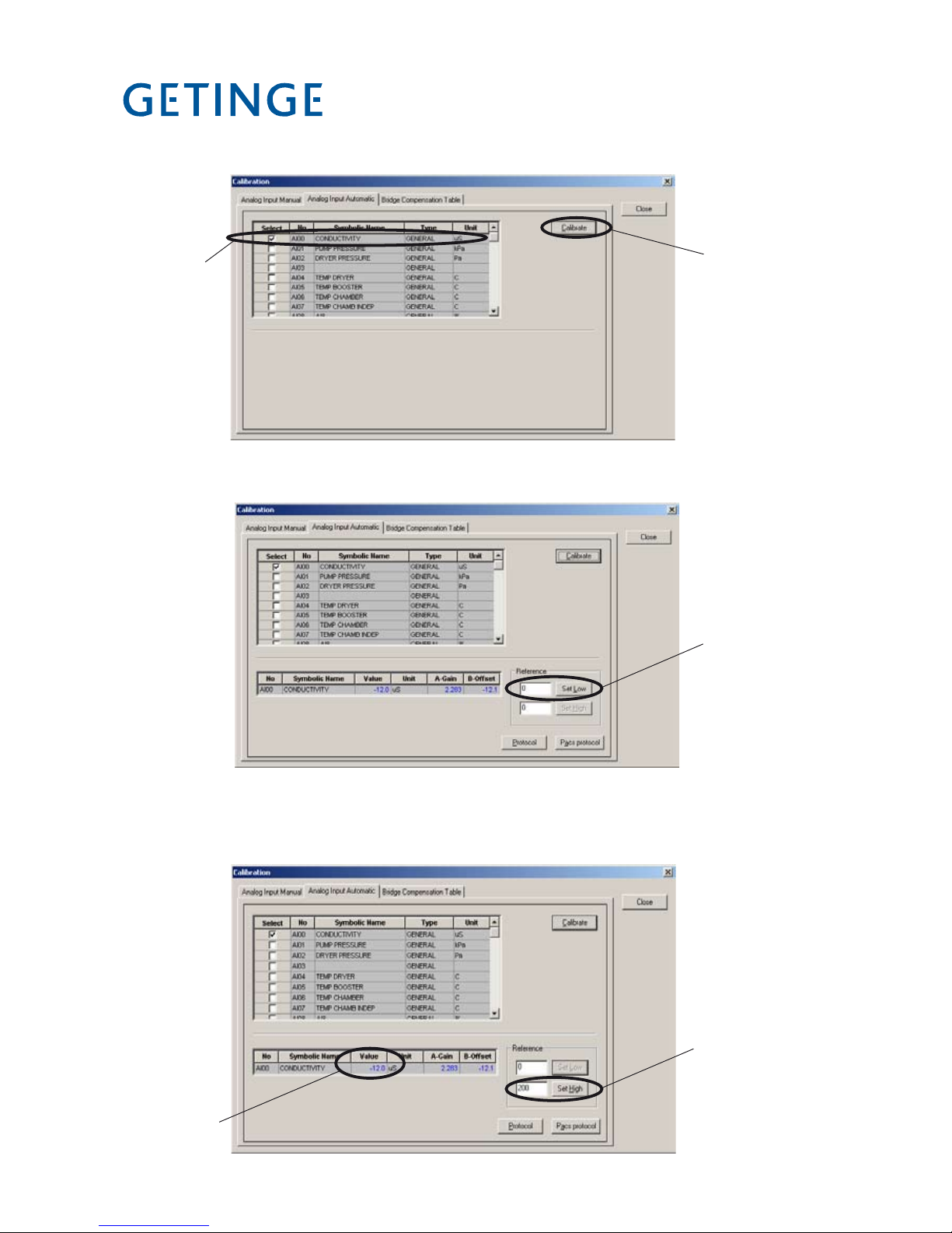
<Doc_TEC><Doc_502406700><Rel_B><Lang_GB>
Page 90 of 148
12. Click Conductivity (A) and then Calibrate (B).
13. Enter the value 0 (C) and click Set Low.
A
B
C
V1564
V1565
D
E
V1566
14. Set 20 mA on the conductivity meter with Y and Z.
15. Enter 500 (D) in CS 1000 and click Set High.

Page 91 of 148
<Doc_TEC><Doc_502406700><Rel_B><Lang_GB>
16. Check that the value (E) rises to 500.
17. Cancel the acoustic signal by pressing Close (F).
18. Press Y and Z at the same time. Output appears on the display.
19. Press [. Sel. Type appears.
20. Choose Lin. with Z.
21. Press [ .
22. Press Y and Z at the same time twice to log out of the conductivity meter.
F
V1566

<Doc_TEC><Doc_502406700><Rel_B><Lang_GB>
Page 92 of 148
Pressure sensor for circulation pump
To calibrate the pressure sensor for the circulation pump, proceed as follows.
1. Connect a PC with the CS 1000 program installed to the disinfector.
2. Connect a process simulator to A01-X1;
+ on 3B
- on 3A
3. Set the process simulator to 4 mA.
4. Start CS 1000 and choose Settings/Calibration/Analog Input Automatic...
5. Click Pump pressure (A) and then Calibrate (B).
V1563
V1567
A
B

Page 93 of 148
<Doc_TEC><Doc_502406700><Rel_B><Lang_GB>
6. Enter the value 0 (C) and click Set Low.
7. Set the process simulator to 20 mA.
8. Enter 160 (D) in CS 1000 and click Set High.
9. Check that the value (E) rises to 160.
10. Log off CS 1000.
V1569
V1568
C
D
E

<Doc_TEC><Doc_502406700><Rel_B><Lang_GB>
Page 94 of 148
Temperature sensors - with resistor
Proceed as follows to calibrate the temperature sensors with the aid of resistors:
1. Connect a PC with the CS 1000 program installed to the disinfector.
2. Insert resistors for 20 ºC at the following places:
A01-X1 Chamber temperature 9A, 10A
A01-X2 Independent chamber temperature 5A, 6A
A01-X2 Booster tank 3A, 4A
A01-X5 Dryer 1A, 2A
3. Start CS 1000 and choose Settings/Calibration/Analog Input Automatic...
4. Click Temp booster, Temp chamber and Temp chamb indep (A), then click
Calibrate (B).
V1570
V1563
A
B

Page 95 of 148
<Doc_TEC><Doc_502406700><Rel_B><Lang_GB>
5. Enter the value 20 (C) and click Set Low.
6. Check that the value (D) rises to 20.
7. Replace resistors for 20 ºC with resistors for 90 ºC.
8. Enter 90 (E) in CS 1000 and click Set High.
9. Check that the value (F) rises to 90.
10. Log off CS 1000.
11. Remove the resistors and reinstate the temperature sensors.
V1572
V1571
C
E
F
D

<Doc_TEC><Doc_502406700><Rel_B><Lang_GB>
Page 96 of 148
Temperature sensor - with ice bath and oil bath
Proceed as follows to calibrate the temperature sensors with the aid of an ice bath and an oil bath:
1. Connect a PC with the CS 1000 program installed to the disinfector.
2. Prepare an ice bath and an oil bath.
The ice bath must consist of crushed ice in a bowl of cold water. The bath must stand
for at least 20 minutes so that the temperature can stabilize.
The oil bath must be switched on for at least 45 minutes at the set temperature
(100 ºC) to stabilize the temperature.
3. Remove the temperature sensors from the disinfector. Tape the sensors together.
4. Lower the temperature sensors into the ice bath together with an external thermometer.
5. Start CS 1000 and choose Settings/Calibration/Analog Input Automatic...
6. Click Temp booster, Temp chamber and Temp chamb indep (A), then click
Calibrate (B).
V1563
V1571
A
B

Page 97 of 148
<Doc_TEC><Doc_502406700><Rel_B><Lang_GB>
7. Check that the reading of the external thermometer stabilizes. Enter the reading of
the external thermometer (C) and click Set Low.
8. Check that the value (D) rises to the set value.
9. Move the temperature sensors and the external thermometer to the oil bath. Check
that the reading of the external thermometer stabilizes. Enter the reading of the external thermometer (E) and click Set High.
10. Check that the value (F) rises to the set value.
11. Log off CS 1000.
12. Re-instate the temperature sensors.
V1572
V1571
C
E
F
D

<Doc_TEC><Doc_502406700><Rel_B><Lang_GB>
Page 98 of 148
Differential pressure gauge for dryer
To calibrate the differential pressure gauge for the dryer, proceed as follows.
1. Connect a PC with the CS 1000 program installed to the disinfector.
2. Close the machine doors.
3. Connect an external differential pressure gauge in parallel with the existing gauge on
the machine. Zero the external differential pressure gauge.
4. Start CS 1000 and choose Settings/Calibration/Analog Input Automatic...
5. Click Dryer pressure (A) and then Calibrate (B).
V1573
V1563
A
B

Page 99 of 148
<Doc_TEC><Doc_502406700><Rel_B><Lang_GB>
6. Enter the value 0 (C) and click Set Low.
7. Start the machine fan manually as follows:
Scroll to SETUP with J. Press S.
Scroll to SYSTEM with J. Press S.
Enter password. Press S.
Scroll to SERVICE with J. Press S.
Scroll to DIAGNOSTICS with J. Press S.
Scroll to TEST ANALOG OUT with J. Press S.
>SETUP
>SYSTEM
APPLIANCE INFO
>ENTER PASSWORD
>SERVICE
SAVE RAM IN FLASH
SERVICE MESSAGE
>DIAGNOSTICS
>TEST ANALOG OUT
TEST DIGITAL IN
V1574
C

<Doc_TEC><Doc_502406700><Rel_B><Lang_GB>
Page 100 of 148
Scroll to 01 FAN SPEED DRYER with J. Press S.
Change AUT to MAN with K. Set fan speed to 100 %.
8. Check the reading of the external differential pressure gauge. Enter the reading of
gauge (D) in CS 1000 and click Set High.
The reading should be between 200 and 400 Pa.
Ifitistoohigh,theltermaybeclogged;ifitistoolow,theremaybeaholeinthelter.
9. Check that the value (E) rises to the reading of the external differential pressure gauge.
10. Log off CS 1000.
11. Reinstate the fan.
Set fan speed to 0 %. Change MAN to AUT with K.
Press S.
12. Log out.
13. Reinstate the differential pressure gauge.
>01 FAN SPEED DRYER
AUT 100%
>01 FAN SPEED DRYER
MAN 100%
>01 FAN SPEED DRYER
MAN 0%
V1574
D
E
 Loading...