


600 SERIES STEAM STERILIZERS
INSTALLATION MANUAL
61301607027 REV A US

INSTALLATION MANUAL
61301607027 REV A US
12/21/07
Getinge®, Biosign®, and EZ-VU® are registered trademarks.
Copyright ©2007 Getinge USA, Inc.
PUBLICATION HISTORY
Revision Date Reason
A
For quality service on the equipment and information on our Performance
Assurance Plan, contact:
Getinge USA, Inc.
1777 East Henrietta Road
Rochester, NY 14623-3133
Phone: 1-800-950-9912
www.getingeproducts.com
NOTE
This manual contains proprietary information of Getinge USA, Inc. It shall
not be reproduced in whole or in part without the written permission of
Getinge USA, Inc.
This manual is intended for qualified technicians with specialized training. If
you require additional help, contact the company service representative.
WARNING
POSSIBILITY OF INJURY: Misuse of equipment or bypassing its safety
features may result in personal injury.
12/2007 Initial Release
CAUTION
POSSIBILITY OF EQUIPMENT DAMAGE: Misuse of equipment may result
in equipment damage.
The 600 Series Steam Sterilizer is designed to steam sterilize hospital and
laboratory goods and solutions. This equipment is NOT intended for use
other than expressly stated.
ii INS 61301607027 Rev A US

SECTION 1 PREFACE
600 Series Steam Sterilizers
TABLE OF CONTENTS
Before You Begin . . . . . . . . . . . . . . . . . . . . . . . . . . . . . . . . . . . . . . . . . .1–1
Summary of Contents . . . . . . . . . . . . . . . . . . . . . . . . . . . . . . . . . . . . . . .1–2
Environmental Impact Assessment. . . . . . . . . . . . . . . . . . . . . . . . . . . . .1–2
Description of Symbols on the Equipment . . . . . . . . . . . . . . . . . . . . . . .1–3
Switches . . . . . . . . . . . . . . . . . . . . . . . . . . . . . . . . . . . . . . . . . . . . . .1–3
Indicators . . . . . . . . . . . . . . . . . . . . . . . . . . . . . . . . . . . . . . . . . . . . .1–4
Labels . . . . . . . . . . . . . . . . . . . . . . . . . . . . . . . . . . . . . . . . . . . . . . . .1–4
Manual Conventions . . . . . . . . . . . . . . . . . . . . . . . . . . . . . . . . . . . . . . . . 1–5
Symbols Used in This Manual. . . . . . . . . . . . . . . . . . . . . . . . . . . . . . . . .1–5
SECTION 2 SAFETY
SECTION 3 PACKAGING
How to Use This Manual . . . . . . . . . . . . . . . . . . . . . . . . . . . . . . . . . . . . .1–6
Plan the Installation . . . . . . . . . . . . . . . . . . . . . . . . . . . . . . . . . . . . . 1–6
Install the Equipment . . . . . . . . . . . . . . . . . . . . . . . . . . . . . . . . . . . .1–6
General . . . . . . . . . . . . . . . . . . . . . . . . . . . . . . . . . . . . . . . . . . . . . . . . . . 2–1
Safety Features . . . . . . . . . . . . . . . . . . . . . . . . . . . . . . . . . . . . . . . . . . . .2–3
Door Lockout . . . . . . . . . . . . . . . . . . . . . . . . . . . . . . . . . . . . . . . . . .2–3
Door Obstruction Switch . . . . . . . . . . . . . . . . . . . . . . . . . . . . . . . . .2–3
Isolating Device . . . . . . . . . . . . . . . . . . . . . . . . . . . . . . . . . . . . . . . . . . . .2–4
Product Liability . . . . . . . . . . . . . . . . . . . . . . . . . . . . . . . . . . . . . . . . . . .2–5
Before You Begin . . . . . . . . . . . . . . . . . . . . . . . . . . . . . . . . . . . . . . . . . .3–1
Uncrating. . . . . . . . . . . . . . . . . . . . . . . . . . . . . . . . . . . . . . . . . . . . . . . . .3–2
Unpacking the Sterilizer . . . . . . . . . . . . . . . . . . . . . . . . . . . . . . . . . .3–2
Removing the Sterilizer Front Panels . . . . . . . . . . . . . . . . . . . . . . . .3–4
Removing the Skid . . . . . . . . . . . . . . . . . . . . . . . . . . . . . . . . . . . . . .3–5
SECTION 4 INSTALLATION INSTRUCTIONS
Before You Begin . . . . . . . . . . . . . . . . . . . . . . . . . . . . . . . . . . . . . . . . . .4–1
INS 61301607027 Rev A US iii

Table of Contents
Utility Requirements . . . . . . . . . . . . . . . . . . . . . . . . . . . . . . . . . . . . 4–1
Tools and Materials Required . . . . . . . . . . . . . . . . . . . . . . . . . . . . . 4–2
Positioning and Leveling . . . . . . . . . . . . . . . . . . . . . . . . . . . . . . . . . . . . 4–3
Positioning the Sterilizer . . . . . . . . . . . . . . . . . . . . . . . . . . . . . . . . . 4–5
Leveling the Sterilizer Chamber . . . . . . . . . . . . . . . . . . . . . . . . . . . 4–9
Leveling the Sterilizer Door . . . . . . . . . . . . . . . . . . . . . . . . . . . . . . 4–13
Installing the Kick Panel . . . . . . . . . . . . . . . . . . . . . . . . . . . . . . . . 4–17
Re-attaching the Front Panels . . . . . . . . . . . . . . . . . . . . . . . . . . . 4–18
Utility Requirements . . . . . . . . . . . . . . . . . . . . . . . . . . . . . . . . . . . . . . 4–19
Connecting the Plumbing . . . . . . . . . . . . . . . . . . . . . . . . . . . . . . . . . . 4–20
Sterilizer Connections . . . . . . . . . . . . . . . . . . . . . . . . . . . . . . . . . . 4–20
Booster Pump (Option) . . . . . . . . . . . . . . . . . . . . . . . . . . . . . . . . . 4–20
Steam Boiler (Option) . . . . . . . . . . . . . . . . . . . . . . . . . . . . . . . . . . 4–21
Connecting the Electrical Power . . . . . . . . . . . . . . . . . . . . . . . . . . . . . 4–22
Electrical Supply Requirements . . . . . . . . . . . . . . . . . . . . . . . . . . 4–22
Connecting the Customer Supply. . . . . . . . . . . . . . . . . . . . . . . . . 4–23
Steam Boiler (Option) . . . . . . . . . . . . . . . . . . . . . . . . . . . . . . . . . . 4–25
Booster Pump (Option) . . . . . . . . . . . . . . . . . . . . . . . . . . . . . . . . . 4–25
Anchoring the Sterilizer . . . . . . . . . . . . . . . . . . . . . . . . . . . . . . . . . . . . 4–26
Installing the Hold-Down Brackets . . . . . . . . . . . . . . . . . . . . . . . . 4–26
Installing the Seismic Anchoring Brackets . . . . . . . . . . . . . . . . . . 4–28
Installing the Interior Equipment . . . . . . . . . . . . . . . . . . . . . . . . . . . . . 4–31
Installing the Rack and Shelves . . . . . . . . . . . . . . . . . . . . . . . . . . 4–31
Installing the Loading Car Track . . . . . . . . . . . . . . . . . . . . . . . . . . 4–32
SECTION 5 OPTIONAL EQUIPMENT
Introduction . . . . . . . . . . . . . . . . . . . . . . . . . . . . . . . . . . . . . . . . . . . . . . 5–1
Steam Boiler . . . . . . . . . . . . . . . . . . . . . . . . . . . . . . . . . . . . . . . . . . . . . 5–2
Specifications . . . . . . . . . . . . . . . . . . . . . . . . . . . . . . . . . . . . . . . . . 5–2
Boiler Models . . . . . . . . . . . . . . . . . . . . . . . . . . . . . . . . . . . . . . . . . 5–2
Connecting the Plumbing . . . . . . . . . . . . . . . . . . . . . . . . . . . . . . . . 5–2
Connecting the Electrical Power. . . . . . . . . . . . . . . . . . . . . . . . . . . 5–4
Checking the Heater Circuit Connections . . . . . . . . . . . . . . . . . . . 5–6
Booster Pump Package . . . . . . . . . . . . . . . . . . . . . . . . . . . . . . . . . . . . 5–9
Typical Installation. . . . . . . . . . . . . . . . . . . . . . . . . . . . . . . . . . . . . . 5–9
Mounting the Booster Pump and Interface Box . . . . . . . . . . . . . . 5–12
Connecting the Plumbing . . . . . . . . . . . . . . . . . . . . . . . . . . . . . . . 5–13
Connecting the Electrical Power. . . . . . . . . . . . . . . . . . . . . . . . . . 5–14
iv INS 61301607027 Rev A US

600 Series Steam Sterilizers
Universal Transformer . . . . . . . . . . . . . . . . . . . . . . . . . . . . . . . . . . . . . .5–16
Connecting the Transformer. . . . . . . . . . . . . . . . . . . . . . . . . . . . . .5–17
Uninterruptible Power Supply (UPS) . . . . . . . . . . . . . . . . . . . . . . . . . . .5–18
Unpacking . . . . . . . . . . . . . . . . . . . . . . . . . . . . . . . . . . . . . . . . . . .5–19
Mounting. . . . . . . . . . . . . . . . . . . . . . . . . . . . . . . . . . . . . . . . . . . . .5–19
Connecting the Electrical Power . . . . . . . . . . . . . . . . . . . . . . . . . .5–20
Water-Saver System . . . . . . . . . . . . . . . . . . . . . . . . . . . . . . . . . . . . . . .5–22
Water Treatment System. . . . . . . . . . . . . . . . . . . . . . . . . . . . . . . . . . . .5–25
Cabinet Package. . . . . . . . . . . . . . . . . . . . . . . . . . . . . . . . . . . . . . . . . .5–26
Unpacking . . . . . . . . . . . . . . . . . . . . . . . . . . . . . . . . . . . . . . . . . . .5–27
Preparing the Side Panels . . . . . . . . . . . . . . . . . . . . . . . . . . . . . . .5–29
Installing the Support Brackets . . . . . . . . . . . . . . . . . . . . . . . . . . .5–30
Hanging the Panels . . . . . . . . . . . . . . . . . . . . . . . . . . . . . . . . . . . .5–32
SECTION 6 DRAWINGS
List of Drawings . . . . . . . . . . . . . . . . . . . . . . . . . . . . . . . . . . . . . . . . . . .6–1
Installation Drawings . . . . . . . . . . . . . . . . . . . . . . . . . . . . . . . . . . . . . . . .6–1
SECTION 7 TECHNICAL DATA
Introduction . . . . . . . . . . . . . . . . . . . . . . . . . . . . . . . . . . . . . . . . . . . . . . .7–1
Sterilizer Dimensions. . . . . . . . . . . . . . . . . . . . . . . . . . . . . . . . . . . . . . . .7–2
Interior Dimensions. . . . . . . . . . . . . . . . . . . . . . . . . . . . . . . . . . . . . .7–2
Exterior Dimensions (with Cabinet Package) . . . . . . . . . . . . . . . . . .7–2
Steam Supply Quality . . . . . . . . . . . . . . . . . . . . . . . . . . . . . . . . . . . . . . .7–3
Steam Boiler Feedwater Quality . . . . . . . . . . . . . . . . . . . . . . . . . . . . . . .7–5
SECTION 8 FUNCTIONAL CHECK
Installation Check . . . . . . . . . . . . . . . . . . . . . . . . . . . . . . . . . . . . . . . . . .8–1
Inspection by Installers . . . . . . . . . . . . . . . . . . . . . . . . . . . . . . . . . . .8–1
Final Inspection by Getinge . . . . . . . . . . . . . . . . . . . . . . . . . . . . . . .8–1
Validation by Customer . . . . . . . . . . . . . . . . . . . . . . . . . . . . . . . . . .8–1
INDEX
INS 61301607027 Rev A US v

Table of Contents
vi INS 61301607027 Rev A US

BEFORE YOU BEGIN
SECTION 1 PREFACE
Before installing the sterilizer, please read all the instructions and become
familiar with the sterilizer’s design, safety features, and operation.
This manual is intended to provide the knowledge to ensure safe sterilizer
installation by qualified technicians with specialized training in the
installation of Getinge 600 Series Sterilizers. If additional help is required,
contact a qualified Getinge service representative.
The following documentation is supplied with the machine:
• User Manual, Part Number 61301607026 (633HC) or 61301607502
(633LS)
• Installation Manual, Part Number 61301607027
• Quick Reference Poster, Part Number 61301607268 (633HC) or
61301607503 (633LS)
The following documentation is available for purchase:
• Technical Manual, Part Number 61301607028
• Parts Catalog, Part Number 61301607029
NOTE
Getinge reserves the right to make changes to specifications and
equipment without prior notice. The information contained within this
manual is current as of the date of issue.
INS 61301607027 Rev A US 1–1

Preface
SUMMARY OF CONTENTS
This manual is divided into eight (8) sections as follows:
• Section 1 Preface—includes information regarding the intended
audience, a summary of the manual’s contents, advisories, and
environmental impact.
• Section 2 Safety—includes important precautions and safety features.
• Section 3 Packaging—includes information regarding the uncrating
and positioning of the sterilizer.
• Section 4 Installation Instructions—includes information regarding the
assembly and connection of the sterilizer, as well as plumbing and
electrical information.
• Section 5 Optional Equipment—includes information and drawings for
all available sterilizer options.
• Section 6 Drawings—includes Roughing-In Drawings, and Seismic
Anchorage Calculations.
• Section 7 Technical Data—includes product requirements and
specifications.
• Section 8 Functional Check—includes a checklist to verify the
operational state of the sterilizer after installation.
ENVIRONMENTAL IMPACT ASSESSMENT
The 600 Series Steam Sterilizers consist of stainless steel, copper, and
electronic and electrical components which can be recycled at the end of
the sterilizer lifecycle. The sterilizer also contains plastic and batteries
which can NOT be recycled and should be disposed of in accordance with
local and federal regulations.
1–2 INS 61301607027 Rev A US
DESCRIPTION OF SYMBOLS ON THE EQUIPMENT
!
CONTROLS
DISABLE ENABLE
WS-0243
The following symbols and definitions represent the switches, indicators,
and labels found on the unit.
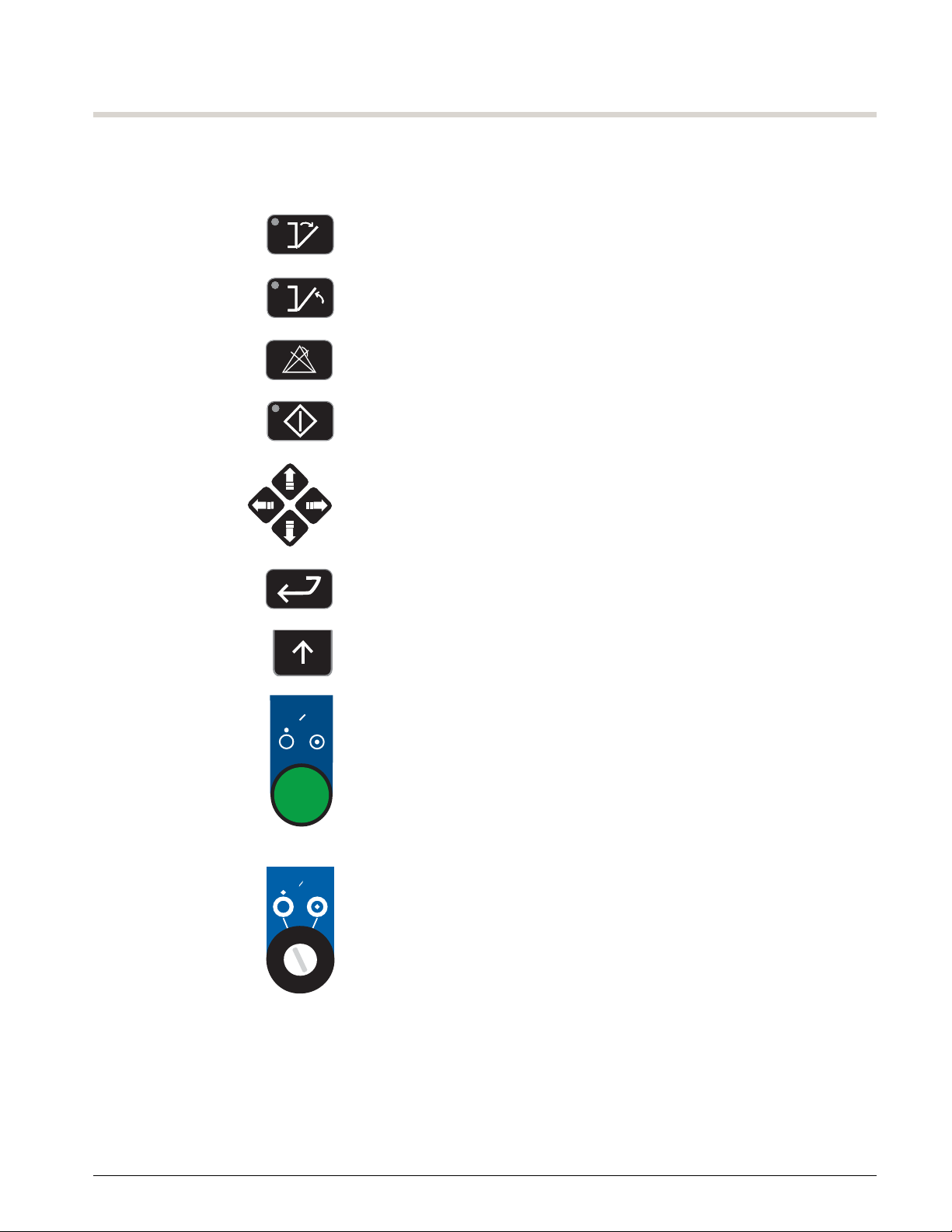
SWITCHES Open Door
Close Door
Clear Alarm
Start
Directional Arrows (for navigating display screens)
600 Series Steam Sterilizers
CONTROLS
OFF ON
WS-0091
Enter
Up Arrow Softkeys (for selecting softkey options (i.e. Save, Cancel, or OK))
CONTROLS OFF/ON
CONTROLS DISABLE/ENABLE
INS 61301607027 Rev A US 1–3
Preface
!
HS
Contact Getinge USA Customer Support (800) 950-9912
If water leaks from the front of the sterilizer,
DO NOT open the door (see User Manual)
Steam released from the sterilizer chamber can
cause serious burns
Stand away while opening the door
WARNING — BURN HAZARD
MGA
61301607429 REV A
PROCESSING A TYPE OF LOAD OTHER
THAN DEFINED IN USER
MANUAL COULD BE HAZARDOUS
OBSERVE PRECAUTIONS
FOR HANDLING
SENSITIVE
DEVICES
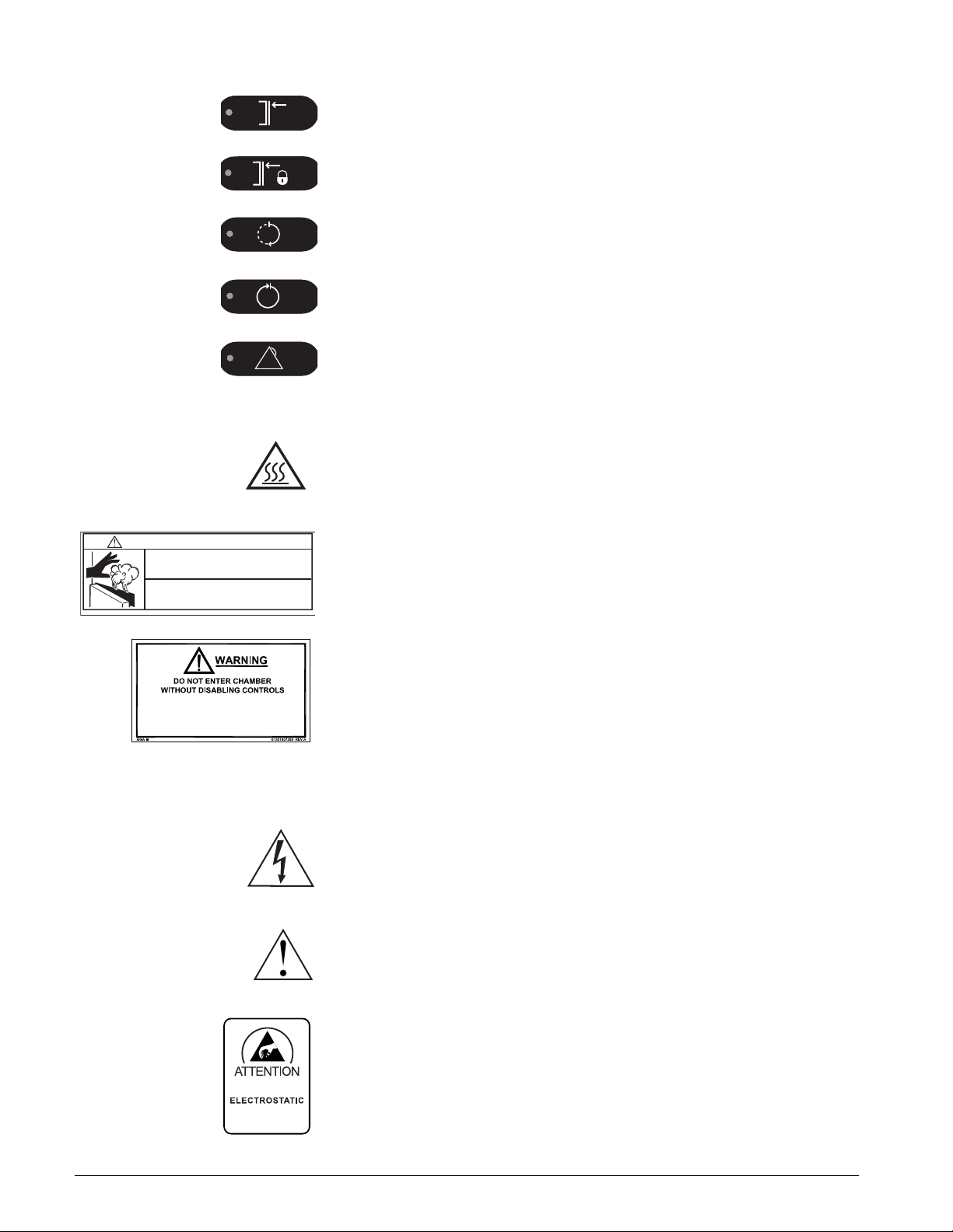
INDICATORS Door(s) Closed
Door(s) Sealed
In Process
Process Complete
Process Failure
LABELS The following labels on the sterilizer alert personnel to possible hazards.
Hot surfaces or heat-emitting area. Avoid contact. Risk of burns.
WARNING—BURN HAZARD: Steam released from the sterilizer chamber
can cause serious burns. Stand away when opening door.
WARNING: Do not enter chamber without disabling controls. Processing a
type of load other than defined in the User Manual could be hazardous.
The following labels on the Control Box and Power Box alert service
personnel to possible hazards.
HIGH VOLTAGE
CAUTION: To reduce the risk of electrical shock, do not remove cover.
Refer servicing to qualified service personnel.
ATTENTION: Refer to accompanying documents for further information.
1–4 INS 61301607027 Rev A US
Electrostatic Sensitive Devices
MANUAL CONVENTIONS
600 Series Steam Sterilizers
Before you begin using this manual, it is important to understand the
conventions used. These conventions are established for visual ease of
use.
ITALIC CAPS Display text, such as the ENTER
PASSWORD prompt.
[ALL CAPS] Softkeys on the control panel, such as
[CANCEL] or [OK].
ALL CAPS Switches and indicators on the control panel,
such as ENTER.
> The > symbol leads you through nested
menu items and dialog box options to a final
action. For example: PARAMETERS>enter
password>EDIT.
Italic Upper/Lower Case Cross reference to another manual or guide,
such as: see “Leveling the Sterilizer Door” on
page 4–13.
SYMBOLS USED IN THIS MANUAL
The following symbols with related notes appear in this manual.
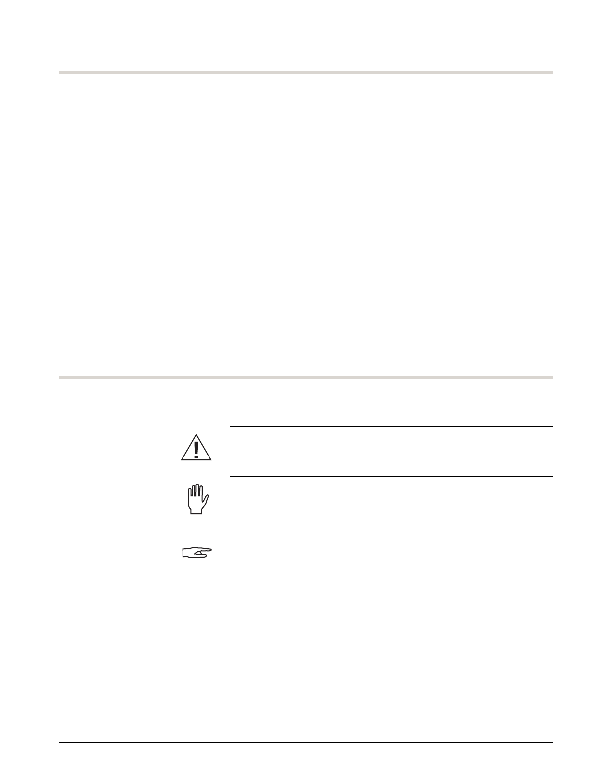
WARNING
“Warning” notes alert the user to the possibility of personal injury.
CAUTION
“Caution” notes alert the user to the possibility of damage to the
equipment.
NOTE
“Notes” alert the user to pertinent facts and conditions.
INS 61301607027 Rev A US 1–5

Preface
HOW TO USE THIS MANUAL
PLAN THE INSTALLATION Ensure all installation requirements have been met:
1. Review the Installation Drawings (Section 6) and architect’s drawing.
2. Review the Technical Data (Section 7) for steam supply and steam
boiler feedwater quality recommendations.
INSTALL THE EQUIPMENT Install the sterilizer as follows:
1. Unpack the sterilizer.
2. Remove the sterilizer from the skid, then roll the sterilizer to the room
where it will be located.
3. Position and level the sterilizer.
4. Connect the plumbing.
5. Connect the wiring.
6. Install any remaining optional equipment.
7. Anchor the sterilizer.
8. Install the optional cabinet package.
9. Perform the functional check.
1–6 INS 61301607027 Rev A US

GENERAL
SECTION 2 SAFETY
The 600 Series Steam Sterilizers are designed to sterilizer and dry (where
applicable) typical healthcare and laboratory goods. The sterilizers will
include pressure pulse gravity steam, pressure vacuum pulsing, and liquids
cycles. These sterilizers are NOT intended for use other than expressly
stated.
The sterilizers are designed with a number of built-in safety devices. To
avoid injury, it is very important that these safety devices are not bypassed
and/or disabled.
CAUTION
DAMAGE TO EQUIPMENT: Follow the instructions in this manual to ensure
the safe and efficient performance of the sterilizer. Failure to comply with
these instructions or to provide specific services could void the warranty.
AUTHORIZED SERVICE REPRESENTATIVE
• Read all instructions thoroughly before installation.
• Installation and service work must be performed by qualified personnel
trained on this sterilizer.
• The sterilizer must be operated by personnel who are knowledgeable
about the sterilizer operation and are trained on its use.
• Personnel must receive regular periodic training on the operation and
maintenance of this equipment in accordance with established
procedures for the workplace.
ELECTRICAL SAFETY
• Switch off the electric power before opening the electrical components.
The components contain the following voltage:
Control Box 24 Vac
Power Box 115 Vac
Boilers 208, 240, 480, or 600 Vac, Three-Phase
• Before welding begins on or close to the sterilizer, all wiring connected
by plugs and sockets must be disconnected from all circuit boards of
the control system.
INS 61301607027 Rev A US 2–1

Safety
HOT SURFACES AND PIPES
WARNING
BURN HAZARD: Turn OFF and lock out/tag out the steam and hot water
supplies before servicing the sterilizer. Allow the steam to dissipate and let
the sterilizer cool down before touching any piping or surfaces.
• There are hot surfaces in the service area. Avoid touching any piping
that could contain steam.
• The sterilizer uses hot water and steam which have the potential of
causing burns or serious injuries. Wear personal protective equipment
suitable for hot water and steam.
LOCKOUT
• Always keep the door to the service area locked.
• No personnel should be in the service area while the sterilizer is
running.
• Never bypass the door limit switches of the sterilizer.
• When servicing the unit, the CONTROLS DISABLE/ENABLE switch
should be set to DISABLE. Remove the key and keep it with you.
OTHER CONSIDERATIONS
• Leakage in the system must be repaired without delay.
• The sterilizer must be kept clean to ensure optimum performance.
• Do not hose down the outside of the sterilizer with water.
2–2 INS 61301607027 Rev A US
600 Series Steam Sterilizers
WS-0421
Top of Door Light Beam
Door Obstruction Switch
SAFETY FEATURES
WARNING
SHOCK HAZARD: To disconnect all power, turn OFF the sterilizer at the
mains circuit breaker. The On/Off Controls do not remove primary power
from the sterilizer.
NOTE
The maximum sound pressure level of the equipment that the operator is
exposed to does not exceed 85 dBA
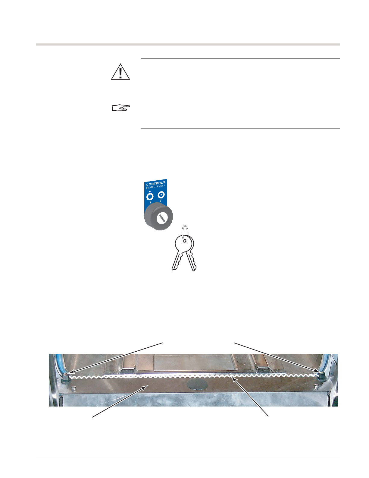
DOOR LOCKOUT The door can be locked in the open position for maintenance when inside
the chamber. Turn the key to DISABLE and remove it. To prevent someone
from closing the door during maintenance, keep the keys with you.
FIGURE 2–1. LOCKING THE DOOR IN THE OPEN POSITION
WS-0420
DOOR OBSTRUCTION SWITCH The sterilizer uses a light beam switch at the top of the door to sense when
an object is in the path of the movement of the door. When the light beam
is broken as the door is closing, the door stops and reverses for two
seconds.
FIGURE 2–2. DOOR OBSTRUCTION SWITCH
INS 61301607027 Rev A US 2–3
Safety
A07027-K
Power Box Main Switch
Steam Boiler
(option)
Mains
Disconnect
Breaker
Heater Voltage
(208/240/480/600 Vac
Three-Phase)
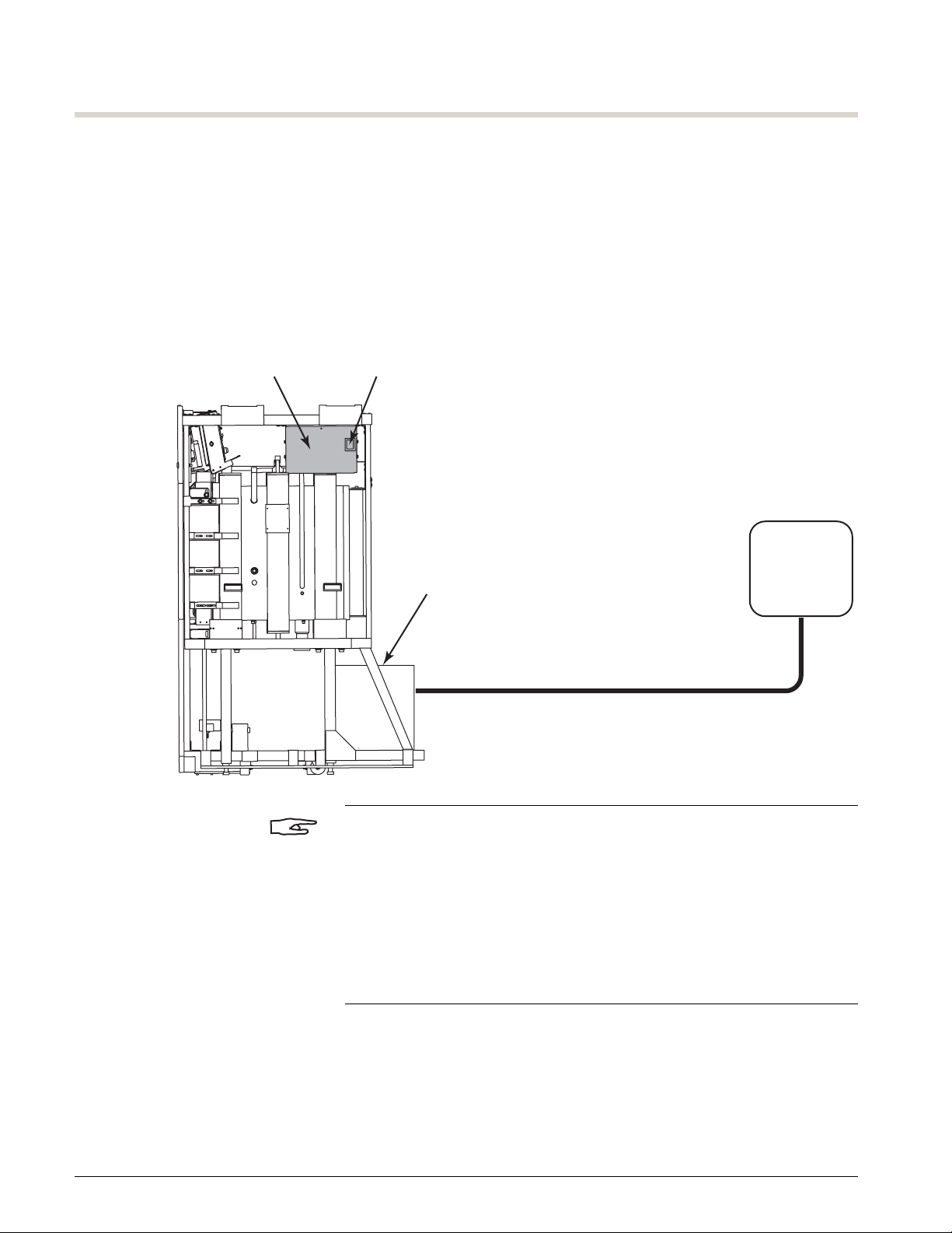
ISOLATING DEVICE
The sterilizer is fitted with a main switch on the power box (located on the
right side of the sterilizer). This switch removes primary power (120 Vac)
from the sterilizer.
Sterilizers with a steam boiler have a three-phase heating circuit that
requires a separate mains disconnect. The power switch on the boiler turns
the boiler control circuits ON and OFF.
FIGURE 2–3. CIRCUIT BREAKER LOCATION
NOTE
The CONTROLS ON/OFF switch turns the sterilizer controls ON and OFF
but does not remove primary power.
The CONTROLS DISABLE/ENABLE switch disables the door motor circuits
to prevent door movement during routine maintenance.
The control voltage for the optional steam boiler is provided by the sterilizer
power box.
2–4 INS 61301607027 Rev A US

PRODUCT LIABILITY
600 Series Steam Sterilizers
Modifications made to the sterilizer without the express approval of the
manufacturer, or incorrect use of the unit will invalidate the manufacturer’s
product liability.
INS 61301607027 Rev A US 2–5

Safety
2–6 INS 61301607027 Rev A US

BEFORE YOU BEGIN
SECTION 3 PACKAGING
The Getinge 600 Series Sterilizers are shipped fully assembled. Only
qualified Getinge service representatives or personnel trained by Getinge
should install the sterilizer.
WARNING
POSSIBILITY OF INJURY: The sterilizer is top-heavy and could tip when
you remove it from the shipping base.
Use caution when moving the unit to ensure there is no accidental tipping
causing damage or bodily injury.
SHIPPING WEIGHT
Refer to the following chart for the weight of the crated sterilizers:
Chamber Length 26 in. 39 in. 51 in.
Single Door 1,160 lb
(526 kg)
Double Door N/A 1,508 lb
LIFTING EQUIPMENT
A pallet jack is required to remove the sterilizer from its shipping skid. Once
the skid is removed, the sterilizer can be rolled on its casters to the room
where it will be located.
CLEARANCES
The uncrated sterilizer is 39.5 inches (1003 mm) wide and 73.5 inches (1867
mm) tall. The maximum length of the sterilizer is 65.75 inches (1670 mm).
1,365 lb
(619 kg)
(684 kg)
1,506 lb
(683 kg)
1,649 lb
(748 kg)
INS 61301607027 Rev A US 3–1
Packaging
A00294-D
UNCRATING
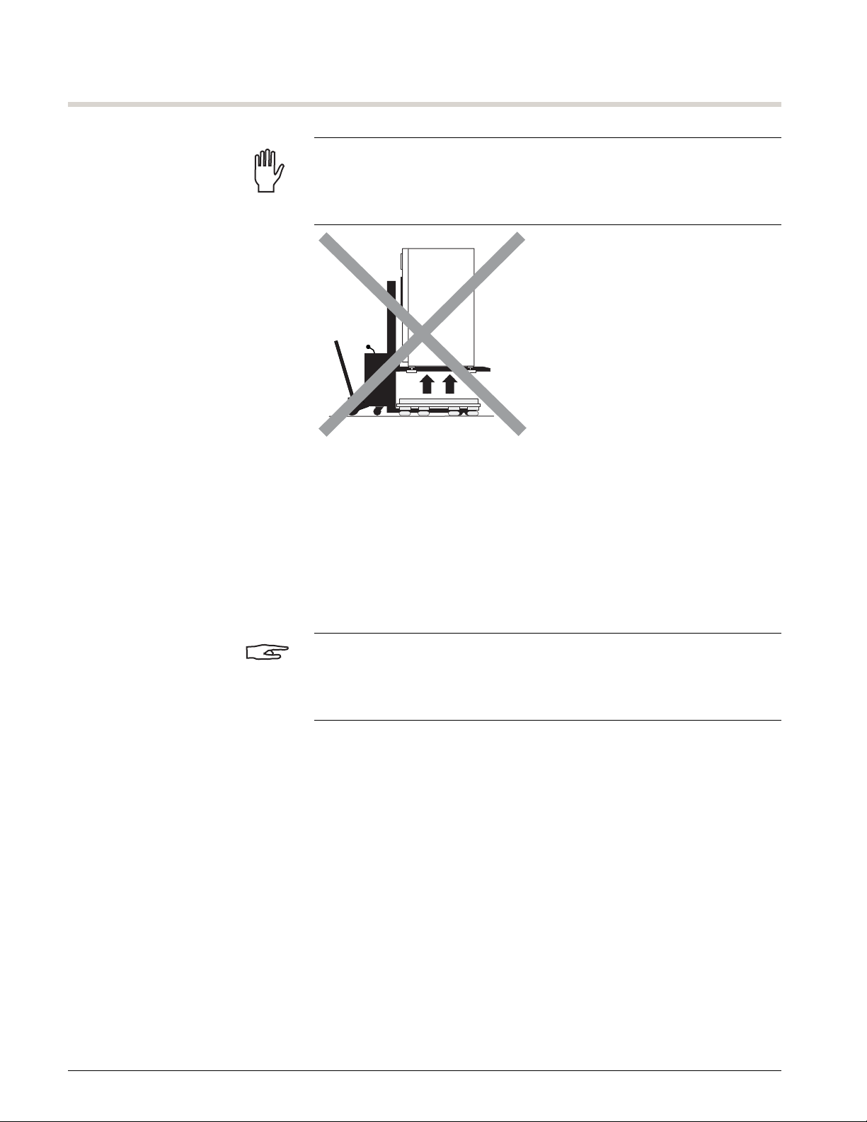
CAUTION
DAMAGE TO EQUIPMENT: Do not lift or position the sterilizer using the
cross members of the sterilizer frame. Doing so could misalign the door
assembly.
UNPACKING THE STERILIZER To unpack the sterilizer:
1. Move the sterilizer as close to the installation site as possible.
2. Refer to Figure 3–1 on page 3–3. Remove any packaging and shipping
material or tape.
3. Set aside the large carton containing the interior equipment.
NOTE
If a loading car and transfer carriage was purchased, the sterilizer carton will
contain a track for the loading car. The loading car and transfer carriage will
be shipped in a separate carton.
4. Set aside the small carton.
5. Set aside the kick panel.
3–2 INS 61301607027 Rev A US
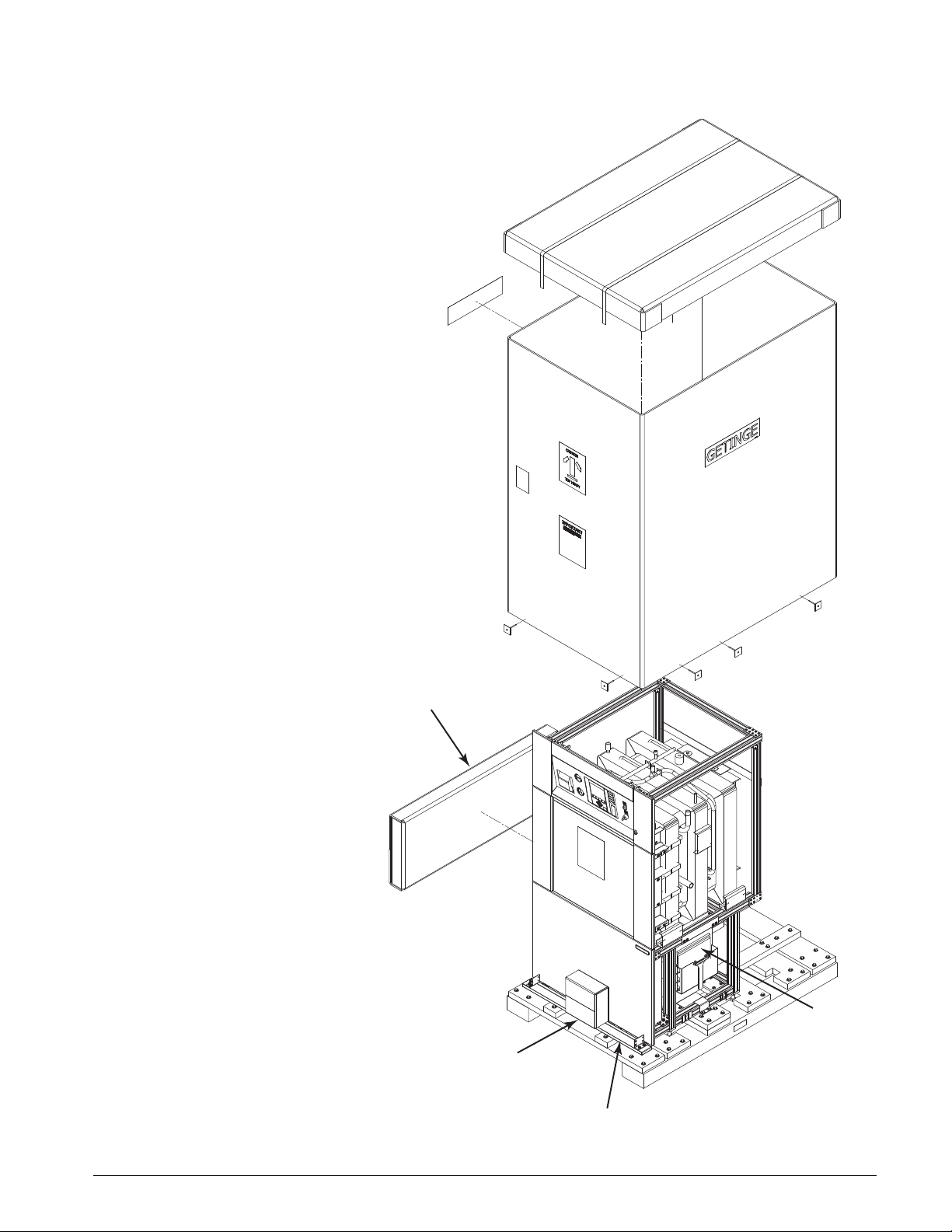
FIGURE 3–1. REMOVING THE PACKAGING
Carton containing
Interior Equipment
Kick Panel
Carton containing
Printer Paper and
Anchor Brackets
A07027-BM
Manuals
600 Series Steam Sterilizers
INS 61301607027 Rev A US 3–3
Packaging
Unlock latch
with screwdriver.
Raise and latch
front panel (see detail).
Lift side panels
off frame pins.
Lift bottom panel
off frame pins.
1
2
3
4
A07027-A2
Operator Panel
(in raised position)
Notches
Prop Rod
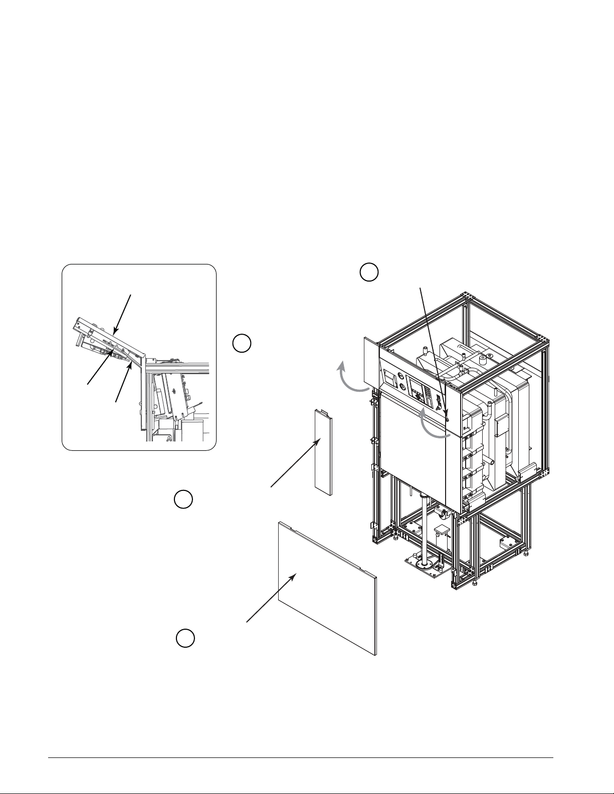
REMOVING THE STERILIZER FRONT PANELS
To remove the front panels:
1. Refer to Figure 3–2. Use a screwdriver to turn the keyhole latch and
unlock the panels.
2. Unlatch the top panel, swing it open, and prop it open with the prop
rods found on the left and right sides of the panel.
3. Lift the left and right side panels off of the frame pins. The pins slide
through the slots on either side of the panels and lift out of the slot in
the lower panel.
4. Lift the bottom panel up off of the frame pins.
FIGURE 3–2. STERILIZER FRONT PANELS
3–4 INS 61301607027 Rev A US
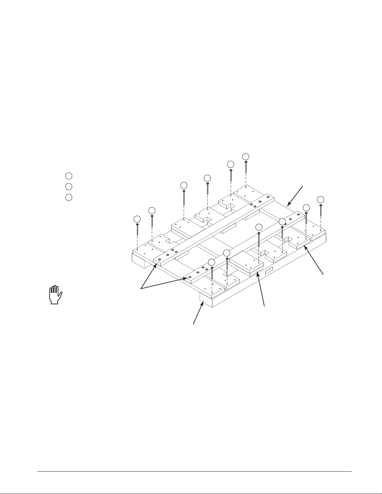
REMOVING THE SKID To remove the sterilizer from its skid:
Outer Beam
Outer
Cross Beam
Leveling Foot
Retaining Block
Center Cross Beam
and Retaining Blocks
A07027-BN
1
1
1
1
2
2
2
2
2
2
3
3
3/8 x 4 in. lag screws
1
1/2 x 4 in. lag screws
2
1/2 x 6 in. lag screws
3
Skid Hardware:
Do not remove hardware
on front to back pieces
1. Refer to Figure 3–3. Remove the hardware from the outer beams:
a. 3/8 x 4 in. lag screws (item 1) that attach the outer cross beams to
the outer beams (16 places).
b. 1/2 x 4 in. lag screws (item 2) that attach the leveling foot retaining
blocks to the outer beams. (18 places on 26 in./39 in. skid, 12
places on 51 in. skid).
c. 1/2 x 6 in. lag screws (item 3) that attach the center cross beam and
retaining blocks to the outer beams (8 places).
FIGURE 3–3. SKID HARDWARE
600 Series Steam Sterilizers
INS 61301607027 Rev A US 3–5
Packaging
A07027-BH
Outer Beam
Pallet Jack
Forks
Turn down leveling feet
(4 places) while unit is
lifted by pallet jack
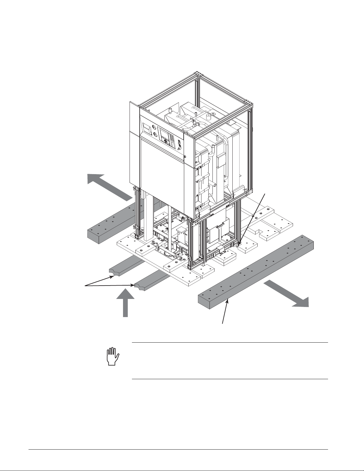
2. Using the pallet jack, raise the sterilizer skid until the outer beams can
be removed (see Figure 3–4).
FIGURE 3–4. REMOVING THE OUTER BEAMS
CAUTION
DAMAGE TO EQUIPMENT: Do not extend the leveling bolts more than 5
inches (127 mm). The bolts are 6 inches long (152 mm) and might be
damaged by the weight of the sterilizer if overextended.
3. Once the outer beams have been removed, turn down all four leveling
feet until they extend below the skid.
4. Lower the sterilizer skid until the leveling feet rest on the floor.
5. Remove the pallet jack.
3–6 INS 61301607027 Rev A US
600 Series Steam Sterilizers
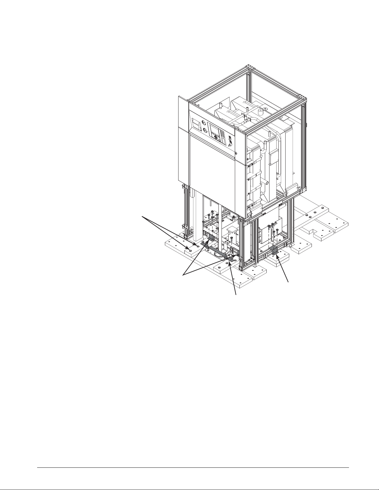
6. Remove the motor mounting plate retaining bracket(s) (see Figure 3–5).
FIGURE 3–5. REMOVING THE RETAINING BRACKETS
Remove all skid hardware
(16 places)
Front/Back
Retaining Brackets
(both ends)
7. Remove the front and back retaining brackets.
8. Remove the side retaining brackets.
9. Remove all the remaining skid hardware.
10. Disassemble and remove the rest of the shipping skid.
Side Retaining
Bracket (both sides)
Motor Plate
Retaining Bracket
A07027-BJ
INS 61301607027 Rev A US 3–7
Packaging
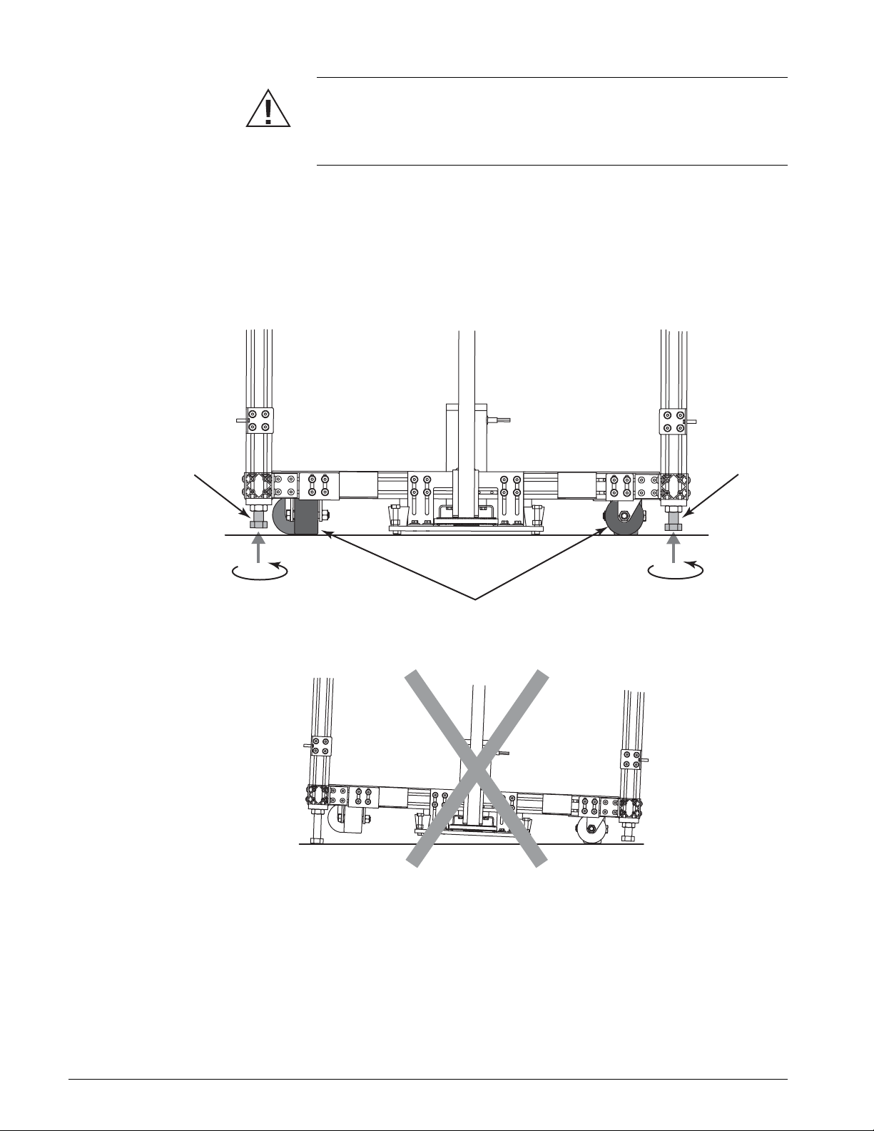
A07027-BK
Leveling
Foot
Leveling
Foot
Casters
WARNING
POSSIBILITY OF INJURY: When lowering the sterilizer onto the casters,
turn the leveling feet incrementally to keep the unit as even as possible. If
the weight of the sterilizer is not evenly distributed, it may become unstable.
11. Lower the sterilizer onto the casters:
a. Turn each leveling foot one half-turn counterclockwise.
b. Continue to turn the leveling feet incrementally until the sterilizer
rests on the casters.
FIGURE 3–6. LOWERING THE STERILIZER ONTO ITS CASTERS
12. Roll the sterilizer to its final location.
3–8 INS 61301607027 Rev A US
SECTION 4 INSTALLATION
INSTRUCTIONS
BEFORE YOU BEGIN
CAUTION
Follow the instructions in this manual to ensure safe and efficient
performance of the equipment. Failure to comply with these instructions or
to provide specific services could void the equipment warranty.
NOTE
Before installing the sterilizer, be sure the location is prepared for water,
electrical power, steam, and waste as outlined on the roughing-in drawing
(Figure 6–1, Sheet 5 on page 6–6).
Review the technical requirements for standard and optional equipment
outlined in this chapter and in Section 5, Optional Equipment.
UTILITY REQUIREMENTS The following utility connections (as specified on the roughing-in drawing)
are required for all sterilizers:
• Manual shutoff valves, pressure gauges, and steam trap (supplied by
customer) for the water and steam supplies at the sterilizer site.
NOTE
Unions must be used for the steam supply, cold water supply, and pressure
relief valve connections to the sterilizer.
• Steam Supply (S). The steam source may be either an integral steam
boiler or a facility steam supply.
• Cold Water Supply (CW). A backflow preventer (supplied by customer)
must be installed as required by local codes.
• 120 Vac Electrical Supply (E). Conveniently accessible fused
disconnect switches (supplied by customer) are required in all electrical
supply lines at the sterilizer site.
• Three-phase Electrical Supply (K). Required if an integral steam boiler
is used. Available boiler voltages are 208, 240, 480, and 600 Vac.
•Drain (D).
• Pressure Relief Valve (SV).
INS 61301607027 Rev A US 4–1
Installation Instructions
A
TOOLS AND MATERIALS REQUIRED
The following tools are required to install the sterilizer:
• 2 ft. spirit level
• torpedo level
• try square (or tape measure)
• torque driver set
• spanner wrench (supplied by Getinge—see Figure 4–1)
• 2 in. x 2 in. shims (see note below)
NOTE
Place shims under leveling feet and door motor mounting plate leveling
bolts to prevent damage to soft flooring materials such as linoleum. Single
door units require 8 shims, double door units require 16 shims.
The door alignment pins may be used as a guide when leveling the door.
See “Leveling the Sterilizer Door” on page 4–13.
FIGURE 4–1. INSTALLATION TOOLS
lignment Pins
Spanner Wrench
A07027-BL
4–2 INS 61301607027 Rev A US
POSITIONING AND LEVELING
600 Series Steam Sterilizers
CAUTION
Be careful to avoid possible surface damage to the floor when maneuvering
the sterilizer into position.
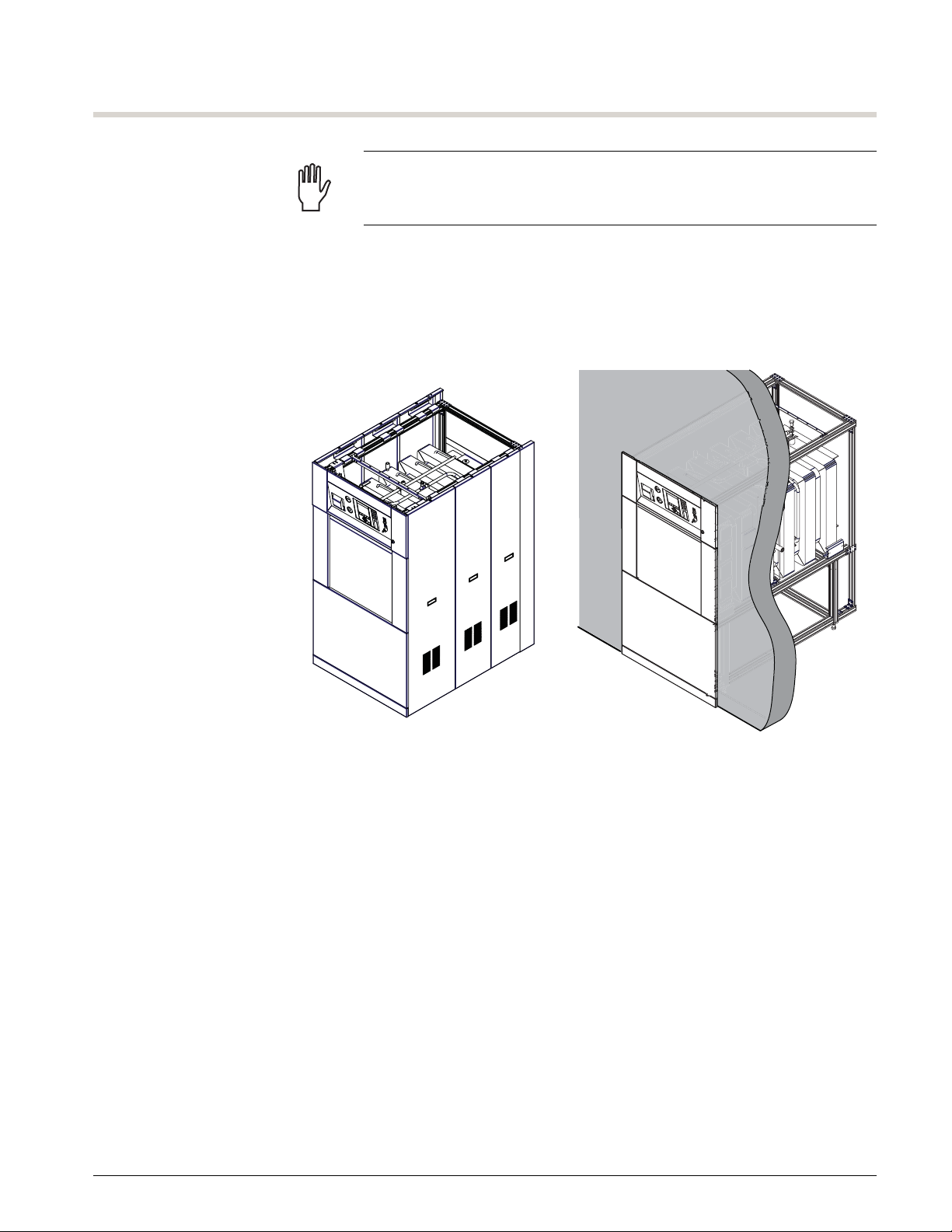
Permanent positioning is determined by the configuration of the model
being installed. Single door units may be freestanding or recessed into a
wall (see Figure 4–2).
FIGURE 4–2. SINGLE DOOR INSTALLATION
Freestanding (with Cabinet)
Recessed into Wall
SERVICE
AREA
A07028-B
INS 61301607027 Rev A US 4–3
Installation Instructions
Steam Boiler
(option)
A07027-B
Recessed at One End (with Cabinet) Recessed at Both Ends
A07028-C
CONTROL
END
CONTROL
END
REMOTE
END
REMOTE
END
SERVICE
AREA
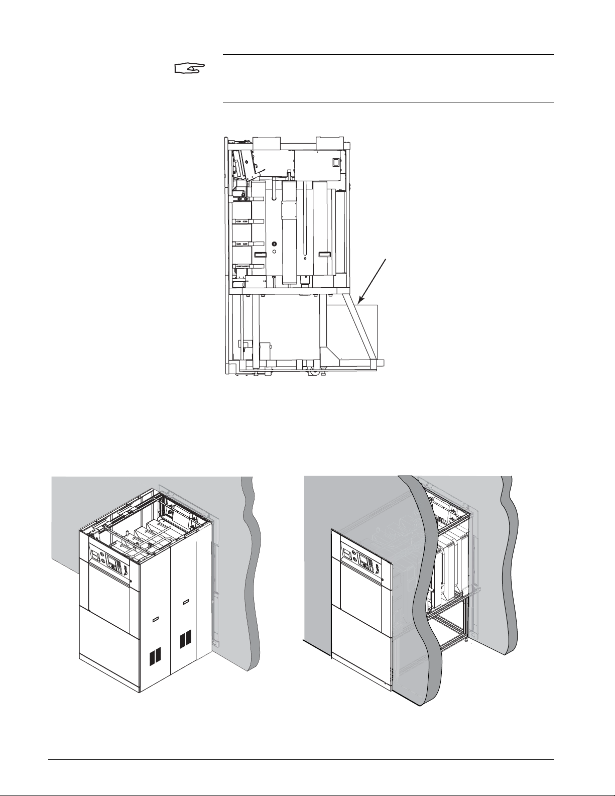
NOTE
26 IN. LENGTH WITH STEAM BOILER: The steam boiler extends beyond
the end of the sterilizer frame (see Figure 4–3).
FIGURE 4–3. 26 IN. LENGTH UNIT WITH STEAM BOILER
Double door units may be recessed into a wall at one end or both ends (see
Figure 4–4). Compliance with the roughing-in drawing specifications is
essential.
FIGURE 4–4. DOUBLE DOOR INSTALLATION
4–4 INS 61301607027 Rev A US

POSITIONING THE STERILIZER To position the sterilizer:
A07027-BY
2.25 in. (57 mm)
from nished oor
Foot Block
1. Roll the sterilizer into its final location.
FIGURE 4–5. LEVELING FEET ADJUSTMENT
600 Series Steam Sterilizers
2. Refer to Figure 4–5. From the underside of the sterilizer frame, rotate
the leveling feet in the frame until the bottom of the foot block is
approximately 2.25 inches (57 mm) above the floor (all four corners).
NOTE
This clearance is required for the installation of the kick panel(s) and
optional cabinet panels.
3. IMPORTANT: If seismic anchorage is required by local codes:
a. Position the seismic anchoring brackets on the leveling feet (see
Figure 4–25 on page 4–28).
b. Using the brackets as a template, mark the holes.
c. Raise the leveling feet and roll the sterilizer out of the way.
d. Drill the holes and install the anchoring devices into the floor. See
the seismic anchorage drawing on page 6–10.
e. Roll the sterilizer back into position.
f. Lower the leveling feet.
INS 61301607027 Rev A US 4–5

Installation Instructions
NOTE
If a loading car and transfer carriage will be used to load goods in the
sterilizer, the tracks inside the chamber must match the height of the top
plate of the transfer carriage (see Figure 4–6 on page 4–6).
The standard height of the top plate of transfer carriages is 31.50 in. (800
mm) above the floor. Because a transfer carriage may be used with several
sterilizers, adjust the sterilizer height to match the transfer carriage.
FIGURE 4–6. TRANSFER CARRIAGE HEIGHT
Loading
Car
Transfer
Carriage
31.50 in. (800 mm)
Finished Floor
A07026-BR
4–6 INS 61301607027 Rev A US

600 Series Steam Sterilizers
A07027-BP
Mounting Plate
Leveling Bolts
(4 places)
Motor Mounting Plate
Support Bracket
Shims
FIGURE 4–7. MOTOR MOUNTING PLATE LEVELING BOLTS
4. Turn down the mounting plate leveling bolts until the plate is supported
by the floor.
5. Loosen the hardware that secures the motor mounting plate support
bracket to the extrusion.
CAUTION
When tightening the mounting plate support bracket hardware, do not
exceed 15 ft-lbs maximum torque. Do not use a powered screwdriver to
tighten the screws.
6. Using a torque driver, tighten the screws on the mounting plate support
bracket to 10 ft-lbs (minimum).
WARNING
POSSIBILITY OF INJURY AND DAMAGE TO THE EQUIPMENT: Be sure the
door motor mounting plate is supported by the floor before removing the
shipping bolts.
7. Remove the shipping bolts as shown in Figure 4–8.
INS 61301607027 Rev A US 4–7

Installation Instructions
FIGURE 4–8. REMOVING THE SHIPPING BOLTS
Shipping Bolts
A07027-BT
8. Remove the two stabilizing casters from the front of the sterilizer (26 in.
length units only).
FIGURE 4–9. REMOVING THE STABILIZING CASTERS
Stabilizing
Caster
Caster Bracket
A07027-CL
4–8 INS 61301607027 Rev A US

600 Series Steam Sterilizers
LEVELING THE STERILIZER CHAMBER
Once the sterilizer is positioned, check the alignment and leveling of the
chamber. The unit must be level to run properly and align with the loading
carts.
NOTE
If power is available, connect the power to the input terminals inside the
sterilizer Power Box and use the Open Door switch to open the door.
Otherwise, the door must be opened by manually turning the lift screw. Use
a spanner wrench to turn the pulley wheel at the base of the lift screw.
To level the sterilizer chamber:
1. If power is available:
a. Connect 115 Vac to 1TB in Power Box 1A (see “Connecting the
Electrical Power” on page 4–22
).
b. Turn ON the Power Box circuit breaker.
FIGURE 4–10. STERILIZER CONTROL PANEL
CONTROLS
OFF ON
CONTROLS
ON/OFF Switch
CONTROLS
DISABLE EN ABLE
CONTROLS
ENABLE/DISABLE
Switch
Close Door
Switch
Open Door
Switch
A07027-BU
c. Press the CONTROLS ON/OFF switch on the Control Panel.
d. Turn the CONTROLS DISABLE/ENABLE switch to the ENABLE
position.
e. Press the Open Door switch.
INS 61301607027 Rev A US 4–9

Installation Instructions
A07026-D
Door Movement
Turn Pulley CCW
If power is not available:
a. Insert the spanner wrench into the holes in the pulley wheel.
NOTE
The spanner wrench is located in a holder on the right side of the sterilizer
frame.
b. Rotate the pulley wheel counterclockwise (CCW) until the door is
low enough to place a level inside the chamber.
FIGURE 4–11. MANUALLY OPENING THE STERILIZER DOOR
4–10 INS 61301607027 Rev A US

600 Series Steam Sterilizers
2. Refer to Figure 4–12 on page 4–12. Place the level vertically against the
chamber wall and adjust the feet to level the chamber from side-toside. The minimum distance from the finished floor must be a minimum
of 2.25 inches (57 mm) as shown in Figure 4–5 on page 4–5.
3. Place the level vertically against the door gasket headring and adjust
the feet to level the chamber from front-to-back. The minimum
distance from the finished floor must be a minimum of 2.25 inches (57
mm) as shown in Figure 4–5 on page 4–5.
NOTE
If a loading car and transfer carriage will be used with the sterilizer, be sure
to maintain the proper height adjustment shown in Figure 4–6 on page 4–6.
4. Once the chamber is level, tighten the locknuts on the leveling feet.
5. Raise the sterilizer door by pressing the Close Door switch or turning
the lift screw pulley clockwise.
INS 61301607027 Rev A US 4–11

Installation Instructions
FIGURE 4–12. LEVELING THE STERILIZER CHAMBER
Place level vertically
against chamber wall
Place level vertically
against gasket headring
Adjust to level chamber
front-to-back
Adjust to level chamber
side-to-side
A07027-L
4–12 INS 61301607027 Rev A US

600 Series Steam Sterilizers
LEVELING THE STERILIZER DOOR
Once the sterilizer is leveled, check the alignment of the door mechanism
to ensure that the door is level and the position of the mounting plate has
not changed.
To level the sterilizer door:
1. Remove the rubber bumpers from the door motor mounting plate. This
will allow a 9 inch torpedo level to be placed on the mounting plate.
2. Adjust the mounting plate leveling bolts until the bottom of the plate is
0.25 in. (6.3 mm) above the finished floor.
FIGURE 4–13. MOUNTING PLATE LEVELING BOLTS
Torpedo Level
0.25 in (6.3 mm)
(bottom of plate to finished floor)
Adjust to level plate
from side to side
Remove bumper to
make space for level
A07027-BE
3. Position a level as shown in Figure 4–13 and check that the mounting
plate is level from side to side.
INS 61301607027 Rev A US 4–13

Installation Instructions
A07027-AR
Mounting Plate
Adjustment Bracket
Adjust to level plate
from front to back
DO NOT adjust
mounting bolts
Torpedo Level
FIGURE 4–14. MOUNTING PLATE ADJUSTMENT BRACKETS
4. Position the level as shown in Figure 4–14 and check that the mounting
plate is level from front to back.
5. Adjust the mounting bracket as required to level the plate from front to
back.
4–14 INS 61301607027 Rev A US

600 Series Steam Sterilizers
A
A
Dimension A =
5.625 in. (143 mm)
Measure both sides
with try square
Adjust mounting bolts
only if both sides
are not equidistant
A07027-CC
FIGURE 4–15. CHECKING FOR SQUARENESS
6. Refer to Figure 4–15. Using a try square (or tape measure), measure the
distance from the front edge of the mounting plate to the bend in the
mounting bracket. Confirm that this dimension is 5.625 in. (143 mm).
Measure both the left and right sides of the mounting plate.
7. If the measurements on the left and right side of the mounting plate are
equidistant, the mounting plate is square and no adjustment is
required. If not, loosen the bolts that secure the mounting bracket to
the plate and adjust the mounting plate as required.
8. If not already installed, insert the alignment pins into the threaded holes
in the bottom of the door plate.
9. Lower the door.
INS 61301607027 Rev A US 4–15

Installation Instructions
Lift Screw
FIGURE 4–16. LIFT SCREW ALIGNMENT
Door cover removed for clarity.
Lift screw must be centered
in the openings in the door plate
Aligned Correctly
Alignment
Pins
Alignment
Holes
Not Aligned
TOP VIEW
(as viewed through opening in door cover)
Door Motor
Mounting Plate
A07027-BG
10. Refer to Figure 4–16. Check that the alignment pins are centered over
the holes in the mounting plate.
11. Remove the plug from the top of the door cover and check that the lift
screw is vertically centered in the openings in the door plate.
12. Readjust the mounting plate as required and check for levelness from
side to side and back to back.
13. Remove the alignment pins and store them on the sides of the holder
for the spanner wrench.
14. Reinstall the rubber door bumpers.
4–16 INS 61301607027 Rev A US

INSTALLING THE KICK PANEL To install the kick panel:
T-Nut
Kick Panel
Extrusion
Groove
Corner
Bracket
Back View of Kick Panel
A07027-BV
1. Loosen the screws that secure the T-nuts to the kick panel corner
bracket.
FIGURE 4–17. INSTALLING THE KICK PANEL
600 Series Steam Sterilizers
2. Align the kick panel so that the T-nuts will slide into the lower groove of
the extrusion on each slide.
3. Slide the kick panel over the extrusions until the front of the panel is
flush with the panel above.
4. Tighten the screws that secure the T-nuts to the kick panel corner
bracket.
INS 61301607027 Rev A US 4–17

Installation Instructions
RE-ATTACHING THE FRONT PANELS
To re-attach the front panels:
1. Place the bottom panel back onto the unit, aligning the holes in the
panel with the frame pins.
FIGURE 4–18. STERILIZER FRONT PANELS
Unlatch and lower front panel.
3
Lock latch with
4
screwdriver.
Install side panels
2
on frame pins.
Install bottom panel
1
on frame pins.
2. Place the pin at the bottom of one of the side panels into the slot in the
base panel and slide the side pin through the slot on the panel until the
panel is secure. Repeat the process for the other side.
3. Lower the prop rods on the top panel and close the panel.
4. Use a screwdriver to turn the latch to the locked position.
14
A07027-M
4–18 INS 61301607027 Rev A US

UTILITY REQUIREMENTS
Hot Water
Shutoff
Steam
Shutoff
Cold Water
Shutoff
Cold Water Supply
Steam Supply
(units without steam boiler)
Hot Water Supply
(units with steam boiler)
Steam Boiler
(option)
Booster Pump
(option)
115 or 230 Vac
Single-Phase
115 Vac
Integral
Transformer
(option)
UPS
(option)
UPS
(option)
Universal
Transformer
(option)
Mains
Disconnect
Circuit
Breaker
230 Vac
Voltages
> 380 Vac
Single-Phase
Power Source
Mains
Disconnect
Circuit
Breaker
Three-Phase
Power Source
Heater Voltage
A07027-BW
Power Box
600 Series Steam Sterilizers
The sterilizer requires steam, cold water and electrical supplies as specified
on the roughing-in drawing. Sterilizers with an integral boiler require a hot
water supply (instead of steam) and three-phase electrical supply as well.
FIGURE 4–19. UTILITY CONNECTIONS
INS 61301607027 Rev A US 4–19

Installation Instructions
CONNECTING THE PLUMBING
All service connections must conform with local codes. Refer to the
roughing-in drawing (see Figure 6–1, Sheet 5 on page 6–6) for supply line
pipe sizes and specification requirements for the installation site.
STERILIZER CONNECTIONS Connect the steam and cold water supplies to the sterilizer. The supply line
connections on the sterilizer are tagged for identification.
Getinge recommends installing pressure gauges in the steam and water
supply lines to monitor the incoming pressure. Since some sterilizer
malfunctions may be caused by inadequate steam or water pressure,
pressure gauges in the supply lines are useful in servicing the sterilizer.
Route the sterilizer drain line to the customer-supplied drain point. Getinge
recommends installing a flexible coupling at the drain line connection point.
Connect the outlet of the pressure relief valve to an appropriate discharge
location per local codes.
NOTE
Use unions on the steam, cold water, drain, and pressure relief valve
connections.
The steam supply to the sterilizer is to meet the steam quality specification
on the roughing-in drawing. Install a thermodynamic steam trap or MP-106
Steam Conditioning Package in order to meet the steam requirement for
the sterilizer. See “Steam Supply Quality” on page 7–3 for more information.
BOOSTER PUMP (OPTION) If the sterilizer uses a booster pump, refer to “Booster Pump Package” on
page 5–9 for installation details. The booster pump must be installed before
a cold water supply is connected to the sterilizer.
4–20 INS 61301607027 Rev A US

600 Series Steam Sterilizers
WS-0414
CAS-45A STEAM BOILER
(vertical boiler tank)
GTS-30A STEAM BOILER
(horizontal boiler tank)
STEAM BOILER (OPTION) Two models of steam boilers are used with the 600 Series sterilizer:
• GTS-30A on 26 in. length units.
• CAS-45A on 39 in. and 51 in. length units.
If the sterilizer has an integral steam boiler, refer to “Steam Boiler” on
page 5–2 for installation details.
NOTE
The hot water supply is to meet the water quality specification on the
roughing-in drawing. A water treatment system may need to be installed in
order to meet the feedwater requirement for the boiler. See “Steam Boiler
Feedwater Quality” on page 7–5 for more information.
FIGURE 4–20. STEAM BOILER MODELS
INS 61301607027 Rev A US 4–21

Installation Instructions
Disconnect switch for
Getinge USA equipment
61301608457 Rev. B
CONNECTING THE ELECTRICAL POWER
It is the customer’s responsibility to complete all electrical connections in
accordance with the National Electrical Code and all applicable local
codes.
CAUTION
Be sure the power box circuit breaker is in the OFF position to ensure that
the power supply will not energize any sterilizer components prior to
performing required adjustments and testing.
ELECTRICAL SUPPLY REQUIREMENTS
A permanently-connected, dedicated electrical supply with a conveniently
accessible disconnect switch (supplied by the customer) is required for
each sterilizer. Where both single-phase and three-phase supplies are
required, two (2) disconnect switches can be used. Disconnect switches
must be located as close to each other and to the sterilizer as possible and
within easy reach of the operator.
NOTE
Refer to roughing-in drawing (Figure 6–1, Sheet 5 on page 6–6) for
recommended breaker/fusing.
All disconnect switches need to be properly labeled as the disconnecting
devices for the specified sterilizer. Affix the Getinge USA label (part number
61301608457) supplied with the sterilizer to each disconnect switch
enclosure and indicate the sterilizer ID on the label.
FIGURE 4–21. GETINGE USA LABEL
4–22 INS 61301607027 Rev A US
NOTE
When the only electrical supply source available to operate the control
system is other than 115 Vac ±10%, 50/60Hz, single-phase, a transformer
is required to provide 115 Vac for connection to the sterilizer control circuit.
See “Connecting the Customer Supply” on page 4–23

600 Series Steam Sterilizers
CONNECTING THE CUSTOMER SUPPLY
The primary power connection procedure is dependent on the supply
voltage:
• 115 Vac—power is connected to the Power Box.
See “115 Vac Installation” below.
• 230 Vac—power is connected to the factory-installed Integral
Transformer which steps down the voltage to the 115 Vac required by
the sterilizer. See “230 Vac Installation” on page 4–24.
• 380 Vac and above—power is connected to the Universal Transformer
which steps down the voltage to 115 Vac. The Universal Transformer is
installed and wired by the customer. See “Universal Transformer” on
page 5–16.
NOTE
If the sterilizer has an uninterruptible power supply (UPS), install the UPS
before connecting power to the sterilizer. see “Uninterruptible Power
Supply (UPS)” on page 5–18 for electrical connections.
115 VAC INSTALLATION
Connect the 115 Vac 50/60 Hz single-phase supply circuit to terminals L
(hot), N (neutral), and protective ground on terminal block 1TB inside the
Power Box (see Figure 4–22).
FIGURE 4–22. CONNECTING THE POWER SOURCE (115 VAC)
J5 J4 J3 J2 J1
Power Box 1A
(with Cover Open)
Terminal Block
1TB
Customer Supply
(115 Vac ±10% Single-Phase)
A08205-K
INS 61301607027 Rev A US 4–23

Installation Instructions
230 Vac ±10%
Single-Phase Supply
A08205-H
1A
POWER BOX
9A
INTEGRAL
TRANSFORMER
BOX
(W)
(BK)
2
3
1
1TB
(G/Y)
1
2TB
2
3
(BK)
(G/Y)
(W)
(BK)
(W)
(G/Y)
NL
1TB
L1N
3
2
115 Vac
Customer Supply
(230 Vac)
Output to
Power Box 1A
(115 Vac)
LN
1TB
123
5A
2
2TB
1F
1
123
Terminal Block
1TB
Integral
Transformer
Box 9A
230 VAC INSTALLATION
Integral Transformer 9A is a factory-installed option used to step down the
230 Vac customer supply to the 115 Vac required by the sterilizer.
Connect the 230 Vac 50/60 Hz single-phase supply circuit to terminals L
(hot), N (neutral), and protective ground on terminal block 1TB inside the
Integral Transformer Box (see Figure 4–23).
FIGURE 4–23. CONNECTING THE POWER SOURCE (230 VAC)
4–24 INS 61301607027 Rev A US

600 Series Steam Sterilizers
STEAM BOILER (OPTION) The steam boiler requires two operating voltages: 115 Vac for the controls
(provided by the sterilizer) and the three-phase voltage for the heater
elements. For instructions on connecting the three-phase supply, see
“Connecting the Electrical Power” on page 5–4.
BOOSTER PUMP (OPTION) The booster pump requires a separate 115 Vac or 230 Vac single-phase
electrical supply to operate the pump motor. The control voltages for these
options are provided by the sterilizer.
For information regarding booster pump installation, see “Connecting the
Electrical Power” on page 5–14.
INS 61301607027 Rev A US 4–25

Installation Instructions
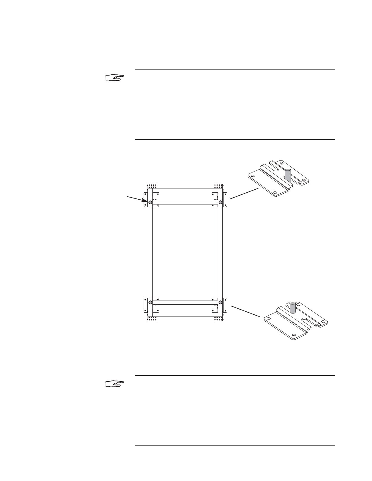
ANCHORING THE STERILIZER
The sterilizer is anchored to the floor with two hold-down brackets as
shown in Figure 4–24 on page 4–26.
NOTE
If seismic anchoring is required by local codes, the sterilizer is anchored as
described in “Installing the Seismic Anchoring Brackets” on page 4–28.
INSTALLING THE HOLD-DOWN BRACKETS
To install the hold-down brackets:
1. Remove the brackets and hardware from the small carton that was set
aside during unpacking.
2. Remove the mounting screws from the front of the left front caster.
3. Using the mounting screws provided with the bracket, install the holddown bracket.
4. Drill the mounting holes and insert the necessary anchoring devices to
accept 3/8” diameter lag bolts.
5. Repeat steps 2 thru 4 for the right rear caster. If the rear of the sterilizer
is not accessible, install the hold-down bracket in the alternate location
shown in Figure 4–24 on page 4–26.
4–26 INS 61301607027 Rev A US

FIGURE 4–24. HOLD-DOWN BRACKETS
A07027-CE
Hold-Down Bracket
(front left corner)
Hold-Down Bracket
(rear right corner)
Alternate Location
(if rear right corner
is not accessible)
Remove caster
bracket hardware
Anchoring Detail
3/8" dia. Lag Bolt
600 Series Steam Sterilizers
INS 61301607027 Rev A US 4–27
Installation Instructions
INSTALLING THE SEISMIC ANCHORING BRACKETS
Leveling Bolt
(4 places)
If seismic anchorage is required per local codes, all four leveling feet must
be anchored (see Figure 4–25). Four bolts per corner are required to meet
seismic anchoring codes.
NOTE
The anchoring specifications recommended in this manual (see seismic
anchorage drawing on page 6–10) are in compliance with seismic
anchoring codes set forth by the state of California.
It is recommended that permanent anchoring of the sterilizer to the floor be
done after the unit has been checked out by a qualified Getinge USA
service representative.
FIGURE 4–25. SEISMIC ANCHORING BRACKETS
Front Bracket
Sterilizer Frame
(Top View)
Rear Bracket
A07027-T2
NOTE
The holes cannot be drilled with the sterilizer in place because of
interference with the sterilizer frame. If the holes are not already drilled, it
will be necessary to mark the holes, move the sterilizer out of the way, drill
the holes, then move the sterilizer back to its location.
The casters must be removed to allow the seismic anchorage brackets to
anchored in four places.
4–28 INS 61301607027 Rev A US

600 Series Steam Sterilizers
K
To install the seismic anchoring brackets:
1. Remove the casters:
a. Remove the four bolts that secure the caster to the caster bracket.
b. Remove the mounting screws that secure the caster brackets to
the sterilizer frame.
FIGURE 4–26. REMOVING THE CASTERS
Caster Bracket
Hardware
Caster
Bracket
Caster
A07027-C
2. Position the seismic anchoring bracket on the leveling feet as shown in
Figure 4–27.
FIGURE 4–27. SEISMIC ANCHORING BRACKET INSTALLATION
3/8 in Lag Bolt (16 places)
(see seismic anchorage drawing)
Leveling Bolt
Lock Nut
A07027-S
INS 61301607027 Rev A US 4–29

Installation Instructions
3. Insert the lag bolts through the bracket and into the anchoring devices
in the floor.
4. Tighten the lock nut against the anchoring bracket.
4–30 INS 61301607027 Rev A US

INSTALLING THE INTERIOR EQUIPMENT
600 Series Steam Sterilizers
INSTALLING THE RACK AND SHELVES
The interior equipment package includes a left-hand shelf support, righthand shelf support, and two shelves. One or two additional shelves are
available as an option.
To install the rack and shelves:
1. Align the holes in the uprights of the shelf support with the mounting
studs on the side wall of the chamber.
2. Secure the shelf support to the mounting studs with the hardware
provided.
3. Repeat the procedure for the other shelf support.
NOTE
On 26-inch units, check that the shelf edge facing out has shelf guides.
FIGURE 4–28. INSTALLING A SHELF
Outward Facing Shelf Edge
Shelf Guide
1
3
2
WS-0218-633HC
Stop Tab Shelf GuideShelf Guide
4. Set the shelf on top of the shelf support brackets.
5. Slide the shelf back until the back edge drops down at the end of the
support bracket.
6. Pull the shelf forward until the shelf guide contacts the stop tab on the
shelf support to be sure it is properly installed. Then slide the shelf to
the back of the chamber.
INS 61301607027 Rev A US 4–31

Installation Instructions
INSTALLING THE LOADING CAR TRACK
To install the loading car track:
1. Align the holes in the bottom of the track with the mounting studs on
the floor of the chamber.
2. When the track is correctly aligned, with the mounting studs, it will drop
into place.
FIGURE 4–29. ALIGNING THE TRACK WITH THE MOUNTING STUDS
A07027-CF
4–32 INS 61301607027 Rev A US

INTRODUCTION
SECTION 5 OPTIONAL EQUIPMENT
This section includes installation instructions for the following options:
• Steam Boiler (GTS-30A or CAS-45A)—see page 5–2.
• Booster Pump Package—see page 5–9.
• Universal Transformer—see page 5–16.
• Uninterruptible Power Supply (UPS)—see page 5–18.
• Water-Saver System (MP-129F)—see page 5–22.
• Water Treatment System—see page 5–25.
• Cabinet Package—see page 5–26.
INS 61301607027 Rev A US 5–1

Optional Equipment
STEAM BOILER
SPECIFICATIONS The following utility connections are required for sterilizers with an integral
steam boiler:
• Manual shutoff valve, strainer, and pressure gauge in the hot water
supply line.
• Separate three-phase electrical service for the heating circuit.
For detailed specifications on electrical requirements, hot water (pressure,
flow, and quality), and connection sizes, refer to the roughing-in drawing
(Figure 6–1, Sheet 5 on page 6–6).
BOILER MODELS The steam boiler used varies based on the chamber length of the sterilizer.
Refer to the following table for the proper boiler unit.
TABLE 5–1. AVAILABLE STEAM BOILERS
CHAMBER LENGTH STEAM BOILER
26 in. GTS-30A
39 in. CAS-45A
51 in.
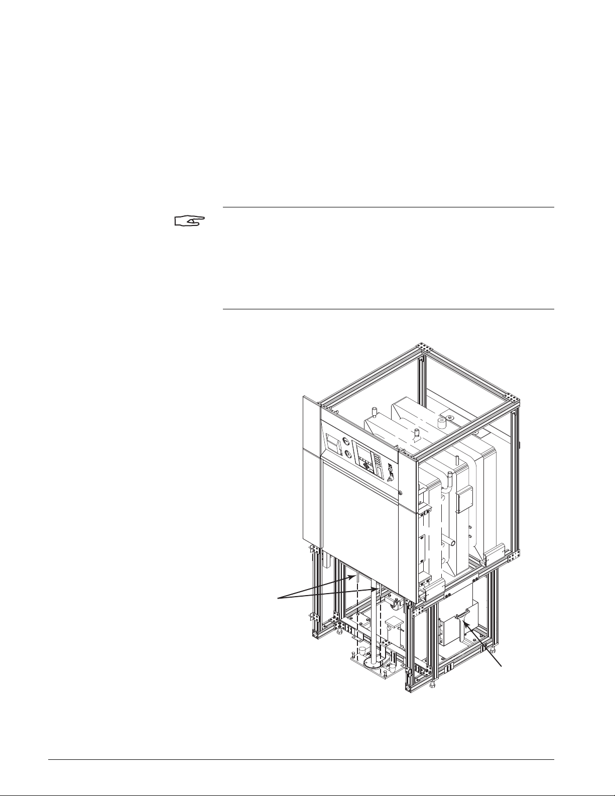
CONNECTING THE PLUMBING The steam boiler is shipped mounted to the sterilizer with the steam output
and drain line connected to the sterilizer. The hot water supply and pressure
relief valve vent are supplied by the customer.
NOTE
Use unions on the hot water supply and pressure relief valve connections.
Recommendation: Pipe the pressure relief valve to a vented manifold
outside the equipment service area per ASME code.
To connect the plumbing to the boiler (see Figure 5–1):
1. Connect the hot water (HW) supply to the water strainer on the boiler.
2. Connect the outlet of the pressure relief valve (SV3) to a vent system.
3. If the boiler is a CAS-45A, connect the blow-down discharge line to a
separator tank (provided by customer).
NOTE
The ES-18/24/30/36/48 Blow-Down Separation Tank (Getinge PN 530957)
is suitable for this application.
5–2 INS 61301607027 Rev A US

HW
SV3
Hot Water
Pressure Relief Valve Vent
A07027-P1
See Roughing-In Drawing HS4125
for Utilities Requirements
Pressure Relief
Valve
Water
Strainer
SV3
HW
HW
SV3
Pressure Relief
Valve
Water
Strainer
Blow-Down Separator
(provided by customer)
Drain
Steam
GTS-30A STEAM BOILER
(26" length units)
CAS-45A STEAM BOILER
(39" and 51" length units)
Discharge Piping
½" ID minimum
(supplied by customer)
Manual Drain
Valve
600 Series Steam Sterilizers
FIGURE 5–1. STEAM BOILER PLUMBING CONNECTIONS
INS 61301607027 Rev A US 5–3

Optional Equipment
Service Entrance for
Three-Phase Power Supply
K
Electric – 4 wire with Ground
Be sure wires are clean and bright to
ensure good electrical contact.
A07027-CJ
VOLTAGE
208V
240V
480V
600V
CURRENT
83.3 A
72.2 A
36.1 A
28.8 A
POWER
30 KW
30 KW
30 KW
30 KW
WIRE SIZE
(90°C Copper)
3 AWG
4 AWG
8 AWG
10 AWG
CONDUIT
SIZE
1¼"
1"
¾"
¾"
Three-Phase Customer
Supply Connection
(torque to 110 in-lbs)
K
Ground
Connection
ELECTRICAL CABINET
(Cover Removed)
See table below for current
ratings and wire sizes.
CONNECTING THE ELECTRICAL POWER
The steam boiler requires a separate three-phase electrical service for the
heating circuit. The sterilizer provides the 115 Vac required for the boiler
control circuits. Refer to the roughing-in drawing (Figure 6–1 on page 6–2)
for electrical specifications.
To connect the three-phase electrical supply to the steam boiler:
1. Remove the access cover from the steam boiler cabinet.
2. Refer to Figure 5–2 (GTS-30A) or Figure 5–3 on page 5–5 (CAS-45A).
Connect L1, L2, and L3 to the three-phase terminal. Torque the
terminals to 110 in-lbs.
3. Connect the ground wire to the ground terminal. The ground terminal is
located adjacent to the three-phase terminal.
FIGURE 5–2. GTS-30A STEAM BOILER ELECTRICAL CONNECTIONS
5–4 INS 61301607027 Rev A US

600 Series Steam Sterilizers
A07027-R
VOLTAGE
208V
240V
480V
600V
125.1 A
108.4 A
54.2 A
43.4 A
POWER
45 KW
45 KW
45 KW
45 KW
WIRE SIZE
(90°C Copper)
2 AWG
3 AWG
8 AWG
8 AWG
CONDUIT
SIZE
1¼"
1¼"
¾"
¾"
CURRENT
K
K
Electric – 4-wire with ground
See table below for current ratings
and wire sizes.
Three-Phase Customer
Supply Connection
(torque to 110 in-lbs.)
Ground
Connection
Wiring to Fuse Box
(208 Vac model only)
Service Entrance for
Three-Phase Power Supply
Be sure wires are clean and bright to
ensure good electrical contact.
NOTE
The 208 Vac version of the CAS-45A has a fuse box mounted on the right
side of the electrical cabinet.The customer three-phase connection is
routed through six 100A fuses before it is connected to the heating element
contactors. For all other voltages, the customer three-phase connection is
routed to the heating element contactors.
FIGURE 5–3. CAS-45A STEAM BOILER ELECTRICAL CONNECTIONS
INS 61301607027 Rev A US 5–5

Optional Equipment
CHECKING THE HEATER CIRCUIT CONNECTIONS
CAUTION
IMPORTANT: The element flange bolts, element terminals, contactor
terminals and customer three-phase supply terminals must be tightened to
the specifications shown in Figure 5–4 on page 5–7 (GTS-30A) or
Figure 5–5 on page 5–8 (CAS-45A).
To check the heater circuit connections for tightness:
1. Check the torque of the three-phase supply terminals. Tighten
connections to 110 in-lbs.
2. Check the torque of the contactor terminals. Tighten connections to 45
in-lbs.
3. Check the torque of the heating element terminals. Tighten terminals to
20 in-lbs.
4. Check the torque of the heating element flange bolts. Tighten the bolts
to 22 ft-lbs in the sequence shown in Figure 5–4 and Figure 5–5.
5–6 INS 61301607027 Rev A US

600 Series Steam Sterilizers
CB-19
Three-Phase Supply Terminals
To rque to 110 in-lbs
Contactor Terminals
To rque to 45 in-lbs
Element Terminals
To rque to 20 in-lbs
Element Flange Bolts
To rque to 22 ft-lbs
1
2
3
4
5
6
FLANGE BOLT TIGHTENING SEQUENCE
(Heating elements not shown for clarity)
ELECTRICAL CABINET
FIGURE 5–4. GTS-30A BOILER TORQUE SPECIFICATIONS
INS 61301607027 Rev A US 5–7

Optional Equipment
Three-Phase Supply Terminals
To rque to 110 in-lbs
Contactor Terminals
To rque to 45 in-lbs
Element Terminals
To rque to 20 in-lbs
Element Flange Bolts
To rque to 22 ft-lbs
A07027-BX
1
2
3
4
5
6
FLANGE BOLT TIGHTENING SEQUENCE
(Heating elements not shown for clarity)
FIGURE 5–5. CAS-45A BOILER TORQUE SPECIFICATIONS
5–8 INS 61301607027 Rev A US

600 Series Steam Sterilizers
BOOSTER PUMP PACKAGE
A booster pump package is available for sterilizer installations where the
cold water supply pressure is at least 30 psig dynamic but less than 45 psig
dynamic. When energized, the pump increases the cold water supply
pressure to the sterilizer, providing the necessary pressure required for
normal sterilizer operation (see Figure 6–1, Sheet 5 on page 6–6).
NOTE
The booster pump must be installed before connecting the cold water
supply to the sterilizer.
TYPICAL INSTALLATION The customer must provide a location for installing the pump and junction
box as well as fastening hardware for mounting the pump and junction box.
The following plumbing connections (provided by the customer) are
required:
• a plumbing connection between the discharge orifice of the booster
pump and the water supply inlet orifice (i.e., strainer) of the sterilizer.
This connection must include a pressure gauge.
• a plumbing connection between the suction orifice of the booster
pump and the customer’s water supply (a union is recommended for
this connection).
• a shutoff valve in the water supply line at the sterilizer site.
The following electrical connections (provided by the customer) are
required:
• Electrical supply as indicated on the roughing-in drawing.
• Electrical connection to the booster pump junction box per code
requirements.
Figures 5–6 through 5–12 show a typical installation of the booster pump
package. The actual configuration will depend on the desired location of
the pump and its I/F (interface) box (by customer), as well as the particular
structure of the sterilizer and the sterilizer site.
INS 61301607027 Rev A US 5–9

Optional Equipment
Water to Ejector
Solenoid Valve 6SV
(26 in. Length)
Water Supply
Strainer
24 Vac
Cold Water
Cold Water Supply
with Shutoff Valve
(by customer)
Discharge
Suction
115 Vac or 230 Vac
Single-Phase Supply
(by customer)
Pump Motor
Voltage
24 Vac from
Control Box
24 Vac to 6SV
Booster Pump
Junction Box
Booster
Pump
Control Box
A07027-N
This illustration shows a unit with a 26 in. length chamber.
On units with a 39 in. or 51 in. length chamber, the water supply
strainer is located in the upper piping.
Union
(recommended
by Getinge)
FIGURE 5–6. TYPICAL BOOSTER PUMP INSTALLATION
5–10 INS 61301607027 Rev A US

600 Series Steam Sterilizers
11A
Booster Pump
Interface Box
Interconnect Cable
(by customer)
115 or 230 Vac
Single-Phase
Electrical
Supply
350069-B
Fused
Disconnect
11A
Booster Pump
Interface Box
8A
Universal
Tran sformer
Interconnect Cable
(by customer)
115 or 230 Vac
Single-Phase
Electrical
Supply
350069-C
FIGURE 5–7. TYPICAL INTERFACE BOX INSTALLATION
NOTE
If the mains voltage is 380/400/415 Vac or 440/460/480 Vac, a universal
transformer will be required to provide 115 Vac or 230Vac for the booster
pump junction box. (See page 5–16.)
FIGURE 5–8. TYPICAL INTERFACE BOX INSTALLATION
(WITH UNIVERSAL TRANSFORMER)
INS 61301607027 Rev A US 5–11

Optional Equipment
3.00 in
(76 mm)
4.88 in
(124 mm)
Lag Screws
or Alternate
(by customer)
Booster Pump
Mounting Plate
with 13/32” (10.3 mm)
diameter holes
Mounting Surface
(by customer)
350069-D
MOUNTING THE BOOSTER PUMP AND INTERFACE BOX
To mount the booster pump:
1. Fasten the booster pump to its mounting surface as shown in
Figure 5–9.
FIGURE 5–9. MOUNTING THE BOOSTER PUMP
2. Fasten the interface box to its mounting surface as shown in
Figure 5–10.
FIGURE 5–10. MOUNTING THE INTERFACE BOX
Booster Pump
I/F Box
7/32” (5.56 mm)
diameter holes
Fastener
(by customer)
7.00
(178 mm)
7.00
(178 mm)
Mounting Surface
(by customer)
WS-0333
5–12 INS 61301607027 Rev A US

CONNECTING THE PLUMBING Make the following plumbing connections:
WS-0242
Suction Orice
(1¼ NPT)
Discharge Orice
(¾ NPT)
to Cold Water
Inlet on Sterilizer
(¾ NPT)
Pressure Gauge
and Shutoff Valve
(by customer)
CW
CW
Cold Water
See Roughing-In Drawing for
Utilities Requirements
Union
(recommended)
1. Connect the plumbing between the ¾ NPT pump discharge orifice and
the ¾ NPT inlet orifice at the sterilizer water supply strainer.
NOTE
The customer must provide a pressure gauge in the plumbing connection
between the pump discharge orifice and the sterilizer water strainer.
The customer must provide a shutoff valve in the water supply line to the
sterilizer.
2. Connect the plumbing between the 1¼ NPT pump suction orifice and
the water supply line.
NOTE
The pipe size must be 1½ in. OD minimum (the minimum flow rate must be
at least 5.1 gallons/minute).
600 Series Steam Sterilizers
FIGURE 5–11. BOOSTER PUMP PLUMBING CONNECTIONS
INS 61301607027 Rev A US 5–13

Optional Equipment
CONNECTING THE ELECTRICAL POWER
To connect the single-phase supply to the booster pump junction box:
1. Connect the booster pump junction box to the booster pump as shown
in Figure 5–12 on page 5–15.
CAUTION
Route the cord so that it does not touch any hot steam lines or sterilizer
surfaces.
2. Connect the cords from the booster pump interface box to the sterilizer
control box.
a. Disconnect the cord from 6JO on the back of the control box (that
goes to solenoid valve 6SV) and connect it to 11A2J on the booster
pump interface box.
b. Using the cord provided (P/N 61311601245), connect 11A1J on the
junction box to 2A6JO on the control box.
3. Connect the electrical supply (provided by the customer) to the booster
pump interface box as follows:
a. Connect Line (L) to 1K relay terminal 1 (L1).
b. Connect Neutral (N) to 1k relay terminal 3 (L2).
c. Connect Protective Earth Ground (G) to the PE Ground screw
inside the box.
4. Install the overload relay inside the interface box and connect the wires
as shown in Figure 5–12 on page 5–15.
5. Set the overload relay current adjustment to match the current
stamped on the rating plate.
5–14 INS 61301607027 Rev A US

1B
8A
Universal
Transformer
Water Booster
Pump
To
Water to Ejector
Solenoid Valve
6SV
11A1P4(BK)
11A1P1 (R)
2A6PO
132
4
6JO
11A1K6(W)
11A1K2(BK)
11AGND(G)
6SV(W)
6SV(BK)
2A6PO4 (BK)
2A6PO1 (R)
1P
1KA1
1J
1
4
1K96
2
3
1K96
1KA1
2J
95
1P1
1K4
A2
A1
2P1
1KA2
1K95
5
3
1
1K
1B(BK)
2P4
96
1P4
1B(W)
1K5
1B(G)
4
(W)
(BK)
L2
L1
2
3
1
1TB
(G)
Customer Supply
115 or 230
Vac
Single-Phase
380/400/415 Vac
440/460/480 Vac
Single-Phase
or
Customer
Supply Wires
11A
Pump I/F Box
2A
Control Box
5
3
1
6
4
2
6
4
2
4
3
2
1
2P
Overload
Relay
Customer Supply
(115 or 230 Vac Single-Phase)
Pump Motor
Contactor 1K
to
Booster Pump
1B
From 2A6PO
(Water to Ejector)
Front View of Box
w/o Cover
to
Water to Ejector
Solenoid Valve
6SV
Customer Supply
Current
Adjustment
1J
2J
A08205-G
600 Series Steam Sterilizers
FIGURE 5–12. BOOSTER PUMP ELECTRICAL CONNECTIONS
INS 61301607027 Rev A US 5–15

Optional Equipment
UNIVERSAL TRANSFORMER
When the customer power supply is 380 Vac or above, a transformer is
required to step down the voltage to the 115 Vac required by the sterilizer
controls. The customer is to provide:
• mounting of the transformer box.
• a connection from the transformer to the sterilizer power box.
• a connection from the customer supply (mains) to the transformer that
meets local code requirements.
• the required fused disconnects.
CAUTION
If a UPS will be installed, see UPS Installation Instructions (Pub. No.
61301605360) for electrical connections.
FIGURE 5–13. POWER SUPPLY CONNECTIONS
Customer Supply
Universal
Transformer
8A
Output to Power Box
(115 Vac)
380/400/415/440/460/480 Vac
Single Phase Supply
8A
UNIVERSAL
TRANSFORMER
1TB
(G)
L1 L2
312
4
(BK)
(W)
1A
POWER BOX
Wire Transformer Taps
for Customer Supply Voltage
(see Diagram Inside Box)
1TB
2
3
L1N
(W)
(BK)
(G/Y)
115 Vac
A08205-B
5–16 INS 61301607027 Rev A US

600 Series Steam Sterilizers
CONNECTING THE TRANSFORMER
To connect the transformer:
1. After the transformer is installed, make the mains power supply
connections (L1 & L2) at the transformer terminal block as shown in
Figure 5–13 on page 5–16.
2. Wire the primary taps of the transformer for the correct voltage (See
chart located on the inside cover of the transformer).
3. Make the electrical connections from the sterilizer power box (1A) to
the transformer (8A) as shown in Figure 5–13 on page 5–16.
INS 61301607027 Rev A US 5–17

Optional Equipment
A08214-A
UNINTERRUPTIBLE POWER SUPPLY (UPS)
NOTE
Read the manufacturer’s instruction manual before installing the UPS. After
the UPS has been installed, leave the UPS manual with the equipment to
ensure that it will be available for future reference.
Two types of uninterruptible power supplies (UPS) are available:
• UPS Package, 115 Vac (Part No. 61301602038)
• UPS Package, 230 Vac (Part No. 61301609065)
FIGURE 5–14. UNINTERRUPTIBLE POWER SUPPLY (UPS)
5–18 INS 61301607027 Rev A US

FIGURE 5–15. UPS BACK PANEL
115 Vac Model
230 Vac Model
Connect to
Power Box 1A
Connect to
Mains Disconnect
Connect to
Mains Disconnect
Connect to
Transformer Box 9A
Input
Receptacle
Output
Receptacle
A07027-AS
600 Series Steam Sterilizers
UNPACKING Check the contents against the bill of material provided in the UPS
package.
MOUNTING When selecting a location for the UPS, observe the manufacturer’s
recommendations for operating temperature and relative humidity.
Observe the following restrictions:
• Locate the UPS within 10 feet (3 meters) of Power Box Assembly 1A.
• Do not mount the UPS on the sterilizer frame.
INS 61301607027 Rev A US 5–19

Optional Equipment
1A
POWER BOX
10A
UNINTERRUPTIBLE
POWER SUPPLY
(W)
(BK)
2
3
1
1TB
(G/Y)
1
2TB
2
3
(BK)
(G/Y)
(W)
(BK) or (BR)
(W) or (BL)
(G/Y)
NL
1TB
L1N
3
2
(230 Vac Model)
230 Vac ±10%
Single-Phase Supply
A08205-A2
230 Vac
115 Vac
9A
INTEGRAL
TRANSFORMER
BOX
CONNECTING THE ELECTRICAL POWER
115 Vac ±10%
Single-Phase Supply
To connect the UPS:
1. Prepare the UPS cables as described in the UPS Installation
Instructions (Pub. No. 61301605360).
NOTE
The UPS cables are marked with their destination (e.g., 120V Supply, 1A
Power Box). The cable that connects to the sterilizer is fitted with a liquidtight connector.
2. Connect the UPS to the sterilizer:
a. If the mains voltage is 115 Vac, connect the UPS directly to Power
Box 1A (see Figure 5–16).
FIGURE 5–16. UPS CONNECTION (115 VAC)
1TB
2
3
L1N
1A
POWER BOX
(BK)
(W)
(G/Y)
10A
UNINTERRUPTIBLE
POWER SUPPLY
(115 Vac Model)
b. If the mains voltage is 230 Vac, connect the UPS to Integral
Transformer Box 9A (see Figure 5–17).
FIGURE 5–17. UPS CONNECTION (230 VAC)
A08205-A1
5–20 INS 61301607027 Rev A US

600 Series Steam Sterilizers
(W)
(G)
(BK)
1TB
L1 L2
312
4
380/400/415/440/460/480 Vac
Single-Phase Supply
A08205-D
8A
UNIVERSAL
TRANSFORMER
1A
POWER BOX
10A
UNINTERRUPTIBLE
POWER SUPPLY
(W)
(BK)
(G/Y)
1TB
L1N
3
2
(115 Vac Model)
115 Vac
c. If the mains voltage is 380 Vac or above, connect the UPS between
Universal Transformer 8A and Power Box 1A (see Figure 5–18).
FIGURE 5–18. UPS CONNECTION (OTHER VOLTAGES)
INS 61301607027 Rev A US 5–21
3. Connect the UPS to the mains disconnect.

Optional Equipment
WATER-SAVER SYSTEM
The MP-129F Water-Saver is an add-on system that incorporates a water
ejector with a pump and a water reservoir to recirculate the water that
creates the vacuum necessary for part of the sterilization cycle.
Installation of the water-saver consists of:
• Locating, mounting, and anchoring the unit.
• Connecting the cold water supply tubing.
• Connecting the overflow drain line
• Connecting the water-saver to the sterilizer piping (see Figure 5–19 on
page 5–23).
• Connecting the electrical power to the water-saver I/F Box (see
Figure 5–20 on page 5–24).
• Connecting the water-saver to the sterilizer controls (see Figure 5–20
on page 5–24).
The customer must provide a proper drainage system, cold water supply,
and electrical service. Refer to MP–129 (E & F) WATER-SAVER Installation
Instructions (Pub. No. 61301605429).
WARNING
Turn off all electricity, water, and steam to the sterilizer before starting the
installation of the water-saver. Touching live electrical connections and/or
exposure to live steam could cause serious injury.
5–22 INS 61301607027 Rev A US

600 Series Steam Sterilizers
A08205-F
(30–60 PSIG)
WATER
SUPPLY
2ST
6SV
5SV
2SV
15SV
AI-04
5RT
DRAIN
5CV
9CV
DO-06
CE RE
INSTRUMENTATION DIAGRAM
W/EJECTOR VACUUM & WATER SAVER
JKT JKT JKT
JKT JKT JKT
CHAM
VALIDATION PORT
DOOR SEAL A
DOOR SIDE A
DOOR SEAL B
DOOR SIDE B
CHAMBER
NOTES:
REFER TO CORRESPONDING PROCESS
DIAGRAM (REFERENCED IN THE UNIT’S
SOFTWARE PACKAGE) FOR CYCLE PHASE
DIAGRAMS AND PROCESS DESCRIPTION.
CE = CONTROL END (SIDE A)
RE = REMOTE END (SIDE B)
1)
2)
WATER SAVER
EXISTING COMPONENTS
ON STANDARD P&ID’s
EXISTING CONNECTIONS
ON STANDARD P&ID’s
SIGNAL TO DEVICE
SOLENOID VALVE
(NORMALLY CLOSED
TWO-WAY VALVE)
CHECK VALVE
STRAINER
EJECTOR
LEGEND
FIGURE 5–19. STERILIZER PIPING WITH WATER-SAVER INSTALLED
NOTE
The Water-Saver requires a separate 115 Vac, 60 Hz (26A rating) or 230 Vac,
60 Hz (13A rating) mains supply.
INS 61301607027 Rev A US 5–23

Optional Equipment
Overload
Relay
Customer Supply
115 or 230 Vac
Single-Phase
Pump Motor
Contactor 1K
(Single-Phase Voltage
to Pump Motor)
Front View of Box
w/o Cover
Customer Supply
Current
Adjustment
1J
2J
to Control Box
2A15JO
to Water Saver On
Solenoid Valve 15SV
Y Adapter
Sterilizer Components
(to Water to Tank
Solenoid Valve 1SV
via Temp. Switch 1S)
A08205-E
FIGURE 5–20. WATER-SAVER ELECTRICAL CONNECTIONS
5–24 INS 61301607027 Rev A US

WATER TREATMENT SYSTEM
Concentrate Out
(Brine)
Permeate Out
(Boiler Feed)
Hot Water In
Cold Water In
Hot Water
Inlet
Steam
Outlet
Steam
Boiler
Drain
Sterilizer
Drain
633HC
Steam Sterilizer
Drain System
Water
Treatment
System
A07027-U
600 Series Steam Sterilizers
At some installations, the feedwater supply to the steam boiler may require
treatment in order to meet the Steam Boiler Feedwater Quality specification
on the installation drawing.
NOTE
Reverse osmosis (RO) water treatment systems of various capacities may
be purchased from Getinge. The Model HS-300 Water Treatment System
meets the requirements of one 633HC Steam Sterilizer. For installations
where one water treatment system will supply multiple sterilizers, consult
your Getinge representative.
The manufacturer’s instruction manual includes important maintenance
information. After the water treatment system is installed, leave the manual
with the equipment to ensure that it will be available for future reference.
Connect the permeate water out (RO) supply from the water treatment
system to the hot water inlet on the steam boiler.
FIGURE 5–21. TYPICAL WATER TREATMENT PIPING
INS 61301607027 Rev A US 5–25

Optional Equipment
CABINET PACKAGE
Cabinet packages are available for single door units and double door units
that are recessed in a wall at one end (see Figure 5–22).
FIGURE 5–22. CABINET PACKAGE
Single Door Unit
Double Door Unit
(recessed in wall at one end)
A07027-G
5–26 INS 61301607027 Rev A US

600 Series Steam Sterilizers
UNPACKING The number and the width of the side panels varies with the length and door
configuration. When unpacking the cabinet package, check the contents
against the bills of material below:
TABLE 5–2. CAB PKG,SD,26”,600 (P/N 61301607311)
Item Description Part Number Qty
1 PANEL,SIDE,CAB,20"",100/200 61301601413 2
2 HANDLE,POCKET,PULL 61301600946 4
3 BRKT,LWR,CABINET,26"",600 61301607316 2
4 LATCH,ADJUST,COMPRESS,SOUTHCO 61301608549 4
5 BRKT,MTG,TOP,CABINET PKG,600 61301607317 4
6 PANEL,SIDE,CAB,15"",100/200 61301601414 2
7 PANEL,SIDE,CAB,TRIM,10""100/200 61301601415 2
8 SCR,S/TP,PAN HD,.16-32X .38,41 E7264 4
TABLE 5–3. CAB PKG,SD,26”,W/BOILER,600 (P/N 61301607318)
Item Description Part Number Qty
1 PANEL,SIDE,CAB,20"",100/200 61301601413 4
2 HANDLE,POCKET,PULL 61301600946 4
3 BRKT,MTG,TOP,CABINET PKG,600 61301607317 4
4 LATCH,ADJUST,COMPRESS,SOUTHCO 61301608549 4
5 BRKT,BOILER,CAB PKG,26"",600 61301607319 2
6 SCR,S/TP,PAN HD,.16-32X .38,41 E7264 4
7 PANEL,SIDE,TRIM,CAB,400/500 61301608474 2
TABLE 5–4. CAB PKG,SD,39”,600 (P/N 61301607312)
Item Description Part Number Qty
1 BRKT,RT,CABINET PKG,39"",600 61301607323 2
2 BRKT,MTG,TOP,CABINET PKG,600 61301607317 6
3 PANEL,SIDE,CAB,20"",100/200 61301601413 2
4 PANEL,SIDE,CAB,15"",100/200 61301601414 4
5 LATCH,ADJUST,COMPRESS,SOUTHCO 61301608549 6
6 PNL,SIDE,CAB,TRIM,6"",600 61301607324 2
7 HANDLE,POCKET,PULL 61301600946 6
8 SCR,S/TP,PAN HD,.16-32X .38,41 E7264 4
INS 61301607027 Rev A US 5–27

Optional Equipment
TABLE 5–5. CAB PKG,SD,51”,600 (P/N 61301607313)
Item Description Part Number Qty
1 BRKT,CABINET PKG,51"",600 61301607326 2
2 BRKT,MTG,TOP,CABINET PKG,600 61301607317 6
3 PANEL,SIDE,CAB,20"",100/200 61301601413 6
4 LATCH,ADJUST,COMPRESS,SOUTHCO 61301608549 6
5 SCR,S/TP,PAN HD,.16-32X .38,41 E7264 4
6 HANDLE,POCKET,PULL 61301600946 6
7 PANEL,SIDE,CAB,TRIM,10""100/200 61301601415 2
TABLE 5–6. CAB PKG,DD,39”,600 (P/N 61301607314)
Item Description Part Number Qty
1 BRKT,RT,CABINET PKG,39"",600 61301607323 2
2 BRKT,MTG,TOP,CABINET PKG,600 61301607317 4
3 PANEL,SIDE,CAB,20"",100/200 61301601413 4
4 LATCH,ADJUST,COMPRESS,SOUTHCO 61301608549 4
5 HANDLE,POCKET,PULL 61301600946 4
6 SCR,S/TP,PAN HD,.16-32X .38,41 E7264 4
7 PANEL,SIDE,CAB,TRIM,10""100/200 61301601415 2
TABLE 5–7. CAB PKG,DD,51”,600 (P/N 61301607315)
Item Description Part Number Qty
1 BRKT,CABINET PKG,51"",600 61301607326 2
2 BRKT,MTG,TOP,CABINET PKG,600 61301607317 6
3 PANEL,SIDE,CAB,20"",100/200 61301601413 2
4 PANEL,SIDE,CAB,15"",100/200 61301601414 4
5 PANEL,SIDE,TRIM,CAB,400/500 61301608474 2
6 LATCH,ADJUST,COMPRESS,SOUTHCO 61301608549 6
7 SCR,S/TP,PAN HD,.16-32X .38,41 E7264 4
8 HANDLE,POCKET,PULL 61301600946 6
5–28 INS 61301607027 Rev A US

PREPARING THE SIDE PANELS To prepare the side panels:
1. Insert the handle into the side panel.
2. Install the latch in the hole on the top of the panel as shown in
Figure 5–23.
FIGURE 5–23. PREPARING THE PANELS
600 Series Steam Sterilizers
Panel
Lockwasher
Latch
Trim Washer
Mounting Nut
Handle
A07027-AJ
INS 61301607027 Rev A US 5–29

Optional Equipment
INSTALLING THE SUPPORT BRACKETS
Refer to Figure 5–24. Each cabinet package has two bottom support
brackets and either four or six top support brackets depending on the
number of side panels in the package.
FIGURE 5–24. SUPPORT BRACKETS
Bottom Support
Bracket
Top Support
Bracket
A07027-F
To install the support brackets:
1. Place the bottom support bracket on the lower frame as shown in
Figure 5–25.
FIGURE 5–25. INSTALLING THE BOTTOM SUPPORT BRACKET
3.5"
(89 mm)
Bottom Support
A07027-H
Bracket
2. Place the top support brackets at the locations shown in Figure 5–26.
NOTE
The sterilizer frame has a channel on all sides. The top support brackets
have tabs that fit in the channel to secure the brackets to the frame.
5–30 INS 61301607027 Rev A US

Four Upper Support Brackets
A
B
C
39" Single Door 7.00 in. (178 mm) 23.50 in. (597 mm) 28.75 in. (730 mm)
51" Single Door 7.00 in. (178 mm) 23.50 in. (597 mm) 45.00 in. (1143 mm)
51" Double Door 7.00 in. (178 mm) 23.50 in. (597 mm) 40.00 in. (1016 mm)
26" 7.00 in. (178 mm) 24.50 in. (622 mm) N/A
26" with Boiler 7.00 in. (178 mm) 23.50 in. (597 mm) N/A
39" Double Door 7.00 in. (178 mm) 25.50 in. (648 mm) N/A
A
B
A
B
C
STERILIZER LENGTH
DIMENSIONS
Six Upper Support Brackets
A07027-C
Grooves in
Extrusion
Ta b
Top Support Bracket
600 Series Steam Sterilizers
FIGURE 5–26. TOP SUPPORT BRACKET LOCATIONS
INS 61301607027 Rev A US 5–31

Optional Equipment
A07027-AK
Trim Panel
Self-Tapping
Screws
20 in. Wide Panel
15 in. Wide Panel
HANGING THE PANELS To hang the panels:
1. Refer to Figures 5–27 thru 5–32. Hang the panels on the support
brackets and latch them in place.
2. Attach the trim panels to the side panels using the self-tapping screws
provided.
FIGURE 5–27. HANGING THE PANELS (26 IN. WITHOUT BOILER)
5–32 INS 61301607027 Rev A US

600 Series Steam Sterilizers
FIGURE 5–28. HANGING THE PANELS (26 IN. WITH BOILER)
Self-Tapping
Screws
10 in.
Trim Panel
20 in. Wide Panels
A07027-BF
INS 61301607027 Rev A US 5–33

Optional Equipment
A07027-AL
6 in. Trim Panel
Self-Tapping
Screws
20 in. Wide Panel
15 in. Wide Panels
FIGURE 5–29. HANGING THE PANELS (39 IN. SINGLE DOOR)
5–34 INS 61301607027 Rev A US

600 Series Steam Sterilizers
FIGURE 5–30. HANGING THE PANELS (39 IN. DOUBLE DOOR)
Self-Tapping
Screws
10 in. Trim Panel
20 in. Wide Panels
A07027-AM
INS 61301607027 Rev A US 5–35

Optional Equipment
FIGURE 5–31. HANGING THE PANELS (51 IN. SINGLE DOOR)
Screws
10 in. Trim PanelSelf-Tapping
20 in. Wide Panels
A07027-AN
5–36 INS 61301607027 Rev A US

600 Series Steam Sterilizers
A07027-AP
10 in. Trim Panel
Self-Tapping
Screws
15 in. Wide Panels
20 in. Wide Panel
FIGURE 5–32. HANGING THE PANELS (51 IN. DOUBLE DOOR)
INS 61301607027 Rev A US 5–37

Optional Equipment
5–38 INS 61301607027 Rev A US

SECTION 6 DRAWINGS
LIST OF DRAWINGS
For technical data, utility requirements, pertinent notes, and seismic
anchorage information, refer to the drawings listed in Table 6–1.
TABLE 6–1. INSTALLATION DRAWINGS
Title Drawing No. Page No.
600 Series Roughing-In Drawing, Steam Sterilizer, 26 in. Single Door HS-4125 Rev. C 6–2
600 Series Roughing-In Drawing, Steam Sterilizer, 26 in. Single Door w/Boiler 6–3
600 Series Roughing-In Drawing, Steam Sterilizer, 39 in. & 51 in. Single Door 6–4
600 Series Roughing-In Drawing, Steam Sterilizer, 39 in. & 51 in. Double Door 6–5
600 Series Roughing-In Drawing, Tables Document 6–6
600 Series Roughing-In Drawing, Notes Page 6–7
600 Series Roughing-In Drawing, Hold-Down Bracket Locations 6–8
600 Series Roughing-In Drawing, Seismic Anchor Information 6–9
600 Series Seismic Anchorage Calculations, Slab on Grade 700601 Rev. A 6–10
600 Series Seismic Anchorage Calculations, Upper Floor 6–12
NOTE
“SP” DRAWINGS SUPERCEDE “HS” DRAWINGS: Some special orders
have a roughing-in drawing specific to the sterilizer being installed. These
drawings are indicated by an “SP” prefix and are included in the manuals
package. If a sterilizer has an “SP” drawing, install the unit according to the
requirements listed on the “SP” drawing.
INSTALLATION DRAWINGS
Figure 6-1 is the roughing-in drawing for the 600 Series Steam Sterilizer.
The content of each sheet is listed in Table 6–1.
Figure 6-2 is the seismic anchorage calculation for the 600 Series Steam
Sterilizer. Calculations for slab on grade and upper floor installations are
provided.
INS 61301607027 Rev A US 6–1

Drawings
FIGURE 6–1, SHEET 1. 600 SERIES ROUGHING-IN DRAWING
6–2 INS 61301607027 Rev A US

600 Series Steam Sterilizers
FIGURE 6–1, SHEET 2. 600 SERIES ROUGHING-IN DRAWING
INS 61301607027 Rev A US 6–3

Drawings
FIGURE 6–1, SHEET 3. 600 SERIES ROUGHING-IN DRAWING
6–4 INS 61301607027 Rev A US
 Loading...