


EXIT MANUAL
ALLEN BRADLEY
7/16/97
Click here to
Click here to
EXIT Manual
EXIT Manual
SERVICE MANUAL
Attention symbols
Some of the warnings, instructions and advice in this manual are so
important that we used the following special symbols to draw attention
to them:
Warnings
This symbol indicates a warning. Injury or even death may
result if you do not heed it.
This symbol is also used to mark out safety components
etc. See section ”Safety devices, a survey” in chapter
”Introduction” in the OPERATOR MANUAL or chapter
”Maintenance” in the SERVICE MANUAL.
Instructions
EXIT MANUAL
Advice
This symbol indicates instructions which are important, for
example to prevent damage to the s terilizer and/or the load.
This symbol indicates important advice and hints that
make it easier to work with the sterilizer.

SERVICE MANUAL
TABLE OF CONTENTS
Attention symbols
1. FUNCTIONAL CHECK
Prior to Commissioning . . . . . . . . . . . . . . . . . . . . . . . . . . . . . 1
2. MAINTENANCE
Safety devices, a survey . . . . . . . . . . . . . . . . . . . . . . . . . . . . 1
General . . . . . . . . . . . . . . . . . . . . . . . . . . . . . . . . . . . . . 1
After commissioning . . . . . . . . . . . . . . . . . . . . . . . . . . . . . . 2
Air filter sterilization program. . . . . . . . . . . . . . . . . . . . . . . . . . 5
Suggested Preventative Maintenance Schedule . . . . . . . . . . . . . . . . 7
EXIT MANUAL
3. GENERAL ADVICE
Manual interference in the sterilizing process . . . . . . . . . . . . . . . . . 1
Manual stepping with key switch . . . . . . . . . . . . . . . . . . . . . . . . 1
Fault with an analog transducer . . . . . . . . . . . . . . . . . . . . . . . . 2
Manual control by actuating the control valves . . . . . . . . . . . . . . . . . 3
Open the door manually . . . . . . . . . . . . . . . . . . . . . . . . . . . . 4
4. THE DOOR
General . . . . . . . . . . . . . . . . . . . . . . . . . . . . . . . . . . . . . 1
Adjusting the door motion . . . . . . . . . . . . . . . . . . . . . . . . . . . 2
Adjusting the door position . . . . . . . . . . . . . . . . . . . . . . . . . . . 2
The door seal . . . . . . . . . . . . . . . . . . . . . . . . . . . . . . . . . . 6
Lubricating the door seal . . . . . . . . . . . . . . . . . . . . . . . . . . . . 6
Replacing the door seal . . . . . . . . . . . . . . . . . . . . . . . . . . . . 8
Replacing the door cylinder . . . . . . . . . . . . . . . . . . . . . . . . . . 8
Replacing the piston seal . . . . . . . . . . . . . . . . . . . . . . . . . . . . 9
Door safety arrangements . . . . . . . . . . . . . . . . . . . . . . . . . . .10
Blocking the start an d o pening the door . . . . . . . . . . . . . . . . . . . .11
Emergency stop button . . . . . . . . . . . . . . . . . . . . . . . . . . . . .12
5. CONTROL UNIT ALLEN BRADLEY
Operating panel SLC 504 . . . . . . . . . . . . . . . . . . . . . . . . . . . 2
Push Buttons/ Indicator Lights - Load Side . . . . . . . . . . . . . . . . . . . 4
Push Buttons/Indicator Lights - Unload Side . . . . . . . . . . . . . . . . . . 5
Passwords . . . . . . . . . . . . . . . . . . . . . . . . . . . . . . . . . . . 6
Detailed screen displays . . . . . . . . . . . . . . . . . . . . . . . . . . . . 7

Alarm and System Messages - Troubleshooting . . . . . . . . . . . . . . . .26
System Interlocks - Horizontal Doors . . . . . . . . . . . . . . . . . . . . . .36
Technical data . . . . . . . . . . . . . . . . . . . . . . . . . . . . . . . . .37
6. STERILIZER SPECIFICATION
7. P&ID DIAGRAM
8. ELECTRICAL WIRING
9. INSTALLATION DRAWING
10. PHASE LIST
11. COMPONENTS
Illustration on drawings . . . . . . . . . . . . . . . . . . . . . . . . . . . . . 1
Panel-Mounted Thermal Printer, Model PRNTR0001 . . . . . . . . . . . . . 2
Vacuum pump LEM 60 . . . . . . . . . . . . . . . . . . . . . . . . . . . . . 7
Solenoid valve block . . . . . . . . . . . . . . . . . . . . . . . . . . . . . .10
Piston valves . . . . . . . . . . . . . . . . . . . . . . . . . . . . . . . . . .11
PT-100 Sensors (RTD) . . . . . . . . . . . . . . . . . . . . . . . . . . . . .12
Soldered plate heat excha ngers . . . . . . . . . . . . . . . . . . . . . . . .12
EXIT MANUAL
1. FUNCTIONAL CHECK
Prior to Commissioning
Prior to use, check that all service media are correct connected at their dedicated connection points.
• Check that all electric wire connection screws are tig htened.
• Open the valves for compressed air, water and steam.
• Check the safety valves by li fting the lever when they are pressurized. Steam or air should blow out.
EXIT MANUAL
Use protective gloves. Blowing steam and hot lever can
cause burns.
• Check for leakage on both supply and sterilizer pipes, for cabinet
units remove the co ver plates and panels.
• Check the door (doors) according to instructions given under the
headline DOOR in the Service Manual.
Check and, if necessary, adjust the supply of sealing water and leak
•
air to the vacuum pump. See the Vacuum pump sect ion in the C OMPONENTS chapter.
Perform all safety checks as described in the DO OR chapter.
•
• Check and adjust if necessary the air leak and sealing water flow to
the vacuum pump.
Run all processes while checking pressure temperatures, times and
function of sign al lig ht s. Set po ints will be fou nd in th e pha se li st. Save
all Printouts for record.
1.1
2. MAINTENANCE
To be made by trained technicians only!
Safety devices, a survey
The panels of the sterilizer shall prevent the operator access to the inner
parts of the sterilizer. Only speci ally trained personnel have acc ess to
the inner parts.
Safety components
Every sterilizer is equipped with a number of compo nents the purpose
of which is to specifically guarantee human safety. These items are
marked with the sign below:
EXIT MANUAL
General
•
Electric diagrams
•
Piping diagrams
These components have been subject to special tests before being
accepted as safety components and must therefore not be substituted by
any make or execution not approved by Getinge/Castle, Inc. It is of
greatest importance that these components are kept in good working
order to maintain a safe function during the sterilizer life time. The signs
are used not only to point out important components, but also to emphasize such other safety factors requiring special attention as measurements, tolerances, material etc.
Beware of the risks for squeezing, jamming, cutting and burning as
well as the risks with electrical shock when removing and working
behind the panels.
The demand for main tenance depends, above all, on the usage rate of
the sterilizer. How o ften steps shou ld be taken to prevent ma lfunction
therefore will vary from case to case. We recommend the following
maintenance t o be performed at intervals state d for a sterilizer that is
fully utilized .
2.1

After commissioning
After one month's oper ation, deposits and pa rticles of dirt from new
pipes will have co ll e ct ed in filters, stra in ers a n d other sensitive components. If they ar e not remo ved , t hey w ill r esult in re liab ility p robl ems,
leaks and reduced performan ce.
Clean all strainers, including the filters, in the cold water, steam and
•
drain lines.
Check that all flow rat es are correct, and rectify them if not.
•
Clean all steam traps. Remove deposits on their seats and floats.
•
Check that all pipe joints in the service supply and the sterilizer are
•
tight.
Check that all electric terminal screws are properly tightened, partic-
•
ularly on power conn e c ti on s .
Once a week
EXIT MANUAL
Check that the door clo sing motion (vertical doors) can be stopped
•
by gently pushing, the squeeze protection plate in the door opposite
direction.
Monthly
Check the door seal. If needed, lubricate as described in chapter
•
Door.
Check ink ribbon or pens of any printers or recorders and r e place if
•
necessary. Th ermal printer s d o n ot require this routine maint e na n ce .
After the first month of operation
Clean all filters and strainers.
•
Clean all steam traps.
•
Perform a leak rate test using the appropriate program. See Operator
•
Manual.
Every three months
•
•
Overhaul as stated under Monthly.
Check that the safety valve lead seal is intact.
2.2

EXIT MANUAL
•
In case the seal isn't intact, the valve has to be replaced. Alternatively, call for an authorized person from the pressure vessel authorities, who will check the valve and seal it.
If the seals is broken, the set-pressure of the valve might
have been manipulated. Autoclaves with broken safety
valve-seals are not to be used.
•
Sterilizers with safety valves for compressed air or water are checked
by lifting the lever of the safety valve while having pressure in the
chamber.
•
Check that the safety valve is not leaking steam, air or water.
•
Make a leak test using the appropriate program, as described in
Chamber Leak Test in the Operator Manual.
•
Check that the RTD Pt 100 is located in the center of the drain tube
with the tip 70-75 mm below the chamber bottom or positioned in the
flow of the drain piping.
Every six month
•
Overhaul as stated under ”Every three months”.
•
During a process the temperature and pressure sensors connected to
the control system shall be checked against an independent system.
For calibration of th e se nsors, see the CONTROL Chapter of this
Manual.
The pressure deviation, at 1 bar(a), may not be greater than
±10 mbar. For pressure above 1 bar(a) the deviation may not be
greater than 0.01 x P (abs).
• Carry out the foll ow in g me a s ure s fo llowing descripti on under the
heading Door:
· Make the check as described in Adjusting the door moti on .
· Make the safety check as described in Door safety arrangements
· Make the safety check as described in Blocking the start and
opening the door .
· Make the safety check as described in Blocking the admittance of
mediums to the chamber.
· Make the safety check as described in Safety check, chamber
pressure switch.
·
Make the check as described in Emergency st op button.
•
Replace the air filter. The f ilter should be changed more frequently
if the air contains high amount of particles or hum idity,
2.3

Once a year
•
Overhaul as stated under Every six m on ths .
•
Make the check as described in Checking and adjusting the door
position.
•
Make the safety check as described in Safety check, door seal groove
pressure switch.
•
Check for leaks on pi pe joints and fittings.
•
Check that all electric connection screws are tightened.
•
Clean all filters and strainers
•
Clean all steam traps.
•
Run all processes and check pressure, temp erature, times and pilot
lamp functions. Save all recorder diagrams from tests made.
EXIT MANUAL
2.4
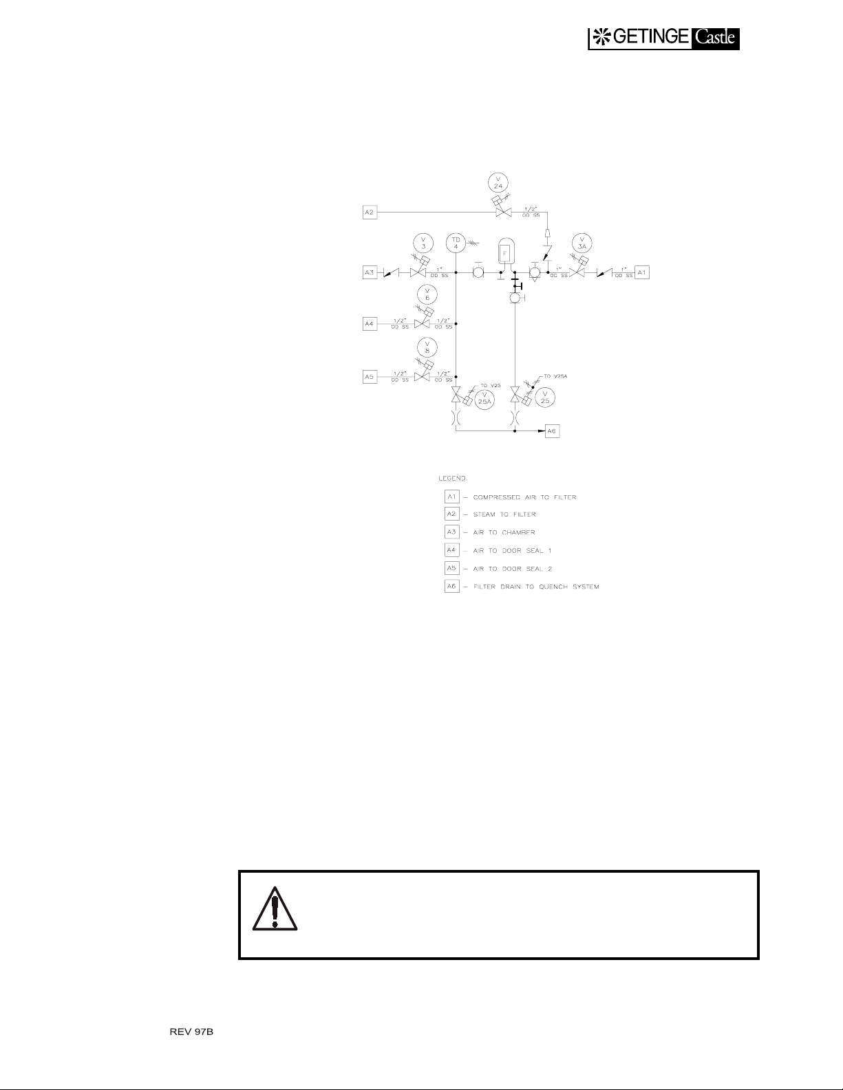
Air filter sterilization program.
The sterilizer is equipped with a program for automatic in-line sterilization of the air filt e r .
EXIT MANUAL
1. Val ves 3, 3A, 6 & 8 will clo se, and va lves 24 , 25 & 25A ope n. The
filter housing will be depressurized.
2. By operating valve 24, the system will be sterilized at 121
minutes. This is monitored by a resistive temperature detector,
TD4.
3. Af ter sterilization the system wil l be cooled down. Thi s i s d on e b y
closing valve 24 an d op e ni ng valve 3A letting the co mpressed air
cool the filter. Valves 25 and 25A remai n open to enhance the drying. The drying cycle runs for 10 minutes.
Prior to removal of filter housing, internal pressure of the filter hous ing and piping must be relieved.
o
C for 15
2.5

Service
Spare parts
EXIT MANUAL
Contact your local Getinge representative
or
Getinge/Castle, Inc.
Scientific Division
Service Department
Phone: 1-732-370-8800 Ext. 214
Fax: 1-732-367-7994
Contact your local Getinge representative
or
Getinge/Castle, Inc.
Scientific Division
Parts Department
Phone: 1-732-370-8666
Fax: 1-732-367-7994
2.6
Suggested Preventative Maintenance Schedule
QUARTERLY VIS IT:
1st 2nd 3rd 4th
EXIT MANUAL
Check door Reversal safety
operation
Check door limit switches [ ][ ][ ][ ]
Test 2 PSI chamber safety
switch
Check & adjust doors to
appropriate door gap
Check door seal regulator at
28 PSIG
Check chamber temperature at
sterilization +/- 0.5
Check pressure transducer for
correct readings and linear ity
Test gauges +/- 2 PSI (+/- 1
GMP)
Test vacuum pump operation
& lubricate if applicabl e
o
C
[ ] [ ] [ ] [ ]
[ ] [ ] [ ] [ ]
[ ]
[ ] [ ]
[ ][ ][ ][ ]
[ ] [ ]
[ ][ ][ ][ ]
[ ] [ ] [ ] [ ]
Relubricate & rotate door
seals
Replace door seals [ ] [ ]
Test that safety valves lift at
rated pressure
Adjust main compressed air
regulator filter to 80 PSIG
Adjust door motor air regula-
tor to 25 PSIG
Clean strainers [ ] [ ] [ ] [ ]
Check steam traps for leakage.
Clean or replace if necessary
Check air admit filter for
blockage (Non-biological test)
Change air admit filter [ ]
[ ][ ][ ][ ]
[ ] [ ] [ ] [ ]
[ ][ ][ ][ ]
[ ][ ][ ][ ]
[ ] [ ] [ ]
[ ] [ ]
2.7
Suggested Preventative Maintenance Schedule Continued:
QUARTERLY VIS IT:
1st 2nd 3rd 4th
Check retraction of door seal [ ] [ ] [ ] [ ]
Verify Controls:
A. Check exposure /dry time rs [ ] [ ]
EXIT MANUAL
B. Check all lamps and buttons
C. Check operation of load
probes
D. Verify abort routine and
Emergency stop activation
E. Verify program settings [ ] [ ] [ ] [ ]
Check valve operations/out-
puts
Test operation of cycles in
accordance with program
combination sheet
Check & adjust alignment of
loading equipment
Perform chamber vacuum lead
test (HV units: <1”/hr or .035
BAR/hr)
Check dip switch settings on
mircoprocessors, printers
[ ] [ ] [ ] [ ]
[ ][ ][ ][ ]
[ ] [ ] [ ] [ ]
[] [ ] [ ] [ ]
[ ] [ ]
[ ] [ ]
[ ]
[]
Check all cable & wire connection
Check for plumbing leaks [ ] [ ] [ ] [ ]
Polish exterior stainless panels [ ] [ ] [ ] [ ]
Check operation of utility
switches if equipped
[ ] [ ] [ ] [ ]
[ ][ ][ ][ ]
2.8
3. GENERAL ADVICE
Manual interference in the sterilizing process
When an error like supply medium o r component failure occurs dur ing
a sterilizing process, the process may , after an alarm is emitted, get
stuck in a phase from which the con trol unit can not go further.
The operator can, in some cases, restart the process by pressing the start/
restart button. If this isn 't po ssible or doesn't so lve the alarm, a tr ained
technician must override the buil t in safety condi tions by manu al stepping.
Manual stepping with key switch
EXIT MANUAL
When stepping forward in a process program by means of the button C/
F9 after setting the key switch, all parameters are controlled by the automatic control unit whereby no dangerous situations can occur. The manually stepping means that the proce ss goes from one process phase to
another without time, temperature or pressure conditions being fulfilled.
For safety reasons, the possi bility t o go past a co oling p hase or a pressure equalization is blocked , except in some cases when a fault with an
analog transducer has occurred . Stepping should preferably be carri ed
out with the process still in alarm phase and befo re restarting the process.
When stepping past a cooling phase or a pressure equalization, there no longer exists any blockages to prevent
dangerous situations from arising. The technician himself
has to decide which steps are to be taken.
The manual stepping must only be used by a technician
who is well acquainted with the process, the properties of
the sterilized goods and the function of the individual ster ilizer components.
3.1

Fault with an analog transducer
Fault with an analog pressure t ransducer or temperat ure sens or stops a
proceeding process. In case of a pr essure transd ucer fault , the operato r
therefore has to step past the pressure conditions at post vacuum, evacuation, natural cooling and pressure equalization. With temperature
sensor fault the operator has to step past the corresponding temperature
conditions.
Fault with an analog pressur e transduce r or temperat ure sensor is indi cated only once per process by th e control unit.
Pressure transducer fault
Program with post vacuum.
Step to the post vacuum phase.
•
(NOTE! The process will perform a normal post vacuum. If a ramp
is needed it has to be cont rolled by manually operating the vacuum
valve.)
EXIT MANUAL
When a required vacuum is reached, step to the pressure equalization
•
phase.
Raise the chamber pressure to atmospheric pressure by opening the
•
valve to the air-in filter or the valve for support pressure. (Refer to
Solenoid Block in COMPONENTS SECTION) Check the chamber
pressure gauge.
Step past the pressure equalization phase.
•
(NOTE! possible only w ith pressure transducer fault)
Program with cooling
Step to the coolin g phase.
•
Restart the process.
•
Control the chamber pressure, by manually operating the solenoid
•
valve for support pressu re. When the load is cooled down, the process will automatically go to pressure equalization phase.
Pressure equalize the chamber to atmospheric pressure by manually
•
operating the soleno id valve controlling the Fast Exha ust drain
valve. (Refer to Soleno id Block in Components Section) Check the
chamber pressure gauge
Step past the pressure equalization phase.
•
(NOTE! possible only w ith pressure transducer fault).
Temperature Sensor fault
The process can be restarted if only one of the load sensors is bro ken.
The process will then disregard the faulty sensor and go on from the
point where the fault occurred.
3.2
EXIT MANUAL
Follow the instructions below if there is only one load sensor or more
than one is fault y.
Program with post vacuum
•
Step to the post vacuum phase.
•
Restart the process.
•
The process will be automatically ended.
Program with cooling
•
Step to the coolin g phase.
•
Restart the process.
•
Make sure that the load has been cooled down to a safe temperature
when the minimum cooling time has expired.
•
Step past the cooling phase
(NOTE! possible only w ith pressure transducer fault)
•
The process will end automatically.
Sensor fault, independent system
In case the process is sto pped in a co oling or do or opening phase, due
to failure of the independent sensors, the safety system can be by-passed
by manual operation of the safety relays.
See the electric wiring diagram.
Manual control by actuating the control valves
Manual actuating of control valves can be done when a system error
occurs which keeps the process stuck in one phase.
When using this method, there no longer exists any blockages to prevent dangerous situations from arising. The
technician himself has to decide which steps are to be
taken.
The above captioned method must only be used by a tec hnician who is well acquainted with the process, the properties of the sterilized goods and the function of the
individual sterilizer components.
3.3

Open the door manually
The following, important steps, have to be taken into consideration before a door is manually opened
1. Make sure, beyond all doubts, that the valve you are going to
manipulate is the correct one.
2. Drain the chamber from liquid s that might flow out when opening
a door by manually opening a drain valve
3. Relieve pressure from the chamber by manually opening a drain
valve.
4. If sterilizer load consists of liquids, make sure that the temperature
of the liquid is well below its boiling point.
Calibration
Analog sensors/transducers must be calibrated, for example when
replaced.
EXIT MANUAL
When using an oil bath, note the following points:
A Accuracy must meet the specified requirements.
B Compounds or condensation in the oil may cause coatings and thus
severely reduced the accuracy of measurement. Change the oil at
regular interva ls!
C Use an oil bath with a large capacity, preferably more than five
litres.
D Allow the measuring instru ment to stabilize for one to two hours
after the bath has reached the set temperature.
E Allow the oil bath to stabil ize for at least 30 minutes after the sen-
sors are lowered into the bath and the bath has regained its set temperature.
F Clean the sensors thorou ghly to remove the oil after calibration.
See the calibration menus section in the CONTROL UNIT chapter.
3.4
4. THE DOOR
General
The opening and closing motion of the door is executed by a pneumatic
cylinder. As a safety measure there is a squeeze protection integrated in
the top of the door.
When the door is closed, a mechanical lock will bl ock the door. This
lock activates a switch which makes it possible to pressurize the groove
behind the door seal.
The doors are kept c losed by the automat ic control unit and the above
mentioned lock while cycl es are in progress and also when su pply
media fail. The doors do not open until the condition chamber pressure
= atmospheric pressure is fulfilled, not even in case o f an electric failure causing an opening command.
EXIT MANUAL
The door closing system comprises a number of parts and
components which cooperate in a tested, safe way from
personnel and material point of view. These items must not
be subject to violence or improper influence of any kind
which alter their initial function.
Adjustments on doors and associated equipment must be
made by authorized personnel only.
Seal between door and chamber
The door seal is a continuous, thick-walled silicon rubber tube, movable
in a groove and pushed ag ainst the door by means of steam, gas or air
pressure. To enable for the door to move freely, the sealing tube can be
sucked back from the door surface int o its groove by a vacuum device.
Media to chamber
Before entering media to the chamber, all following requirement s have
to be fulfilled:
A Emergency stop not activated.
B Doors are closed.
C The door seals are pressurized.
4.1
D The control system gives signals for operating the media valves.
Adjusting the door motion
The door speed is controlled by a variable restriction in the air line supplying the door cylinder with compressed air. Changing the closing
speed will result in a correspo nding influence on the openin g speed.
1. Adjust the restriction so that the door will close in about 15-18 sec-
onds.
2. Check that the motion is even and free from je rks.
3. Check that the door does not scrape against closely situated metal
components. Advise for corrections are given under the head line
”Adjusting the door position”.
EXIT MANUAL
Adjusting the door position
A. VERTICALLY
This adjustment becomes n ecessary if the d istance between t he top of
the open door and the ch amber bottom is not = 10 mm.
1. Measure the door adjustment required.
2. Lift away the door covering lower front plate after removing its two
screws near the floor (see chapter INSTA LLATI ON).
3. Close the door by activating its pilot valve by hand.
4. Lower and prop up the door until it rests upon the prop.
Make sure the door is resting securely on the prop!
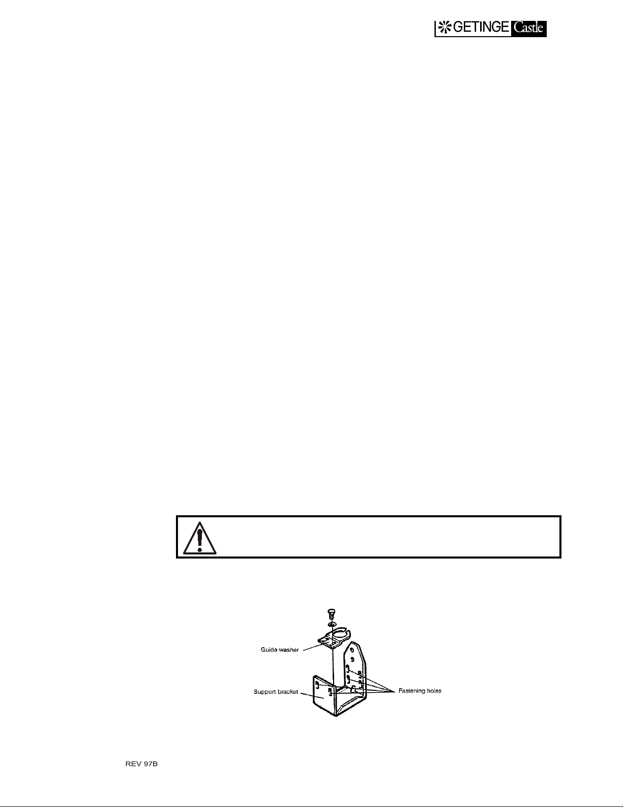
5. Loosen the support bracket, adjust it in accordanc e with th e mea-
sured requirements and tighten the screws.
4.2
B. SIDEWAYS
EXIT MANUAL
6. Pressurize the cylinder, remove the prop and lower the door. Check
the level in rela ti on to the sterilizer bo tt om.
7. Check that the closed door covers the door seal groove completely
(small piston stroke margins).
8. Check that the upper end of the door is horizontal. When needed,
move the lower end of the cylinder piston sideways after the attachment screws of the guide washer has been loosene d. Tigh ten the
screws when the washer is in correct position.
9. Assemble dismantled parts.
10. Remove the front plates as described in the INSTALLATION chap-
ter under the headline Transportation.
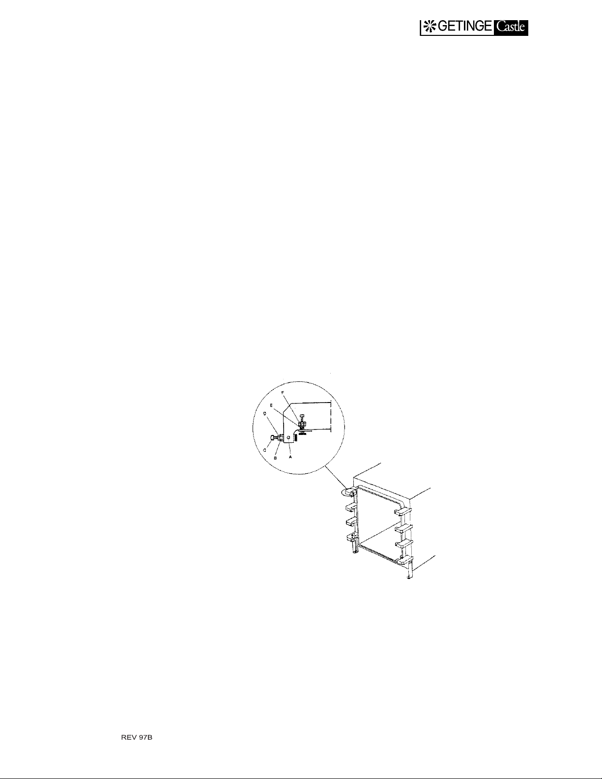
1. Partly loosen the side guide attachment nut F.
2. Adjust the door sideways by means of the screws E so as to form a
clearance space to the guides of 23 mm.
3. The door should be symmetrically located in front of the chamber
opening with the small deviations required for clearance to the trim
plates.
4. Fasten the side guides upon completed adjustment.
C. AXIALLY
1. The clearance space between the door surface and th e door seal
groove should be about 2.5 mm.
2. Remove the front plates as described in the INSTALLATION
chapter under the headline Transportation.
4.3
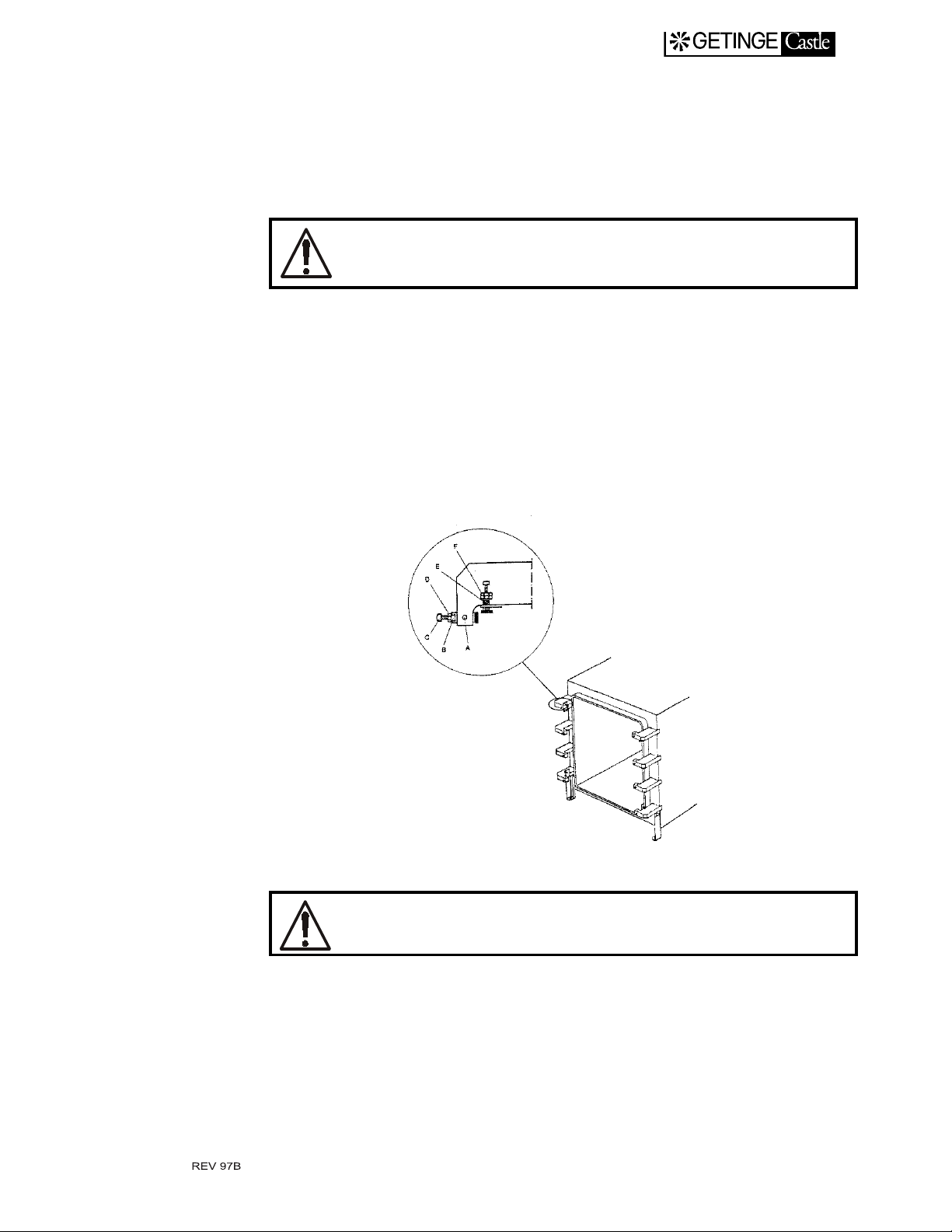
3. Partly loosen the locking screws A and the locking nut D.
4. If needed, loosen the screws B and insert a 2.5 mm thick plate strip
5. Adjust B until the plate strips are squeezed lightly between door
All screws have to be firmly tightened. The screws are an
integrated part of the pressure vessel.
6. Tighten A and D.
7. Remove the plate strips.
Removing the door
1. Remove the lower front panel and both side front panels.
EXIT MANUAL
between door and seal groove at each corner.
and seal groove.
2. Place a prop or similar to stop the door about 150 mm from its end
position when lowered .
Make sure the door is resting securely on the prop!
3. Lower the door.
4. Remove the air hose fitting from the foot of the piston end.
5. Loosen the eight nuts D and remove the screws C together with the
two brass guides.
4.4

EXIT MANUAL
6. Lean the top of the door away from the sterilizer and lift it out. The
weight of the doo r is approx. 75 kg (165 lb).
4.5
The door seal
Care
EXIT MANUAL
The door seal is that part of the pr essure v essel tha t is mo st expo sed to
wear and tear. The comp osit ion o f th e mate ri al, the d esign o f th e seal ,
its fitting and care are of extreme importance for reliable operation and
long life of the seal. Getinge's d oor seal consists of a special silicone
material, and its physical design is intended to make best use of its special characteristics.
Use only genuine Getinge door seals. Remember that each
seal is an integral part of the pressure vessel.
There are several negative factors that adversely affect the life of the
door seal. By avoiding them as far as possible, the life of the seal can
be considerably extend ed.
Avoid leaving the sterilizer switched on in the standby mode during
•
the night. Al though th e door seal materia l can with stand co ntinuou s
temperatures of more than 200 °C, it slowl y d egrades where it is in
contact with the seal groove. Leaving the ster ilizer continuously
energized will shorten the life of the seal by about 60 %.
If the sterilizer has a steam generator, the generator must be drained
•
at the prescribed interval s. Any feed water other than de-i onised
feed water will gradually build up a concentration of mine r a ls and
other substances. At high concentrat ions, several of t hese substances
are carried over with the steam and precipitated on the seal as weak
acids.
If the sterilizer is connected to a central steam system, the quality of
•
the steam is decisive in determining the life of the seal. Chemicals
are often added to the feed water for such purposes as protecting
pipes against corrosion. Undesirable chemical characteristics of the
steam include high hyd razine or carbon dioxide contents.
Keep the seal lubricating layer intact and the sealing groove clean.
•
The lubricating layer not only assists the seal in sliding, but is also an
effective barrier again s t long-term chemical breakdo wn. See also
under the 'Lubrication of the door seal' heading.
Lubricating the door seal
At delivery the door seal is prepa red wi th a dr y lu bric ant wh ich resu lt s
in a graphite grey appearance. The lubricating film has to be renewed in
order to maintain the safe function of the seal. Renewal of the lubricating layer must not be made with the seal in place. Repeated spraying in
4.6
EXIT MANUAL
the groove will build u p layers which ev entually wil l cause t he gasket
to leak.
Disconnect the air supply or similar to make it impossible
for the door to close while the work is carried out.
When applicable, see also chapter ”Special advice for sterilizer with
automatic loader”.
•
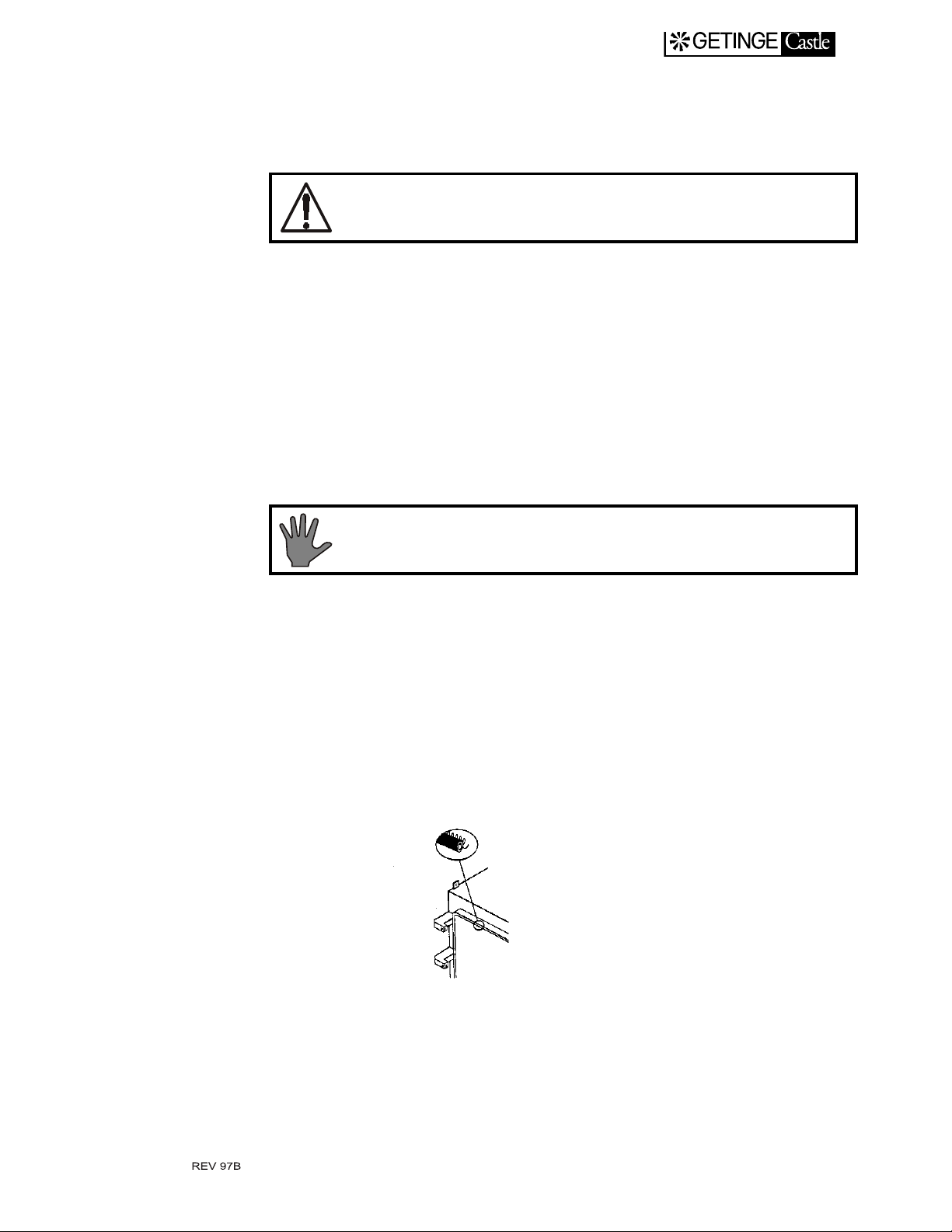
Remove one of the safety plate screws and push the plate towards the
empty screw hole until it becomes free at the opposite end (Vertical
door system only).
•
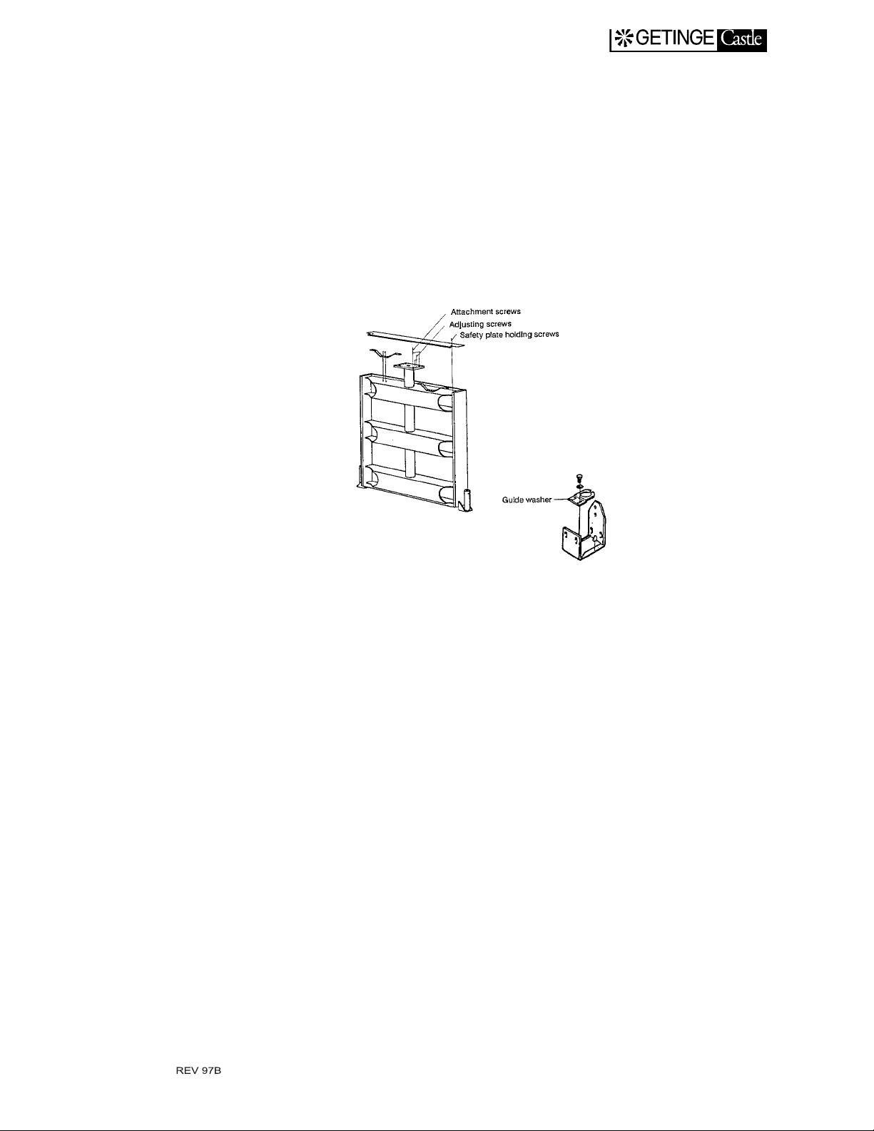
By means of a 6 mm allen-key, loosen the four cylinder attachment
screws six turns each (Vertical Door System Only).
CAUTION! Do not tamper with the four smaller screws
which have now become loose.
•
Remove the gasket from the groove. Be careful with gasket and
groove.
•
Clean the groove of anyth ing that may interfere with subsequent
sealing.
•
Clean the gasket with alco hol until its surface is felt absolut e ly
smooth.
•
Spray the gasket all over with dry lubricant, Dow Corning Molykote
321 recommended.
•
Check that the helix is in place at the bottom of the groove.
4.7
•
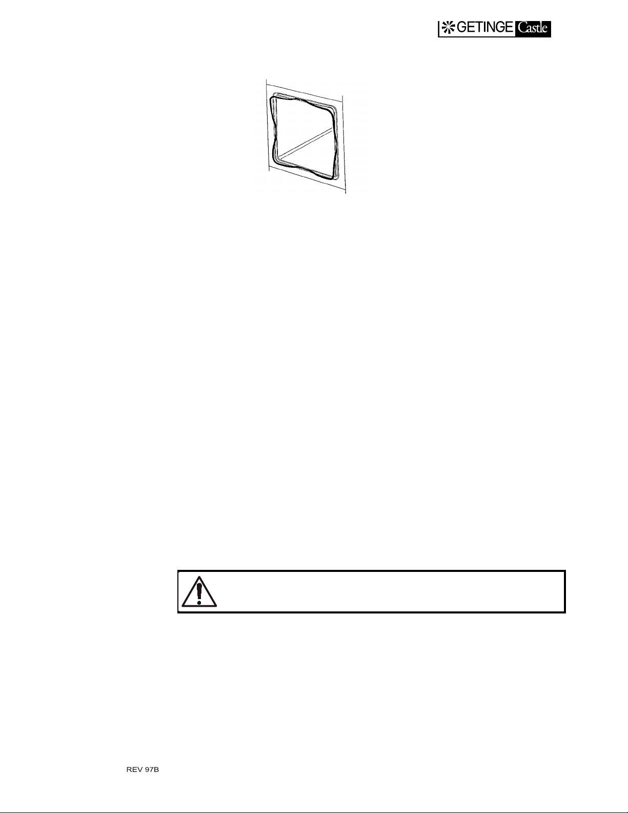
Press the gasket joint into the middle of the upper horizontal part of
the groove.
•
Press the middle of the gasket loop into the middle of the lower horizontal part of th e groove and finally th e middle of the two rem aining
loops into the middle of the vertical parts of the groove.
•
Push the gasket into th e groove. Alwa ys work towards th e corners to
make these collect the excess length of the gasket.
•
Tighten the four cylind er attachment screws.
•
Fit the safety plate by pushing it to the side with the missing screw,
press it down and hook it up at the opposite end. Tighten the fixing
screw and check the function.
EXIT MANUAL
Replacing the door seal
Proceed as describe d under Lubricating the door seal bu t skip se ction s
concerning cleani ng seal and spraying seal.
Replacing the door cylinder
1. Close the door by operating its air solenoid valve by hand.
2. Place a prop or similar to stop the door about 150 mm from its end
position when lowered manu a l.
Beware of the danger of insufficient support
3. Remove the cylinder air hose fitting located on the piston stand and
remove prop to comple tely lower the door.
4. Remo ve one of the safety plate atta c hment screws and push the
plate towards the empty screw hole until it loosens at the opposite
end.
5. By means of a 6 mm allen-key, remove the four cylinder attachment
screws.
4.8
EXIT MANUAL
6. Prevent the piston from moving out of the cylinder by keepin g the
safety valve at its bottom closed (pull ed out). Lift away the cylinder.
7. Attach the nipple and hose to the piston of the new cylinder.
8. Fit the cylinder into the door . Prevent the piston from m oving out
of the cylinder as described ea rlier or with a piece of string.
9. Attach it by means of the four allen-screws. With the four adjusting
screws, make the cylinder align with the center line of the notches
of the stiffening bars.
10. Attach the piston end guide washer in that position which makes the
door move in the most proper way.
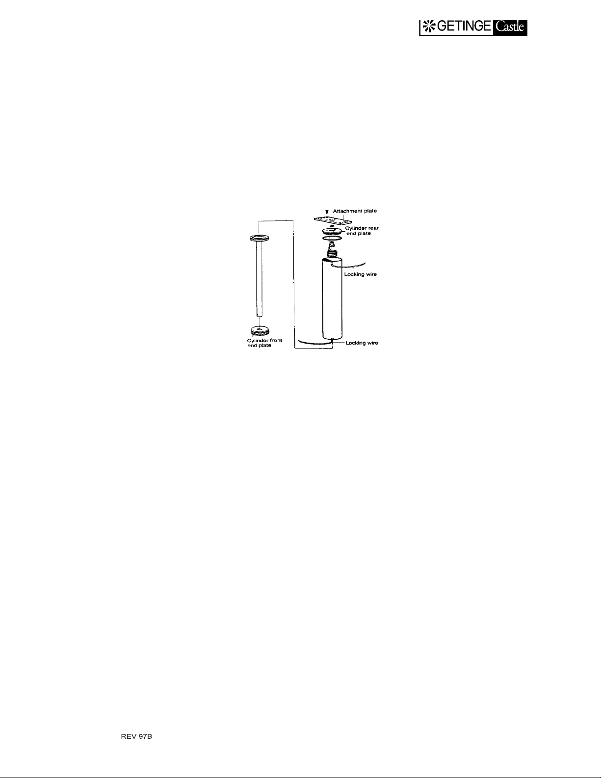
Replacing the piston seal
A worn-out piston seal can not be replaced as separate unit but the
whole piston has to be replaced.
First perform ”Replacement of door cylinder”, section 1-7.
1. Fix the cylinder carefully in a v ice jaw.
2. Remove the cylinder attachment plate.
3. Twist the cylinder end plate until the end of the locking wire
appears in the locking wir e hole.
4. Twist the cylinder end plate in that directi on which feeds the lock-
ing wire out of the hole. The wire may need help from a tool to ent er
the edge of the hole.
5. Pull out the bent end of the locking wire from its driver hole.
6. Remove the cylinder end plate and replace its O-ring in connection
with the replacement of the piston even if it appears to be free from
damage.
7. Push out the piston and fix it in a vi ce jaw.
4.9
EXIT MANUAL
8. Protect the piston rod from tool marks with a piece of weak plate
around its lower part, whi ch is stiffened up by an insert piece of
brass, while gripping there, but no whe re el se, with a pipe wrench
or similar tool.
9. Twist the piston rod to thread off. If sticky, apply heat carefully to
soften the thread sealing compound. Clean the piston rod thread s
with a wire brush.
10. Apply ”Lo c ti t e 54 2" hy dr a ul ic seal ing compound on the threads
and screw the new piston on to the piston rod.
11. Assemble the cylinder and install it according to the points 8-11
under the head line ”Replacing the door cylinder”.
Door safety arrangements
Squeeze protection
The door motion is executed by a pneumatic cylinder the air inlet of
which is considerably choked. An air exhaust valve having much larger
flow capacity is arranged at the free cylinder end which is directed
upwards. Any obstruction present during door closing exerts pressure
on a plate running the entire length of the upper edge of the door at
which this plate makes t he exhaust valve open, thereby s topping the
upward motion immedi ately. This will preven t personnel injuries an d
material damage.
Safety check
The safety check shall be performed in the early stage of the door closing operation. This reduces the risk for injuries due to squeezing.
1. Check that the air supply pressure is maximum perm issible 8 bar
(100 PSIG).
2. Open the door speed control valve entire ly.
4.10

3. Close manually the door cylinder exhaust valve and open the inlet
valve to make the door close.
4. Push downwards by hand and check that the plate moves freely.
This enables the valve to open for a force on any spot of the plate
without use of extreme force.
Blocking the start and opening the door
To prevent the door from opening by its own weight in case the pneumatic door cylinder sho uld become depressurized, a brace underneath
the door keeps it in closed position. The brace is brought in the stop
position under the door by spring-force 20 seconds after a door closing
command has been given. A limit switch senses the position of the brace
thereby stoppi ng the process from b eing started and medi ums being
admitted to the chamber before the door is compl etely closed.
EXIT MANUAL
Safety check
1. Check that the air pressure is minimum permissible 6 bar (80
PSIG).
2. Admit compressed air to make the door close.
a
3. Check that the measurement ”a” is 3-4 mm.
Adjust the height of the brace when needed.
4. Check that the end of the brace is well within the cylinder circum-
ference. (”b” = 12-17 mm)
b
5. Check by listening that the contact of the limi t switch does not
change over until the brace is sa fely under the pneumatic cyli nder.
Beware of the danger of squeezing, while manipulating the
brace.
4.11

6. Check that the retaining pin is in place, preventing the limit switch
operating cone from moving on th e thread.
7. Operate the brace cylinder air valve repeatedly to che ck that the
motion of the piston is smooth an d free from jerks.
8. Check while the door is moving that it stops and remains stopped
when pushing the EMERGENCY STOP-button.
Safety check, door seal groove pressure switch
A pressure switch senses the pressure in the seal groove and breaks the
connection with those valves which control the admittance of steam,
compressed air, water and gases whenever the seal groove pressure falls
below the set point.
For double door sterilizers there are always two pressure switches,
one for each door.
•
Check the P&I diagram to identify and the pressure switch(es) for the
door seal groove(s).
EXIT MANUAL
•
Start a process.
•
Stop the process using the main power switch, when full pressure is
reached in the seal groove.
•
Connect a measuring device (Ohm-meter) over the connection points
of the pressure switch.
•
Keep the sterilizer main power switch switched off. Due to condensation of steam, the pressure in the groove will decrease.
•
Note the pressure at which con tact change-over takes place. Right
value shall be 1.9 bar(g) ± 0.1 (28 PSI).
•
After the check, disconnect the measuring device.
•
Switch the main power on and end the process (See section Alarm in
OPERATION Chapter in the Service Manual).
Emergency stop button
When the emergency stop button is activated , the following fun ctions
are blocked:
•
Media to chamber.
•
Air supply for open ing and closing door.
4.12

Safety check
EXIT MANUAL
Further, the control system will enter the alarm phase.
A Open a door. While the door is moving, press the em ergency stop
button. The door shall stop and the contr ol system give an alarm.
Reset the alarm and reset the emergency stop button. Open the door
by pressing the ”open door” button.
B Close the door and start a sterilizing cycle.
C Press the emergency stop button when steam is entering the cham-
ber. The steam valve shall close and the system shall go i nto the
alarm phase. The printer (if connected) prin ts ”Process Stop” and
the stop is indicated on the display of the co ntrol system.
D Reset the alarm and reset the emergency stop button.
E End the sterilization cycle.
In case above described functions do not work according
to the description, let a well trained technician check the
system.
F Make above safety check also for emergency stop button at the sec-
ond door.
4.13

EXIT MANUAL
5. CONTROL UNIT - ALLEN BRADLEY
The object of the control system is to produce command s and transmit
information to the sterilizer componen ts enabli ng for a number of sterilization processes to be accompli shed in accordance with a predicted
pattern. The command signals are generated by the control unit computer program in combination with measurements of the process parameter values. The latter consist mainly of times, temperatures and
pressures.
Various equipment can be connected to the control unit for programming, monitoring and recording the sterilization processes.
The operator communicates with the control unit via a control panel.
The entire process is controlled by an Allen Bradley SLC 504 microprocessor control system.
The Allen Bradley SLC 504 control system is made up of the Control
Processing Unit (CPU) and a Panelview504 Operator Interface Panel.
This panel contains status indi cator ligh ts and display while servi ng as
the operator interface for cy cle selection and cycle parameter inp ut.
Visual indication of the process appears as a read-out on the display.
Documentation of programs, system definitions and process data can be
made by connecting a pri nter. A host computer can also be connected
direct to the control unit CPU.
The computer contains a program section for calibration of temperature
and pressure transducers. Correction constants, when known, may be
entered manually. Among available test functions there are facilities for
activating analog and digital outputs and monitoring analog and digital
inputs. The maximum programmable digits are 9999.
The hardware of the steri lizer control system contains the operating
panels easily locate in a suitable place. The CPU and po wer pack are
placed in a separate electrical enclosure, connected to the operating panels.
Some terms of the branch
STERILIZATION means the whole series of treatments to form a process in order to attain total killing of all viable organisms. This is in connection with autoclaves usually made up by air removal, heat treatment
and a drying phase.
STERILIZING means the actual killin g part, th e heat treatmen t, of the
total process.
Analogous to the two expressions above, STERILIZATION TIME
means the durability of the total process from the start until the goods
can be unloaded. PROCESS TIME is equal to sterilization time.
5.14

EXIT MANUAL
STERILIZING TIME represents that part of the process on ly during
which the programmed STERILIZING TEMPERATURE prevails in
the chamber.
PARAMETER in this context means the ELEMENTS WHICH
INFLUENCE the sterilization course. Examples of parameters in the
sterilization process are temperature, pressure, time, gas concentration,
etc. The PARAMETER VALUES may be fixed in the program or operator adjustable.
F
-VALUE is a time defined by the equ ation
0
t
T
k1–
t
()
------------------k
2
F
10
=
∫
0
0
t = Time in minutes
×
dt
T(t) =
= Constant within the range 0.0 - 150.0 oC. Usually 121.1 oC
k
1
= Constant withi n the range 0.0 - 99.9 oC. Usually 10.0 oC
k
2
The F
Load temperature at time t
. value is based upon the sterilizing time, required for the temper-
0
ature prevailing in each moment, being recalculated to the base temperature for steam sterilization, 121.1
The use of F
value is most common in the pharmaceutical field, where
0
often the time control of sterilization processes is based upon this value,
thereby utilizing t he heat appl ied du ring heat ing u p and cooli ng down .
By this method, heat sensitive products do not need to be exposed to
high temperatures for a longer period of time than required in obtaining
a sterile result.
Operating panel SLC 504
By means of the SLC 504, the operator selects program, alter parameter
values, starts and monitors the processes and receives information about
possible errors occurring with the sterilizer.
o
C
5.15

EXIT MANUAL
The SLC 504 control p an el will not allow for su ch programming of the
cycle, such as making new processes or altering programs already resident in the CPU.
Display
Front Panel
Rear Panel
The 256 x 128 pixel displa y is the liqu id cryst al type. The back light i s
field replaceable to extend the life of the terminal.
The SLC 504 control panel consists of multiple touch keys for operator
interface.
•
Numeric keypad with decimal and underline.
•
Function keys for F1 through F10 selection.
•
Scroll arrow keys to move the cursor left or right
down
ÏÐ
.
•
ENTER key
•
Backspace key
The back of the SLC 504 cont rol panel c ontains tw o I/O Termina l Ports.
↵
.
Í
ÍÎ
and up or
•
Remote I/O port to connect a remote I/O Network.
•
RS-232 port al lowing c onnecti on to a R S-232 port of a comp uter for
information transfer .
5.16

Push Buttons/Indicator Lights - Load Side
EXIT MANUAL
Emergency
Stop/ Abort
Alarm
Acknowledge
Control Power
ON/OFF
This push button is used to discontinue a
cycle. Once depressed, the outputs of the
control system will be turned off disabling
the sterilizer. At this time, a key must be
used to unlock the emergency stop button.
To unlock the emergency stop, turn the
key. The button will m ove outward to
reset. The operator must then acknowledge the alarm via the function keys
located on the Allen Bradley display.
This push button is pressed to acknowledge any alarm prior to continuing or
aborting a cycle. This push button is also
used to acknowledge that the sterilizer is
unloaded after closing the door on the
unload side.
This selector switch controls power to the
OFF position, all digital outputs are turned
off disabling the sterilizer. During normal
operation, the switch should be in the ON
position.
Open Door This push button is used to open the steril-
izer door after a cycle has ended. When
illuminated, it signals to the operator that
the door can be opened.
Close Door
This push button is used to close the door.
It must be pressed and held the entire time
that the door is in motion. The door will
reverse to the open position if the button is
not held.
5.17

Push Buttons/Indicator Lights - Unload Side
EXIT MANUAL
Emergency
Stop/ Abort
Alarm
Acknowledge
Open Door
Close Door This push button is used to close the door.
This push button is used to discontinue a
cycle. Once depressed, the outputs of the
control system will be turned off disabling
the sterilizer. At this time, a key must be
used to unlock the emergency stop button.
To unlock the emergency stop, turn the
key. The button will m ove outward to
reset. The operator must then acknowledge the alarm via the function keys
located on the Allen Bradley display.
This push button is pressed to acknowledge any alarm prior to continuing or
aborting a cycle. This push button is also
used to acknowledge that the sterilizer is
unloaded after closing the door on the
unload side.
This push button is used to open the sterilizer door after a cycle has ended. When
illuminated, it signals to the operator that
the door can be opened.
It must be pressed and held the entire time
that the door is in motion. The door will
reverse to the open position if the button is
not held.
Cycle In
Progress
This indicator light iden tifies the cycle is
in progress.
5.18

Passwords
EXIT MANUAL
Six passwords exist in the Allen Bradley and consists of five digits 0000
- 99999. The password sections are:
Parameters
•
Cycle Start
•
Cycle Time & Date
•
Service
•
Calibration
•
Master Password
•
Passwords at delivery:
The passwords set in the con trol system is revealed in a special docu ment delivered in a sealed envelope together with the sterilizer manuals.
Detailed screen displays
Main Menu
Upon start-up of the sterilizer, the main menu of the display will appear
as shown below. Functions such as cycle selection, start cycle, runtime
screen, change cycle parameters, alarms, and service information can be
accessed through the main menu.
Us the up or down arrows located on the panelview keypad to select the
next display frame. Press return to acknowledge and advance to the
selected display frame.
5.19

Load Door Main Screen
EXIT MANUAL
This screen allows for the selection of the Validation Password Screen
to allow the operation of a cycle from the opposite door. The correct
password must be entered for the following displayed on the Unload
Door.
Unload Door Main Screen
5.20

EXIT MANUAL
.
5.21

Cycle Selection/Start Cycle
In the Cycle Selection menu screen, select the type of cycle to be run by
pressing the appropriate function key (F1, F2, etc.). The type of cycle
selected will appear in the highlighted box. Press F5 to start the cycle.
.
EXIT MANUAL
5.22

Cycle Start
EXIT MANUAL
The display will then ask the operator to verify start of the cycle. Press
F3 to acknowledge the start of th e cycle. The sterilizer’s door will then
be sealed and locked initia ting the cycle.
.
Following the selection of F3, the following confirmation screen will
appear:
5.23

Runtime Screen
EXIT MANUAL
The Runtime screen a llo ws th e opera tor to o bserve t he co nd ition s d uring the sterilizer cycle such as temperatur e, pressure, etc. This d isplay
is accessed through the main menu via the up or down arrow keys followed by pressing the return button
.
5.24

Cycle Parameters
EXIT MANUAL
The Change Cycle Parameter d isplay screen is us ed to alter par ameter
setpoints of the cycle to be run such as st erilization time and temper ature. This display is accessed through the main menu. Use the up or
down arrow keys followed by pressing the return key to access this display. A password is req uired to access the Cha nge Parameter display.
Press F1 to enter the password. Enter the password using the numeric
keys followed by pressi ng the return key.
.
Select the cycle in which the parameters are to be altered. Use the up or
down arrow key to select the cycle followed by pressing the return key.
.
5.25

Change Parameter
In the Change Parameter display, the current parameter settings will be
displayed. To alter a pa rame t e r, pr e ss th e app ropriate function ke y ( F1,
F2, etc.). Enter the parameter value using the numeric keys followed by
pressing the return key. Decimal points are not required in en tering the
new value. A cycle may be started from this display screen by pressing
F5.
Textile Cycle:
.
EXIT MANUAL
Insitu Cycle:
.
5.26

Liquid Cycle:
.
EXIT MANUAL
Leak Test Cycle:
.
5.27

Parameter Password Screen
In the Change Password Screen, the operator can set or change the
parameter password. To set or change the parameter password, press
F1. Enter the password by using the numbered keys followed by pressing the return key.
.
EXIT MANUAL
5.28

Alarm Display
EXIT MANUAL
In the event an alarm condition occurs during a cycle, the Alarm display
screen will appea r. The type of alarm will be displayed in the high lighted box. Any al arm or aborte d cycle must be ackn owledged to the
control system. Acknowledge the alarm by pressing F3. The system will
then ask the operator to conti nue the cyc le or abort the cycle. Press F3
to abort the present cycle or F5 to continue the present cycle.
Emergency Stop Alarm Screen:
5.29

System Information
The System Information display screen will identify informa tion about
the cycle progress.
EXIT MANUAL
5.30

Service Screen
EXIT MANUAL
The Service display screen is used for service and maintenance functions such as monitoring control v alue, I/O ch ecks and man ual contr ol
of the sterilizers. The service display screen is accessed through the
main menu by the use of the up or down arrow keys followed by pressing the return key. A service password is required to access the service
display screens. Press F1 to enter the service password. Enter the password by using the numeric keys followed by pressing the return key.
In the Service display screen, the up or down arrow keys are used to
select the sterilizer components to be monitored and/or altered. Press
the return key to access the display screen s for th ese functions.
5.31

Service Screen Passwords
In this display scree, the user can change the service password. To
change the current service password, press F1. Enter the new password
using the numeric keys followed by pressing the RETURN key to enter
the password. The system will then ask the user to verify the password.
Re-enter the password followed by pressing the RETURN key.
EXIT MANUAL
5.32

Digital Inputs
EXIT MANUAL
In the Digital Input display, the user can observe the system’s digital
inputs as they are energized. An illuminated box ind icates that the
device is on and providing input to the controller.
.
5.33

Digital Outputs
EXIT MANUAL
In the Digital Outpu t display, the user can manually overrid e devices,
such as opening valves, once the device is in the manual mode. For each
digital output display, the left-hand column and associated function
keys will place the selected dev ice in the manual mode when pressed.
The right-hand column and associated function keys will physically
turn the devic e on or off when p ressed. A n illumi nated bo x represe nts
the device in ON.
.
5.34

EXIT MANUAL
5.35

EXIT MANUAL
.
5.36

EXIT MANUAL
.
5.37

PID Control
EXIT MANUAL
In either the Jacket PID or the Chamber PID display screen, the user can
observe the operation of the valve which controls steam to the chamber
or jacket. The proportional ga in an d reset valu es used to maint ain temperature control can be altered fr om this display. To alter one of the
parameters, press the appropriate function key. PRess F3 to alter the
PROPORTIONAL GAIN value or F2 to alter the RESET value. Enter
the new value using the numerical keys followed by pressing the
RETURN key to enter the value.
Jacket PID
Chamber PID
5.38

Alarm and System Messages - Troubleshooting
Note:
All alarms and system messages must be acknowledged to silence the
alarm and clear the display. Fatal errors will interru pt the cycle. The
cycle will not be interrupted whe n a non-fatal error occurs. Ackn owledging the error will not interrupt the cycle. When troubleshooting,
ALWAYS refer to the wiring diagram for the unit being serviced. Also
see the Input/Output table in the Appendix.
SERVICE TO BE PERFO RMED BY QUALIFIED PER SONNEL
ONLY.
EXIT MANUAL
5.39

Information Text
The following messages are displayed on the display panel. Typically
the “CYCLE RESTARTED” and “CYCLE ABORTED” messages will
also be printed to the printer
CYCLE ABORT This message will be displayed if, following pu shing
Emergency Stop butt on and then restori ng the power, t he
operator elects to abort the current cycle by pushing the
OPEN DOOR button. S ee Emergency Stop below.
SEALING DOOR #1 This message will be d isplayed on the display panel once
all start conditions are satisfied and the start button is
pressed. When Door #1 is fully sealed, the message is no
longer displayed.
EXIT MANUAL
SEALING DOOR #2 This message will be displayed on ce all start conditions
are satisfied and the Start butt on is pressed. When Door
#2 is fully sealed, the message is no longer display ed.
UNSEALING DOOR #1 During the Cycle End phase, this message will be dis-
played as the Load Door is unsealed.
UNSEALING DOOR #2 During the Cycle End phase, this message will be dis-
played as the Unload Door is unsealed.
CYCLE COMPLETE During the Cycle End phase, this message will be dis-
played after the chamber has returned to atmospheri c
pressure.
CYCLE RESTARTED This message will be displ ayed if, foll owing pu shing th e
Emergency Stop butt on and then restori ng the power, t he
operator elects to continue the cur rent cycle by pushing
the CONTINUE button on the Alarm Display. See Emergency Stop below.
UNLOADING This message will be displayed du ring the Cycle End
phase while the unload door is opened.
PRESS OPEN - LOAD This message will be displayed du ring the Cycle End
phase once the unload door has been closed again following unloading the Load Door may be opened.
OPEN DOOR This message will be displayed du ring the Cycle End
phase once the Load Door seal has been pulled and the
door is ready to be opened.
5.40

Alarm List
EMERGENCY STOP
Message Display:
EMERGENCY STOP
This alarm is activated when the Emergency Stop pushbutton is activated from the fascia panel. All digital outputs except for the alarm and
Acknowledge Alarm lamp will be turned off. The alarm will sound and
the Acknowledge Alarm lamp will flash. It will also activate the emergency stop alarm scr een on the PanelView 9 00 operator terminal . The
alarm will be printed if the unit is in cycle.
Operator Acknowledgement:
Press the Acknowledge Alarm button to silence the alarm. The
Acknowledge Alarm lamp will stop flashing, but remain illuminated.
All outputs remain off.
EXIT MANUAL
The Emergency Stop button must be reset by inserting the key and
twisting in the clockwise direction. The cycle may be aborted or continued by pressing the appropriate button area of the touch screen display.
When a cycle is abor ted, the sterilizer will advance to the post condi tioning phase of the cycle allowing the sterilizer to advance to a safe
condition. When a cycle is continued, the process will return to the condition at the point when the alarm was activated and continue the cycle.
CHAMBER TEMPERATURE SENSOR ERROR
Alarm Condition:
The probe is out of the allowable range of -5.0
Message Display:
CHAMBER TEMP OUT OF RANGE
This alarm will turn off all digital outputs except for the alarm and
Acknowledge Alarm lamp. The alarm will sound and the Acknowledge
Alarm lamp will flash. It will also activate the alarm screen of the PanelView 900. The alarm shall be printed.
Operator Acknowledge:
o
C to 150oC
Press the Acknowledge Alarm button to silence the alarm. The
Acknowledge Alarm l amp will sto p flashi ng a nd r emain illu min ated i f
the alarm condition is still present. All outputs remain off.
The alarm must be cleared by repair or replacement of the defective
component. When the sensor returns to within the allowable range, the
process will return to the co ndition when the alarm was activ ated. The
Alarm Acknowledge lamp will extinguish.
5.41

PRESSURE SENSOR ERROR
Alarm Condition:
The sensor is out of the allowable range of 0 PSIA to 50.0 PSIA.
Message Display:
CHAMBER PRESSURE OUT OF RANGE
This alarm will turn off all digital outputs except for the alarm and
Acknowledge Alarm lamp. The alarm will sound and the Acknowledge
Alarm lamp will flash. It will also activate the alarm screen of the PanelView 900. The alarm shall be printed.
Operator Acknowledge:
Press the Acknowledge Alarm button to silence the alarm. The
Acknowledge Alarm l amp will sto p flashi ng a nd r emain illu min ated i f
the alarm condition is still present. All outputs remain off.
The alarm must be cleared by repair or replacement of the defective
component. When the sensor returns to within the allowable range, the
process will return to the co ndition when the alarm was activ ated. The
Alarm Acknowledge lamp will extinguish.
EXIT MANUAL
INSITU FILTER TEMPERATURE SENSOR ERROR
Alarm Condition:
The probe is out of the allowable range of -5.0
Message Display:
INSITU FILTER TEMP OUT OF RANGE
This alarm will turn off all digital outputs except for the alarm and
Acknowledge Alarm lamp. The alarm will sound and the Acknowledge
Alarm lamp will flash. It will also activate the alarm screen of the PanelView 900. The alarm shall be printed.
Operator Acknowledge:
Press the Acknowledge Alarm button to silence the alarm. The
Acknowledge Alarm l amp will sto p flashi ng a nd r emain illu min ated i f
the alarm condition is still present. All outputs remain off.
The alarm must be cleared by repair or replacement of the defective
component. When the sensor returns to within the allowable range, the
process will return to the co ndition when the alarm was activ ated. The
Alarm Acknowledge lamp will extinguish.
o
C to 150oC
5.42

LOAD TEMPERATURE SENSOR ERROR
Alarm Condition:
The probe is out of the allowable range of -5.0
Message Display:
LOAD TEMP OUT OF RANGE
This alarm will turn off all digital outputs except for the alarm and
Acknowledge Alarm lamp. The alarm will sound and the Acknowledge
Alarm lamp will flash. It will also activate the alarm screen of the PanelView 900. The alarm shall be printed.
Operator Acknowledge:
Press the Acknowledge Alarm button to silence the alarm. The
Acknowledge Alarm l amp will sto p flashi ng a nd r emain illu min ated i f
the alarm condition is still present. All outputs remain off.
The alarm must be cleared by repair or replacement of the defective
component. When the sensor returns to within the allowable range, the
process will return to the co ndition when the alarm was activ ated. The
Alarm Acknowledge lamp will extinguish.
o
C to 150oC
EXIT MANUAL
DOORS NOT CLOSED
Alarm Condition:
The door limit switch input is on.
Message Display:
DOORS NOT CLOSED
This alarm will turn off all digital outputs except for the alarm and
Acknowledge Alarm lamp. The alarm will sound and the Acknowledge
Alarm lamp will flash. It will also activate the alarm screen of the PanelView 900. The alarm shall be printed.
Operator Acknowledge:
Press the Acknowledge Alarm button to silence the alarm. The
Acknowledge Alarm l amp will sto p flashi ng a nd r emain illu min ated i f
the alarm condition is still present. All outputs remain off.
The alarm must be cleared by repair or replacement of the defective
component. When the repai r is complete, the process wi ll return to the
condition when the alarm was activated. The Alarm Acknowledge lamp
will extinguish.
5.43

DOORS NOT SEALED
Alarm Condition:
The door seal pressure switch reads low (off) for mor e than 2 minutes.
Message Display:
DOORS NOT SEALED
The alarm will sound and the Acknowledge Alarm lamp will flash. It
will also activate the alarm screen of the PanelView 900. The alarm
shall be printed.
Operator Acknowledge:
Press the Acknowledge Alarm button to silence the alarm. The
Acknowledge Alarm l amp will sto p flashi ng a nd r emain illu min ated i f
the alarm condition is still present.
Check that required steam pressure is being supplied to the unit. The
alarm must be cleared by repair or replacement of the defective component or providing required steam pressure. When the repair is complete,
the process will return to the condition when the alarm was activated.
The Alarm Acknowledge lamp will extinguish.
EXIT MANUAL
DOORS 1 SEAL LEAK
Alarm Condition:
The door 1 seal flow switch reads high for more that 20 seconds.
Message Display:
DOORS 1 SEAL LEAK
The alarm will sound and the Acknowledge Alarm lamp will flash. It
will also activate the alarm screen of the PanelView 900. The alarm
shall be printed.
Operator Acknowledge:
Press the Acknowledge Alarm button to silence the alarm. The
Acknowledge Alarm l amp will sto p flashi ng a nd r emain illu min ated i f
the alarm condition is still present.
Check that required steam pressure is being supplied to the unit. The
alarm must be cleared by repair or replacement of the defective component or providing required steam pressure. When the repair is complete,
the process will return to the condition when the alarm was activated.
The Alarm Acknowledge lamp will extinguish.
5.44

DOORS 2 SEAL LEAK
Alarm Condition:
The door 2 seal flow switch reads high for more that 20 seconds.
Message Display:
DOORS 2 SEAL LEAK
The alarm will sound and the Acknowledge Alarm lamp will flash. It
will also activate the alarm screen of the PanelView 900. The alarm
shall be printed.
Operator Acknowledge:
Press the Acknowledge Alarm button to silence the alarm. The
Acknowledge Alarm l amp will sto p flashi ng a nd r emain illu min ated i f
the alarm condition is still present.
Check that required steam pressure is being supplied to the unit. The
alarm must be cleared by repair or replacement of the defective component or providing required steam pressure. When the repair is complete,
the process will return to the condition when the alarm was activated.
The Alarm Acknowledge lamp will extinguish.
EXIT MANUAL
POWER FAILURE
Alarm Condition:
The processor detect there has been a loss of power.
Message Display:
POWER FAILURE
The alarm will sound and the Acknowledge Alarm lamp will flash. It
will also activate the alarm screen of the PanelView 900. The alarm
shall be printed.
Operator Acknowledge:
Press the Acknowledge Alarm button to silence the alarm. The
Acknowledge Ala rm lamp wi ll ex ti ng ui sh.
5.45

HIGH CHAMBER PRESSURE
Alarm Condition:
The chamber pressure transducer reads greater than 60 PSIA
Message Display:
HIGH CHAMBER PRESSURE
This alarm will turn off all digital outputs except for the alarm and
Acknowledge Alarm lamp. The alarm will sound and the Acknowledge
Alarm lamp will flash. It will also activate the alarm screen of the PanelView 900. The alarm shall be printed.
Operator Acknowledge:
Press the Acknowledge Alarm button to silence the alarm. The
Acknowledge Alarm l amp will sto p flashi ng a nd r emain illu min ated i f
the alarm condition is still present. All outputs remain off.
The alarm must be cleared by repair or replacement of the defective
component. When the sensor returns to within the allowable range, the
process will return to the co ndition when the alarm was activ ated. The
Alarm Acknowledge lamp will extinguish.
EXIT MANUAL
VACUUM SYSTEM TIMEOUT
Alarm Condition:
The chamber pressure did not achiev e the necessary vacuum level
within 60 minutes.
Message Display:
VACUUM SYSTEM TIMEOUT
The alarm will sound and the Acknowledge Alarm lamp will flash. It
will also activate the alarm screen of the PanelView 900. The alarm
shall be printed.
Operator Acknowledge:
Press the Acknowledge Alarm button to silence the alarm. The
Acknowledge Alarm l amp will sto p flashi ng a nd r emain illu min ated i f
the alarm condition is still present.
The alarm must be cleared by repair or replacement of the defective
component. When the sensor returns to within the allowable range, the
process will return to the co ndition when the alarm was activ ated. The
Alarm Acknowledge lamp will extinguish.
5.46

LOW STERILIZATION TEMPERATURE
Alarm Condition:
The controlling temperature device reads less than one degree C
o
(1.0
C) than the set sterilization temperature for more than 10 seconds.
Message Display:
LOW STERILIZATION TEMPERATURE
The alarm will sound and the Acknowledge Alarm lamp will flash. It
will also activate the alarm screen of the PanelView 900. The alarm
shall be printed.
The sterilization timer is reset t o ze r o (0:00) minutes and t he ti mer will
not restart until the temperature is regained.
Operator Acknowledge:
Press the Acknowledge Alarm button to silence the alarm. The
Acknowledge Alarm l amp will sto p flashi ng a nd r emain illu min ated i f
the alarm condition is still present.
EXIT MANUAL
The alarm will clear when the sensor returns to the set sterilization temperature. The Alarm Acknowledge lamp will extinguish.
HIGH STERILIZATION TEMPERATURE
Alarm Condition:
The controlling temperature device reads more than two degree C
o
(2.0
C) than the set sterilization temperat ure for more than 2 minutes.
Message Display:
HIGH STERILIZATION TEMPERATURE
The alarm will sound and the Acknowledge Alarm lamp will flash. It
will also activate the alarm screen of the PanelView 900. The alarm
shall be printed.
Operator Acknowledge:
Press the Acknowledge Alarm button to silence the alarm. The
Acknowledge Alarm l amp will sto p flashi ng a nd r emain illu min ated i f
the alarm condition is still present.
The alarm will clear when the sensor return s to less than two degrees
above the set sterilization tempera ture. The Alarm Ackno wledge lamp
will extinguish.
5.47

HIGH WATER LEVEL IN DRAIN
Alarm Condition:
The drain high water level switch (LS10) is on for more than 30 seconds
Message Display:
HIGH WATER
The fast exhaust valve shall open to clear the water from the drain.
When the switch detects no water in the drain, the fast exhaust valve
will close.
The alarm will sound and the Acknowledge Alarm lamp will fla sh. It
will also activate the alarm screen of the PanelView 900. The alarm
shall be printed.
Operator Acknowledge:
Press the Acknowledge Alarm button to silence the alarm. The
Acknowledge Alarm l amp will sto p flashi ng a nd r emain illu min ated i f
the alarm condition is still present.
EXIT MANUAL
The alarm will clear when the switch detects no water in the drain. The
Alarm Acknowledge lamp will extinguish.
LEAK TEST FAILURE
Alarm Condition:
The chamber pressure rises above th e allowable leak amount. The
leak amount set point is dete rmi ned by ad ding th e chamber pre ssure at
the start of the leak test to the allow able leak amount.
Message Display:
LEAK TEST FAILURE
The alarm will sound and the Acknowledge Alarm lamp will flash. It
will also activate the alarm screen of the PanelView 900. The alarm
shall be printed and the process will automatically advance to the air
admission phase to end the cycle.
Operator Acknowledge:
Press the Acknowledge Alarm button to silence the alarm. Determine
the cause of the lead and run another lead test cycle.
5.48

INPUT/OUTPUT LIST
EXIT MANUAL
NAME DESIGNATION
DOOR 1 NOT FULL OPEN LS1A I:1/0
DOOR 1 NOT FULL CLOSED LS1B I:1/1
DOOR 1 SAFETY SWITCH OK PS11A I:1/2
DOOR 1 SEALED PS1 I:1/3
DOOR 2 NOT FULL OPEN LS2A I:1/4
DOOR 2 NOT FULL CLOSED LS2B I:1/5
DOOR 2 SAFETY SWITCH OK PS11B I:1/6
DOOR 2 SEALED PS2 I:1/6
CHAMBER PRESSURE SWITCH PS6 I:1/7
RUPTURE DISK FAILURE PS4 I:1/8
EMERGENCY STOP PB4D1 I:1/10
HIGH DRAIN WATER LEVEL LT1 I:1/11
CONDENSER TEMP HIGH TS1 I:1/12
VACUUM PUMP TRIPPED MS3D2 I:1/13
MEMORY
LOCATION
120VAC POWER SUPPLY OK N/A I:1/14
OPEN DOOR PB200 I:2/0
CLOSE DOOR PS201 I:2/1
OPEN DOOR 2 PB202 I:2/2
CLOSE DOOR 2 PB203 I:2/3
ALARM ACKNOWLEDGE PB204 I:2/4
5.49

Technical data
EXIT MANUAL
5.50

EXIT MANUAL
5.51

6. STERILIZER SPECIFICATION
EXIT MANUAL

7. P&I DIAGRAM
EXIT MANUAL

8. ELECTRIC WIRING
EXIT MANUAL

9. INSTALLATION DRAWING
EXIT MANUAL

10. PHASE LIST
EXIT MANUAL

11. COMPONENTS
Illustration on drawings
• Electric wiring diagrams ar e drawn with power off.
• Apparatus and components are illustrated in their basic position.
• Pressure switches are illustrated in the position they take for atmos-
pheric pressure.
• Thermal switches are illustrated in the position they take for room
temperature.
Departure from these ru les are indicated on the diagrams.
EXIT MANUAL
11.1

EXIT MANUAL
Panel-Mounted Thermal Printer, Model PRNTR0001
The Getinge panel printer is a completely maintenance-free thermal
printer, specially developed to withstand the severe conditions associated with front mounting. The thermal paper has been specially developed for the Getinge panel printer in order to withstand particularly
severe requirements in respect of heat resistance, resistance to fading
and permanent documentat ion.
Loading the paper
Use only genuine Getinge paper for the best printout durability.
The thermal paper i s of hi gh quali ty, supp lie d o n 50 m m ( 2”) d iamet er
rolls with a width of 60 mm (2.4”).
Do not replace the paper without being properly grounded.
If not, static electricity can destroy the microprocessor if
you touch it, or any of the connections.
Turn off the cont rol unit power supp ly switch. The prin ter lamp goes
•
out.
Pull the upper edge of the transparent paper collector outwards in
•
order to release it.
Release the bl ac k printer cov er in the same w a y and remove the ol d
•
paper roll.
Load a new roll of paper with the tongue upwards, as shown in Fig-
•
ure 1. This will automatically posit ion the recording side correctly
in the printer.
Position the roll co rrectly, pull out some of it and close the printer
•
cover so that it clicks into position.
Turn on the sterilizer control power supply switch and feed out about
•
10 mm (1/2”) of paper using the paper feed pushbutton on the printer.
Refer to Figure 2. Check that the paper is being fed correctly through
the opening in th e pr inter cover.
Lift the paper collector into position. The p rinter is ready for use.
•
11.2

Operation
Maintenance
•
Data is recorded automatically as the cycle progresses. The steady
red light on th e lower left of the fron t panel in dicates the po wer is on
and the printer is f unctioning normal.
•
When the red light is flashing, a fault is indicated. The typical fault
is when the printer is out of paper. To check the paper , refer to the
Paper Loading section above. If the printer is not out of paper and the
red light continues to fl ash, call for service.
•
To retrieve the printed record at the end of a cycle, depress the feed
button on the lower right front panel. Paper will continue to feed as
long as the button is depressed . W hen desired paper length is
attained, remove the paper utilizing the “tear bar” of printer.
•
In addition to adding paper, the only maintenance required is occasional cleaning of the thermal print head located immediately above
the printer rubber roller. In general, the print head should be cleaned
after every 10 rolls of paper.
EXIT MANUAL
•
To clean the print head, refer to the Loadin g Paper section above.
With the printer door in its horizontal position, locate the print head.
This is a tan colored strip positioned immediately above the r ub ber
roller. Clean the prin t head by swiping several times with a cot ton
swab and isopropyl alcohol or commercially available thermal print
head cleaning pads.
•
Be sure print head is dry before closing the pri nter door and plastic
cover
11.3

Replacement Parts
EXIT MANUAL
11.4

EXIT MANUAL
Fuse Replacement: Please follow these instructions for proper fuse
replacement.
•
Disconnect power from the unit
•
Push in fuse holder and turn to remove for replacement.
•
Once replaced, re-insert fuse holder by pushing in and turning simultaneously.
PART NUMBERS FOR MAJOR COMPONENTS
Description Part Number
PRINTER MECHANISM PRNME0001
PRINTER CIRCUIT BOARD PRNCB0001
TRANSFORMER ASSEMBLY PRNTR0001
LINE FILTER ASSEMBLY PRNFA0001
PRINTER FRONT DOOR PRNDR0001
PLASTIC COVER PRNCO0001
PAPER ROLL PRNPA0001
POWER/FAULT LIGHT PRNLT0001
FEED PUSH BUTTON PRNBU0001
FUSE LAMP, 3AG PRNFU0001
:
11.5

Specification:
EXIT MANUAL
Description Value
NUMBER OF COLUMNS 24,42
THROUGHPUT 240 CPS
BUFFER SIZE 8 / K
PRINT MODE THERMAL DIRECT 192 DPI
PRINT SPEED/SLEW SPEED 1 IN/SEC
PRINT LINE 56 mm
PAPER WIDTH 60 mm
PAPER ROLL SIZE 50 mm
OPERATING TEMPERATURE 0 TO 50 oC
PRINT HEAD LI F E 30 KILOMETERS
Interface Information:
Description Value
SERIAL STANDARD RS-232C
BAUD RATES SELECTABLE 300 OR 9600
DATA FLOW CONTROL
POWER
XON/XOFF OR
BUSY/READY
110V, 50/60Hz, 0.2A
24V, 50/60Hz,0.83A
11.6

Vacuum pump LEM 60
Item No. Voltage Hz Hp
PUMP0039 208/230/460 60 3
The direct on line starter cut out current, should be set to the value given
by the motor data plate.
Sealing water flow: 1 litre (.3 gal)/ 12 sec.
Air is supplied via an adjustab le throttle valve to the pump.
Servicing
The following inst ructions are intende d to as sist all wo rk that requires
the pump to be dismantled.
EXIT MANUAL
15 16 17 18 19
14
13
12
11
570 04 17
0607080910
6 Spacer 4 Pump end cover
7 Mechanical seal 14 Screw
8 Adjustment screw 15 Pump end cover
9 Impeller 16 Guide plate
10 Plug 17 Pump casing
11 Washer 18 Nut
12 Locknut 19 Stud
13 Valv e globe
11.7

Preparation
Dismantling
EXIT MANUAL
Switch off and lock the sterilizer safety swi tch pri or to
working on the sterilizer.
1. Remove all pipes connected to the pump.
2. Mark and remove the motor leads.
3. Loose the pump stand bolts and remove the pump.
1. Stand the pump on the motor fan cage with the shaft in vertical posi-
tion and remove the connection plate attachment screws (14).
2. Separate the connection plate (15) together with the guide plate (16)
from the pump housing (17) by prying in the cen tre-groove with, fo r
instance, a screw driver.
Take care of the plastic globes
(13).
Reassembling
3. Unsc re w th e c ou nt er nut (12 ).
4. Pull off the impeller (9) using either method a or b below, or a com-
bination of these .
a. Unscrew th e adju stment sc rew (8) comple tely o ut of th e shaf t.
b. Remove the motor flang e at tac hme n t scre ws (18 ). With
symmetrically appl ied levers, prying off th e pump housing
(17) so that the latter serves as a puller for the impeller. Use a puller
if needed.
5. Do not use a hammer but press away smoothly the shaft seal sliding
ring (7) in case it has to be replaced.
Prior to reassembling, all parts should be thor oughly cleaned and
inspected. Special attention should be paid to sealing-surfaces with
regard to wear and scratches.
1. Place the pump on the fan cage as when dismantling.
2. Place the movable part of the shaft seal (7) concentrically around
the shaft with the carbon seal ring facing u pw ards.
3. If the shaft seal (7) has been removed, apply soapy water to its rub-
ber edge, turn it with the rubbing surface to wards you and press it
into position manually in the pump housing (17)
4. Fit the pump housing (17). Turn it until its centre is at minimum dis-
tance to the pump stand and ti ghten the screws.
5. Screw home the adjusting screw (8) completely into the shaft and
fit the impeller (9) with washer (11) and nut (12) so as to form a
clearance space of 0.10 - 0.12 mm between the impe ller and the
11.8

guide plate (16). Lock the scr ew wit h the nut (12) without di spl a c ing the axial posit io n of the impeller.
6. Apply a high viscous, semi-drying sealing compound such as Epple
33, Permatex or similar on the sealing surfaces of the pump housing
(17) and the connection end p late (15). Fit the guide plate (16)
including the valve globes (13) and the connection end plate and
tighten the attachment screws (14).
7. Bring, at the fan end, the shaft to rotate and check it for a smooth
noiseless running.
Loosening a seized pump shaft
It has been reported that the shaft of a vacuum or feed water pump due
to the fine clearances may become t oo tight af ter st anding fo r a per iod
without use. The motor will then not ro tate when switched on . In this
case, proceed as follows:
EXIT MANUAL
Switch off mains at the safety switch and lock.
• Remove the fan hood of the pump motor.
• Pry off the fan with two symmetrically applied levers (for example
large screw drivers).
• Protect the shaft with a folded piece of sheet metal when applying a
pipe wrench. Twis t in both directions to loosen.
• If this procedure fails to loose n the shaft then:
• Loosen the screws, holding the pump housing together, about one
turn.
• Make another attempt to loosen the shaft.
• If required, tap careful ly on the loosened housing.
• Tighten the screws, in rotation checking that the shaft is free to
rotate.
Reset the lockable switch an d check by brief manual opera tion of the
contactor that the pump works normally.
11.9

Solenoid valve block
EXIT MANUAL
Protective circuit
3/2-valve
Integral parts
Solenoid valve block
3/2-valve with So le-
noid
Protective circuit/
LED
The 3/2-valve
is equipped with an pneumatic indicator showing white on normally
closed modules and red on normally open ones.
The protective circuit
has a signal light showing power on to the valve block.
The solenoid valve
has a knob with which the valve can be operated manually. The valve is
manually activated in position ”I” while it is operated by the control system in position ”O”
VALTE0010
INDIC0007
Solenoid valve
11.10

Piston valves
EXIT MANUAL
Piston valves are used for various media as shut-off valves or as control
valves with an on/off function. Such valves are normally maintenance-free, and so any maintenance or replacement is determined by
long-term wear or by seal damage.
Wear and tear can give rise to leakage in the actuator seal, the sleeve
•
seals of the stainless steel pipe or in the valve body stem seal.
If the valve is otherwise in good condition, such leakage can be cured
by a renovation set.
Always replace seals, including any face seals in connections when dismantling the valves.
Wear and tear in the valve actuator will give rise to leakage of com-
•
pressed air to the surroundings. Leakage into the valve body and its
media is prevented by a vent hole in the stainless steel guide tube.
Wear and tear of the stainless steel pipe sleeve couplings can give
•
rise to leakage between that part of the valve body that is connected
to the top of the valve stem and the vent ho le in the stainless steel
pipe sleeve.
Depending on how the val ve is connected, such leakage can be
detected by means of a leak test of the sterilizer or by leakage of
media through the hole.
Damage to, or dirt on, the valve body stem seal can cause leakage
•
between the inlet and outlet sides of the valve. If the valve is connected to the sterilizer chamber, th e easiest way to detect such leakage is by means of a leak test of the sterilizer.
Pressurise the actuator with compress ed a ir when rem oving the valve body to replace the st em seal. This will compress the closing spring.
Beware of the risk of injury when removing the valve body
or actuator, as both contain compressed springs.
11.11

PT-100 Sensors (RTD)
Metal parts: Acid proof stainless ste el (AI SI 31 6 or simi l ar).
Operating temperature: 0 - 140°C.
Operating pressure: -1 to +3 bar(e).
Standard: IEC 75 1-1983 Class A, 4 wire unit.
Model Cable Type Conn. Steel tube
Material (* Length Length Dia. Type
CONEQ0132 Silicon- rubber 8 m Single Fig 1 150 mm 3 mm Bended
CONEQ0131 Silicon- rubber 8 m Single Fig 1 150 mm 3 mm Straight
CONEQ0130 PVC 3 m Single Fig 1 120 mm 2.5 mm Bended
CONEQ0134 Silicon- rubber 8 m Double Fig 2 120 mm 3 mm Bended
EXIT MANUAL
CONEQ0133 PVC 2 x 5 m Double Fig 1 120 mm 3 mm Straight
*) Silicon-rubber c ables are desig ned for loca tions insi de the steri lizer
chamber.
PVC-cables are designed for wireing outside the sterilizer chamber
only. (Max. ambient temperature 90°C) .
Soldered plate heat exchangers
The performance of the plate heat exchangers is vital for correct operation of the sterili zer. Poor heat exchanger performance will automatically reduce the vacuum suction performance of the vacuum pump. This
will, in turn, extend pr ocess times or, in the wor st case, cause the process to fail, due to failure to reach the required v acuum conditio ns. In
addition, poor vacuum pump performance can cause drying-out and
thus indirectly overheating of the load, one of the effects of which
would be to put the validation performance of the sterilizer at risk.
11.12

EXIT MANUAL
The plate heat exchangers n ormally require no maintenance, apart
from possibly removing lime about every second year. If the water hardness exceeds 4 °dH, it may b e necessary to clean the heat exchangers
more often.
Blockage by li me generally t ends to obstr uct the cool ing water inlet of
the final heat exchanger first. Inspect ion there wi ll therefore p rovide a
good indication of th e condition of the cooling system. The f inal heat
exchanger is the one from which the discharge from the sterilizer
emerges. Even though the heat exchangers may not be blocked, even
modest deposits of lime can reduce their efficiency, and so regular
cleaning is still recommended.
When they have been cleaned, the heat exchangers sho uld also be
pressure-tested. During normal operation, the pump circuit is under vacuum, while the cooling circuit is pressurised, which would mean that
any leaks would reduce the performance of the vacuum pump. In addition, hygienic aspects must be considered. Pr essure testing will rev eal
any leakage.
Cleaning
A cleaning solution suitable for cleaning lime deposits, but safe for use
in the heat exchanger, shall be utilized.
Clean the heat exchangers as follows:
•
Dismantle the heat exchanger.
•
Read the instructions for using the cleaner and dilute it as instructed.
•
The cleaning solution shoul d b e heat ed to about 135 °F for best
effect. Alternatively, the heat exch anger can be filled with the
cleaner and then heated up.
•
Fill the heat exchanger with the diluted (and possibly heat ed) cleaning solution.
•
Allow the solution to act f or a few minutes if there is lime that is to
be remove d.
•
Follow the instruct ions for handling, waiting time, emptying and
rinsing of the cleaning solution.
In emergency, an alternative method can be used:
•
Remove the heat exchanger.
11.13

EXIT MANUAL
•
Place the heat exchanger in a cleaning bath containing one of the
acids liste d be low. If t he p osi tion s of the conn e cti ons all ow th is , the
heat exchanger can instead be filled with one of the acids below.
·
5% phosphoric acid
·
5% oxalic acid
·
10% citric acid
Do not use other acids or other concentrations than those
listed above.
Working with acids may be dangerous. Follow the instructions and safety regulations of the chemical suppliers.
•
Make sure that the heat exchanger is completely filled with liquid.
Leave the heat exchanger in the bath for about one hour.
Pressure testing
•
Empty the heat exchanger and rinse it immed iately with water.
•
If the heat exchanger is heavily scaled, the treatment may need to be
repeated. IF this happens, consider reducing the time between descaling operations.
Always fit new gaskets to avoid leakage after having
removed the connections to the heat exchangers.
•
Pressure-test each heat exchanger individually under water at a pressure of 43 to 8 5 psig (3 -6 bar(e) ). Pressure-t est one side and check t o
see that water is not leaking out through the connections on the other
side, or through the brazed joints.
Use only water as the pressure- testing medium, and do not
exceed a pressure of 10 bar(e) when testing.
After cleaning, swap the two small heat exchangers round so that the
one that was first in the liquid flow is last. This facilitates self-cleaning
of the heat exchangers.
11.14

Flow control
EXIT MANUAL
The flow through the coolin g system should always be checked when
the system is cleaned, as well as perform ing suc h a check occ asional ly
in its own right.
Checking the flow rate through the heat exchangers will reveal not
only clogging of the heat exchangers but also dirt in filters, choke washers or the cooling water valve. If flow control does not come up to performance, it indicates that the cooling is inefficient and that the cooling
system needs to be cleaned. The symptoms are the same as those mentioned above.
Perform a flow check with the sterili zer in the standby mode.
•
Connect a hose to the sterilizer cooling water outlet and f ind a suitable collection vessel with a capacity o f 10 litres.
•
Open the valve for minimum cooling of th e condenser by a manual
instruction from the operator's control panel. See also the PACS
2000 CONTROL UNIT chapter.
•
Use a stop watch to measure the time taken to fill the vessel, and then
calculate the flow rate .
•
Repeat this procedure w ith the maximum cooling valve.
•
Compare the measured flow rate with the values shown in the table
below. A capacity reduction of 10 % relative to the value shown in
the table can be accepted. The values shown in the table may be
exceeded if the water pressur e is higher than specified.
11.15

EXIT MANUAL
INDEX
A
After commissioning . . . . . . . . . . .2
After the first month of operation . .2
Air filter sterilization program . . . .5
C
Checking and adjusting the door posi-
tion . . . . . . . . . . . . . . . . . . .2
closing force . . . . . . . . . . . . . . . . . .2
Connecting the printer to the control
system . . . . . . . . . . . . . . . . .5
D
door seal . . . . . . . . . . . . . . . . . . . . .5
E
Emergency stop button . . . . . . . . . .9
Every six month . . . . . . . . . . . . . . .3
Every three months . . . . . . . . . . . . .2
F
Fault with an analog transducer . . . 2
Fitting an ink ribbon . . . . . . . . . . . .3
S
Safety blocking of the start function and
the medium admittance to cham-
ber . . . . . . . . . . . . . . . . . . . .7
Safety Check . . . . . . . . . . . . . . . . . .2
Safety check . . . . . . . . . . . . . . . . .10
Safety check, door lock and pneumatic
limit switch . . . . . . . . . . . . .8
Safety check, electric limit switch . 9
Safety components . . . . . . . . . . . . .1
Safety devices, a survey . . . . . . . . .1
Seal between door and chamber . . . 1
self-test function of the printer . . . .9
Sensor fault, independent system . . 3
Service . . . . . . . . . . . . . . . . . . . . . .6
Solenoid valve block . . . . . . . . . .15
Spare parts . . . . . . . . . . . . . . . . . . .6
Squeeze protection and door motion 2
T
Temperature Sensor fault . . . . . . . .2
Timing belt replacement . . . . . . . . .7
U
Unpacking and setting up the printer 2
G
General . . . . . . . . . . . . . . . . . . . . . .1
M
Manual control by actua ting t he contr ol
valves . . . . . . . . . . . . . . . . .3
Manual interference in the sterilizing
process . . . . . . . . . . . . . . . .1
Manual stepping with ke y swi tch . .1
Media to chamber . . . . . . . . . . . . . .2
Monthly . . . . . . . . . . . . . . . . . . . . .2
O
Once a year . . . . . . . . . . . . . . . . . . .3
Open the door manually . . . . . . . . .4
P
Piston valves . . . . . . . . . . . . . . . . .16
Plate heat exchangers . . . . . . . . . .18
Pressure transducer fault . . . . . . . . .2
Preventative Maintenance Schedule 7
Printer Epson LX 300 . . . . . . . . . . .2
Prior to Commissioning . . . . . . . . .1
PT-100 Sensors (RTD) . . . . . . . . .17
V
Vacuum pump LEM 170 . . . . . . .12

EXIT MANUAL
17
 Loading...