


Service ma
nual
Getinge
ProSeal
V1.9
GETINGE
V1.9
ProSeal
Classic/Plus/
Premium
SERVICE
MANUAL
EN
P/N: V1.9

SERVICE MANUAL ProSeal Classic/Plus/Premium
Name
Version
Date
Comment
Coen van de Laar
1.8
26-02-2014
Manual adjusted after first review by
GvR
Coen van de Laar
1.9
26-02-2014
Manual adjusted after second review
by GvR
History
Contents
1 General notes ...................................................................................................... 4
1.1 Prerequisites ................................................................................................ 5
1.2 Danger of injury ............................................................................................ 5
1.2.1 Risk of electric shock ................................................................ ................ 5
1.2.2 Risk of burning .......................................................................................... 6
1.2.3 Risk of Entrapment ................................................................................... 6
1.2.4 Tools ......................................................................................................... 6
2 Preventive maintenance plan .............................................................................. 6
2.1 Opening the unit ........................................................................................... 7
2.2 Removing the base frame from the housing ................................................. 8
2.3 Replacing the PTFE material ....................................................................... 9
2.3.1 The belt guides ......................................................................................... 9
2.3.2 The heating elements ............................................................................. 10
2.4 Transport belts ........................................................................................... 12
2.5 Printer (only ProSeal Premium) .................................................................. 13
2.6 Upper pressing wheel. ................................................................................ 14
2.7 Lower pressing wheel ................................................................................. 15
3 Trouble shooting ................................................................................................ 15
3.1 Error codes ................................................................................................. 15
3.2 Print head (ProSeal Premium) ................................................................... 19
4 Repair ................................................................................................................ 20
4.1 Repair printer (ProSeal Premium) .............................................................. 20
4.2 Control board ............................................................................................. 21
4.3 Assembling ................................................................................................. 22
4.3.1 Heating elements .................................................................................... 22
4.3.2 Transport belts ........................................................................................ 24
4.3.3 Belt guides .............................................................................................. 25
4.3.4 Upper pressure roller ................................................................ .............. 26
4.3.5 Mounting the base frame in the bottom housing ..................................... 26
5 Validation ........................................................................................................... 27
5.1 Validation Kit .............................................................................................. 27
5.2 Classic ........................................................................................................ 28
5.2.1 Logging in ............................................................................................... 28
5.2.2 Pressure ................................................................ ................................. 28
5.2.3 Speed ..................................................................................................... 28
5.2.4 Temperature ........................................................................................... 28
5.3 Plus and Premium ...................................................................................... 28
5.3.1 Logging in ............................................................................................... 29
2

SERVICE MANUAL ProSeal Classic/Plus/Premium
5.3.2 Pressure ................................................................ ................................. 29
5.3.3 Speed ..................................................................................................... 30
5.3.4 Temperature ........................................................................................... 31
6 Spare parts ........................................................................................................ 31
3

SERVICE MANUAL ProSeal Classic/Plus/Premium
1 General notes
This manual provides the user with the appropriate instructions for safe and proper
maintenance and repair of the sealing unit. Each person involved in maintenance or
repair of the sealing unit must be familiar with these instructions or the safety
regulations respectively. In order to avoid operating errors and to ensure trouble-free
operation of the sealing unit these instructions must always be accessible for the
personnel. By receiving this document you do not automatically participate in an
updating service.
Copyright
This maintenance instruction manual must only be handed over to third parties with
the written consent of GETINGE. All documents are protected by copyright law.
Disclosure as well as reproduction of documents, even in form of excerpts, utilization
and announcement of its content is prohibited, if not explicitly admitted. Violations are
liable to prosecution and oblige to compensation. We reserve the right for the
exercise of industrial property rights.
Warranty and liability
We assume liability for possible faults or omissions within the framework of the
specified warranty obligations, under exclusion of further claims.
In the course of further development we reserve the right for technical modifications
to the sealing unit, which is subject of these maintenance instructions.
We will not assume liability for any damage or malfunction caused by operating
errors, negligence of these maintenance instructions or inappropriate repairs. We
would like to point out that only genuine spare parts and accessories from GETINGE
which have been approved by us should be used.
The installation or use of spare parts or accessories which have not been approved,
will lead to the exclusion of any liability of GETINGE for damage resulting from this.
Technicians preferably should be trained by Getinge Academy.
Drawings and graphical presentations are not to scale.
For maintenance work it is necessary to open the housing.
During maintenance and repair work the unit must be disconnected from the power
supply!
4
SERVICE MANUAL ProSeal Classic/Plus/Premium
1.1 Prerequisites
Getinge has ESD protection integrated into the production and testing of electronic
equipment, and also requires ESD protection to be used after delivery for the
warranty to apply.
It is important to reduce the likelihood of ESD to avoid damage to sensitive electronic
components. As a basic precaution, it is recommended to wear ESD wrist strap, sole
grounders or conductive shoes when preforming maintenance on the unit. Keep
electronic components in the anti-static bag until you are ready to install them in
order to prevent charge from building up.
Requirements when performing maintenance to avoid ESD:
Use ESD pads connected to the earth in accordance with the manufacturer’s
instructions to hold disassembled or new electronic boards during assembly
work.
Do not touch electronic boards with tools that may be charged, like
screwdrivers with a plastic or wooden handle.
Use grounded tools, if necessary.
Always use an ESD wrist strap connected to the earth in accordance with the
manufacturer’s instructions when working in the electronic enclosure or when
handling boards.
Do not keep any foreign objects, such as drawings or plastic pockets, inside
the electronic box.
Test the ESD protective equipment on a regular basis.
To start with the maintenance/repair inspection the following steps should always be
followed first:
Check whether the mains plug of the unit has been pulled out.
Attention! To avoid damage caused by electrostatic charging.
1.2 Danger of injury
During troubleshooting, calibrating or validation of the unit it may be necessary
to turn on the unit with an open housing. You should do this with extreme care
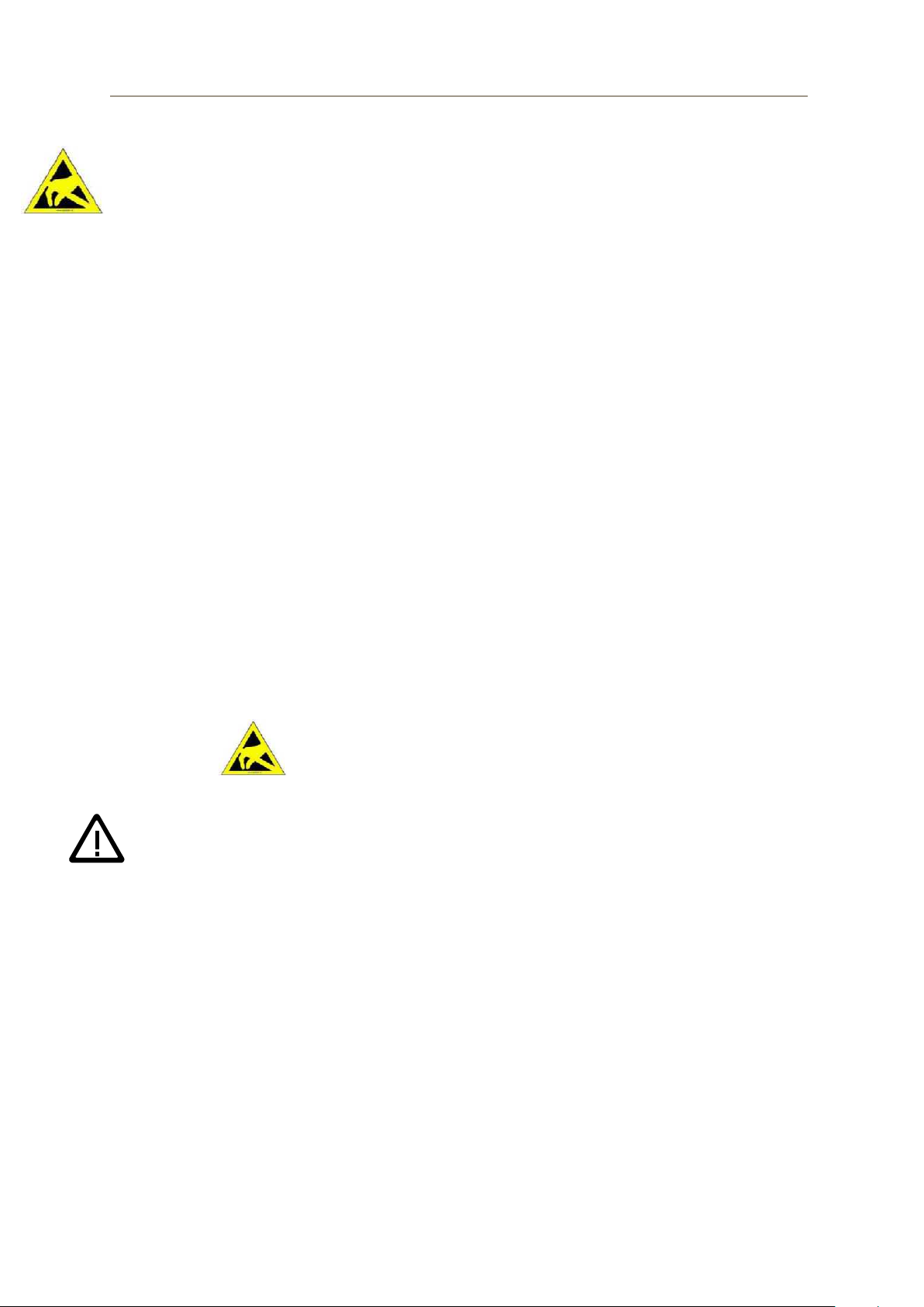
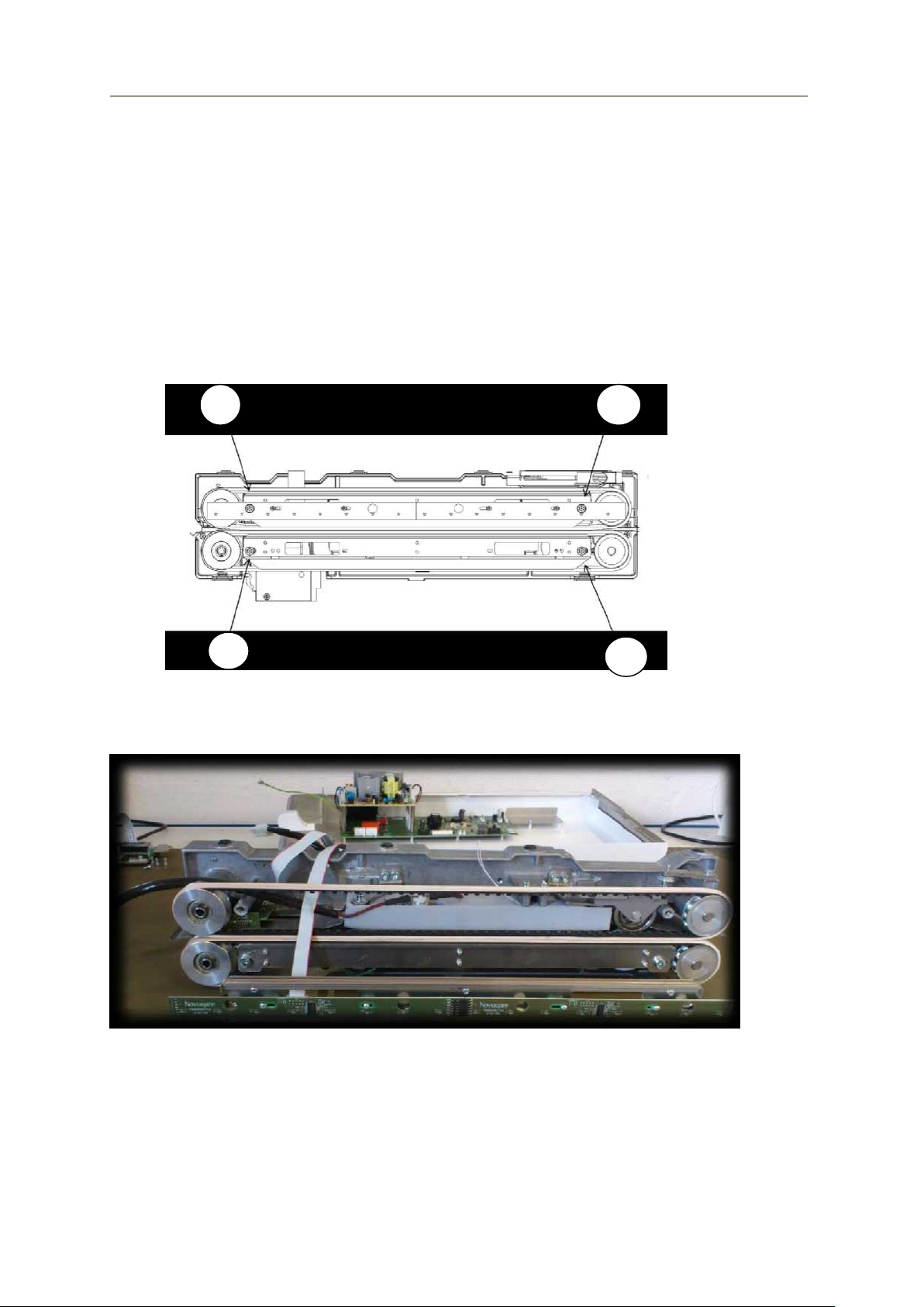
1.2.1 Risk of electric shock
Operating a running unit with open housing can result in an electric shock.
The areas marked in Pic 1 use mains voltage.
5
SERVICE MANUAL ProSeal Classic/Plus/Premium
Daily or after 400 seals
Yearly or after 100,000 seals
whichever occurs first
Visual seal seam check
Preventive maintenance
Check printed text on seal bag
Touching these areas can cause lethal injury!
Pic 1
1.2.2 Risk of burning
During operation, the heat elements can reach temperatures to 200°C.
Touching these parts or parts around them can result in severe burning.
1.2.3 Risk of Entrapment
In standby mode, the sealer transport belt can start to move to avoid radiant
heat on the transport belt.
1.2.4 Tools
Tools needed to service and repair the unit are:
Allen key
Circlip pliers
ESD protection
Knife
Non aggressive solvent and degreasing agent
Pinch pliers
3M VHB cleaner
, 4, 5 and 8
2 Preventive maintenance plan
In order to avoid damage or a failure of the unit as a result of insufficient
maintenance we recommend servicing the unit at least once every year or after
100,000 seals. During maintenance the above-mentioned precautions should be
followed. The sealing result should be checked after each maintenance.
6
SERVICE MANUAL ProSeal Classic/Plus/Premium
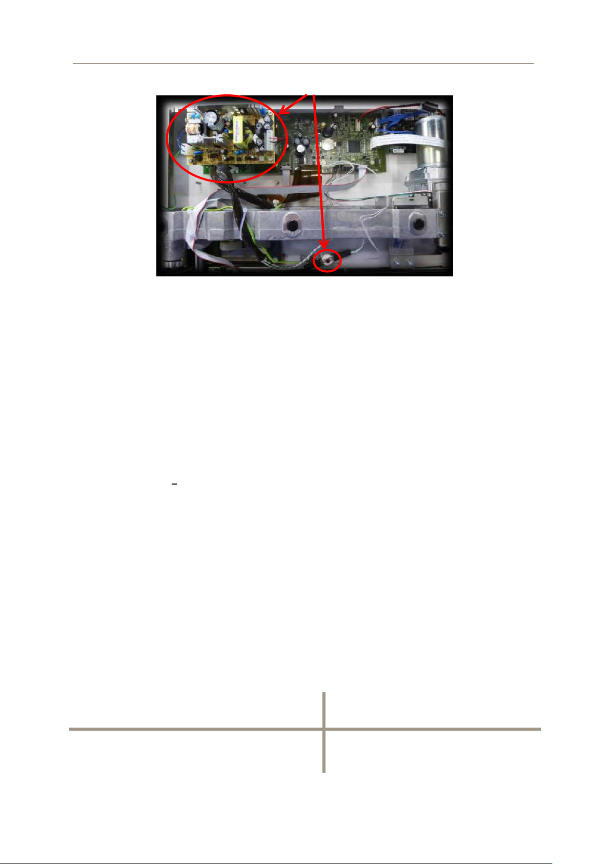
2.1 Opening the unit
Open the housing; remove the side covers (Pic 2)
Pic 2
Remove the screws on both sides of the top cover(Pic 3)
Pic 3
Lift the top cover somewhat on the front and pull it forward so you can remove
it (Pic 4 + Pic 5)
Pic 4
Pic 5
7
SERVICE MANUAL ProSeal Classic/Plus/Premium
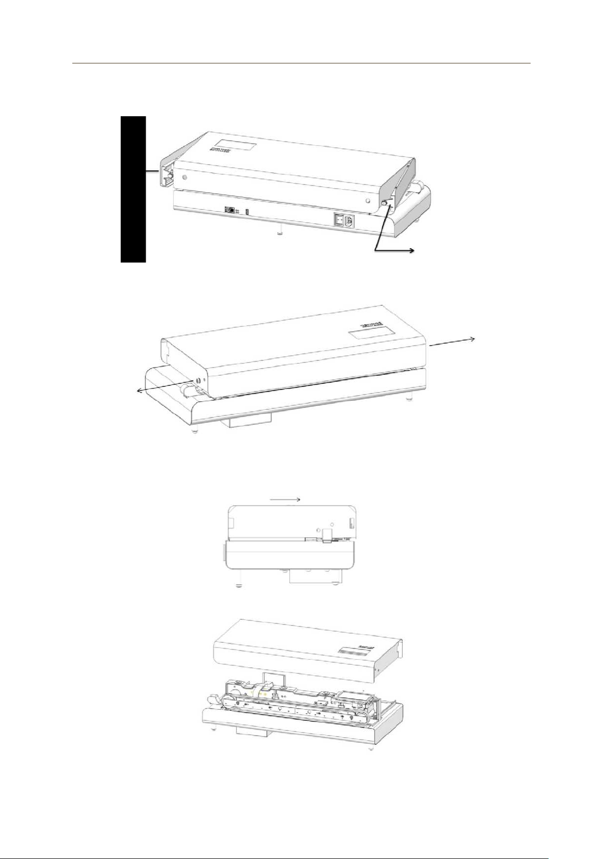
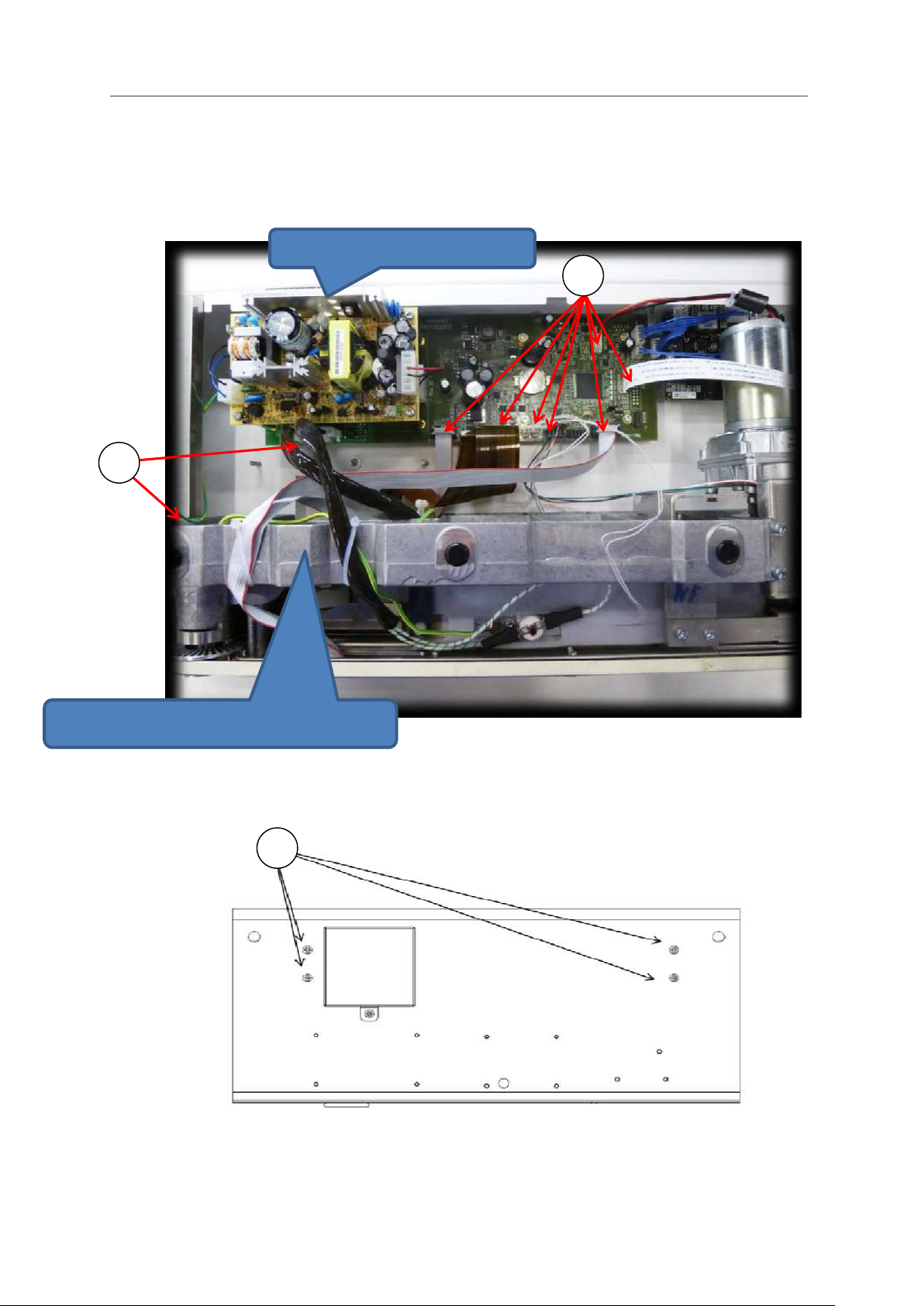
Control board
Base frame
2.2 Removing the base frame from the housing
Disconnect the wiring from the base frame and the control board (Pic 6). Use
special care with the flat cable coming of the display. This cable is easily
damaged.
Pic 6
Turn the unit on the front side, be careful with the touchscreen! Remove
screws (1) to separate the base frame from the housing (Pic 7). After
removing the screws, turn the sealer back.
Pic 7
8
SERVICE MANUAL ProSeal Classic/Plus/Premium
2
2
2
2.3 Replacing the PTFE material
The belt guides and the heating rails are lined with a non-stick strip (PTFE tape). It is
non-stick so your pouches will not stick on the heating rails. It is also on the belt
guides which expands the life of the transportation belts.
For preventive maintenance the PTFE material on the heating rails and belt guides
must be replaced.
2.3.1 The belt guides
The base frame has been removed from the housing.
Unscrew the belt guides (Pic 8)
Pic 8
Press the upper belt guide down. The top of the upper belt guide can now
move forward and the whole upper belt guide can be removed.(Pic 9)
Pic 9
When the upper belt guide is loose, the lower belt guide can be pulled out.
9
SERVICE MANUAL ProSeal Classic/Plus/Premium
Remove the press plate and the guide plate of the upper belt guide assembly
(Pic 10)
Pic 10
Remove the worn PTFE strips on the guide plate and press plates.
Clean off the bonding agent residues with a solvent and degrease the bonding
surface with a non-aggressive degreasing agent.
Stick the new PTFE tape on the guide plate and press plate; do not touch the
cleaned bonding surface and press the tape over the complete area
thoroughly.
Reinstall the belt guide assembly. Make sure that the press plate moves
freely.
See paragraph 4.3.2 for the mounting instruction of the belt guide assembly to
the base frame; for preventive maintenance, see paragraph 2.3.2.
2.3.2 The heating elements
Disconnect the ground wire of the upper and lower heating element with a
plier.
Attention! Do not pull the cables; this could damage the heating
elements! Use a plier on the connector.
Remove the upper pressure roller (Pic 11) by releasing the pressure with
screw (1).
After releasing the pressure remove the screws (2) to dismount the
suspension of the upper pressure roller.
Pic 11
10

SERVICE MANUAL ProSeal Classic/Plus/Premium
Unscrew the two screws on top of the heating elements to release the upper
heating element with isolation from the frame (Pic 12).
Pic 12
When the upper element is removed it is easy to remove the lower element
and insulation (Pic 13).
Pic 13
Remove the insulation foam from the heating rails (Pic 14).
Pic 14
Remove the worn PTFE strip. Clean off the bonding agent residues with a
solvent and degrease the bonding surface with a non-aggressive degreasing
agent. Stick the new PTFE strip on the element. Cut the PTFE strip to fold the
11

SERVICE MANUAL ProSeal Classic/Plus/Premium
1
strip around the heating cables. Do not touch the cleaned bonding surface and
press the strip thoroughly over the complete area.
Cut a notch into the PTFE strip (1) (Pic 15).
Pic 15
See paragraph 4.3.1 for the mounting instruction of the heating elements to
the base frame.
2.4 Transport belts
During use, the transport belts in the ProSeal will start to get worn out. It is therefore
important to replace the transport belt during preventive maintenance.
Remove the belt guides (paragraph 2.3.1). It is not necessary to remove the
heating elements.
Remove the clamp with a circlip plier holding the smooth wheel in place
(Pic 16). Do this with the upper and lower wheel.
Pic 16
Remove the upper and lower smooth wheel (Pic 17) and replace the transport
belt. Make sure that the arrows on the belt are pointing in the movement
direction of the belt.
Pic 17
12

SERVICE MANUAL ProSeal Classic/Plus/Premium
2
1
1
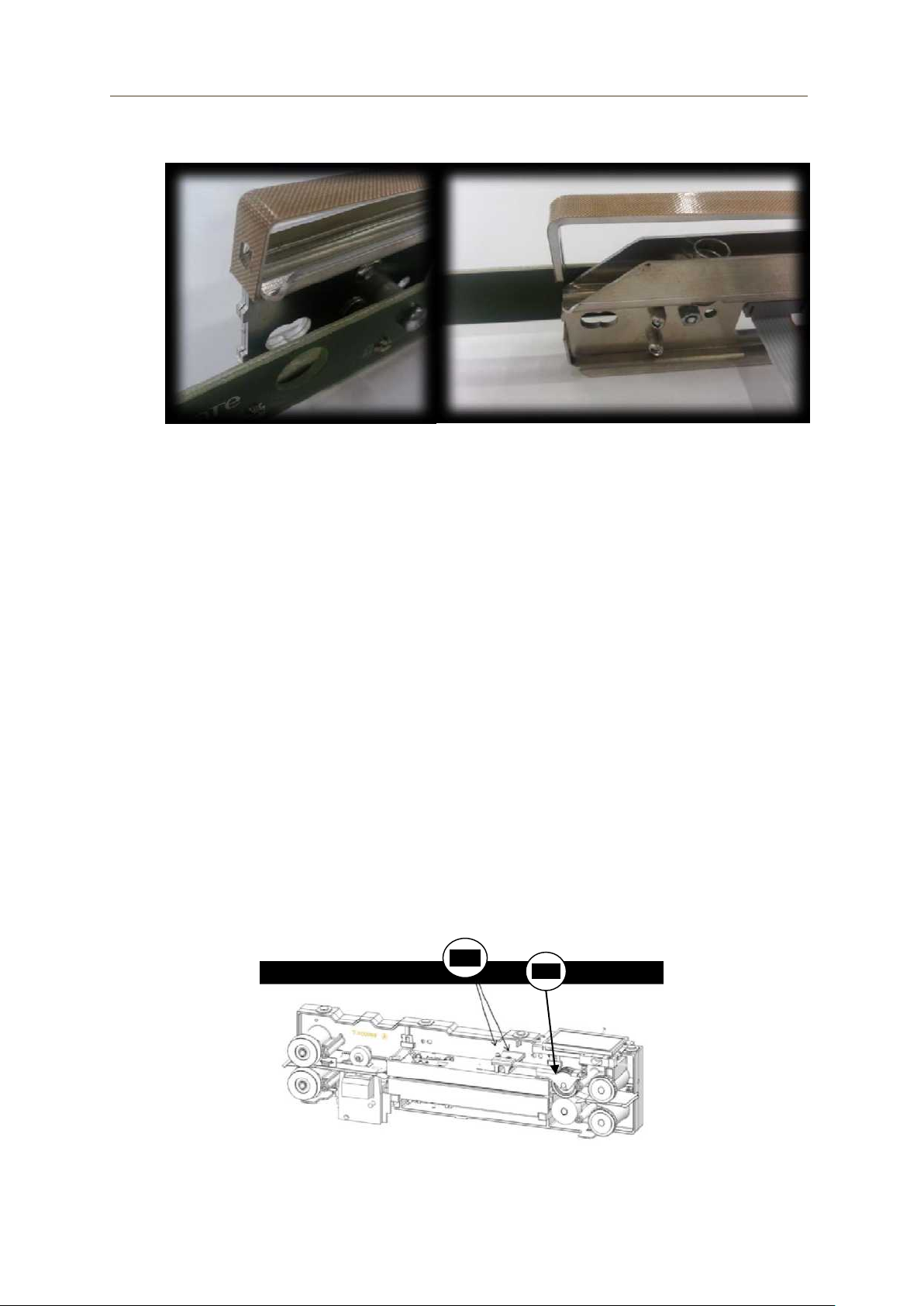
Tension the belt by hand and fasten the belt pulley. (Pic 18)Make sure that the
belt is not sag down.
Pic 18
2.5 Printer (only ProSeal Premium)
We recommend to exchange the printer ribbon each time during maintenance.
Remove screw (1) and remove lid (2). (Pic 19).
Pic 19
Unscrew the fastening screws a couple mm to release the printer module. (Pic
20)
Pic 20
Remove the printer ribbon from the printer module. Pull at the printer ribbon at
the bottom side of the printer module to remove it.(Pic 21)
Pic 21
13

SERVICE MANUAL ProSeal Classic/Plus/Premium
Turn the printer module upside down and clean the area around the printer
needles(Pic 22).
Pic 22
Switch the unit on.
Produce some seal samples with printing.
Check if the text on the seal samples is printed well.
If the text is illegible, turn the pin on the printer ribbon housing (2) (Pic 23).
Produce some seal samples again with printed parameters or text.
Check if the text on the seal samples is printed well.
If the text is illegible, check if the distance between the printer head and the
printer wheel is still 0.3-0.4 mm (depending on sealing material). Use a feeler
gauge with 0.3-0.4 mm thickness.
If the distance is not 0.3-0.4 mm, loosen the screw; see Pic 23 (1).
Pic 23
Lay a feeler gauge with a 0,3-0,4 mm thickness above the printer head.
Place the nylon printing wheel so that it is lying on top of the feeler gauge.
Fasten the screw and remove the feeler gauge.
Check the printing result.
2.6 Upper pressing wheel.
Check – at every maintenance inspection – if the surface of the upper pressing wheel
is worn out or damaged. If the upper pressing wheel is worn out or damaged, it
should be replaced.
14

SERVICE MANUAL ProSeal Classic/Plus/Premium
Nr.
Error text
Description
Possible problem / solution
1
Bag too small for
printer text
Selected printer text
doesn't fit on the
inserted pouch
Insert larger pouch or adjust printed text length
(chapter 7.9) or decrease dot spacing (printer
menu)
PCB on the inlet of the pouch mounted
incorrectly
Check “sensors active” parameter by inserting
pouch
Cable start sensors disconnected / broken
Start sensor PCB defect
Control PCB defect
The upper pressure wheel can be removed and exchanged.
See paragraph 4.3.4 for the mounting instruction of the upper pressure roller.
2.7 Lower pressing wheel
For the lower pressing wheel one should follow the same procedure as for the upper
pressing wheel. Check if the surface of the lower pressing wheel is worn out or
damaged. If the lower pressing wheel is worn out or damaged, replace the complete
part.
Remove the spur gear (1) from the shaft (Pic 24) by removing the clamping
pin Ø3x12mm (2).
Pic 24
The lower pressing wheel can be pulled out of the base frame and exchanged
with the new one.
Reassemble the unit in the opposite order; after assembly check if the
mechanism is running properly.
3 Trouble shooting
3.1 Error codes
Error codes higher than 12 are critical errors. Sealing is not possible anymore, only
after turning off and on the sealer, the error is reset. Always try first to turn the sealer
off and on to fix the problem. Also check if newer software version is available.
15

SERVICE MANUAL ProSeal Classic/Plus/Premium
2
Could not print due
to pouch depth
Not able to print due
to pouch insertion
depth
Pouch not entered deep enough into the sealer.
The pouch doesn’t run over the printer head
PCB on the inlet of the pouch mounted
incorrectly
Check “sensors active” parameter by inserting
pouch
Cable start sensors disconnected / broken
Start sensor PCB defect
Control PCB defect
3
Temperature too
low
Temperature below
set point - alarm limit
Pouch detected before temperature was
reached
Alarm limit temperature too low
Cable temperature sensor disconnected /
broken
Temperature sensor on heating element defect
Control PCB defect
4
Temperature too
high
Temperature above
set point + alarm
limit
Pouch detected before temperature was
reached
Alarm limit temperature too low
Cable temperature sensor disconnected /
broken
Temperature sensor on heating element defect
Control PCB defect
5
Pressure too low
Pressure below set
point - alarm limit
Set point pressure not correct
Alarm limit pressure too low
Pressure not correct (adjust the screw on the
pressure sensor according to paragraph 4.3.3)
Pressure wheel not clean
Pressure sensor defect
Control PCB defect
6
Pressure too high
Pressure above set
point + alarm limit
Pouch too thick
Set point pressure not correct
Alarm limit pressure too low
Pressure not correct (adjust the screw on the
pressure sensor according to paragraph 4.3.3)
Pressure wheel not clean
Pressure sensor defect
Control PCB defect
7
Speed too low
Speed below set
point - alarm limit
Pouch too heavy or thick
Alarm limit speed too low
Belt too loose or too tight
PCB on the inlet of the pouch mounted
incorrectly
Encoder sticker on the belt pulley damaged
Cable start sensors disconnected / broken
Start sensor PCB defect
Control PCB defect
16

SERVICE MANUAL ProSeal Classic/Plus/Premium
8
Speed too high
Speed above set
point + alarm limit
Pouch too heavy or thick
Alarm limit speed too low
Belt too loose or too tight
PCB on the inlet of the pouch mounted
incorrectly
Encoder sticker on the belt pulley damaged
Cable start sensors disconnected / broken
Start sensor PCB defect
Control PCB defect
9
Reverse error
Reverse button
pressed during
sealing
Reverse button pressed during sealing (only
used in log and reported to the NetCOM)
10
No seal command
received
Trying to seal when
the unit is in
NetCOM command
mode but no seal
command received
from the NetCOM
Send seal command from NetCOM and seal
again.
Use the sealer in “auto” mode instead of
“command” mode
11
NetCOM event
NetCOM sent an
error event that must
be acknowledged by
the user
Check manual NetCOM
12
NetCOM error
NetCOM
communication error
Cable(s) between control PCB and NetCOM
disconnected / broken
Wrong software version in NetCOM
No activated license for sealer in NetCOM
NetCOM defect
Control PCB defect
13
USB overcurrent
Overcurrent event
detected on (unit)
USB port
Short circuit in attached USB device
Control PCB defect
14
Printer over
temperature
Printer head over
temperature event
detected
Too much printer activity
Cable printer disconnected / broken
Printer head defect
Control PCB defect
15
Print buffer
underrun
Software error
Update firmware
16
Printer overcurrent
Ribbon motor or
needle drive circuit
detected an
overcurrent event
Too much printer activity
Printer head defect
Ribbon motor defect
Control PCB defect
17
Printer needle
stuck
Print current
measured while no
printer needle was
activated
Printer head defect
Control PCB defect
17

SERVICE MANUAL ProSeal Classic/Plus/Premium
18
Temperature
difference error
Large temperature
difference between
lower and upper
heater element
Cable heating element (power) disconnected /
broken
One of the 2 heating elements defect (check
resistance, should be almost equal)
Cable temperature sensor disconnected /
broken
Temperature sensor on heating element defect
Control PCB defect
19
Heating error
Heating elements
are on but the
temperature doesn't
rise (fast enough).
Cable heating element (power) disconnected /
broken
Thermostat upper heating element activated
Thermostat lower heating element activated
Heating element(s) defect (check resistance)
Cable temperature sensor disconnected /
broken
Temperature sensor on heating element defect
Control PCB defect
To reset thermostat:
Wait until heating elements are cooled down and
press button on thermostat to reset, use low force.
If thermostat was activated a click can be felt when
pressing the reset button
20
Temp1K8Calib
error
Temperature selftest of the control
PCB failed.
Control PCB defect
21
Temp1K2Calib
error
Temperature selftest of the control
PCB failed.
Control PCB defect
22
PressFullCalib
error
Pressure self-test of
the control PCB
failed.
Control PCB defect
23
PressNullCalib
error
Pressure self-test of
the control PCB
failed.
Control PCB defect
24
Pressure sensor 1
error
No communication
with pressure sensor
1
Cable pressure sensor disconnected / broken
Pressure sensor defect
Control PCB defect
25
Pressure sensor 2
error
No communication
with pressure sensor
2
Cable pressure sensor disconnected / broken
Pressure sensor defect
Control PCB defect
26
SPI flash error
Error while
communicating with
flash memory
Firmware update
Control PCB defect
27
Mains detection
error
Error while
measuring mains
frequency and
voltage
Mains voltage or frequency out of range for
sealer specification
Control PCB defect
28
Temperature
overheat error
Temperature of one
or two temperature
sensors above
210°C
Cable temperature sensor disconnected /
broken
Temperature sensor on heating element defect
Control PCB defect
18

SERVICE MANUAL ProSeal Classic/Plus/Premium
29
Software error
General software
error
Firmware update
Control PCB defect
30
Hardware error
General hardware
error
Firmware update
Control PCB defect
Measure the resistance between the
ground and the other contacts. If the
resistance on one of the contacts is
lower than stated, the printhead is
defective.
Attention!
A defective print head can destroy
the electronic system in the sealer.
3.2 Print head (ProSeal Premium)
Attention! A defective print head can destroy the electronic system in the
sealer.
Therefore, first check whether the print head is defective. Measure the resistance of
the individual contacts (Pic 25). If the resistance is not correct, the print head must be
replaced.
19
Pic 25

SERVICE MANUAL ProSeal Classic/Plus/Premium
1
4 Repair
4.1 Repair printer (ProSeal Premium)
The print head needs to be handled very carefully. For correct printing, the print head
needs to be replaced by following the next steps.
Attention! To avoid damage caused by electrostatic charging.
Before starting always remove the base frame from the housing
(paragraph 2.2).
Remove the printer ribbon housing (1) (Pic 26).
Pic 26
Remove the defective print head and replace it with a new one.
Place the blue lever (1) (Pic 27) on its middle position.
A space of 0.3-0.4 mm has to be applied between the print head and the nylon
printing wheel (see paragraph 2.5).
Loosen the screw (2) (Pic 16).
Lay a feeler gauge from 0.3-0.4 mm above the print head.
Place the nylon printing wheel so that it is lying on top of the feeler gauge.
Fasten the screw and remove the feeler gauge.
Place the printer ribbon housing back.
20

SERVICE MANUAL ProSeal Classic/Plus/Premium
Lift upper part connector
1 2 1
Put the blue lever (1) back on its lowest position (Pic 27).
Pic 27
Check whether the flat cable or the control board is defective. Before removing
the flat cable, the upper part of the connecter must be lifted (Pic 28).
Pic 28
4.2 Control board
Attention! Ground yourself to avoid damage caused by
electrostatic charging.
Disconnect all connectors from the control board (Pic 29) (1).
Remove the 2 connectors between the control board and the power supply,
and unscrew the power supply.
Disassemble the defective control board by loosening the socket head screws.
Dispose of the defective control board in an environment-friendly manner or
send it back to the manufacturer.
Install a new control board.
Re-assemble the complete unit in the opposite order. (Don’t forget to
reconnect the protective ground.)
21

SERVICE MANUAL ProSeal Classic/Plus/Premium
Pic 29
Check all functions. After replacing the control board, the speed, temperature and
pressure should be revalidated. For the ProSeal Classic the speed and temperature
should be validated. For instructions how to validate see section 5.
.
4.3 Assembling
Clean the parts and the lower housing of the unit with compressed air and
surface cleaner.
4.3.1 Heating elements
Turn the heat element upside down and place it in the isolation (Pic 30).
Pic 30
Place the heat element and isolation on the suspension of the base frame
(Pic 31).
22

SERVICE MANUAL ProSeal Classic/Plus/Premium
Pic 31
Align the upper heating element in line with the lower heating element, and
press the spring between the upper heating element and the clamp.(Pic 32)
Pic 32
Fasten the right side, of the upper heating element, until the heating elements
are just separated from each other(Pic 33)
Pic 33
Do the same with the left side, but the elements must barely touch each
other.(Pic 34)
Pic 34
23

SERVICE MANUAL ProSeal Classic/Plus/Premium
Upper belt wheel
Lower belt wheel
Connect the wiring of the upper and lower element. Do not forget to connect
the ground cable. Make sure that the correct cable is connected to the
corresponding control board slot.
4.3.2 Transport belts
Place the belt around the toothed wheel. (Pic 35), make sure that the arrows
on the belt are pointing in the movement direction of the belt.
Pic 35
Place the smooth wheel in the belt (Pic 37). Make sure the wheel with sticker
goes to the upper belt (Pic 36).
Pic 36
24
Pic 37

SERVICE MANUAL ProSeal Classic/Plus/Premium
Belt guide
Clamp wrong
Clamp good
Fix the smooth wheel with the original clamp and the circlip pliers. Make sure
the clamp is properly fixated. (Pic 38)
Pic 38
4.3.3 Belt guides
Mount the upper belt guide to the base frame, slide the guide over the inside
of the belt and press it down until the belt can move over the belt guide. Check
that the flat belt wheel and the toothed wheel run smoothly (Pic 39).
Pic 39
After fastening the upper belt guide, mount the lower belt guide in the same
way.
25

SERVICE MANUAL ProSeal Classic/Plus/Premium
4.3.4 Upper pressure roller
First mount the suspension and the pressure roller on the base frame (Pic 40).
Pic 40
Place the spring between the suspension and the load cell and fasten it with
the M4 screw (Pic 41).
Pic 41
4.3.5 Mounting the base frame in the bottom housing
Place the base frame upside down; be careful with the touchscreen! Place the
bottom housing over the base frame and secure it with 4 screws (Pic 42).
Pic 42
26

SERVICE MANUAL ProSeal Classic/Plus/Premium
Temperature
probe
Tachometer
Temperature
meter
Pressure
meter
•ProSeal
Pressure tool
Cable
ProSeal
Pressure
tool
Adapter
Pressure meter
After assembling the sealer, calibrate the replaced parts if possible. It is
advised to validate the pressure, speed and temperature to ensure the
ProSealer is still within specs.
5 Validation
During preventive maintenance, the ProSeal needs to be validated to ensure the
sealer is still within specifications.
5.1 Validation Kit
The ProSeal can be validated using the validation kit. This kit contains:
Tachometer
Temperature meter
Temperature probe
Heat conductive paste
Pressure meter
ProSeal Pressure tool
Adapter Pressure meter
Cable ProSeal Pressure tool
Pic 43
27

SERVICE MANUAL ProSeal Classic/Plus/Premium
Turn knob left.
Press button to select
Configuration.
Password blinking.
Turn knob to enter passcode.
To select press button. (all 4
digits need to be confirmed)
Turn knob right.
Turn knob right.
Press button.
Speed will blink.
Turn knob left or right to adjust
speed.
Confirm speed by pressing the
button.
Hold a pouch under the sensor
and validate the speed with the
tachometer.
Turn knob right .
Press button.
Put heat conducting paste on
the upper heat element.
Temperature will blink.
Validate the temperature with
the temperature meter and
probe.
Turn knob left or right to adjust
temperature.
Confirm temperature by
pressing the button.
5.2 Classic
5.2.1 Logging in
A service technician can use the service functions of the unit after logging in the
“service login”. The service password is 8729. Without this password, the
configuration settings can be viewed but cannot be changed.
5.2.2 Pressure
It is not possible to validate the pressure of the ProSeal Classic.
5.2.3 Speed
5.2.4 Temperature
5.3 Plus and Premium
The ProSeal Plus and ProSeal Premium can be validated using the validation menu.
In order to reach the validation menu, you must login as service.
28

SERVICE MANUAL ProSeal Classic/Plus/Premium
5.3.1 Logging in
A service technician can use the service functions of the unit after logging in the
“service login”. The service password is 8729. Without this password, the
configuration settings can be viewed but cannot be changed.
Press Menu Press Service login
Enter password 8729 Press Configuration
Press OK to log in
Press Service to enter service menu
After logging in, the validation menu can be reached to navigate to the service
menu. In this menu press validaton to reach the validation menu (Pic 44).
Pic 44
5.3.2 Pressure
Pic 45
In the pressure menu (Pic 45) the pressure set point and the measured pressure can
be seen. Both values should be equal(±1N). If there is a difference you can change
the measured pressure by adjusting screw (1) (Pic 46).
29

SERVICE MANUAL ProSeal Classic/Plus/Premium
Pic 46
For validation of the pressure you need the ProSeal pressure tool. Mount the
tool on the pressure load cell (Pic 47).
Pic 47
Adjust screw (1) so that the value of the measured pressure on the display of
the unit is “0”. The value of the display of the ProSeal calibration tool should
be equal to the pressure set point (±10N) (Pic 48). If the pressure exceed the
tolerance of 10N, a new load cell and load cell print needs to be installed.
.
Pic 48
Remove the ProSeal calibration tool, and check if the measured pressure of
the unit is equal to the pressure set point. If not, adjust it with screw (1)
(Pic 48).
You have validated the pressure of the unit.
5.3.3 Speed
Pic 49
Go back to the validation menu and press Speed.
In the speed settings (Pic 49) the speed settings can be changed.
By pressing on the + or – from Motor manual you can turn on or shut off the
motor manually.
30

SERVICE MANUAL ProSeal Classic/Plus/Premium
Press the + button to turn on the motor forward. On the right in the display you
can read the speed of the running motor; the value should be the same (± 10
mm/sec).
For validation adjust the speed to 120 mm/s (min. speed); check with a
tachometer if the speed of the belt is equal, check also at 170 mm/s
(max. speed).
The factory setting for speed is 160mm/s.
5.3.4 Temperature
Be aware of the tolerance of the temperature device you use.
Pic 50
Go back to the validation menu and press Temp.
In this Temperature menu (Pic 50) you see the temperature set point and the
measured temperature of the unit. There will always be a difference between
these values which is caused by the temperature control.
Place heat conduction paste on top of the heat element (Pic 51).
Pic 51
Change the set temperature to 100 °C
Place the temperature probe on top of the heat conducting paste.
Compare the temperature of the upper heat element with the temperature
meter. Be sure that the measured temperature is the same as the temperature
of the upper heat element (± 5°C).
Change the set temperature to 200 °C
Compare the temperature of the upper heat element with the temperature
meter. Be sure that the measured temperature is the same as the temperature
of the upper heat element (± 5°C).
6 Spare parts
Spare parts can be ordered by means of the enclosed drawings. Always state the
type designation and the serial number of the unit when ordering spare parts. Copy
the respective drawing and mark the required spare part.
31

SERVICE MANUAL ProSeal Classic/Plus/Premium
Part number
Description
Classic
Plus
Premium
66007025
PM kit
x
66007026
PM kit x x
The following spare parts are delivered as pre-assembled assemblies:
32
 Loading...