

SERVICE MANUAL
VS 60/90/130

TABLE OF CONTENTS
INTRODUCTION
CONTROL PANEL
PERIODIC MAINTENANCE
START TROUBLE SHOOTING
COMPONENT CHECK
ADVANCED TROUBLE SHO OTING
COMPONENT PLACEMENT
MENU NAVIGATION
WIRING DIAGRAM
INSTALLATION
TECHNICAL DATA
FEEDBACK
SPARE PARTS LIST
Rev D TABLE OF CONTENTS
INTRODUCTION
WARNING!
• As the sterilizer works with
steam under pressure, some
parts of it may become warm.
You should therefore exercise
the greatest caution whenever
working on the sterilizer.
• Hot steam may flow out of the
sterilizer when the door is opened.
• When handling materials and
loading the sterilizer, bear in
mind that the chamber and the
area close to the chamber entrance is very warm.
• Liquids must be sterilised in
special programs intended for
liquids. The sterilizer's liquid
program is solely intended for
the sterilisation of liquids in
open vessels.
General
The VS-series consists of vertical sterilizers with preprogrammed sterilisation programs. The sterilizer
works with steam produced in a chamber, fed with water from an external connection.
WARNING TEXTS IN THI S MANUAL
There are 4 di fferent admonitory levels in the manual:
• WARNING!
Factor, circumstance or state that can give rise to
the risk of personal injury.
• CAUTION!
Factor, circumstance or state that can give rise to
the risk of damage to machinery or the process.
• IMPORTANT!
Clarification that facilitates the understanding of
that described in this manual.
• TIP!
Factor, circumstance or state that can facilitate
execution or the process.
The following warning symbols is placed on the outside of the sterilizer (symbol acc. to ISO 3864)
If national requirements do not accept this symbol, the
symbol must be replaced by a suitable symbol valid in
the country were the sterilizer is used.
The warning symbol indicates that the person, responsible for the sterilizer must be fully conversant
with all requirements mentioned in the documents for
the sterilizer.
INTRODUCTION

Warranty
IMPORTANT!
The warranty on the delivered
product is invalidated by faulty
installation or an overlooked/
incorrect service interval/maintenance It must be possible to verify
service/maintenance.
A 2 year warranty is provided. However, not on those
components considered to be consumables, for example, door gaskets. For service work, reference
should be made to agreements with the supplier.
The Product Liability Act only applies when the instructions in this manual have been followed in their
entirety.
Copyright
Copyright © 2005 Getinge Skärhamn AB. All rights reserved.
All technical documentation provided by Getinge
Skärhamn AB is copyright protected and the property
of Getinge Skärhamn AB.
This publication may be downloaded from Getinge
Skärhamn's official website:
www.skarhamn.getinge.com.
The technical documentation is supplied as is. The
documentation can contain printing errors, technical
errors or other errors. Getinge Skärhamn AB reserves
the right to make alterations without prior notice.
No part of this publication may be copied without the
expressed permission of Getinge Skärhamn AB.
Manufacturer
Getinge Skärhamn AB Industrivägen 5
SE-47131 Skärhamn Sweden
Disposal
This product consists of (percentage by weight)
76 % Stainless steel
4 % Plastic
9 % Aluminium
5 % Brass
2 % Copper
4 % Electronics
When disposing of the sterilizer, it must be sorted at
source in accordance with the requirements set out in
the WEEE directive (2002(96/EC).
Contact your dealer when disposing of the sterilizer.
INTRODUCTION
CONTROL PANEL
2 3 4 5 6 7 8 9 10 11
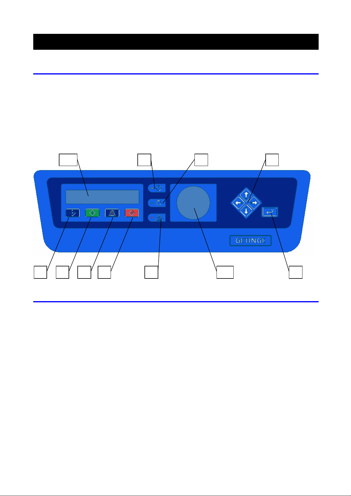
Layout of the control panel
1. PROGRAM SELECTOR button –
selection of the program
2. START button – start of the program
3. RESET button – reset a fault
4. STOP button – emergency stop
5. Yellow status lamp – program in progress
6. Green status lamp – program finished
7. Red status lamp – alarm
8. ENTER button – select items from the menu
9. Arrow keys – navigate through menus/lists
10. Pressure gauge – shows the chamber pressure
11. Display unit
1
Display unit
Shows the current status, program progres s, number of minutes after program start, number of completed
cycles and error codes.
IN STANDBY MODE SHOW S:
• Process name (program)
• Sterile time/temperature
Menu
Press the DOWN arrow to CYCLE COUNTER (twice)
and then press the ENTER button now press the
DOWN arrow to read the pressure and load sensor temperature (when the sterilizer features a
liquid program).
SHOWN DURING THE PRO CESS:
• Process name
• Process time
Home position:
Press the LEFT arrow for at least 4 seconds
To specifically read the load sensor temperature
(when the sterilizer features a liquid program),
press the ENTER button at the process name.
Operation, check
as not been locked before the start button has been pressed. Read
INCORRECT OPERATION, CHECKLIST
The table below lists the most common operating
faults that result in an alarm (error code) or that certain symptoms are experienced.
Check that usage was correct.
ALARM (ERROR CODE) REASON
Close door Door h
the text below the table, Correct operation, checklist .
Sterile error The sterilizer may have been overloaded. Read the Technical data se c-
tion.
Door open The handle has been activated befo re the finished signal has been dis-
played. Read the text below the table, Correct operation, checklist .
Process stopped The stop button has been pressed by the operator.
Heating error Can be due to items caught in the door.
No water Perhaps the water supply tap has not been opened
SYMPTOM REASON
Process abnormally long Can be due to:
• no water on the incoming supply.
• sterilizer overloaded. Read the Technical data section.
• leakage.
WARNING!
Consider the risk of burns when
loading the sterilizer.
CAUTION!
Only sterilise items intended for
sterilisation with steam and that
can withstand at least 121 degrees.
Only use loading equipment especially designed for the VS series.
Each standard basket may be
loaded with max. 12 kg of goods.
To ensure optimal ergonomics use
a lifting device when processing
heavy loads.
CORRECT OPERATION, CHECKLIST
1 Placing items in the sterilising chamber. Only use
loading equipment especially designed for the
VS series. Carefully check that nothing is caught
between the door and chamber.
Place moisture -sensitive items and low-mass
items at the top of the chamber.
Place heavy items at the bottom of the sterilis-
ing chamber.
Place dish-shaped items dish side down.
Place empty containers (bottles, test tubes,
etc.) with their opening downwards.
2 Close the door and pull the handle clockwise to
lock.
3 Press the START button, the cycle starts and will
be completed automatically.
OPERATION, CHECK

Recommended accessories
Basket, part no. 566687401
Solid, stainless steel container
48325031
4 When the display shows FINISH, the green status
lamp comes on and when the pressure gauge
shows zero the process is completed.
5 The display never shows FINISH and the green
status lamp for process finished never comes on if
the process is interrupted.
6 As soon as the door is opened FINISH is no
longer shown on the display, this provides information that if FINISH is not shown on the display,
then the goods in the chamber may have been
loaded by “someone else”, but not sterilised.
7 If the red status lamp for an alarm is on after a
sterilising process, the goods should be considered as unsterilised and must then be sterilised
again.
When the door is opened FINISH is no longer dis-
played. The display now shows:
INSTRUMENT 1340C (last selected program)
00.05.00_1340C
WARNING!
Remember the goods are hot after
sterilising.
Never attempt to open the door
until the pressure gauge has returned completely to zero.
LIQUID STERILISATION
• A special liquid program and a load sensor in the
chamber are required to sterilise liquids. The liquid process is solely intended for liquid sterilisation in open receptacles.
• Bottles should be filled to max. 80 % of their vol-
ume.
• Place the load sensor in the largest container.
When there is no space in the liquid for the load
sensor, use a control receptacle where the load
sensor can be placed. The volume of the liquid in
the control receptacle should be as great or greater than the liquid intended for sterilisation. Boiling
point for the liquid in the control vessel must be
the same as for the liquid to be sterilised.
• Use a receptacle with the smallest possible vol-
ume for the fastest processing.
OPERATION, CHECK
IMPORTANT!
If the process must be cancelled
for one reason or another press
the STOP button; the red status
lamp will come on and an audio
signal with sound.
Now press the RESET button and
wait for the pressure gauge to
drop to zero.
When the red status lamp indicating an alarm has gone out, press
the RESET button.
Open the door.
IMPORTANT!
When a process is interrupted,
there is a risk of steam streaming
out of the chamber when the door
is opened.
INTERRUPTED PROCESS
If the sterilizer stops the process:
1 Press the RESET button; the audio signal stops.
2 Wait until the pressure indication shows zero.
3 When the red status lamp has gone out:
4 Press the RESET button; the alarm text is no
longer displayed
If a process in progress has to be interrupted:
1 Press the STOP button; the text PROCESS
STOPPED is shown on the display. The audio sig-
nal sounds and the red status light comes on.
2 Press the RESET button; the audio signal stops.
3 Wait until the pressure indication shows zero.
4 When the red status lamp has gone out, press the
RESET button; the alarm text is no longer displayed.
OPERATION, CHECK

PERIODIC MAINTENANCE
General
WARNING!
The outer casing may only be
removed by technicians with documented experience.
WARNING!
Bear in mind when cleaning that
the chamber and the area close to
the chamber entrance is very
warm.
TIP!
The following Service kits are
available:
• Disks for solenoid valves
• Grease for door gaskets
WARNING!
The electrical power supply must
always be disconnected with all
types of maintenance work.
The manufacturer recommends at full utilization of capacity that at least the following maintenance operations should be performed at the specified intervals
with by service technicians. Monthly and weekly maintenance is carried out by the operator as set out in the
user manual.
Annual maintenance
ANNUALLY OR AT LEAST EVERY 400 CYCLES
UNLESS OTHERWISE STATED.
• Replace the filter where appropriate (accessory).
Check that the filter is not wet.
• Replace the plunger and O-ring on MV-1,MV-2,
MV-6 and MV-8. Refer to the section Component
check, 3. Solenoid valves.
• Check the door and its flange. Lubricate the mov-
ing parts by the door gasket. Use a grease suitable for use in the food industry.
• Replace the door gasket. At least every 3rd year
or 1200 cycles. See the section Component
check, 20. Door, Door gasket.
• Measure the pressure using a calibrated absolute
test pressure gauge, use the intended flange
marked VT on the sterilizer. See the section
Component check, 12. Absolute pressure sensor.
• Inspect and rectify any leakage from pipe cou-
plings and instrument connections. See the section Advanced trouble shooting, Trouble
shooting leakage .
• Check and clean the water outlet in the chamber.
At least every 800 cycles.
• Check that the monthly and daily maintenance
have been carried out correctly.
PERIODIC MAINTENANCE

• Perform a functional check of the electrical com-
ponents. See the section Component check. At
least every 1200 cycles or every 3rd year.
• Reset the service alarm from the Service mes-
sages men u. (situated under SE-
TUP/SYSTEM/SERVICE in the menu tree)
SAFETY CHECKS
• Check that the door seals against the steam pres-
sure during the sterilising process. See the section Component check, 20. Door.
• Check that the sterilizer can not be started when
the door has not been closed. See the section
Component check, 20. Door.
• Check that the door's counter-hold spring works
and prevents crush injuries. See the section
Component check, 20. Door, check the door
spring
• Inform the customer about the significance of the
warning signs.
• Inform the customer of the risks involved with the
program for sterilising liquids, if installed. Particularly the information that it is only permitted to
sterilise liquids inopen vessels.
PERIODIC MAINTENANCE
Monthly maintenance
MONTHLY, OR AS REQUI RED
• Clean the bottom filter. See the section Component check, 1. Chamber.
• Clean the chamber. See the section Component
check, 1. Chamber.
• Clean the door gasket and lubricate with the gre-
ase recommended by Getinge.
Daily maintenance
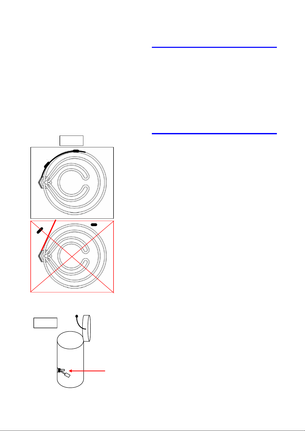
Fig. 1
• Check that the overheating protection sensor is fi t-
ted on the heating element, see fig 1. See the
section Component check, 6. Overheating pro-
tection.
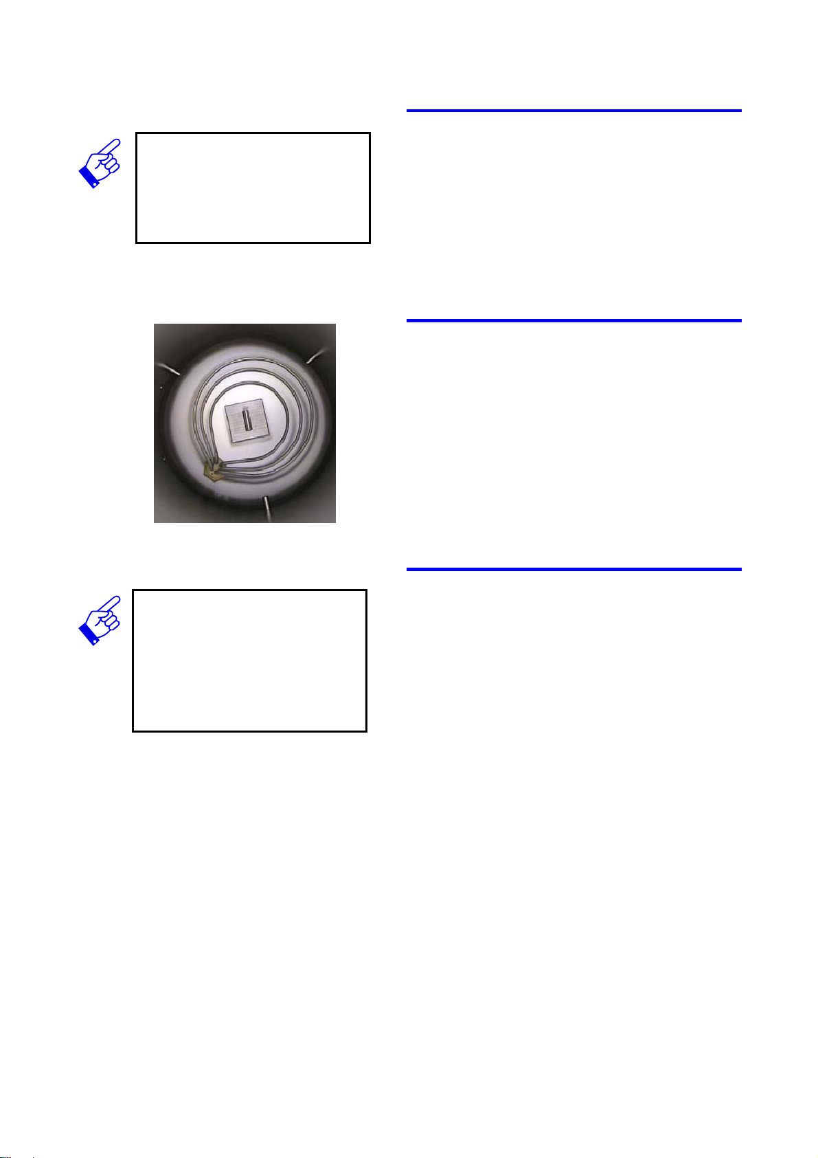
• Check that the level guard in the bottom of the
chamber is clean, fig. 2.
See the section Component check, 1. Chamber.
Fig. 2
PERIODIC MAINTENANCE

START TROUBLE SHOOTING
4 Final
3 Verify the
1 Start
Trouble shooting orientation
START TROUBLE SHOOTING HERE
Choose the error code/codes displayed and the symptom experienced in the table below. Carry out the pr e-
verification
Choose the
error code
symptom
scribed actions in the stated order, until the fault has
been identifie d and corrected.
CHECK PROCEDURE
1 START
Select the alarm (error code) or symptom in the
tables below.
2 Action
action
IMPORTANT!
The actions stated in the tables
are usually specific checks on the
components. However, the actions
can also represent advanced
trouble shooting and indicate the
specific component to be checked.
IMPORTANT!
After the action (for example,
component replacement) the action must be verified (e.g. manual activation).
In addition, it must be verified that
the error code/customer's experienced symptom has been corrected.
Several actions may be needed
with subsequent action verification, remember to always end
with verification against the
error code/symptom.
2 ACTION
Carry out the actions set out in the table. Carry
out the actions in the stated order, continue until
the fault has been corrected.
a. Check the components. In the event of a
component fault, repair or replace it. Instructions are enclosed with the spare part or are
set out after each check.
b. Should the check indicate that the component
is OK, return to the table in this section and
continue with next action as per point 2.
3 VERIFY ACTION
After repair/replacement the action must be verified. Instructions concerning verification are enclosed with the spare part or are set out after
each check.
4 FINAL VERIFICATION
(ERROR CODE/SYMPTOM VERIFICATION)
After ac tion verification it must be verified that the
displayed error code is not displayed again and
the experienced symptom no longer remains. This
is done by running a program and checking that
no error codes are displayed or the symptoms are
experienced.
START TROUBLE SHOOTING

Alarm (error codes visible on the display)
EXPLANATIONS
Explanations to references to sections stated in the
tables below:
CC : chapter Component check
Advanced chapter Advanced trouble
trouble shooting: shooting
Other references are given in plain text.
ERROR CODE EXPLANATION ACTIONS IN ORDER OF PRIORITY
GETINGE PACS 300
GETINGE PACS 300 DISPLAY
CLOSE THE DOOR Door unlocked at point of start 1. Operation, check
DOOR OPEN Door open during process 1. Operation, check
POWER FAILURE Power failure during process 1. Check external fuses.
PT-100 ERROR Error on load sensor during process 1. CC, 15. Load temperature sensor
SERVICE Service indicator. 1. Contact the service technician
Process does not start, frozen process
1. CC, 19. Software PACS cold start
2. CC, 18. Display
3. CC, 17. Circuit board
2. CC, 20. Door, (micro-switch)
3. CC, 17. Circuit board
2. CC, 20. Door, (micro-switch)
3. CC, 17. Circuit board
2. CC, 6. Overheating protection
3. CC, 17. Circuit board (Fuse)
4. CC, 17. Circuit board
2. CC, 17. Circuit board AI
STERILE ERROR Incorrect pressure/steam tempera-
ture in the sterile phase
PROCESS STOPPED The process has been stopped with
the STOP button
PRESSURE SENSOR
ERROR
UPDATE Battery replacement or circuit board
Pressure sensor incorrectly calibrated
fault
1. Operation, check
2. CC, 15. Load temperature sensor
3. CC, 12. Absolute pressure sensor,
4. CC, 17. Circuit board
1. Operation, check
2. CC, 18. Display
1. Advanced trouble shooting, Checks
with error code
1. CC, 17. Circuit board
START TROUBLE SHOOTING

ERROR CODE EXPLANATION ACTIONS IN ORDER OF PRIORITY
NO WATER Timeout level guard 1. Operation, check
2. CC, 10. Level guard
3. CC, 3. Solenoid valve MV-3
HEATING ERROR Timeout heater 1. CC, 6. Overheating protection
2. CC, 5. Relay
3. CC, 4. Heater
4. CC, 17. Circuit board
HEATING ERROR Leakage Trouble shoot according to the section
Trouble shooting leakage
MANUAL MODE Component manually ac tivated 1. Operation, check
2. An output on the circuit board has
been set to manual mode. ( menu
tree Diagnostic)
POST TREATMENT E RROR
POST TREATMENT E RROR
Outlet valve clogged CC, 3. Solenoid valve, MV-1
Screen in the chamber clogged CC, 3. Strainer
START TROUBLE SHOOTING

Symptom (experienced by user)
EXPLANATIONS
Explanations to references to sections stated in the
tables below:
CC: chapter Component check
Advanced chapter Advanced trouble
trouble shooting: shooting
Other references are given in plain text.
SYMPTOM ACTIONS IN ORDER OF PRIORITY
No ready signal 1. CC, 12. Absolute pressure sensor
2. CC, 3. Solenoid valve MV-2
3. CC, 11. Air filter
Instruments rust in the sterilizer 1. Poor quality instruments
2. Water cleaning filter – type de -ionization, check
(see documentation supplie d with the water filter)
Process time abnormally long 1. See the section installation. Electricity, Water
requirement
2. Advanced trouble shooting, Leakage test, check
3. Operation, check
4. CC, 22. Strainer
Humming noise in standby mode 1. CC, 3. Solenoid valves
Door hard to open/cannot be opened 1. CC, 3. Solenoid valve MV-8
2. CC, 20. Door, (lock)
Pressure gauge shows pressure with the door open 1. CC, 14. Pressure gauge
Steam leaks from the door 1. CC, 20. Door, door gasket
2. CC, 3. Solenoid valve MV-5
3. CC, 21 Pressure relief valve door gasket
Black background on the display 1. CC, 23 Fan.
2. CC, 18 Display
Unstable measurement value and text on display 1. CC, 23 Fan.
2. CC, 18 Display
3. CC 17 Circuit board
4. Check the power supply (Fluctuations?)
START TROUBLE SHOOTING

COMPONENT CHECK
TABLE OF CONTENTS
1. General ............................................................ 2
2. Chamber .......................................................... 2
3. Pipe/pipe couplings.......................................... 2
4. Solenoid valves................................................ 3
5. Heater............................................................... 5
6. Relay................................................................ 6
7. Overheating protection, resetting.....................6
8. Non return valve BV-1...................................... 7
9. Non return valve BV-2...................................... 7
10. Non return valve BV-3...................................... 7
10. Non return valve BV-3...................................... 7
11. Level guard ...................................................... 8
12. Air filter (accessory) ......................................... 8
13. Absolute pressure sensor ................................ 8
14. Ejector.............................................................. 9
15. Pressure gauge................................................9
16. Load temperature sensor (accessory)........... 10
17. Pressure relief valve....................................... 10
18. Circuit board...................................................11
19. Display............................................................ 12
20. PACS software...............................................12
21. Door................................................................ 14
22. Pressure relief valve, door gasket.................. 16
23. Screen............................................................ 16
24. Fan................................................................. 16
COMPONENT CHECK
page 1
1. General
IMPORTANT!
Only use Teflon tape that is intended for sealing pipe couplings
against steam pressure.
It is extremely important for safe functionality that all
nipples are tightened so that air, which can jeopardize
the sterilisation result, can not enter the chamber. If
pipe couplings must be removed while performing
checks, think about the following when assembling:
• Use ample Teflon tape, so that the tape partly
forms a seal and partly seals the threads.
2. Chamber
The chamber walls are cleaned using a mild lime dissolving agent. Rinse well. Drain by closing the door,
the bottom valve then opens automatically.
BOTTOM FILTER (ALSO SEE 23. SCREEN)
Lift out the filter. Clean
LEVEL GUARD (ALSO SEE 11. LEVEL GUARD)
Check that the rocker moves up and down easily.
TIP!
Check whether steam is let out
with an overpressure.
• Use soapy water on cold components
• Use a mirror on hot components
3. Pipe/pipe couplings
Check:
Start a 134 °C program. Trouble shoot when the sterilizer is in “Sterilisation” mode.
Check whether steam is let out.
Action:
Check according to respective component checks.
Also see 1. General.
Verification:
Check all pipes/pipe couplings again.
COMPONENT CHECK
page 2

IMPORTANT!
All valves open in an energised
state.
4. Solenoid valves
Pay attention to solenoid valves that hum! The noise
may be a forewarning about the coil starting to overheat due to it not working in a closed iron circuit. This
can occur when the moving core is influenced by the
magnetic forces from the winding and dirt prevents the
coil from reaching the end position. An air gap is then
formed in the magnetic circuit, which lowers the inductance in the coil resulting in increased current.
MV-1
Is fitted in the bottom of the sterilizer and has the task
of evacuating any remaining water in the sterilizer at
the end of the process.
Check:
Check that both the plunger and the area it runs in are
clean. Always change the O-ring that seals between
the coil and housing after removing the coil. Activate
MV-3 and fill the chamber. Activate MV-1 and MV4
(ejector). Check that the water runs out of the chamber again. Measure the voltage across the coil.
Action:
Clean and replace the plunger and O-ring. Replace
the entire valve if necessary.
Verification:
Check that the water level in the chamber is maintained for a long period (about 15 minutes).
MV-2
Is fitted at the rear, top edge of the sterilizer. Takes
care of pressure equalization after the post-vacuum
phase by releasing air into the chamber. The valve is
open when the sterilizer is in standby mode if the door
is locked. It becomes de-energised as soon as the
door is opened.
Check:
Check that both the plunger and the area it runs in are
clean. Always change the O-ring that seals between
the coil and housing after removing the coil. Activate
MV-4 and MV-2 on the diagnostic menu. The pressure
should not drop appreciably below atmospheric presssure. Measure the voltage across the coil.
Check for leakage: Dismantle BV-2. Activate MV-3
and the heater. No steam should come out of MV-2.
Action:
Clean and replace the plunger and O-ring. Replace
the entire valve if necessary.
Verification:
Run a sterilisation program. Check for leakage ac-
COMPONENT CHECK
page 3

cording to Check and that pressure equalization takes
place at the end of the program.
MV-3
Is fitted directly on the inlet. Loads the chamber with
water at the start of the process.
Check the opening function:
Activate MV-3 in the diagnostic menu; water should
then flow into the chamber.
Check the closing function:
In standby mode, check that the water level in the
chamber does not rise once the valve to the chamber
has been closed.
Action:
Clean and replace the plunger and O-ring. Replace
the entire valve if necessary.
Verification:
Run a sterilisation program. Check that no water enters the chamber after the process has ended and the
door is open.
IMPORTANT!
Minor steam leakage can be due
to a leaking gasket and has nothing to do with the MV-5 function
MV-4
Opens the water flow to the ejector to produce a vacuum
Check:
Check that water does not run out of the drain hose in
standby mode
Action:
Clean and replace the plunger and O-ring. Replace
the entire valve if necessary.
Verification:
Run a process and check again that water does not
run out of the drain hose in standby mode.
MV-5
Pressurises the door gasket before a program.
Check:
During the process, check that the door seals against
steam.
Action:
Clean and replace the plunger and O-ring. Replace
the entire valve if necessary.
Verification:
Check the door for steam leakage.
MV-6
Vents the chamber while the program is running.
Opens at the given time interval. Also simplifies eva-
COMPONENT CHECK
page 4

evacuation of the chamber pressure after sterilisation
is completed.
Check:
Build up a pressure in the chamber. Open MV-6. The
chamber pressure should drop. Check that the chamber pressure is maintained when MV-6 is closed. Pipes on the outlet side should be cooler than on the
pressurised side.
Action:
Clean and replace the plunger and O-ring. Replace
the entire valve if necessary.
Verification:
Run a program. Now verify according to Check, see
above.
MV-8
Evacuates the door gasket pressure after the completed process.
IMPORTANT!
A symptom of poor opening function in the valve is difficult door
opening.
TIP!
Ensure the heater is de-energised
before you measure the resistance.
Check:
Close and lock the door. Open MV-5 and open MV-8.
Water should flow out of the drain.
Action:
Clean and replace the plunger and O-ring. Replace
the entire valve if necessary.
Verification:
Run a process. The door should be easy to unlock after the completed process.
5. Heater
Is fitted in the bottom of the chamber and has the task
of heating the water dosed for the process.
Check:
Activate the heater. Measure with a clamp-on ammeter, this should show about 8 A/coil. The heater output
is 2000 W x3 coils, which gives a resistance of about
27 Ω/coil. Check the resistance.
Action:
Replace the heater with incorrect resistance.
If the clamp-on ammeter shows 0 A, and the relay and
circuit board are OK. Replace the heater.
Verification:
Verify by measuring the resistance.
COMPONENT CHECK
page 5
IMPORTANT!
Note that if overheating protection
trips due to a temperature outside
of the working range (0 - 300 °C),
the sterilizer must cool for a period so that the resetting button
shall remain pressed in. Wait until
the sterilizer is within the working
range again.
Note that it may also require a
great deal of force to press in the
overheating protection.
6. Relay
Is fitted in the distribution box. Its task is to connect
the heater to the power supply.
Check:
Activate the heater, measure the coil on the relay using a voltmeter. The coil is across A1-A2. Measure the
voltage on the outgoing connection 2 - 4 - 6
7. Overheating protection, resetting
Protects the heater against overheating, the protection
trips at approx. 300 °C. Requires manual resetting.
The sensor is positioned on the heater coil. The resetting button is positioned on the protection. A symptom
that the overheating protection has tripped is the timeout alarm, heating error.
Possible causes:
• That the sterilizer has been transported in tem-
peratures below freezing.
• That a fault has occurred in the temperature regu-
lation of the heater.
• That leakage results in the water being consumed
during the process.
The unit should always be de-energised when resetting.
CAUTION!
Check that the overheating protection sensor is fitted correctly on
the heater. Otherwise the sensor
has no function.
Check:
Check that the manual resetting button is pressed in.
Measure the voltage on the incoming and outgoing
pins on the protection. Voltage on the incoming but
not on the outgoing, means that the protection has
tripped or is faulty.
Action:
Replace the overheating protection. Make sure that
the sensor is correctly fitted on the heater. Also see
daily maintenance
Verification:
Check that the sterilizer display is lit.
COMPONENT CHECK
page 6

8. Non return valve
BV-1
Is fitted between MV-1 and the chamber and has the
purpose of preventing return flow through MV-3
Check:
Fill the chamber with an open door by opening MV-3.
Shut the main tap and let MV-3 remain energised and
open MV-4. Check whether water is running out from
the drain or that the level in the chamber drops over a
long period of time, at least 15 minutes.
Action:
Replace BV-1.
Verification:
As Check, see above.
9. Non return valve
BV-2
Is fitted between the air filter and MV-2. Its task is to
prevent steam, with a fault on MV-2 being forced through the filter.
Check:
Close and lock the door. Remove the air filter. Build
up a pressure; open MV5 and MV1, close MV1, activate the heater, open MV2. The pressure should rise
to 1 bar according to the front pressure gauge. Check
that no steam comes out of the air filter holder.
Action:
Replace BV-2. Check that the air filter is not wet.
Verification:
As Check, see above.
10. Non return valve
BV-3
Is fitted after MV-1 and has the task of preventing water from the ejector returning up into the chamber
Check:
Open MV-4 and MV-1. Check that no water enters the
chamber.
Action:
Replace BV-3
Verification:
As Check, see above.
COMPONENT CHECK
page 7

11. Level guard
Is fitted in the lower part of the chamber above the
heater. The task is to check the filling of the chamber.
Check:
Move the rocker arm up and down so the digital input
(Service, Diagnostic, Digital input) should switch between 1 and 0.
12. Air filter (accessory)
Its task is to supply the sterilizer with sterile filtered air
after the post vacuum phase.
Check:
The air filter must be dry. Check that pressure equalization takes place after the post vacuum phase in the
program.
Action:
Replace the filter.
Verification:
Run a program. Also see section BV-2, check.
CAUTION!
Connect the pressure gauge for
the absolute pressure to the outlet
on the lead-through at the rear of
the chamber.
TIP!
Start a program and stop it by
using the “Pause” switch in the
vacuum and sterile phase. Then
adjust the A-value (sterile phase)
and the B-value (vacuum)
TIP!
Use the program CS1000 (for PC),
for a basic calibration procedure.
13. Absolute pressure
sensor
Its task is to monitor and control the process.
Check:
Carried out with an independently, calibrated pressure
gauge for the absolute pressure, whose values are
compared with the values shown on the display. Area:
0 - 4 bar absolute pressure corresponds to 4 – 20 mA,
output signal with an open lid approx. 8 mA
Action:
When the deviation is significant, replace the sensor
and calibrate. With minor deviation, calibrate. Calibration is carried out via the menu tree. Step using the
UP arrow and the ENTER button through SETUP/
SYSTEM/ (password)/ CALIBRATION/ MANUAL CALIBRATION. Select the sensor and adjust index A or
B up or down depending on the type of fault indication. B with vacuum and A with a sterile pressure.
Verification:
Run a sterilisation program. Perform with an independently, calibrated pressure gauge for the absolute
pressure whose pressure values are compared with
the values shown on the display.
COMPONENT CHECK
page 8

14. Ejector
The ejector is mounted on the pipe from the water inlet to the drain. The ejector's function is to create an
underpressure in the chamber.
Check:
Activate MV-1 and MV-4 through the diagnostic menu.
The pressure shall, under the condition that BV-3 is
problem free and the water pressure is above 1.5 Bar,
reach a vacuum greater than 800 mBar within 15 minutes.
Action:
Clean the ejector. Any dirt or leakage in the ejector
connections cause impaired vacuum capacity.
Verification:
Check the depth of vacuum according to the check
section above.
15. Pressure gauge
CAUTION!
The pressure gauge only gives an
indication of the pressure and
should not be used during calibration.
Is placed on the front of the sterilizer. Shows the
chamber pressure even if the power is switched off.
Check:
When the door is open the pressure should show 0
±0.1 bar. Check that the pointer indicates a pressure
higher and lower than zero during a cycle.
Action:
Calibrate the pressure gauge according to the section
Pressure gauge adjustment. If it is not possible, replace the pressure gauge.
Verification:
Run a program. Compare the pressure gauge with the
pressure indication on the display.
PRESSURE GAUGE ADJUSTMENT
• Make sure the door is open.
• Open the front.
• Loosen the brass nipple at the rear of the pres-
sure gauge and lift out the pressure gauge.
• Pry loose the pressure gauge glass by inserting a
screwdriver in the notch at the top of the pressure
gauge glass.
• Insert narrow tipped pliers under the pointer and
lift it off.
• Adjust and press back the pointer in the right posi-
tion.
COMPONENT CHECK
page 9

16. Load temperature
sensor (accessory)
TEMPERATURE SENSOR
The sensor is placed in the lead-through to the chamber and is connected to contact piece X2 on the circuit
board. It monitors the sterile process and provides the
display with information about the temperature of the
liquid that sterilises and controls that the liquid is under 95°C before the door can be opened.
Check:
Loosen the connection on the circuit board and measure the resistance on the sensor with an ohmmeter.
The sensor's resistance should at 20 ° be about 120
ohm. The higher the temperature, the higher the resistance.
Action:
With a resistance above 150 ohm or 0 ohm. Replace
the sensor.
Check for leakage:
Check that there is no steam leakage from the sensor's lead-through – silicone seal.
WARNING!
Adjustments or actions that alter
the opening pressure on the
pressure relief valve may only be
performed by persons with documented experience.
Action:
With leakage – replace the silicone seal.
17. Pressure relief valve
The function of the pressure relief valve is to relieve
the pressure in the chamber, should this rise uncontrolledly.
Check:
Start a process. When “sterilisation” is reached, close
MV-1 and MV-6 as well as start the heater. Check using an independently calibrated pressure gauge for
absolute pressure that the opening pressure is 3.7
±0.14 bar (absolute pressure). Check that the pressure relief valve does not leak water or steam at normal sterilisation pressure – max 3.15 bar.
Action:
Clean the valve. Replace the valve if necessary.
Verification:
Run up the chamber pressure, activate the heater and
close MV1 and MV6. Read when the pressure relief
valve trips. Check that the valve does not leak during
a program
COMPONENT CHECK
page 10

CAUTION!
The display unit and the circuit
board unit must always be kept in
shielded bags until the components are to be installed in the
sterilizer. Make sure not to be
electro statically charged when
these parts are handled, by e.g.
touching an earthed heater or by
WARNING!
Lithium battery. Explosion risk.
Replace the battery with the same
type as recommended by Getinge.
TIP!
Battery
When battery replacement is necessary and no battery is available,
the sterilizer can temporarily be
run with jumper (see section 25
Software PACS, Cold start) in
cold start mode.
The calendar and process counter
do not work in cold start mode.
18. Circuit board
Is located in the casing to the right. Its function is to
bridge all input and output signals with the software
PACS. The circuit board houses, among others, the
flash memory that holds the PACS software and the
battery.
Check the circuit board:
• Incoming voltage on X23.
• That PT100/PT1000 jumpers are located cor-
rectly: PT 100 position
• Fuse 315 mA.
• Voltage on the battery, 3.6 V.
• Connect the cables and connectors.
Check the relays:
To check the function of a relay, activate each output,
connect a voltmeter between Line N (X23) and each
output. The voltmeter should show approx. 230 VAC.
On connection COM 1 ( X32) the board is equipped
with a serial communication port (RS232) for connection e.g. to a computer.
Action:
Replacing the battery.
Make a backup of the software according to the section 25 Software PACS, if possible.
Cut off the battery solder tags as close to the battery
as possible.
Do not solder on the circuit board!
Solder in the new battery on the old solder tags.
Check that the new battery's voltage is 3.7 V
Perform a cold start according to 25 Software PACS,
Cold start.
Action:
If the above does not correspond, correct or replace
the board.
Verification:
Run a prepacked program.
Replacing the circuit board
Move over the flashmemory circuit from the old board.
Check the circuit board according to the section
above.
Perform a cold start according to 25 Software PACS,
Cold start.
Set the time and date and the language version
Go to the menu TOOLS-PACS and select SAVE RAM
TO FLASH.
COMPONENT CHECK
page 11

19. Display
Is placed on the front of the sterilizer. Its task is to
show values and act as the interface to the PACS
software. The display board is connected to X26 on
the circuit board. The keypad in the decal is connected to contacts J1 and J3 on the display card.
Check:
Check the cables including connection X26. Check
jumper JP1. Should be fitted between pins 1 and 2.
Action:
Replace the display card.
Verification:
Run a program and make sure the display communicates without interference.
20. PACS software
Is installed in the flash memory on the circuit board.
Its function is to monitor and govern the entire sterilizer and the processes run on it. PACS also logs
events and alarms.
Action:
MAKE A BACKUP.
Follow the following when the sterilizer's program version is to be saved on a PC:
NOTE. The calibration settings will not be saved on
this back up.
X24
Connect your PC to contact X32 on the sterilizer use
the communications cable.
Start the CS 100 program. State the service password
Go to the menu TOOLS-PACS to RAM/
UPLOAD TO FILE.
Now save the backup file on the hard drive
in the PC.
LOAD A NEW BACKUP
Connect your PC to contact X32 on the sterilizer use
the communications cable.
Start the CS 100 program. State the password
Go to the menu TOOLS-PACS and select SAVE RAM
TO FLASH.
Go to the same menu and select RAM/ DOWNLOAD
FROM FILE.
Set the time and date and the language version
Go to the menu TOOLS-PACS and select SAVE RAM
TO FLASH.
COMPONENT CHECK
page 12

Verification:
connect an external pressure gauge intended for absolute pressure. Run a process and check the calibration against the display.
BACK UP THROUGH A NEW FLASH MEMORY
Connect your PC to contact X32 on the sterilizer use
the communications cable.
Start the CS 100 program. State the password
Go to the menu TOOLS-PACS and select SAVE RAM
TO FLASH
Switch off the power and change FLASH circuit
Make a “cold start” see below
Set the time and date and the language version
Go to the menu TOOLS-PACS and select SAVE RAM
TO FLASH
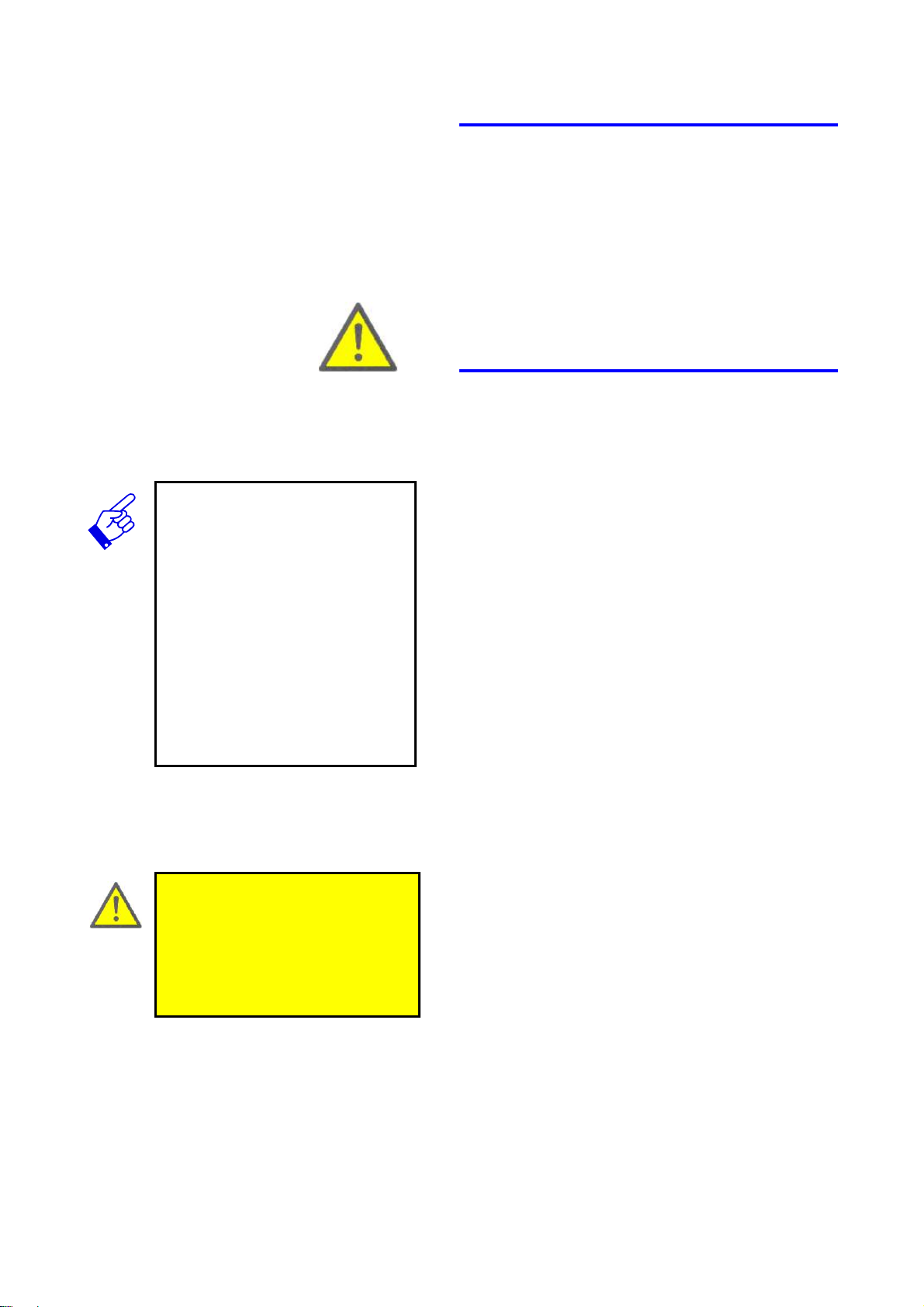
COLD START
Switch off the power and place the jumper (marked
with an arrow in picture) to position Cold start.
Switch on the power again, wait a few seconds.
Place the jumper in the Normal position
POST VACUUM ADJUSTMENT
How to navigate through the menus, see the section
Main menus. Password. Step as set out in the section Menu navigation. The post vacuum time is adjustable up to 30 minutes. A value lower than the factory setting can not be made.
COMPONENT CHECK
page 13

21. Door
Door is locked mechanically by a bayonet mount and
10 flanges. The door gasket seals through the gasket
groove being pressurised at the start of the process
which then presses against the door.
Open and close the sterilizer door several times in a
row and check that there is no play on the door and
hinge. Also check that the door spring has not become too weak or has broken.
Check:
Check that a process can not be started if the door is
not closed correctly. Check the hinge joints, microswitch and door lock.
Action:
• Clean and lubricate the door's moving parts.
• Check the wear to the hinge joint, change if nec-
essary.
IMPORTANT!
The door must be fully open (110°)
to carry out the action.
• Check the micro-switch by activating it manually
and read the display (switches between the program parameter and “
• Check the door lock moves easily and does not
jam. Check especially that it reaches all the way in
the deactivated position.
Verification:
Open and close the door. The door's movement
should not be more resistant than it can be closed using normal force. In general as in Action.
Check the door spring:
Check that the door spring has not become too weak
or has broken by opening the door. The door spring
shall prevent the door from shutting.
Action:
• Remove the door's plastic cover
• Open the door as far as possible
• Loosen the nut (6)
START OK” on the display)
7 6 8
• Loosen the index screw (7). Remove the door
• Remove both clasps holding the spring axle. Se-
cured with six nuts under the axle
• Remove the circlip (8) located at the end of the
spring axle.
• Pull off the axle
COMPONENT CHECK
page 14

• Change the spring. Press the spring leg in the
door holder.
• Refit in the reverse order
• Centre the door with the help of the screw (7)
Verification:
Open the door and check that the door spring prevents the door from shutting.
DOOR GASKET
Door is locked mechanically by a bayonet mount and
10 flanges. The door gasket seals through the gasket
groove being pressurised at the start of the process
which then presses against the door.
Check:
Check that the gasket is in one piece and that the
contact surfaces are clean and lubricated with a food
industry grease.
Action:
The door gasket should be replaced after max 1200
cycles/once every 3rd year. Close the water connection before replacing the door gasket.
Open the door
Remove the gasket using a blunt tool
Check that the gasket groove is clean
Clean the groove if necessary
Grease the new gasket
Press the new gasket in the groove fully
IMPORTANT!
Check that steam does not blow
out around the door when the
pressure is built up.
Verification:
Close the door and run a program 134 °C check for
leakage. Also see section Component check, 4. So-
lenoid valves, MV-5 and MV-8.
COMPONENT CHECK
page 15

22. Pressure relief val-
ve, door gasket
Used to release the water pressure in the door gasket
groove if the pressure exceeds 4.8 bar
Check:
Check that the pipe after the pressure relief valve is
not hot during “sterilisation”.
Action:
Replace the pressure relief valve
Verification:
Run a new process and check whether the pipe is hot
23. Screen
Is positioned in the bottom of the chamber to prevent
a stoppage in the outlet.
Check:
Remove the screen, by lifting it straight up from the
chamber
Action:
Clean the screen
Verification:
Make a visual inspection that the screen is clean.
24. Fan
The fan is positioned behind the casing and is connected to contact piece X16 on the circuit board. Its
task is to lower the temperature under the casing
when the process is run.
Check:
Loosen the casing and check that the fan rotates
when a process is run. Check that the fan is voltage
fed.
Action:
Replace the fan
COMPONENT CHECK
page 16

ADVANCED TROUBLE SHOOTING
Flow chart
This section concerns advanced trouble shooting. The
different sub -sections below follow on from the previous sectionSTART TROUBLE SHOOTING. This means that all trouble shooting starts there.
ADVANCED TROUBLE SHOOTING, PROCESS DESCRIPTION

Process description
Steam is generated in the sterilizer through an exter-
5.
6. 7.
8.
3.
nal water feed that may be preceded by a softening fi lter.
Condensation is led off to the drain.
1. The door gasket is pressurized by MV-5 opening
and releasing water into the gasket groove.
2. The sterilizer is filled with water until the level guard cuts in.
3. The heater heats the water and the pressure rises.
1. 2.
4.
9.
10.
4. The steam pressure is monitored by the pressure
sensor which, via a PID -regulator, controls the
heater.
5. The temperature of the steam is monitored by the
pressure sensor (through a theoretical calculation).
6. The solenoid valve MV-1 is used to empty the water from the chamber.
7. The steam pressure is released via MV1 and MV6
8. The water pressure powers an ejector, which creates an underpressure in order to lowe r the
chamber pressure below atmospheric pressure.
MV4 releases the water pressure on the ejector.
9. MV-2 is used to release the air in the chamber.
10. MV-8 releases the door gasket's water pressure.
The door can now be opened.
ADVANCED TROUBLE SHOOTING, PROCESS DESCRIPTION

13.
11. 12.
14.
15.
16.
17.
18.
LIQUID LOAD
11. The door gasket is pressurised.
12. The sterilizer is filled with water until the level guard cuts in.
13. The heater heats the water and the pressure rises.
14. The steam pressure is monitored by the pressure
sensor which, via a PID -regulator, controls the
heater.
15. The load sensor monitors the temperature of the
liquid to be sterilised. The load sensor temper ature determines when the sterilizer switches to
sterilisation.
16. The solenoid valve MV-1 is used to empty the water from the chamber.
17. The steam pressure is released via MV1 and MV6
through ramping to prevent decoction.
18. When the liquid reaches a temperature below
95°C (controlled by the load sensor) MV-8 releases the gasket pressure and the door can be
opened. The process is complete.
PRE-TREATMENT
The purpose of pre-treatment is to remove air from the
chamber and from the goods. Air prevents the requisite contact between the steam and micro -organisms
to be killed.
Pre-treatment consists of steam injection and evacuation pulses in different processes depending on the
program selected. In addition, the humidification essential to killing mainly takes place during the pretreatment stage.
Pre-treatment process:
• Blow through (1)
MV-1 opens, the chamber is filled with water and
the heater then heats the water. MV-6 opens during the preset time.
• Pressure increases (2)
MV-6 closes and the heater heats. The pressure
rises to a preset level. The sterilisation pressure
should be reached during the final increase in
pressure. Sterilisation begins when the sterilisation pressure is reached.
ADVANCED TROUBLE SHOOTING, PROCESS DESCRIPTION

STERILISATION
Sterilisation takes place by maintaining the saturated
steam's relation (boiling point at a specific pressure).
The sterilisation phase is in progress during a pre programmed number of minutes at the preselected
temperature/pressure.
Sterilisation process:
• MV-6 opens during the preset time intervals.
• The pressure is controlled by means of the heater,
which heats as required.
POST TREATMENT
The purpose of post treatment is to reduce the moisture content in the goods. During post treatment the
pressure drops to atmospheric pressure or lower –
depending on the selected program. Post treatment is
completed by air being drawn in until the chamber is
at atmospheric pressure.
Post treatment process:
• MV-1 opens and releases the remaining water.
• MV-4 opens and the ejector starts.
• MV-6 opens after an additional few of minutes.
• When the right vacuum is reached (800 mBar)
time metering starts.
• When the time elapses MV-1, MV-4 and MV-6
close. MV-2 opens and air is drawn in and the
pressure rises towards atmos pheric pressure.
MV-8 opens and the door gasket pressure is released. The process is finished.
ADVANCED TROUBLE SHOOTING, PROCESS DESCRIPTION

PROCESS DESCRIPTION - LIQUID LOAD
PRE-TREATMENT
The purpose of pre-treatment is to remove air from the
chamber and from the goods. Air prevents the requisite contact between the steam and micro-organisms
to be killed.
Pre-treatment consists of steam injection and evacuation pulses in different processes depending on the
program selected. In addition, the humidification essential to killing mainly takes place du ring the pretreatment stage.
Pre-treatment process:
• Blow through (1)
MV-1 opens, the chamber is filled with water and
the heater then heats the water. MV-6 opens during the preset time.
• Pressure increases
MV-6 closes and the heater heats. The pressure
rises to a preset level just above the sterilisation
pressure to accelerate the heating of the liquid.
When the load sensor temperature approaches
the sterilisation temperature, the steam pressure
drops to the sterilisation pressure. Sterilisation
starts.
ADVANCED TROUBLE SHOOTING, PROCESS DESCRIPTION

STERILISATION
Sterilisation takes place by maintaining the saturated
steam's relation (boiling point at a specific pressure).
The sterilisation phase is in progress during a pre programmed number of minutes at the preselected
temperature/pressure. The load sensor monitors the
temperature of the liquid.
Sterilisation process:
• MV-6 opens during the preset time intervals.
• The pressure is controlled by means of the heater,
which heats as required.
POST TREATMENT
The purpose of post treatment is to lower the temperature of the liquid below boiling point at atmospheric pressure.
Post treatment process:
• MV-4 opens and the ejector starts.
• MV-1 opens at the preset time intervals to ensure
a slow pressure decrease and prevent decoction
of the liquid. The remainin g process water is released in connection with ramping.
• When atmospheric pressure is reached and the
temperature of the liquid (controlled by the load
sensor) is below 95°C, MV-1 and MV-4 close.
MV-2 opens and the atmosphere in the chamber
and the atmosph ere is the room are kept at the
same level. MV-8 opens and the door gasket
pressure is released. The process is finished.
ADVANCED TROUBLE SHOOTING, PROCESS DESCRIPTION

Trouble shooting leakage
IMPORTANT!
Trouble shooting takes place:
• At overpressure
Follow the method prescribed in
Check component, 2. Pipe/pipe
couplings.
TIP!
Check whether steam is let out
with an overpressure.
• On cold components:
use soapy water
• On hot components
use a mirror
1 Check for door leakage as set out in the section
Check component, 20. Door.
2 Check for leakage from the pressure relief valve
as set out in the section Check component, 16.
Pressure relief valve.
3 Check for leakage from the solenoi d valves as set
out in the section Check component, 3. Sole-
noid valves.
4 Check for leakage from the pipe couplings as set
out in the section Check component 2.
Pipe/pipe couplings.
5 Check for leakage on the temperature sensor's
lead-throughs as set out in the section Check
component, 15. Load temperature sensor.
6 Check for leakage from the ejector as set out in
the section Check component, 13. Ejector.
Calibration instruction
1 Connect a calibrated test pressure gauge to the
connection labelled PT on the sterilizer.
2 Start a 134 °C program.
3 Let the program run to post treatment
4 When the vacuum has stabilized, calibrate the B
parameter for the pressure sensor.
5 Check that the external pressure gauge shows
the same pressure as on the sterilizer's display.
6 Allow the sterilizer to finish.
7 Start a new 134 °C program. Let the program run
to “sterilisation”. Calibrate the A parameter for the
load sensor. Check that the external pressure
gauge shows the same pressure as on the steri-
lizer's display.
8 The sterilizer will calculate the theoretical sterile
temperature, based on the calibrated pressure va-
lues.
9 Allow the program to finish. Check the vacuum
setting during the post vacuum phase.
ADVANCED TROUBLE SHOOTING, TROUBLE SHOOTING LEAKAGE

MENU NAVIGATION
Orientation
Navigation through the menus is done using the four
arrow keys UP arrow, DOWN arrow, LEFT arrow,
RIGHT arrow and the ENTER key.
Navigate to your choice using the UP arrow and
DOWN arrow . The selection is indicated on the display by a cursor below the value to be changed.
To return to the previous level, press the left arrow
when the menu position is not selectable.
Press the ENTER key to activate your menu selec-
tion.
When a menu selection has been activated, one of
two actions can be performed.
• When the selection is a new menu position, a fur-
ther selection can be made.
TIP!
You can return at anytime to the
main menu by pressing the left
key and holding it down for 4 seconds.
• When the value can be edited, use the arrow keys
as set out above.
The selection can either be shown on one or two
rows. When one row is shown, this means the row
can be selected and activated using the ENTER key.
When two rows are shown, the first row shows the selected name and the second row the value linked to
the selection.
MENU NAVIGATION

Edit values
Press the ENTER key to set the display in edit mode,
i.e. make the selected value editable. The cursor is
positioned to the far left below the first character when
the value is selectable.
EDIT PRESET VALUES
Use the UP arrow and DOWN arrow to change a value. Different values are shown each time the arrow
key is pressed.
Save the value by pressing the ENTER key.
EDITING NUMERICAL VALUES
TIP!
When adjusting the sterile or post
vacuum times, the value can not
be set below the preset value.
The value can consist of several characters. The character with the cursor below can be edited.
The highlighted character can be increased or decreased by using the UP arrow or DOWN arrow.
Use the RIGHT arrow or LEFT arrow to select the
next editable character to the right respective left.
When you have finished, save the values by pressing
the ENTER key.
MENU NAVIGATION

THE MENU TREE
Main menus
Main selection: Program name, Program version,
Phase, Cycle counter and Setup menu.
Password service 120416
Navigate to your choice using the UP arrow and
DOWN arrow. The selection is indicated on the dis-
play by a cursor below the value to be changed.
To return to the previous level, press the LEFT arrow
when the menu position is not selectable.
Press the ENTER key to activate your menu selec-
tion.
1. PROGRAM NAME
Program name: Selected program
Params 1 Params 2: Sterilisation time & temp (or
Heating up)
Select program: Sub-menu to selected program.
Important, the sterilizer has a PROGRAM SELEC-
TOR button for this on the front.
Change parameter: Possibility to change the sterile
time and post vacuum time. Password 558
2. PROGRAM VERSION
E.g.
050121
3. PHASE
E.g.
PRE-TREATMENT
4. CYCLE COUNTER
Possibility to read the sterilizer's counter, pressure
and temperatures. E.g.
0210
Setup menu
5. SETUP MENU
Print Last Cycle: Not used.
System: To access the System menu.
Password: State
System menu: See the section System menu.
About: Software version
MENU TREE, MAIN MENUS

System menu
Navigate to your choice using the UP arrow and
DOWN arrow . The selection is indicated on the
display by a cursor below the value to be changed.
To return to the previous level, press the LEFT arrow
when the menu position is not selectable.
Press the ENTER key to activate your menu
selection.
The sterilizer's menu for installation specific
settings and unique machine settings.
Main selection: Calendar, Calibration,
configuration, Dipswitch, Service and Flash
memory.
1. CALENDAR MENU
Time and date settings
2. CALIBRATION MENU
Only possible with manual calibration
See separate section Calibration menu
3. CONFIGURATION MENU
See separate section Configuration menu
4. DIPSWITCH MENU
Not used.
5. SERVICE MENU
See separate section Service menu
6. FLASH MEMORY MENU
Save adjustments and changes to the flash memory.
Should always be done once adjustments and
calibrations have been made.
MENU TREE, SYSTEM MENU, ETC

Calibration menu
Main selection: Manual calibration, Automatic calibration and Compensation table.
Navigate to your choice using the UP arrow and
DOWN arrow . The selection is indicated on the dis-
play by a cursor below the value to be changed.
To return to the previous level, press the LEFT arrow
when the menu position is not selectable.
Press the ENTER key to activate your menu selec-
tion.
1. MANUAL CALIBRATION
Always use MANUAL CALIBRATION. To calibrate,
see the section Advanced trouble shooting, Cali-
bration
00 Not used
01 Not used
02 Not used
03 Pressure : Step the cursor to each value to be
changed. Verify with Enter
04 Not used
05 Not used
06 Not used
07 Load sensor: Step the cursor to each value to be
changed. Verify with Enter
2. AUTOMATIC CALIBRATION
Not used
MENU TREE, CALIBRATION MENU

Configuration menu
Main selection: Calendar, Calibration, configuration, Dipswitch, Service and Flash memory.
Navigate to your choice using the UP arrow and
DOWN arrow . The selection is indicated on the dis-
play by a cursor below the value to be changed.
To return to the previous level, press the LEFT arrow
when the menu position is not selectable.
Press the ENTER key to activate your menu selec-
tion.
1. LANGUAGE DATE UNI T
Settings related to countries
Language setting: Display language
Date format
Pressure format: NOTE! Must not be changed! The
sterilizer is calibrated based on bar.
Temperature format: NOTE! Must not be changed!
The sterilizer is calibrated base don degrees Celsius.
2. PRINTER
Printing Mode: Not used.
Logging interval low: Logging interval for the total
process excluding the sterilisation phase.
Logging interval high: Logging interval for the sterili-
sation phase only.
3. ALARM CLOCK
Not used
4. PACS ADDRESS
Possibility to give the sterilizer an Id. When there is
more than on sterilizer with the printer in the same location. 1-99
5. COMMUNICATION
Settings for the Com-ports (3) RS232 or RS485
Set for communication with the service software.
Must not be changed!
MENU TREE, CONFIGURATION MENU

Service menu
Main selection: Error log, Service messages and
Diagnostics.
Navigate to your choice using the UP arrow and
DOWN arrow . The selection is indicated on the dis-
play by a cursor below the value to be changed.
To return to the previous level, pres s the LEFT arrow
when the menu position is not selectable.
Press the ENTER key to activate your menu selec-
tion.
1. ERROR LOG
20 most recent error codes
The type of error code, in which phase of the program
and when.
2. SERVICE MESSAGES
Resetting of the service alarm (alarm every 400 process)
3. DIAGNOSTICS
Manual test of components. Set the value under MAN
and control with S:1 or S:0
Analog input: Shows the water, pressure and temperature values
Analog output: Not used.
Digital input: Shows the door switch and an external
level switch
Digital output: Check of all components
Test User Flag: Not used
Test System Flag: Not used
Test Printer: Not used
Test LED/buzzer: Functional check of the sterilizer's
audio signal and LEDs.
MENU TREE, SERVICE MENU

Component placement,
internal
1 Circuit board
2
3 Ejector
4 Solenoid valve MV-3
5 Non return valve BV-1
6 Solenoid valve MV-4
7 Solenoid valve MV-5
8 Solenoid valve MV-6
9 Solenoid valve MV-8
10 Heater
11 Relay
12 Overheating protection, ÖV300
13 Chamber
14 Level guard
15 Solenoid valve MV-1
16 Absolute pressure sensor
17 Pressure relief valve (Chamber)
18 VT/PT-outlet
19 Pressure relief valve (Door gasket)
20 Solenoid valve MV-2
21 BV-2
22 BV-3
COMPONENT PLACEMENT, INTERNAL

23
24
COMPONENT PLACEMENT, INTERNAL

COMPONENT PLACEMENT
Component placement,
outside
1. Water supply
2. Water connection
3. Water outlet
4. Handle
5. Control panel
6. Reset button, overheating protection
7. Printer port RS232 (accessory)
8. Mains supply
9. Door lock
COMPONENT PLACEMENT, OUTSIDE

CIRCUIT BOARD DIAGRAM
X1 Absolute pressure sensor
X2 Temperature sensor
X3
X9
X10:A1 Switch (Door)
X10:A3 Level guard water
X16:2 L1 (Phase)
X16:3 Fan
X16:4 MV-1
X16:5 MV-2
X17:3 MV-5
X17:4 MV-4
X17:5 MV-3
X18:3 MV-6
X18:4 Relay (Heater)
X18:5 MV-8
X19:4 Recorder
X20
X21
X23
X23:1 L1 (Phase)
X23:2 Neutral
X24 PC communication
X25
X26 Display
X27
X32
CIRCUIT BOARD DIAGRAM

WIRING DIAGRAM
KRETSKORTSCHEMA

INSTALLATION
CAUTION!
Installation must be carried by
technicians with documented
experience.
WARNING!
Make sure that the area where the
sterilizer is to be located can
withstand a load of at least 250 kg.
INTERNAL TRANSPORT
The easiest method to move the sterilizer is using a
pallet truck or a barrow with a minimum lifting limit of
120 kg.
UNPACKING
Check that the packaging is intact.
Check that the supplied goods correspond with the
order.
Check that the sterilizer is free from defects.
Transport damage must be reported immediately to the
carrier.
Setup
PREPARATIONS
Setup ought to be carried out by technicians with
documented experience.
The sterilizer must be located indoors with a maximum
ambient temperature of 35 °C and a relative, no
condensing, humidity of maximum 95 %.
CAUTION!
Ambient temperature, max 35 °C.
Ambient humidity, max 95 %.
PLACEMENT
The sterilizer is a floor model and must stand free, it
must not be enclosed. It should be positioned so that
loading and unloading can be performed without risk. It
must be possible to open the door fully. See the
recommended distances in the picture
Follow local safety regulations.
Once the placement of the sterilizer has been
established, anchor the sterilizer to the floor by each of
the three feet. This prevents the sterilizer from tipping. A
13 mm hole has been drilled in each foot. Use a screw
and plug intended for the surface in question. Make sure
there is a slight backward incline, i.e. the side of the door
should be slightly lower than the front, about 2 - 3 mm.
This is accomplished by placing a washer under each of
the front feet.
INSTALLATION

VS 90/60 1550mm
VS130 1750mm
130mm
INSTALLATION

Electrical connection
IMPORTANT!
The electrical connection of the
unit must be carried out by trained
personnel
Prior to carrying out any connection work, ensure that
the characteristics stated on the nameplate correspon d
to the mains supply to which it is to be connected. In
case of uncertainty as to the unit supply voltage,
VOLTAGE FLUCTUATION:
The electrical components tolerate a supply voltage
fluctuation of between -10 and +10 %. For larger
fluctuations, it is necessary to use a voltage stabilisation
system placed between the circuit-breaker and the
processor unit transformer. In this case, contact the
sales office.
POWER-SURGE PROTECTION:
A power-surge protection device (over current
protection) must be placed on the sterilizer’s AC power
supply. This protection is the responsibility of the
customer.
CIRCUIT-BREAKER:
A device enabling the sterilizer to be electrically isolated
must be inserted on all the live conductors (including
neutral). This switch or circuit-breaker must be part of
the building’s electrical equipment, positioned near the
unit, and must be easily accessible and marked as the
power switch for the unit, while stating its function.
CAUTION!
The sterilizer must be declared to
your electricity supplier in case of
a 230 single phase connection.
If the unit is connected in polyphase. Its characteristics
are as follows:
• Breaking power 63 A breaking the 3 phases as well as
neutral
Earth terminal making it possible to connect the isolating
device to the earth conductor without braking it.
The on and off positions must be marked: I on and O off
• Box IP 54
TYPE- Power (kW) Voltage (V) Current (A)
VS 60 - 130 6.1KW 230V Single phase 30A
VS 60 - 130 6.1KW 230X3V 20A
VS 60 - 130 6.1KW 400X3V + N 16A
Connect the sterilizer to the earth and according to the
specification of the manual. The installation must be
protected in accordance with the regulations in force.
Failure to comply with this instruction may result in
electrocution of the user and damage to the unit.
CONNECTION POWER SUPPLY
Open the front box.
INSTALLATION

WARNING!
Never work with energized
equipment.
The sterilizer must be earthed.
400V 3 phases connection
5-wire cable (3 phase + Neutral + earth)
No jumper
230V 3 phases connection
4-wire for 230V (3 phase (3 phase + earth)
Jumper between L2-N
230V single phase connection
3 wire (1phase + Neutral + earth).
Jumper between L1-L2-L3
With appropriate section to 60227 and 60245.
Pass the power cable through the rear housing provided
for this purpose.
Connect the power cable earth connector to the terminal
marked with the earth symbol
Connect the other end of the cable to the circuit-
breaker/cut-off device located on the outside.
Change of voltage:
This adaptation requires certain parts to be changed;
use the “Jumper kit” furnished with the machine to
perform this change. For further information see the
electrical diagram, or get in touch with the selling
company.
Terminal connection:
Also see “Wiring diagram X1”
400 V 3 Phases Jumper between E-G-H
230 V 3 Phases Jumper between A-G, B-E, C-H
230 V Mono Phase Jumper between N-A-B-C
INSTALLATION

CAUTION!
The water supply must be fitted
with a shutoff tap, as the sterilizer
must not be left without
supervision with the water
pressurized.
WARNING!
Risk of hot water from the drain
hose, exercise the greatest
possible caution.
Water connection
The incoming water must have a pressure between 1.5
bar and 6 bar with a temperature of about 15 °C.
Water quality <4 dH
The sterilizer is connected to a ½" water connection with
a shutoff tap. The sterilizer must not be connected with
hoses less than 12 mm. The hoses supplied with the
sterilizer are fitted with Gaz ½" G connections. The
hoses (two) are labelled “Inlet” and “Drain”.
The drain should be connected to a 6" cesspool, with a
capacity of 10 litres/min that can withstand 100° C.
Condensation can occur.
The drain hose must end at least 3 cm above the water
surface in the well.
The drain hose must not go higher than to the lower
edge of the chamber.
Diverse
Should the sterilizer be transported in temperatures
below -5 °C, the overheating protection on the sterilizer
may need to be reset. The error code Heating error
when a process is started indicates a symptom for this.
Keep all instructions and description of operation close
to the sterilizer.
Make sure the operator has read the User manual.
All other documentation supplied with the sterilizer must
be looked after by the operator. The documentation shall
be kept with the sterilizer until its service life comes to an
end.
INSTALLATION

TECHNICAL DATA
Dimensions/weight
Width/Depth 570/700 mm
Height VS60/VS90/VS130 1030/1030/1230 mm
Load height VS60/VS90/VS130 940/940/1140 mm
Weight VS60/VS90/VS130 100/106/115 kg
Operating weight VS60/VS90/VS130 107/113/122 kg
Capacity
Chamber, diameter 444 mm
Chamber, depth VS60/VS90/VS130 384/590/858 mm
Chamber, volume VS60/VS90/VS130 60/90/130 L
Instrument load VS60/VS90/VS130 12/24/36 kg
Electrical specifications
Electrical connection according to rating plate
Control voltage according to rating plate
Total output 6 kW (3 x 2 kW)
Power consumption 5 A (3 x 400 V), 9 A (3 x 230 V)
Heat emission while operational, closed door about 615 W
Heat emission in standby, open door 0 W
Other data
Chamber, calculation pressure 3.0 bar
Chamber, provisions AFS 1999:4 (ÅKN 71), Isbest PED 97/23 EEC)
Chamber/door, material EN 1.4404, AISI 316L
Water quality Max 4dH
Water pressure 1.5 - 6 bar
Water and drainage connections ½”
Water consumption during steam phase 7 litres
Water consumption per process 75 - 100 litres
Sound level less than 53 dB
Not intended for the USA market
TECHNICAL DATA

Type designations, select
• ? VS60
• ? VS90
• ? VS130
Serial number:
_______________________________
Points of view, tips or criticism:
_______________________________
_______________________________
_______________________________
_______________________________
_______________________________
_______________________________
_______________________________
_______________________________
_______________________________
_______________________________
_______________________________
_______________________________
_______________________________
_______________________________
_______________________________
_______________________________
_______________________________
_______________________________
_______________________________
_______________________________
_______________________________
_______________________________
_______________________________
FEEDBACK
Getinge Skärhamn works continuously to improve its
products.
Would you like to help us by submitting your points of
view, tips or criticism? Copy this page and send or fax
it to us.
All suggestions that result in the improvement of our
product will be rewarded. Getinge Skärhamn reserves
the right to assess whether the suggestion is an improvement
Points of view were submitted by:
Name .................................................
Telephone: .................................................
Address: .................................................
.................................................
.................................................
E-mail: .................................................
Send to:
Getinge Skärhamn AB
Industrivägen 5
SE-47131 Skärhamn, Sweden
Fax:+46 (0)304 600 229
E-mail: info@seska.getinge.com
Thanks in advance.
FEEDBACK
 Loading...