


GE ZIF360NHCLH, ZIF360NHCRH, ZIFP360NHALH, ZIFP360NHBLH, ZIFP360NHBRH Installation Guide
...Installation
Instructions
36” Built-In All-Refrigerators
and All-Freezers
Design Guide
With Installation Instructions
31-49140-1
10-17 GEA monogram.com
Safety Information
BEFORE YOU BEGIN
Read these instructions completely and carefully.
• IMPORTANT– Save these instructions for local inspector’s use. Observe all governing codes and ordinances.
• Note to Installer – Be sure to leave these instructions with the Consumer.
• Note to Consumer – Keep these instructions with your Owner’s Manual for future reference.
If you received a damaged unit, you should immediately contact your dealer or builder.
Skill Level – Installation of this unit requires basic mechanical, carpentry and plumbing skills. Proper installation is the responsibility of the installer. Product failure due to improper installation is not covered under the Monogram Warranty. See the Owner’s Manual for warranty information.

 WARNING
 Electrical Shock Hazard.
Plug into a grounded 3-prong outlet. Do not remove the ground prong. Do not use an adapter.
Immediately discontinue use of a damaged supply cord. If the supply cord is damaged it must be replaced by a qualified service professional with an authorized service part from the manufacturer.
Do not use an extension cord with this appliance.
Failure to follow these instructions can result in death, fire, or electrical shock.
Follow the instructions in the section Grounding the unit.
This appliance must be installed with a means in the fixed house wiring or circuit breaker for disconnecting the appliance from the electrical supply after installation.

 WARNING

 Tip Over Hazard.
These appliances are top heavy, especially with any doors open, and must be secured to prevent tipping forward which could result in death or serious injury. Read and follow the entire installation instructions for securing the appliance with the anti-tip system.
WARNING |
Explosion Hazard. |
Keep flammable materials and vapors, such as gasoline, away from appliance. Failure to do so can result in fire, explosion, or death.
 WARNING To reduce the risk associated with choking, do not allow children under 3 years of age to have access to small parts during the installation of this product.

 CAUTION Lifting Hazard
This unit is very heavy. To reduce the risk of person injury during maneuvering and installing this appliance, 3 people are required for proper installation.

 CAUTION Keep fingers out of the “pinch point” areas; clearances between the doors and between the doors and cabinet are necessarily small. Be careful closing doors when children are in the area.
For Monogram local service in your area, call 1.800.444.1845 or visit monogram.com. For Monogram service in Canada, call 1.800.561.3344
For Monogram Parts and Accessories, call 1.800.444.1845 or visit monogram.com.
2
31-49140-1
Consignes de sécurité
AVANT DE COMMENCER
Veuillez lire toutes ces instructions attentivement. |
Niveau de compétence – L’installation de cet appareil |
|
• IMPORTANT –Conservez ces instructions à |
exige des compétences de base en mécanique, menuiserie |
|
et plomberie. La responsabilité d’une installation adéquate |
||
l’usage de l’inspecteur local. Observez tous les codes et |
relève de l’installateur. La garantie Monogram ne couvre |
|
décrets en vigueur. |
||
pas les défectuosités du produit causées par une installation |
||
• Note à l’installateur – Assurez-vous de laisser ces |
||
inadéquate. Consultez le manuel d’utilisation pour des |
||
instructions au consommateur. |
renseignements sur la garantie. |
|
• Note au consommateur - Conservez ces instructions |
|
|
avec votre manuel d’utilisation pour consultation ultérieure. |
|
|
Si vous avez reçu un appareil endommagé, veuillez |
|
|
communiquer immédiatement avec votre revendeur ou votre |
|
|
entrepreneur. |
|

 AVERTISSEMENT
 Risque d’électrocution.
Branchez l’appareil dans une prise à 3 broches mise à la terre. N’enlevez pas la broche de mise à la terre.
N’utilisez pas un adaptateur.
Cessez immédiatement l’utilisation d’un cordon électrique endommagé. Si le cordon électrique est endommagé, son remplacement doit être exécuté par un technicien en réparation qualifié au moyen d’un cordon de rechange autorisé par le fabricant.
N’utilisez pas un cordon de rallonge avec cet électroménager.
Le non-respect de ces instructions peut occasionner un décès, un incendie ou un choc électrique
Suivez les instructions de la section Mise à la terre de l’appareil.
Le circuit électrique auquel cet électroménager sera raccordé doit comporter un disjoncteur ou un autre dispositif permettant de couper l’alimentation électrique à l’appareil après l’installation.

 AVERTISSEMENT
 Risque de basculement.
Ces électroménagers sont lourds du haut, notamment lorsqu’une porte est ouverte, de sorte qu’ils doivent être fixés pour prévenir un basculement vers l’avant susceptible d’occasionner des blessures graves ou la mort. Lisez et observez la totalité des instructions d’installation pour connaître la façon de fixer l’électroménager sur le dispositif antibasculement.
AVERTISSEMENT |
Risque d’explosion. |
|
Gardez les matières et les vapeurs inflammables telles que l’essence à distance de l’électroménager. L’omission de prendre cette précaution peut entraîner un incendie, une explosion ou la mort.


 AVERTISSEMENT Pour réduire le risque d’étouffement pendant l’installation de ce produit, ne pas laisser les petites pièces à la portée des enfants âgés de moins de 3 ans.

 AVERTISSEMENT Risque lié à la manipulation d’un objet lourd
Cet appareil est très lourd. Afin de réduire le risque de blessure pendant la manipulation et l’installation de cet électroménager, la participation de 3 personnes est nécessaire à l’exécution d’une installation correcte.


 AVERTISSEMENT Gardez vos doigts éloignés des points de pincement. Les espaces entre les portes et ceux entre les portes et l’armoire sont particulièrement restreints. Soyez prudent lorsque vous fermez les portes en présence d’enfants.
Pour joindre le service Monogram de votre région, composez le 1.800.444.1845 ou visitez monogram.com. Pour le service Monogram au Canada, composez le 1.800.561.3344.
Pour le service des Pièces et accessoires Monogram, composez le 1.800.444.1845 ou visitez monogram.com.
3
31-49140-1

Contents
Safety
Instructions for Standard Installation
Planning Guide
The Installation Space Dimensions and Clearances Customization Basics Refrigerator Location
1/4” Framed Panel Dimensions 3/4” Overlay Panel Dimensions Side Panels
ZUG2 Grille Panel Dimensions 130° Door Swing
Installation Instructions
Tools, Hardware, Materials Grounding the Unit
Step 1. Remove Packaging
Step 2. Install Water Line
Step 3. Install Side Panels
Step 4. Anti-Tip Procedures Step 5. Level Unit
Step 6, Secure Unit to Wall Step 7. Adjust Door Swing Step 8. Install Grille Panel Step 9. Install Framed Panels Step 9A. Install Overlay Panels Step 10. Connect Water Supply Step 11. Start Icemaker
Step 12. Install Toekick
Instructions for Flush Installation
Planning Guide
The Installation Space Dimensions and Clearances Custom Handle Design Guide 1/2” Overlay Panel Dimensions 3/4” Decorative Panel Dimensions 3/4” Raised Door Panel Routing 3/4” Raised Grille Panel Routing 3/4” Raised Door Panel Routing
for Unified Installation Side Panels
Side Cleats
ZUG2 Grille Panel Dimensions
2 |
Unified Door Panel Dimensions |
30 |
|
5 |
Refrigerator Location |
30 |
|
6 |
Installation Instructions |
|
|
Tools, Hardware, Materials |
31 |
||
6 |
Grounding the Unit |
31 |
|
8 |
Step 1. Remove Packaging |
32 |
|
8 |
Step 2. Install Water Line |
32 |
|
9 |
Step 3. Install Side Panels |
32 |
|
9 |
Step 4. Install Case Trim |
33 |
|
10 |
Step 5. Anti-Tip Bracket |
33 |
|
10 |
Step 6. Level Unit |
35 |
|
11 |
Step 7. Adjust Door Swing |
36 |
|
|
Step 8. Install Grille Panel |
36 |
|
12 |
Step 9. Install overlay Panels |
37 |
|
12 |
Step 10. Connect Water Supply |
38 |
|
13 |
Step 11. Start Icemaker |
38 |
|
13 |
Step 12. Install Toekick |
38 |
|
14 |
Instructions for Stainless Steel Installation |
39 |
|
14 |
Planning Guide |
|
|
17 |
|
||
The Installation Space |
40 |
||
17 |
|||
Dimensions and Clearances |
40 |
||
18 |
|||
Customization Basics |
42 |
||
18 |
|||
Refrigerator Location |
42 |
||
19 |
|||
130° Door Swing |
43 |
||
20 |
|||
|
|
||
21 |
Installation Instructions |
|
|
21 |
Tools, Hardware, Materials |
44 |
|
21 |
Grounding the Unit |
44 |
|
22 |
Step 1. Remove Packaging |
45 |
|
Step 2. Install Water Line |
45 |
||
|
|||
23 |
Step 3. Install Side Panels |
45 |
|
Step 4. Anti-Tip Bracket |
46 |
||
23 |
|||
Step 5. Level Unit |
48 |
||
24 |
|||
Step 6, Secure Unit to Wall |
49 |
||
25 |
|||
Step 7. Adjust Door Swing |
49 |
||
26 |
|||
Step 8. Connect Water Supply |
50 |
||
27 |
|||
Step 9. Start Icemaker |
50 |
||
28 |
|||
Step 10. Install Toekick |
50 |
||
|
|||
29 |
|
|
|
30 |
|
|
|
30 |
|
|
|
30 |
|
|
4
31-49140-1

Instructions for Standard Installation
5
Design Guide - Standard Installation
THE INSTALLATION SPACE
Water And Electrical Locations
Electrical and water supply must be located as shown.
The Cutout Depth Must Be 24” (60.96 cm) Minimum
The unit will project forward, slightly beyond adjacent cabinetry, depending on your installation.
Cutout Depth Beneath a Soffit:
When installed beneath a soffit, the soffit cannot exceed the 24” (60.96 cm) installation depth shown. The top case trim overlaps the bottom of the soffit.
Additional Specifications
•A 115 volt 60Hz., 15 or 20 amp power supply is required. An individual properly grounded branch circuit or circuit breaker is recommended. Install a properly grounded 3-prong electrical receptacle recessed into the back wall. Electrical must be located on rear wall as shown.
•Water line can enter the opening through the floor or back wall. The water line should be 1/4” O.D. copper tubing or QuickConnect™ kit between the cold water line and water connection location, long enough to extend to the front of the unit. Installation of an easily accessible shut-off valve in the water line is required.
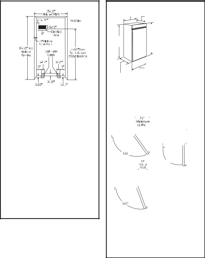
DIMENSIONS AND CLEARANCES
35" Case Width
*83-1/2" at Rear
Depth Including
Handles 26-7/8"
25-3/8" Case Depth
|
|
* Shipping height. The |
||
|
|
|||
|
|
|
product can be adjusted |
|
|
|
|
||
|
|
|
to fit into a cutout that |
|
|
|
|
is 84-1/2” (214.63 cm) |
|
|
*84" From |
|||
|
max. height. Note that |
|||
|
Floor to |
the top case trim at the |
||
|
Top Frame |
|||
|
|
|
front is 1/2” (1.27 cm) |
|
|
|
|
||
|
|
|
higher and will overlap |
|
|
|
|
upper cabinetry or soffit. |
|
|
|
|
Use leveling legs and |
|
|
|
|
||
|
|
|
wheels for a maximum |
|
|
|
|
1” (2.54 cm) height |
|
36" Frame to |
||||
adjustment. |
||||
Frame Width |
|
|||
Product Clearances
These units are equipped with a 3-position door stop. The factory set 115° door swing can be adjusted to 90° if clearance to adjacent cabinets or walls is restricted. Order WX14X99 door stop for precise settings between 90° and 130°.
|
|
130° Door Swing |
90° Door Swing |
||||||||||||||||||||
|
|
|
|
|
|
|
|
|
|
|
|
|
|
|
4” Minimum |
||||||||
|
|
|
|
|
|
|
|
|
|
|
|
|
|
|
|||||||||
|
|
|
|
|
|
|
|
|
|
|
|
|
|
|
to a Wall |
||||||||
|
|
|
|
|
|
|
|
|
|
|
|
|
|
|
|||||||||
|
|
|
|
|
|
|
|
|
|
|
|
|
|
|
90° Door Swing |
|
|
|
|
|
|
||
|
|
|
|
|
|
|
|
|
|
|
|
|
|
|
|
|
|
|
|
|
|
|
|
|
|
|
|
|
|
|
|
|
|
|
|
|
|
|
|
|
|
|
|
|
|
|
|
|
|
|
|
|
|
|
|
|
|
|
|
|
|
|
|
|
|
23 |
-7/8” |
||||
|
|
|
|
|
|
|
|
|
|
|
|
|
|
|
|
|
|
Case Behind |
|||||
|
|
|
|
|
|
|
|
|
|
|
|
|
|
|
|
|
|
||||||
|
|
|
|
|
|
|
|
|
|
|
|
|
|
|
|
|
|
Frame |
|||||
|
|
|
|
|
|
|
|
|
|
|
|
|
|
|
|
|
|
|
|
|
|
|
|
|
|
|
|
|
|
|
|
|
|
|
|
|
|
|
|
|
|
|
|
|
|
|
|
|
|
|
|
|
|
|
|
|
|
|
|
|
|
|
|
|
|
|
|
|
|
|
|
|
|
|
|
|
|
|
|
|
|
|
|
|
|
|
|
|
|
|
|
|
|
|
|
|
|
|
|
|
|
|
|
|
|
|
|
|
|
|
|
|
|
|
|
|
|
|
|
|
|
|
|
|
|
|
|
|
|
|
|
|
|
|
|
|
|
|
|
|
|
|
|
|
|
|
|
|
|
|
|
|
|
|
|
|
|
|
|
|
|
36 |
-3/4” |
||||
|
|
|
|
|
|
|
|
|
|
|
|
|
|
|
90° |
|
|
|
|
|
|
|
|
115° Door Swing |
|
|
|
|
|
|
|
|
|
|
|
||||||||||||
|
|
|
|
|
|
|
|
|
|
||||||||||||||
|
|
|
|
|
|
|
|
|
|||||||||||||||
|
|
|
|
|
|
|
|
|
|
|
|
|
|
|
|
|
|
|
|
|
|
|
|
|
|
|
|
|
|
|
|
|
|
|
|
|
|
|
|
|
|
|
|
|
|
|
|
|
|
|
|
|
|
|
|
|
|
|
|
|
|
|
|
|
|
|
|
|
|
|
|
|
|
|
|
|
|
|
|
|
|
|
|
|
|
|
|
|
|
|
|
|
|
|
|
Allow 25” (63.5 cm) minimum clearance for a full 130° door swing. Allow 15” (38.1cm) for pan removal.
For a 90° door swing, allow 4” (10.16 cm) minimum clearance to a wall. If the 90° doorstop position is used, pan access is maintained but pan removal is restricted.
See illustration on page 11 to determine door swing interaction with adjacent cabinets or countertops.
6
31-49140-1
Design Guide - Standard Installation
CLEARANCES
 25"
25"
Min. to 130° Door Wall
Swing
130°
These units are equipped with a 3-position door stop. The factory set 115° door swing can be adjusted to 90° or 130° if clearance to adjacent cabinets or walls is restricted. Order WX14X99 door stop for precise settings between 90° and 130°.
When Installed into a corner:
Allow 25” (63.5 cm) for a full 130° door swing. Allow 15” (38.1cm) for pan removal. Allow 4” (10.16 cm) min. clearance when door swing is adjusted to a 90° opening for pan access, but pan removal is restricted.
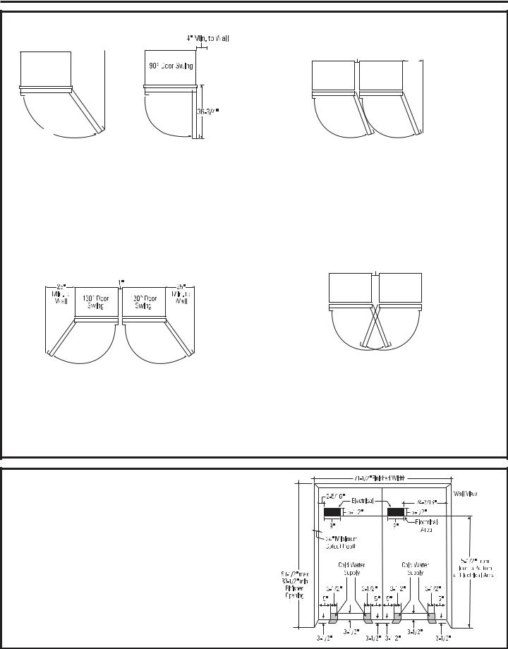
Clearances for Multiple Single Door Installations
In a side-by-side installation of a left and right door swing product, a 1” (2.54 cm) clearance between the units is required. Order ZUGSS2 Stainless Steel Unified Grille Panel Kit or ZUG2 Custom Panel Unified Grille Panel Kit for one continuous grille panel.
2" |
15" |
|
Clearances for two products installed side-by- side with the same (left or right) door swing
Allow 2” (5.08 cm) minimum clearance between the products to prevent door swing interference. Order the WX14X99 adjustable door stop to reduce the factory set 115° door swing. Allow 15” (38.1cm) minimum to a wall to achieve full drawer extension and pan removal.
NOTE: ZUG2 and ZUGSS2 Grille Panel Kit will NOT fit this installation.
5"
Clearances for two products installed side-by- side with right and left side hinges together Allow 5” (12.7 cm) minimum between the two products to prevent one door from striking the other. Use the WX14X99 adjustable door stop to reduce the factory set 115° door swing and to allow pan removal.
NOTE: ZUG2 and ZUGSS2 Grille Panel Kit will NOT fit this installation.
INSTALLATION
ZUG2, ZUGSS2 Unified Grille Panel Kit
•If you are installing two units, side by side, the installation space must be 71-1/2” (181.61 cm) wide.
NOTE: Additional cutout width may be required when side panels are used. Add side panel thickness to the finished cutout to calculate rough-in width.
•The water and electrical locations for each product must be located as shown.
•A separate 115V, 60Hz., 15 or 20 amp power supply is recommended for each product.
7
31-49140-1

Design Guide - Standard Installation
CUSTOMIZATION BASICS: Framed or Overlay Panels, Custom Handles and Accessory Kits
Trimmed models are designed to be customized with decorative panels. Field installed custom door and grille panels are required.
Optional Accessory Kits
•ZKHSS2: Monogram Tubular Stainless Steel handles designed to fit 3/4” (1.9 cm) overlay panels.
•ZKHPSS1: Pro Tubular Stainless Steel handle designed to fit 3/4” (1.9 cm) overlay panels.
•ZUG2: For side-by-side installation of two trimmed models. This kit provides for the installation of a unified custom grille panel to span the width of two units using a framed or overlay panel.
REFRIGERATOR LOCATION
•Do not install the refrigerator where the temperature will go below 55°F (13°C). It will not run often enough to maintain proper temperatures.
•Do not install the refrigerator where temperatures will go above 100°F (37°C). It will not perform properly.
•Do not install the refrigerator in a location exposed to water (rain, etc.) or direct sunlight.
•Install it on a floor strong enough to support it fully loaded.
8
31-49140-1
Design Guide - Standard Installation
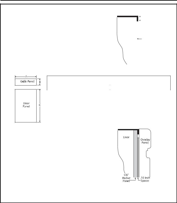
1/4” (0.63 cm) FRAMED PANEL DIMENSIONS
If you choose to install framed panels, they must be cut to the |
|
|
|
|
|
|
5/16" |
|
|
|
|
|
|
||
dimensions shown. The panels will slide into the frame on the door |
|
|
|
|
|||
|
|
|
|
|
|||
|
|
|
|
|
|
Trim |
|
|
|
|
|
|
|||
and grille. |
Door |
|
|
|
Reveal |
||
If the custom panel is less than 1/4” (0.63 cm) thick and if it fits |
|
|
|
|
|
|
|
loosely in the door frame, it can be backed up with a piece of filler |
|
|
|
|
|
|
|
material or foam tape to improve the fit. |
|
|
1/4" |
||||
IMPORTANT NOTE: Maximum weight for door panel is 67 pounds |
|
|
|
|
Panel |
||
(30.39 kg). Maximum total weight for assembled grille panel is 11 |
|
|
|
|
|
|
|
pounds (4.99 kg). |
|
|
|
|
|
|
|
|
|
|
|
|
|
|
|
Framed Panel Dimensions
1/4” (0.63 cm) |
A (Width) |
B (Grille Height) |
C (Door Height) |
Framed Panel |
33-7/8” (86.04 cm) |
8-7/8” (22.54 cm) |
69-5/16”(176.05 cm) |
|
|
|
|
Overlay Panel Dimensions |
|
|
|
1/4” (0.63 cm) |
A (Width) |
B (Grille Height) |
69-5/16”(176.05 cm) |
Backer Panel |
33-7/8” (86.04 cm) |
8-7/8” (22.54 cm) |
69-5/16”(176.05 cm) |
0.10” (0.25 cm) |
32-1/2” (82.55 cm) |
7-5/8” (20 cm) |
67-15/16” |
Spacer Panel |
|
|
(172.56 cm) |
3/4” (1.9 cm) |
34-1/8” (96.67 cm) |
9” (22.86 cm) |
69-9/16” |
Overlay Panel |
|
|
(176.69 cm) |
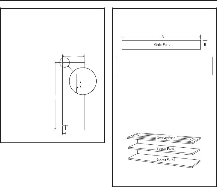
3/4” (1.9 cm) OVERLAY PANEL DIMENSIONS
For a more custom appearance, overlay panels may be installed on trimmed models. The overlay panel must be secured to a 1/4” (0.63 cm) thick backer panel which slides into the trim. A spacer panel 0.10” (0.25 cm) thick must be placed between the overlay and backer panel.
IMPORTANT NOTE: Maximum total weight for assembled door panel is 67 pounds (30.39 kg). Maximum total weight for assembled grille panel is 11 pounds (4.99 kg).
Assemble the panels with glue and screws.
•Center the spacer panel on the backer panel, left to right and top to bottom. Secure the panels with glue.
•Center the spacer and backer panel on the overlay panel and secure with glue and screws. Screws must be countersunk into the backer panel.
NOTE: Left-to-right offset is not always equal to top-to-bottom offset.
9
31-49140-1
Design Guide - Standard Installation
SIDE PANELS
Side panels must be used whenever the sides of the unit will be exposed. The 1/4” (0.63 cm) side panels will slip into the side case trim. Secure the panels to the unit with stick-on hook and loop fastener strips.
Order the side panels from the cabinet manufacturer.
•Cut a notch in the top front corner as shown to allow clearance for corner keys in the front side trim.
24"
* Depending on installation height.

 3/16"
3/16"  1-7/8"
*84"
 *3" to 4"
 2-9/16"
ZUG2 GRILLE PANEL DIMENSIONS
The ZUG2 unified grille panel kit provides for the installation of a framed or overlay grille panel.
Framed Panel Dimensions
1/4” (0.63 cm) |
A (Width) |
B (Height) |
Framed Panel |
69-7/8” (177.48 cm) |
8-7/8” (22.54 cm) |
|
|
|
Overlay Panel Dimensions |
|
|
1/4” (0.63 cm) |
A (Width) |
B (Grille Height) |
Backer Panel |
69-7/8” (177.48cm) |
8-7/8” (22.54 cm) |
0.10” (0.25 cm) |
68-1/2” (97.79 cm) |
7-5/8” (20 cm) |
Spacer Panel |
|
|
3/4” (1.9 cm) |
70-1/8” (178.12 cm) |
9” (22.86 cm) |
Overlay Panel |
|
|
IMPORTANT NOTE: The maximum weight for the unified grill is 25 pounds (11.24 kg).
Assemble the overlay panels in the same manner as the door panel.
10
31-49140-1

Design Guide - Standard Installation
Frameless Cabinets: The case trim overlaps cabinets at the top and sides. Therefore, frameless cabinets may require filler strips to prevent interference with cabinet door swing. The opening must allow for filler strips.
Top View
130° DOOR SWING
Scale 1:1
11
31-49140-1
Installation Instructions - Standard Installation
TOOLS AND MATERIALS REQUIRED
•Tin snips to cut banding
•#2 Phillips screwdriver
•Stepladder
•Drill and 1/2”, 3/16” bits
•Bucket
•1/4”, 1/2”, 5/16”, 7/16” socket
•Level
•Safety glasses
•Appliance hand truck
•Pliers
•Tubing cutter
•Stud finder
•7/16” and 1-1/4” open-end wrench
•1/4” copper water line tubing or SmartConnect™ Refrigerator Tubing kits
•Water shut-off valve (optional but recommended)
•Custom panels for door and grille panel
•Screws to secure unit to cabinetry
•Stick-on hook and loop fastener strips for 1/4” (0.63 cm) side panels
GROUNDING THE UNIT

 WARNING
 Electrical Shock Hazard.
Failure to follow these instructions can result in death, fire, or electrical shock.
The power cord of this appliance is equipped with a 3-prong (grounding) plug which mates with a standard 3-prong (grounding) wall receptacle to minimize the possibility of electric shock hazard from this appliance.
Have the wall outlet and circuit checked by a qualified electrician to make sure the outlet is properly grounded.
Where a standard 2-prong wall outlet is encountered, it is your personal responsibility and obligation to have it replaced with a properly grounded 3-prong wall outlet.
DO NOT, UNDER ANY
CIRCUMSTANCES, CUT OR REMOVE THE THIRD (GROUND) PRONG FROM THE POWER CORD.
DO NOT USE AN ADAPTER PLUG TO CONNECT THE REFRIGERATOR TO A 2-PRONG OUTLET.
DO NOT USE AN EXTENSION CORD WITH THIS APPLIANCE.
HARDWARE SUPPLIED
•Water filter bypass plug
•Anti-Tip brackets
•3 lag screws
•2 Hair Pin Cotters
•4 washers
•5 toggles with bolts
•Toekick
FLOORING
For proper installation, this product must be placed on a level surface of hard material that is at the same height as the rest of the flooring. This surface should be strong enough to support a fully loaded refrigerator or freezer, or approximately 1,200 lbs. per unit.
NOTE: Protect the finish of the flooring. Cut a large section of the cardboard carton and place under the product where you are working.
NOTE: Not recommended for installation on carpeted flooring.
LA TERRE DE L’UNITÉ

 AVERTISSEMENT
 Risque de choc électrique.
Le non-respect de ces instructions peut entraîner des risques d’incendies, des chocs électriques ou la mort.
Le cordon d’alimentation de cet appareil est équipé d’une fiche à trois broches (pour une mise à la terre) qui s’adapte à la prise de courant standard à 3 broches (pour une mise à la terre) pour minimiser les risques de chocs électriques par cet appareil.
Faites vérifier la prise murale et le circuit électrique par un électricien qualifié pour s’assurer que le système est correctement mis à la terre.
Dans le cas d’une prise biphasée, l’installateur a la responsabilité et l’obligation de la remplacer par une prise triphasée correctement mise à la terre.
NE COUPEZ PAS OU N’ENLEVEZ
PAS, SOUS AUCUN PRÉTEXTE, LA TROISIÈME BROCHE DE MISE À LA TERRE DU CORDON D’ALIMENTATION.
N’UTILISEZ PAS D’ADAPTATEUR POUR BRANCHER LE RÉFRIGÉRATEUR À UNE PRISE BIPHASÉE.
N’UTILISEZ PAS DE RALLONGE AVEC CET APPAREIL.
12
31-49140-1
Installation Instructions - Standard Installation
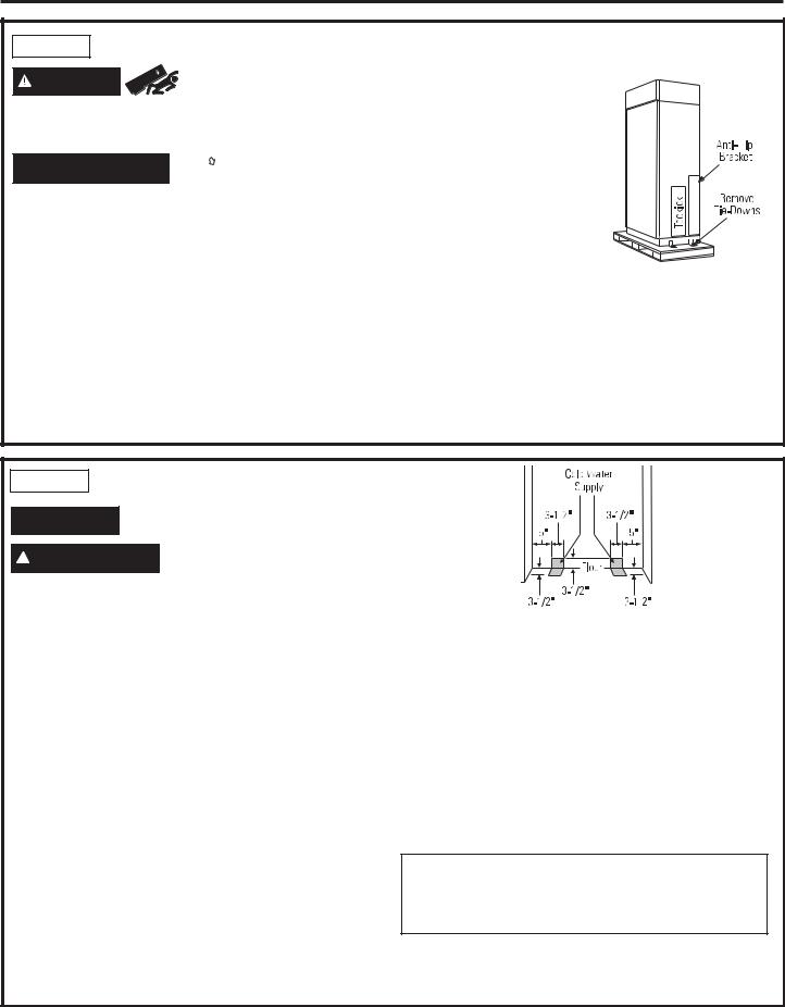
STEP 1 REMOVE PACKAGING
WARNING |
Tip Over Hazard. Product |
|
|
is much heavier at the top than at the bottom – be |
|
careful when moving. When using a hand truck, handle from side only.

 AVERTISSEMENT

 Risque de basculement
Le produit est beaucoup plus lourd en haut qu’en bas. Il faut être prudent lors des déplacements. Si un diable est utilisé, il faut soulever le réfrigérateur sur le côté
seulement.
•Carefully cut banding at the top and bottom, remove outer carton.
•Slide out back corner posts (2).
•Slide carton off top of cabinet.
NOTE: IT IS NOT NECESSARY TO LAY CABINET DOWN
IN ORDER TO REMOVE SKID!
NOTE: DO NOT ATTEMPT TO ROLL UNIT OFF SKID.
•The unit is secured to the skid with 4 slotted tie-down straps. Remove the four 5/16” bolts from the base channels in the
tie-downs.
• Unit is shipped with two sets of toe kicks. One for Flush Inset (longer) and One for standard installation (shorter). Pick proper toe kick for your installation. Discard other toe
kick.
•Remove toekick, custom handle trim, and wall bracket. Set aside for final installation.
•Lift the unit off the skid with an appliance dolly. Handle from the sides.
•Remove the four 7/16” bolts securing the tie-down brackets to the skid.
STEP 2 INSTALL WATER LINE

 WARNING Connectonly. to potable water supply
 AVERTISSEMENT Raccordez l’appareil à une alimentation d’eau potable seulement.
•A cold water supply is required for automatic icemaker and AutoFill pitcher operation. The water pressure must be between 40 and 120 p.s.i. (275-827 kPa).
•Route 1/4” OD copper or SmartConnect™ plastic tubing between house cold water line and the water connection location.
•Tubing should be long enough to extend to the front of the unit. Allow enough tubing to accommodate bend leading into the water line connection.
NOTE: The only Monogram approved plastic tubing is supplied in the SmartConnect™ Refrigerator Tubing kits. Do not use any other plastic water supply line because the line is under pressure at all times. Other types of plastic may crack or rupture with age and cause water damage to your home.
SmartConnect™ Refrigerator Tubing Kits are available in the following lengths:
2’ (.6 m) WX08X10002 8’ (2.4 m) WX08X10006 15’ (4.6 m) WX08X10015 25’ (7.6 m) WX08X10025
Shut off the main water supply.
Turn on the nearest faucet long enough to clear the line of water.
•Install a shut-off valve between the icemaker water valve and cold water pipe in a basement or cabinet.
The shut-off valve should be located where it will be easily accessible.
•Turn on the main water supply and flush debris. Run about a quart of water through the tubing into a bucket. Shut off water supply at the shut-off valve.
NOTE: Saddle type shut-off valves are included in many water supply kits. Before purchasing, make sure a saddle type valve complies with your local plumbing codes.
NOTE: Commonwealth of Massachusetts Plumbing Codes 248CMR shall be adhered to. Saddle valves are illegal and use is not permitted in Massachusetts. Consult with your licensed plumber.
13
31-49140-1
Installation Instructions - Standard Installation
STEP 3 INSTALL SIDE PANELS
Skip this step when not using side panels
If you are using 1/4” side panels, they should be inserted into the case trim.
Fasten the panels to the unit with stick-on hook and loop fastener strips before setting unit in place.
STEP 4 INSTALL ANTI-TIP BRACKET

 WARNING

 Tip Over Hazard.
The unit is top-heavy and must be secured to prevent the possibility of tipping forward.

 AVERTISSEMENT

 Risque de basculement
L’appareil ménager est beaucoup plus lourd en haut et il faut le maintenir en place pour éviter la possibilité de son basculement vers l’avant.
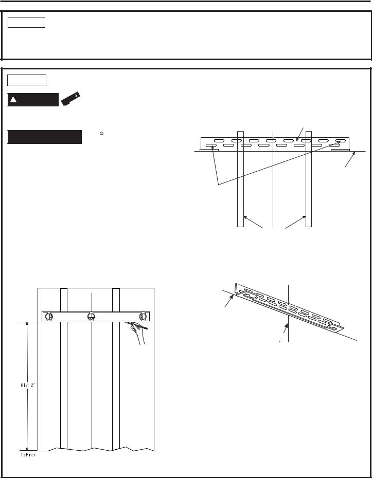
•The kit supplied with the unit contains 2 lag bolts and 4 toggles with bolts. The wall bracket will be attached to the wall in 4 places.
•Measure the opening where the unit is to be installed. Mark the center with a vertical line.
•Measure up 81-1/2” (207.01 cm) from the floor. Mark this point on the wall.
•Using a level, draw a horizontal line on the wall at this height.
•Locate at least 2 studs on the back wall. Mark these points on the horizontal line.
•Place the bottom of the wall bracket with tabs on the horizontal line. Align the center notch on the bracket with the center line on the wall.
Center |
Wall Bracket |
|
Line On Wall
Two Additional
Hole Locations at
Ends of Brackets
Wall Studs
•The anti-tip wall bracket has a series of holes. Select 2 holes that match with the located studs. Make sure the holes selected are on the center of the studs. Mark the wall at these points.
Line on Wall
Center
•Mark an additional hole at each end of the bracket. If one of the studs is closer to the end of the bracket, mark an additional hole towards the center of the bracket.
•Drill 1/2” (1.27 cm) holes into the wall board at the locations marked for the toggles to be mounted (not the stud markings).
•Drill 3/16” (0.47 cm) holes into wooden studs where marked. If steel stud construction, drill 1/2” (1.27 cm) holes into the studs where marked. You will use 2 toggles with the metal studs.
14
31-49140-1
Installation Instructions - Standard Installation
STEP 4 INSTALL ANTI-TIP BRACKET (cont.)
Install Wall Toggles:
The wall toggles and bolts can be ordered as Service Kit #WR49X10193. Wall toggles are installed in the drywall and metal studs for stability. Install the wall toggles as follows:
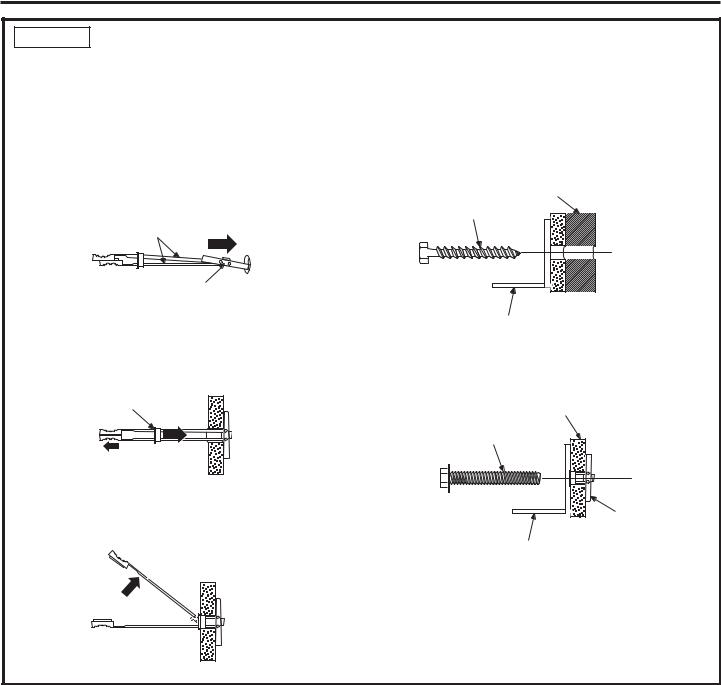
•Drill 1/2” (1.27 cm) holes at the wall markings made in the holes at the ends of the wall bracket.
•Hold the metal channel flat against the plastic straps and slide the channel through the hole.
Plastic Straps
Metal Channel
•Gently pull back at the ends of the plastic straps to make the channel rest flush behind the wall.
•Hold the ends of the straps in one hand and slide the plastic cap along the straps until the flange of the cap is flush with the wall.
Cap
•Place your thumb between the plastic straps and bend up and down to snap the straps off at the wall.
Install Screws and Bolts:
•Have someone hold the wall bracket centered in place with each of the holes aligned with the correct opening in the bracket and level with the horizontal line.
•Insert the lag screws through the bracket and into the stud. Tighten with a wrench.
•
Wood Stud
Lag Screw
Anti-Tip Wall Bracket
Insert the bolts into the toggle by hand until snug. Tighten with a wrench.
Drywall or
Steel Stud
Bolt
Wall Toggle
Anti-Tip Wall Bracket
15
31-49140-1
Installation Instructions - Standard Installation
STEP 4 INSTALL ANTI-TIP BRACKET (cont.)
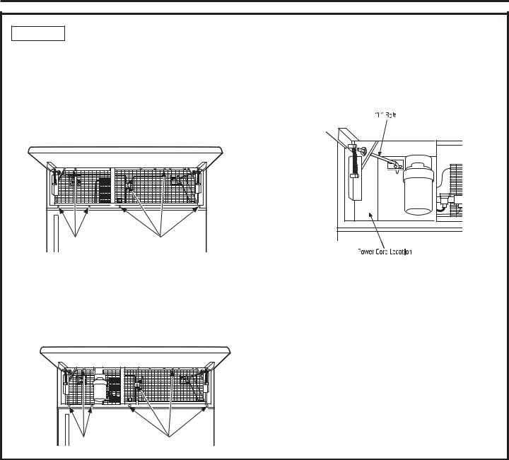
Remove Grilles for Access to Anti-Tip Locking Hooks
Fresh Food Unit
•Open the access door.
•Remove the 4 screws from the grille on the right and 3 screws from the grille on the left.
•Pull the bottom of the grilles forward, down and out to remove.
Screws |
Screws |
Freezer Unit
•Open the access door.
•Remove the 4 screws from the grille on the right and 3 screws from the grille on the left.
•Pull the bottom of the grille forward, down and out to remove.
Screws |
Screws |
Power Cord
Locate the power cord inside the left cavity. If it has not been adjusted so the plug is easily accessible, do so now.
Move Unit into Final Position
•Move appliance toward its final installed location. Align the tabs on the wall bracket with the openings in the back of the unit.
•The unit has “L” bolts in the upper left and right corners inside of the access compartment. These bolts will interlock with the wall bracket and secure the unit using the washers and hair pin cotters in the hardware kit once the unit has been leveled and is in the final position.
16
31-49140-1
 Loading...