


GE ZGU364LDP1SS, ZGU364LDP2SS, ZGU364LDP3SS, ZGU364LRP1SS, ZGU364LRP2SS Installation Guide
...Installation
Instructions
36” and 48” Professional Rangetops
Tables de cuisson professionnelles de 36” (91 cm) et de 48” (122 cm)
Instructions d’installation
La section française commence à la page 18
Estufas profesionales
de 36” (91 cm) y 48” (122 cm)
Instrucciones de instalación
La sección en español empieza en la página 34
31-10691-5
12-13 GE

Safety Information
BEFORE YOU BEGIN
Read these instructions completely and carefully.
• IMPORTANT³ Save these instructions for local inspector’s use.
• IMPORTANT³Observe all governing codes and ordinances.
•Note to Installer³Be sure to leave these instructions with the Consumer.
•Note to Consumer³ Keep these instructions with your Owner’s Manual for future reference.
•Completion Time³1 to 3 hours.
•Proper installation is the responsibility of the installer. Product failure due to improper
installation is not covered under the warranty. See Owner’s Manual for warranty information.
 WARNING
This appliance must be properly grounded. Follow directions in ”Electric Supply” of this manual. Failure to do so may result in electric shock.
For Monogram local service in your area, 1.800.444.1845.
For Monogram Service in Canada, call 1.800.561.3344.
For Monogram Parts and Accessories, call 1.800.626.2002.
If you received a damaged rangetop, you should contact your dealer.
In the Commonwealth of Massachusetts:
•This product must be installed by a licensed plumber or gas fitter.
•When using ball type gas shut off valves, they shall be T-handle type.
•A flexible gas connector, when used, must not exceed 3 feet.
If sold outside the U.S. and Canada:
 WARNING: If you wish to use this product with Liquefied Petroleum (LP) gas containing greater than 10% butane, you must purchase the butane conversion kit #WB28K10589. To order, please call 1.888.664.8403 or 1.787.276.4051. Failure to do so may result in carbon monoxide or fire hazard.
Vent hood Combinations:
It is recommended that these rangetops be installed in conjunction with a suitable overhead vent hood.
•Install a hood with at least 1200 CFM above a 48” wide rangetop.
•Install a hood with at least 600 CFM above a 36” rangetop.
Due to the high heat capacity of this unit, particular attention should be paid to the hood and ductwork installation to assure it meets local building codes.
 WARNING:
Do not install this product with an air curtain hood or other range hood that operates by blowing air down on the cooktop. This airflow may interfere with operation of the gas burners resulting in fire or explosion hazard.
Clearances to horizontal surfaces above the range, measured to the cooking surface are below. Failure to comply may result in fire hazard.
•Installations without a hood require 48” minimum to combustibles.
•A custom hood installation with exposed horizontal combustibles surfaces must have an Auto-On feature.
•For other installations with a hood, refer to hood installation instructions for specific hood clearances.
 CAUTION:
These rangetops are extremely heavy. Due to the weight and size of the rangetop and to reduce the risk of personal injury or damage to the product:
TWO PEOPLE ARE REQUIRED FOR PROPER INSTALLATION.
Installation must conform with local codes. In the absence of local codes, the rangetop must comply with the National Fuel Gas Code, ANSIZ223.1/ NFPA 54, latest edition and National Electrical Code ANSI/NFPA 70 latest addition. In Canada, installation must conform with the current Natural
Gas Installation Code, CAN/CGA-B149.1 or the current Propane Installation Code, CAN/CGA-B149.2, and with local codes where applicable. This rangetop has been design-certified by CSA International according to ANSI Z21.1, latest edition and Canadian Gas Association according to CAN/CGA-1.1 latest edition.
Leak testing of the appliance shall be conducted according to the manufacturer’s instructions.
2
Design Information
CONTENTS
Design Information |
|
Installation Instructions |
|
|
Models Available...................................................................... |
3 |
Step 1, Cut the Countertop Opening.............................. |
9 |
|
Backsplash Accessories ....................................................... |
3 |
Step 2, Install the Rangetop............................................ |
10 |
|
Product Dimensions and Clearances |
|
Step 3, Connect Rangetop to Gas................................ |
10 |
|
for 48” Wide Models............................................................... |
4 |
Step 4, Connect Electrical................................................. |
11 |
|
Product Dimensions and Clearances |
|
Step 5, Check Burners ....................................................... |
11 |
|
for 36” Wide Models............................................................... |
5 |
Finalize Installation.............................................................. |
11 |
|
Installation Options ............................................................... |
6 |
Installation Checklist........................................................... |
11 |
|
Installation Preparation |
|
Install the Rangetop Backsplash Accessory............ |
12 |
|
|
Install the Adjustable |
|
||
Tools and Materials Required |
7 |
|
||
Backsplash Accessory |
13, 14 |
|||
Power Supply Locations |
7 |
|||
Gas Conversion |
15–17 |
|||
Remove Packaging |
8 |
|||
|
|
MODELS AVAILABLE
Monogram rangetops are factory set for natural |
36” Natural Gas Models: |
|
gas or LP gas. Order the model for your installation |
ZGU364ND – 4 gas burners and griddle |
|
situation. |
ZGU364NR – 4 gas burners and grill |
|
48” Natural Gas Models: |
||
ZGU366N – 6 gas burners |
||
ZGU484NG – 4 gas burners, grill and griddle |
36” LP Gas Models: |
|
ZGU486NR – 6 gas burners and grill |
||
ZGU486ND – 6 gas burners and griddle |
ZGU364LD – 4 gas burners and griddle |
|
ZGU364LR – 4 gas burners and grill |
||
48” LP Gas Models: |
||
ZGU366L – 6 gas burners |
||
ZGU484LG – 4 gas burners, grill and griddle |
|
|
ZGU486LR – 6 gas burners and grill |
|
|
ZGU486LD – 6 gas burners and griddle |
|
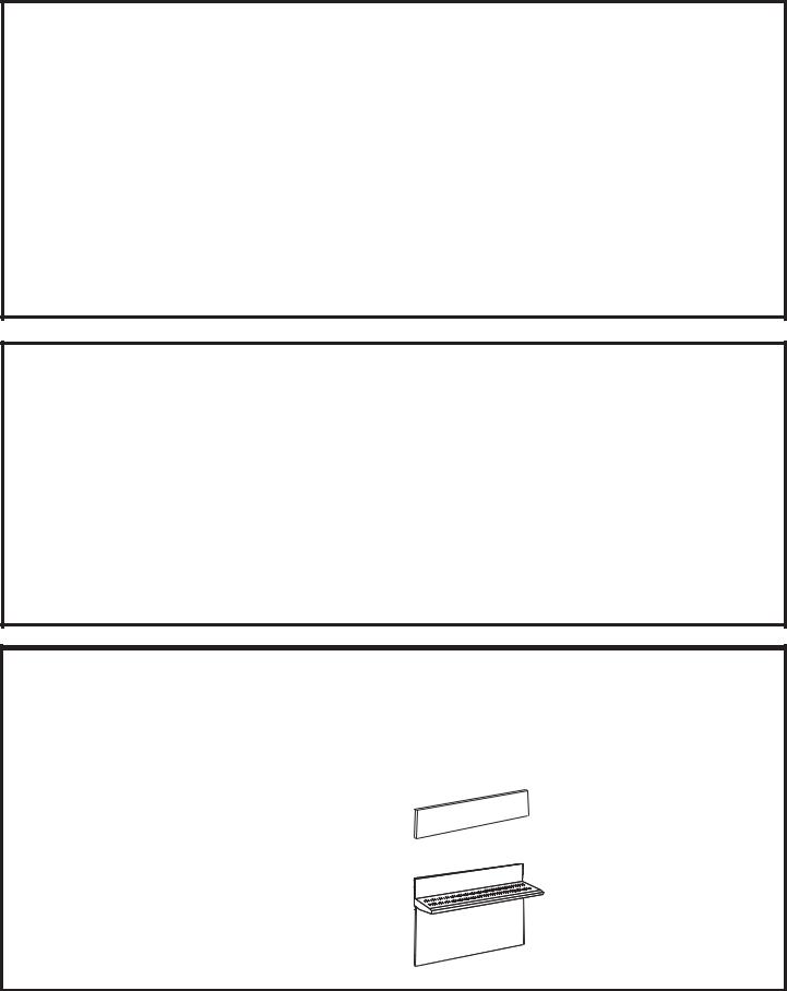
BACKSPLASH ACCESSORIES
All models require 12” minimum clearance to a vertical combustible surface at the rear. If clearance is less than 12”, the entire surface of the back wall above the countertop and the full width of the rangetop must be protected by a backsplash. The backsplash must be constructed of non-combustible material, such as metal, ceramic tile, brick, marble or other stone.
Two Backsplash Accessories Available:
•The 12” high stainless steel backsplash accessory is available. Use this backsplash in combination with a custom, non-combustible backsplash built beyond the 12” height. The combined height of the backsplash accessory and the custom backsplash must reach the bottom of a hood, or when there is no hood, to 48” above the cooking surface.
•An adjustable 30” to 36” high backsplash with shelf is also available. This backsplash fills in the space between the top of the rangetop and the bottom of the hood. The shelf is positioned so that heat lamps from the bottom of a Monogram professional hood are directed towards the shelf.
12” High Backsplash
ZX12B48PSS, for 48” wide rangetops ZX12B36PSS, for 36” wide rangetops
30” to 36” Adjustable Height Backsplash With Shelf
ZXADJB48PSS, for 48” wide rangetops ZXADJB36PSS, for 36” wide rangetops
3

Design Information
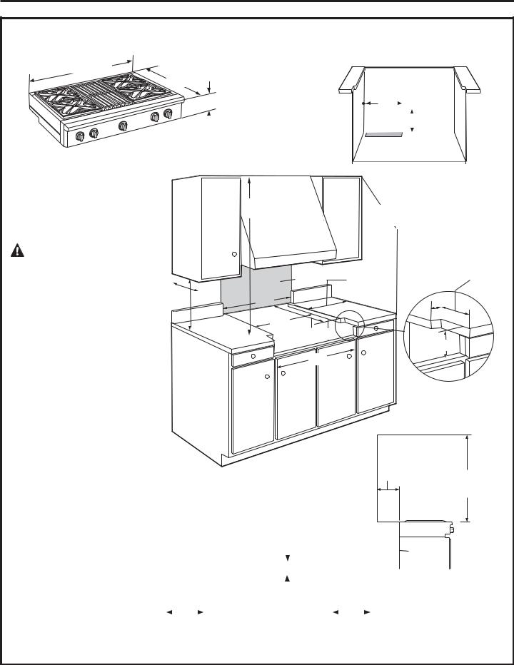
PRODUCT DIMENSIONS AND CLEARANCES FOR 48” MODELS
|
27-1/2” to |
|
Universal Utility Locations |
47-7/8” Width |
Front of |
|
|
Bullnose |
|
|
|
|
|
|
|
|
|
Locate gas |
2” |
|
|
17” |
|
|
|
inlet on back |
|
|
8-1/2” |
|
|
|
wall or on |
16” |
|
|
Height |
||
|
|
floor 2” from |
|
|
|
back wall. |
|
|
WARNING: |
|
|
|
|
|
|
|
|
|
|
|
|
|
|
Installations without a hood |
|
|
|
|
|
|
|
require 48” minimum to combustibles |
|
|
|
|
|
|
|
|
|
|
|
|
|
||
above the rangetop. A custom hood |
|
|
|
|
|
|
|
|
|
|
|
|
|
||
|
|
|
|
|
|
||
installation with exposed horizontal |
13” Max. |
|
|
||||
combustible surfaces must have |
|
|
|
|
|
|
|
|
|
|
|
|
|
||
an Auto-On feature. Refer to hood |
|
|
|
|
|||
|
|
|
18” Min. |
||||
|
|
||||||
installation instructions for specific |
|
|
|
|
|
|
|
|
|
|
|
|
|
||
hood clearances. |
|
|
|
|
|
|
|
The surface of the entire back wall above the countertop and below the hood must be covered with
a non-combustible material such as metal, ceramic tile, brick, marble or other stone.
* The opening between a 4” high backsplash must be 48” to allow the rangetop to slide back against the wall.
ADDITIONAL CLEARANCES:
48” Minimum |
|
|
|
12” Minimum to |
|
to Combustibles |
|
|
|
Adjacent Wall |
|
|
|
|
|
|
|
Non- |
|
|
combustible |
12” Minimum |
7/8” |
material |
Each Side |
|
|
|
*48”
46-1/4”


22-3/4” Min.
8”
48”
12” Minimum to Combustibles or 0” to non-combustible material above the cooking surface
Allow 12” minimum clearance to an |
|
|
|
|
|
|
|
|
|
|
adjacent wall on each side. |
|
|
|
Back |
|
|
|
|
|
|
Working areas adjacent to the rangetop |
|
|
|
|
|
|
|
|
||
|
|
|
|
|
|
|
||||
|
|
|
2-1/2” Min. |
|
|
|
||||
should have 18” minimum clearance |
|
|
|
|
|
|
||||
between countertop and the bottom of |
|
|
|
|
|
|
|
|
|
0” |
|
|
|
|
|
|
|
|
|
||
the wall cabinet. |
|
|
|
|
|
|
|
|
|
|
|
|
|
|
|
|
|
|
|
Clearance |
|
For island installation, maintain 2-1/2 |
|
|
|
|
|
|
|
|
|
|
|
3” Min. |
|
|
|
|
3” Min. |
||||
in. minimum from cutout to back edge |
|
Island |
|
|||||||
of countertop and 3 in. minimum from |
|
|
|
Cutout |
|
|
|
|
||
cutout to side edges of countertop (see |
|
|
|
Top View |
|
|
|
|
||
top view). |
|
|
|
|
|
|
|
|
|
|
|
|
|
|
|
|
|
|
|
|
|
2-1/2”
48” Min. to Combustibles
4
Design Information
PRODUCT DIMENSIONS AND CLEARANCES FOR 36” MODELS
Universal Utility Locations
35-7/8” Width |
27-1/2” to |
|
Front of |
|
Bullnose |
|
|
Locate gas |
|
|
|
|
2” |
|
|
|
|
|
|||||||||
|
|
|
|
|
|
|
|
|
|||||||||||||
|
|
|
|
|
17” |
|
|
|
|
|
|
|
|
|
|
||||||
|
|
inlet on back |
|
|
|
|
|
|
|
|
|
|
|
|
|||||||
|
|
|
|
|
|
|
|
|
|
|
|
|
|
|
|
||||||
|
|
wall or on |
|
|
|
|
|
|
|
|
|
|
|
|
|
||||||
|
|
|
|
|
|
|
|
|
|
|
16” |
|
|
|
|||||||
8-1/2” |
|
|
|||||||||||||||||||
|
|
|
|
|
|
|
|
|
|
||||||||||||
floor 2” from |
|
|
|
|
|
|
|
|
|
|
|
|
|
|
|
||||||
Height |
|
|
|
|
|
|
|
|
|
|
|
|
|
|
|||||||
back wall. |
|
|
|
|
|
|
|
|
|
|
|
|
|
|
|||||||
|
|
|
|
|
|
|
|
|
|
|
|
|
|
|
|
||||||
|
|
|
|
|
|
|
|
|
|
|
|
|
|
|
|
|
|
|
|
|
|
|
|
|
|
|
|
|
|
|
|
|
|
|
|
|
|
|
|
|
|
|
|
|
|
|
|
|
|
|
|
|
|
|
|
|
|
|
|
|
|
|
|
|
|
|
WARNING: |
|
|
|
|
|
|
|
|
|
|
|
|
|
|
|
|
Installations without a hood |
|
|
|
|
|
|
|
|
require 48” minimum to combustibles |
|
|
|
|
|
|
|
|
|
|
|
|
|
|
|
||
above the rangetop. A custom hood |
|
|
|
|
|
|
|
|
|
|
|
|
|
|
|
||
installation with exposed horizontal |
13” Max. |
|
|
|
||||
|
||||||||
combustible surfaces must have |
|
|
|
|
|
|
|
|
|
|
|
|
|
|
|
||
an Auto-On feature. Refer to hood |
|
|
|
|
||||
|
|
|
18” Min. |
|||||
|
|
|||||||
installation instructions for specific |
|
|
|
|
|
|
|
|
|
|
|
|
|
|
|
||
|
|
|
|
|
|
|
||
hood clearances. |
|
|
|
|
|
|
|
|
The surface of the entire back wall above the countertop and below the hood must be covered with a noncombustible material such as metal, ceramic tile, brick, marble or other stone.
* The opening between a 4” high backsplash must be 36” to allow the rangetop to slide back against the wall.
ADDITIONAL CLEARANCES:
48” Minimum to Combustibles
Noncombustible material
*36”
35”
22-3/4” Min.
36”
12” Minimum to Adjacent Wall
12” Minimum |
1/2” |
||
Each Side |
|
|
|
|
|
|
|
|
|
|
|
|
|
|
|
8”
12” Minimum to Combustibles or 0” to non-combustible material above the cooking surface
Allow 12” minimum clearance to an |
|
|
|
|
|
|
|
|
|
0” |
adjacent wall on each side. |
|
|
|
|
|
|
|
|
|
|
Working areas adjacent to the rangetop |
|
|
|
Back |
|
|
|
|
|
Clearance |
|
|
|
|
|
|
|
|
|||
|
|
|
|
2-1/2” Min. |
|
|
|
|||
should have 18” minimum clearance |
|
|
|
|
|
|
|
|||
between countertop and the bottom of |
|
|
|
|
|
|
|
|
|
|
|
|
|
|
|
|
|
|
|
|
|
the wall cabinet. |
|
|
|
|
|
|
|
|
|
|
For island installation, maintain 2-1/2 |
|
3” Min. |
|
|
|
|
3” Min. |
|||
in. minimum from cutout to back edge |
|
|
Island |
|
||||||
of countertop and 3 in. minimum from |
|
|
|
|
Cutout |
|
|
|
|
|
cutout to side edges of countertop (see |
|
|
|
|
Top View |
|
|
|
|
|
top view). |
|
|
|
|
|
|
|
|
|
|
|
|
|
|
|
|
|
|
|
|
|
2-1/2”
48” Min. to Combustibles
5
Design Information
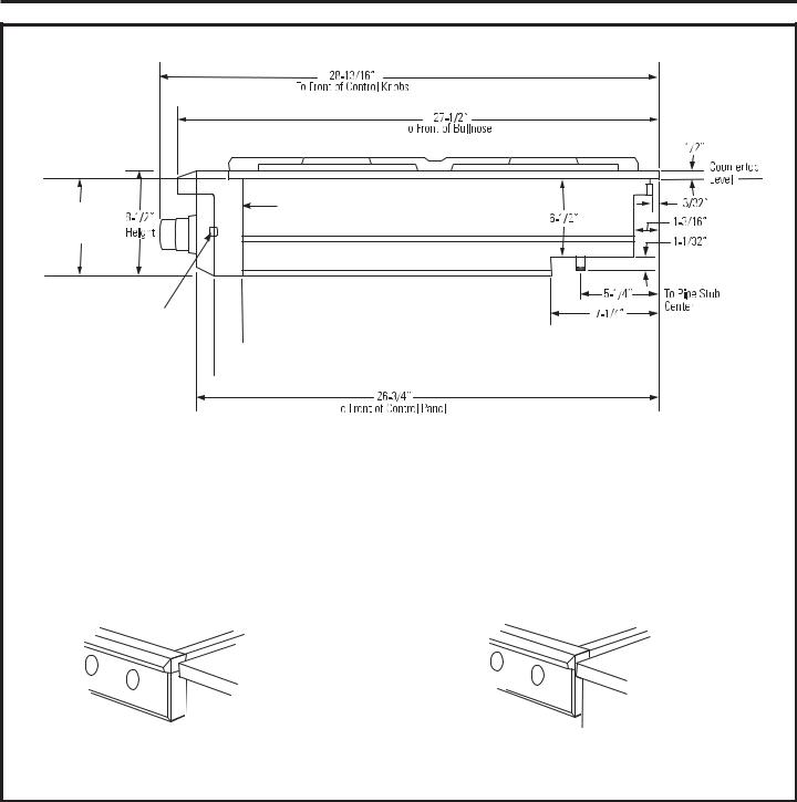
INSTALLATION OPTIONS
8” |
Finished back edge |
† |
of control panel |
|
|
Countertop |
|
|
Level |
|
|
Back edge
of chamfer
 *
* 


 **
** 


† Include the overhang of the rear trim when countertop continues behind the
 product.
 The overhang is decorative only. The weight of the rangetop is fully supported by the side trims.
* Minimum cabinet cutout depth from the back of the rear trim to the back finished edge of the control panel - typically, the minimum cabinet depth (front to back). Maximum cabinet cutout depth is 26” minus the countertop overhang.
Rangetop
Cooktop
1/2”” Abovee Adjacent
Countertops
Countertops.
** Maximum countertop cutout depth from the back of the rear trim
to the back edge of chamfer at the sides of the control panel - typically, the maximum countertop cutout depth (front to back). Minimum countertop cutout depth is 25-1/4”.
Rangetop
Cooktop
1/2”AboveAdjacent
Countertops.
Control panel projects forwards from standard depth cabinets.
Front of deep cabinets can align with control panel beveled edge.
6
Installation Preparation
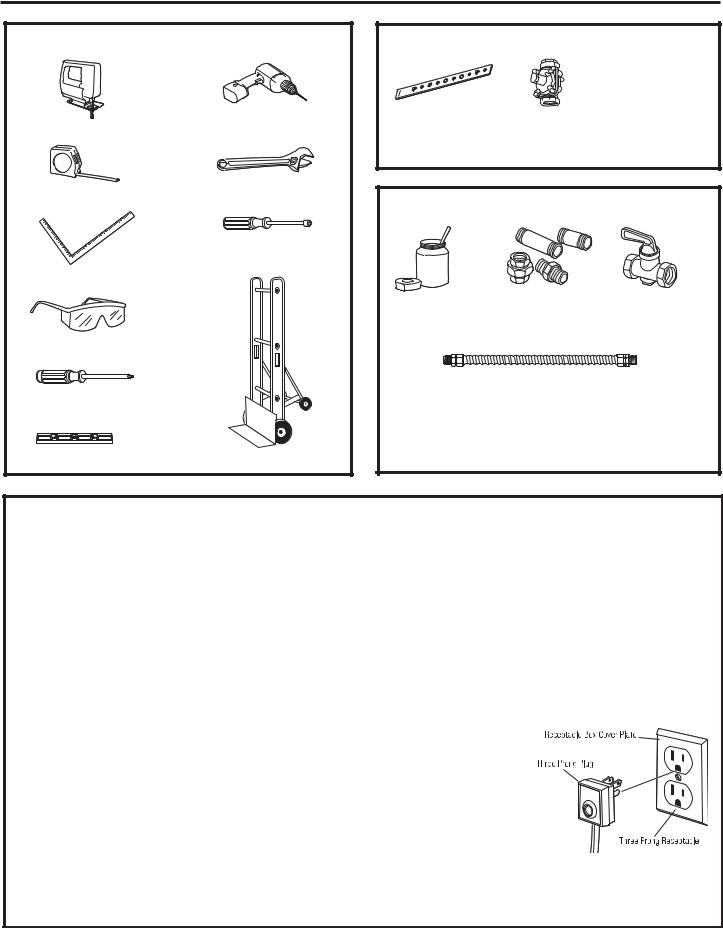
TOOLS REQUIRED
|
Drill and |
Saber Saw |
Appropriate Bits |
|
|
Measuring Tape |
Adjustable Wrench |
|
|
|
1/4” Driver or |
|
Wrench |
Carpenter’s Square |
|
Safety Glasses
Phillips #2
Screwdriver
Level |
Hand Truck |
|
MATERIALS PROVIDED
|
|
|
|
|
|
|
|
|
|
|
|
|
|
|
|
|
|
|
|
|
|
|
|
|
|
|
|
|
|
|
|
|
|
|
|
|
Regulator |
||||
Hold-Down |
|
|||||
|
|
|
|
|
|
|
Strap |
|
|
|
|
|
|
MATERIALS REQUIRED (not provided)
|
|
|
|
|
|
|
|
|
Joint |
|
|
|
|
|
|
|
|
|
|
|
|
|
|
|
Shut-Off |
|
|
|
|
Pipe Fittings |
|
||||
Sealant |
|
|
|
|
|
|
|
Valve |
|
|
|
|
|
|
|
|
|
|
|
|
|
|
|
|
|
|
5-foot maximum length, 5/8” O.D. CSA-approved flexible metal gas supply
(3-foot maximum length in Massachusetts only)
NOTE: Purchase new flexible line; do not use previously used flexible gas line.
POWER SUPPLY LOCATIONS
Gas Supply:
•The natural gas models are designed to operate at 5” water column pressure. For proper operation, the pressure of the natural gas supplied to the regulator must be between 7” and 13” water column.
•The LP models are designed to operate at 10” water column pressure. For proper operation, the pressure
of the LP gas supplied to the regulator must be between 11” and 13” water column.
•Locate the pipe stub on the back wall or floor
(see “Product Dimensions and Clearances”). Use 5-foot maximum length, 5/8” O.D. flexible gas supply line (3-foot in Massachusetts).
•Install a manual shut-off valve in the gas line
(not provided), in an easily accessible location. Make sure the homeowner knows where and how to shut off the gas supply to the rangetop.
Electric Supply:
These rangetops must be supplied with 120 volt, 60 Hz., and connected to a dedicated, properly grounded branch circuit protected by a 15 amp circuit breaker or time delay fuse.
The power cord of this appliance is equipped with a three-prong (grounding) plug which mates with a standard three-prong grounding wall receptacle to minimize the possibility of shock hazard from this appliance.
If the electrical service provided does not meet the above specifications, it is recommended that a licensed electrician install an approved outlet.
DO NOT, UNDER ANY CIRCUMSTANCES, CUT
OR REMOVE THE THIRD
(GROUND) PRONG FROM THE POWER CORD.
DO NOT USE AN EXTENSION CORD WITH THIS APPLIANCE.
• Locate the electric supply within the area shown or
within reach of the rangetop’s four-foot power cord.
•To avoid tangling cord with items stored in the cabinet, locate the receptacle on rear wall, inside the cabinet.
7
Installation Preparation
REMOVE PACKAGING
 CAUTION
Stand clear. The ends of the cut metal banding may snap toward you.
•Cut the metal banding.
•Remove packaging tape and foam. Dispose of packaging materials properly.
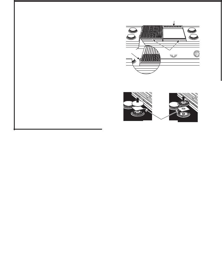
•Remove grill/griddle covers, grill grate and burner grates.
•Lift out cast-iron griddle flue cover, grease troughs and pads.
•Cut the ties holding the grill grate to the grill frame.
Griddle Flue Cover
Ties 


 Grease Troughs
•Lift off burner caps and remove foam pad,
then lift off burner heads and remove foam pad.
Remove Foam Pads |
8
Installation
STEP 1 CUT THE COUNTERTOP OPENING
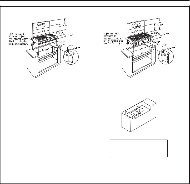
48” wide models are designed to fit in 48” or wider base cabinets
Measure carefully when cutting the countertop. Make sure sides of the opening are parallel.
•Allow 8” free space below the top surface of the countertop.
•Allow additional clearances below the burner box to install the regulator and make house supply connections. Use a 90° elbow to route the gas connections and limit interference with drawers or other cabinetry features.
•These rangetops are designed to hang from the countertop by their side flanges.
•Smooth any rough edges on the countertop before installing the rangetop.
– Formica countertop edges must be finished.
The countertop must be strong enough to support the weight of the rangetop.
36” wide models are designed to fit in 36” or wider base cabinets
Cutout Opening with False Bottom
Dimensions
|
A (Dia.) |
B |
C |
D |
36” Rangetop |
7-3/8” |
1-1/2” |
7-1/2” |
11-1/8” |
48” Rangetop |
8-1/4” |
1-1/2” |
7-1/2” |
11-1/8” |
|
|
|
|
|
•You can construct the cutout with a false bottom to conceal the bottom of the rangetop.
–Build the false bottom using a solid material; cut a 7-1/2” x 11-1/8” hole in the left rear corner for the gas inlet and power cord clearances.
9
Installation
STEP 2 INSTALL RANGETOP
•Slide the rangetop into the opening. Make sure the rangetop is evenly seated and supported.
•A hold-down strap with screws is provided to secure the rangetop to the rear or side cabinet walls.
•Remove the hold-down strap from the back of the rangetop. Attach one end of the strap to the back of the rangetop.
•Secure the other end of the strap as high as possible to the cabinet back wall or adjacent cabinet. Keep the strap as short as possible for better security.
Hold-Down
Strap
Location and
Attachment
Back Wall
STEP 3 CONNECT RANGETOP TO GAS
 WARNING
Do not use a flame to check for gas leaks.
A manual shut-off valve must be installed where it will be accessible.
Assure that gas is turned off at the shut-off valve.
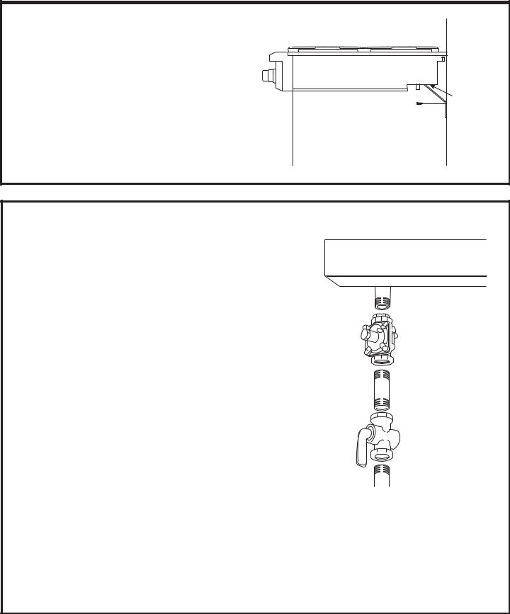
•Install the supplied pressure regulator onto the end of the gas inlet.
•You can install a 90° elbow (not provided) onto the gas inlet and route the gas connections to avoid interference with drawers or other cabinetry
features. However, it is not recommended because it will result in a drop in gas pressure.
•Make sure the regulator is installed in the right direction. See arrow on the underside of the regulator.
NOTE: Instead of using solid piping to connect to pressure regulator, an approved flexible metal appliance connector may be used between the pipe stub and the shut-off valve to the pressure regulator, if local codes permit.
•Turn on gas and check for leaks:
–Use a liquid leak detector at all joints and connections in the system.
Note: Pipe stub extends about 1” below burner box.
Rangetop Burner Box
1/2” N.P.T.
Gas Inlet
Regulator (Supplied)
Solid Piping or Flexible Connector
Shut-Off
 Valve
Valve
Pipe Stub From
House Gas Supply
IMPORTANT: Disconnect the rangetop and the individual shut-off valve from the gas supply piping system during any pressure testing of that system at test pressures greater than 1/2 psig. Isolate the rangetop from the gas supply piping system by closing the individual manual shut-off valve to the rangetop during any pressure testing of the gas
supply piping system at test pressures equal to or less than 1/2 psig.
10
Installation
STEP 4 CONNECT ELECTRICAL
•Plug power cord into properly grounded receptacle.
•Press the button on the left side of the control panel. The lights above the knobs should illuminate.
STEP 5 CHECK BURNERS
Check to be sure that burner heads and caps are securely seated.
FINALIZE INSTALLATION
Place the burner grates over the burners. The grates should be seated and should not rock.
The griddle is secured with screws. It is designed to be stationary and should not be removed.
The griddle has two leveling screws beneath the rear flue cover that can be used to adjust to the desired slope.
Griddle Flue Cover
Burner Cap Properly Seated |
Leveling Screws |
Burner Cap Not Properly Seated
•Check for proper ignition:
–Push in one control knob and turn to LITE position.
–The igniter will spark and the burner will light; the igniter will cease sparking when the burner is lit.
–First test may require some time, while air is flushed out of the gas line.
–Turn knob to OFF.
–Repeat the procedure for each burner.
IMPORTANT: If the igniter electrodes continue to spark after the burners are lit, check that each burner component is assembled properly. Refer to the Owner’s Manual.
•Burner flames should be blue and stable with no yellow tips, excessive noise or lifting of the flame from the burner. If any of these conditions exist, check that the burner ports are not blocked. If one of these conditions continues, call for service.
Clamping Screws
The two inner screws are clamping screws for securing the griddle in place. Loosen these two screws before leveling. Do not remove these two screws.
The two outer screws are leveling screws. Do not remove these two screws. They can be turned to level the griddle or to provide a forward slope to help grease and oils to drain away from the food being cooked.
After leveling the griddle, hand-tighten the clamping screws; do not over-tighten.
INSTALLATION CHECKLIST
■Make sure all controls are left in the OFF position.
■Make sure the flow of combustion and ventilation air to the rangetop is unobstructed.
■The serial plate for your rangetop is located on the bottom of the rangetop. In addition to the model and serial numbers, it tells you the ratings of the burners and the type of fuel and
pressure the rangetop was adjusted for when it left the factory.
■Recheck Steps:
Double check to make sure everything in this manual has been completed. Rechecking steps will ensure safe use of the rangetop.
11
 Loading...