


ZIS_420DM
GE ZIS_420DM, ZIS420NM, ZIS_360DM, ZIS360NM, ZIS480NM User Manual
...
g
PUB # 31-9091 03/02
MODEL SERIES:
TECHNICAL SERVICE GUIDE
GE Consumer Home Services Training
Monogram
Side-By-Side Refrigerators
With Electronic Controls
ZIS360NM
ZIS420NM
ZIS480NM
ZIS_360DM
ZIS_420DM
ZIS_480DM
GEA01265

IMPORTANT SAFETY NOTICE
The information in this service guide is intended for use by
individuals possessing adequate backgrounds of electrical,
electronic, and mechanical experience. Any attempt to repair a
major appliance may result in personal injury and property
damage. The manufacturer or seller cannot be responsible for the
interpretation of this information, nor can it assume any liability in
connection with its use.
WARNING
To avoid personal injury, disconnect power before servicing this
product. If electrical power is required for diagnosis or test
purposes, disconnect the power immediately after performing the
necessary checks.
RECONNECT ALL GROUNDING DEVICES
If grounding wires, screws, straps, clips, nuts, or washers used
to complete a path to ground are removed for service, they must
be returned to their original position and properly fastened.
GE Consumer Home Services Training
Technical Service Guide
Copyright © 2002
All rights reserved. This service guide may not be reproduced in whole or in part
in any form without written permission from the General Electric Company.
!

– 1 –
Technical Data ........................................................................................................................ 3
Model Nomenclature .............................................................................................................. 4
Rating Plate ...................................................................................................................... 4
Mini-Manual ....................................................................................................................... 4
Serial Number ...................................................................................................................5
Component Locator Views..................................................................................................... 6
Cabinet .................................................................................................................................... 9
Machine Compartment ..................................................................................................... 9
Door Closure Mechanism................................................................................................ 10
Doors and Hinges ............................................................................................................ 10
Door Gaskets..................................................................................................................... 11
Rollers and Leveling........................................................................................................11
Ice and Water Dispenser ...................................................................................................... 12
Controls ............................................................................................................................ 12
Water Valve and Water Tank ......................................................................................... 13
Airflow ................................................................................................................................... 14
Damper ............................................................................................................................ 14
Evaporator Fan ................................................................................................................ 15
Condenser Fan ................................................................................................................ 1 9
Defrost System ...................................................................................................................... 20
Adaptive Defrost .............................................................................................................. 20
Normal Operating Characteristics.................................................................................. 21
Abnormal Operating Characteristics ............................................................................. 21
Liner Protection Mode .................................................................................................... 21
Defrost Heater..................................................................................................................22
Evaporator Thermistor .................................................................................................... 23
Defrost Overtemperature Thermodisk ........................................................................... 23
Control System ...................................................................................................................... 24
Touch Panel and Temperature Control Board.............................................................. 24
Main Control Board ......................................................................................................... 25
Main Control Board Locator T ables............................................................................... 2 6
Thermistors ...................................................................................................................... 31
Climate Control Drawer........................................................................................................ 32
Strip Circuit...................................................................................................................... 32
Component Locator View............................................................................................... 33
Operation ......................................................................................................................... 34
Temperature Table .......................................................................................................... 35
Climate Control Drawer Top Panel (Mullion) ................................................................ 36
Control Board and Display ............................................................................................ 36
Fan and Fan Housing...................................................................................................... 38
Dampers ........................................................................................................................... 39
Heater............................................................................................................................... 40
Thermistor........................................................................................................................ 40
Airflow.............................................................................................................................. 42
Table of Contents

– 2 –
Table of Contents (cont.)
Compartment Lights ............................................................................................................. 44
FF/FZ Compartment Lights Diagnostic .......................................................................... 44
Door Switches ................................................................................................................. 45
Master Light Switch (Sabbath Switch) .......................................................................... 45
Temperature Overload Device (TOD)............................................................................. 45
Circuit Breakers............................................................................................................... 46
Transformers.................................................................................................................... 46
Light Bulb Replacement................................................................................................. 46
Schematic.............................................................................................................................. 49
Refrigeration System............................................................................................................ 50
Compressor...................................................................................................................... 50
Condenser........................................................................................................................ 50
Condenser Loop .............................................................................................................. 50
Dryer................................................................................................................................. 51
Evaporator ....................................................................................................................... 51
Refrigerant Charge ......................................................................................................... 51
Diagnostic Mode ................................................................................................................... 52
Diagnostic Flowcharts .......................................................................................................... 53
Fresh Food Warm - Freezer Normal.............................................................................. 53
Fresh Food Too Cold - Freezer Normal ......................................................................... 54
Fresh Food Warm - Freezer Warm ................................................................................ 55
Freezer Warm - Fresh Food Normal.............................................................................. 56
Compressor Not Running................................................................................................ 57
Refrigerator Dead - No Sound, No Cooling................................................................... 5 8
Damper Door Does Not Operate..................................................................................... 59
Heavy Frost on Evaporator ............................................................................................. 60
Evaporator Fan Not Running .......................................................................................... 61
Condenser Fan Not Running .......................................................................................... 6 2
Warranty ................................................................................................................................63
– 3 –
Technical Data
**
For model ZIS 36: WR55X10166. Model ZIS 36D: WR55X10165. Model ZIS 42:
WR55X10164. Model ZIS 42D: WR55X10163. Model ZIS 48: WR55X10162.
Model ZIS 48D: WR55X10158.
WARNING: Disconnect power cord before
servicing.
Note: Reconnect all grounding devices.
All parts of this appliance capable of conducting
electrical current are grounded. If grounding wires,
screws, straps, clips, nuts, or washers used to
complete a path to ground are removed for
service, they must be returned to their original
positions and properly fastened.
Caution: To avoid personal injury when servicing
the condensing unit, stand on a ladder which will
give enough support to allow removal of the top
panel and safely allow access to service the unit.
Max Defrost Control
W/No Door Openings ............60 hrs @ 35 min
Evap Overtemperature Thermodisc ..............60 °F-45 °F
Light Thermostat .....................................140 °F-90 °F
Electrical Rating: 115 VAC 60 Hz.....................9.0 amp
Maximum Current Leakage............................ 0.50 mA
Maximum Ground Path Resistance ............ 0.14 ohms
Energy Consumption (HUMID) ................................. *
CONTROL POSITION 37-0 °F and
AMBIENT TEMPERATURE OF
70 °F 90 °F
Fresh Food, °F ....................... 36–46 .............. 37–48
Frozen Food, °F ..................... (-6)–6 .............. (-4)–3
Percent Running Time............. 41–46 .............. 53–55
To access the low-pressure side of the system,
install a WR86X0097 valve only on the process
tube extending from the compressor case.
Important Safety Notice:
This information is intended for use by individuals
possessing adequate backgrounds of electrical,
electronic, and mechanical experience. Any attempt
to repair a major appliance may result in personal
injury and property damage. The manufacturer or
seller cannot be responsible for the interpretation
of this information, nor can it assume any liability in
connection with its use.
REFRIGERATION SYSTEM
Compressor ...............................................983 Btu/hr
Minimum Compressor Capacity
Vacuum .......................................... 26 inches
Minimum Equalized Pressure
@ 70 °F............................................ 72 PSIG
@ 90 °F.............................................88 PSIG
Refrigerant Charge (R134a) .............................14.50 oz
ELECTRICAL SPECIFICATIONS
NO LOAD PERFORMANCE
REFRIGERA TION DIAGNOSIS
HMI Temperature Control..........................................**
Relay ....................................................WR07X10031
Overload ............................................... WR08X10015
Run Capacitor (15 uF) ............................. WR62X0080
Overtemperature Thermodisc Light .......... WR50X10035
Overtemperature Thermodisc Evaporator .. WR50X10036
Defrost Heater ....................................... WR51X10065
Drain Trough ASM .................................. WR17X11194
Condenser Fan Motor ............................ WR60X10083
Condenser Fan Blade ............................ WR60X10049
Evaporator Fan Motor ............................ WR60X10043
Evaporator Fan Blade ............................ WR60X10050
Main Board ........................................... WR55X10167
Thermistors (2-FF , 1-FZ, 1-EV) ............... WR55X10025
Damper Assembly Fresh Food ............... WR60X10085
Evaporator ............................................ WR84X10038
Compressor .......................................... WR87X10042
Condenser............................................. WR84X10037
Filter Dryer ............................................. WR86X0096
*
For Models ZIS 36 & ZIS 36D: 51.2 kWh/mo. Models ZIS 42 & ZIS 42D:
54.6 kWh/mo. Model ZIS 48: 58.1 kWh/mo. Model ZIS 48D: 59.2 kWh/mo.
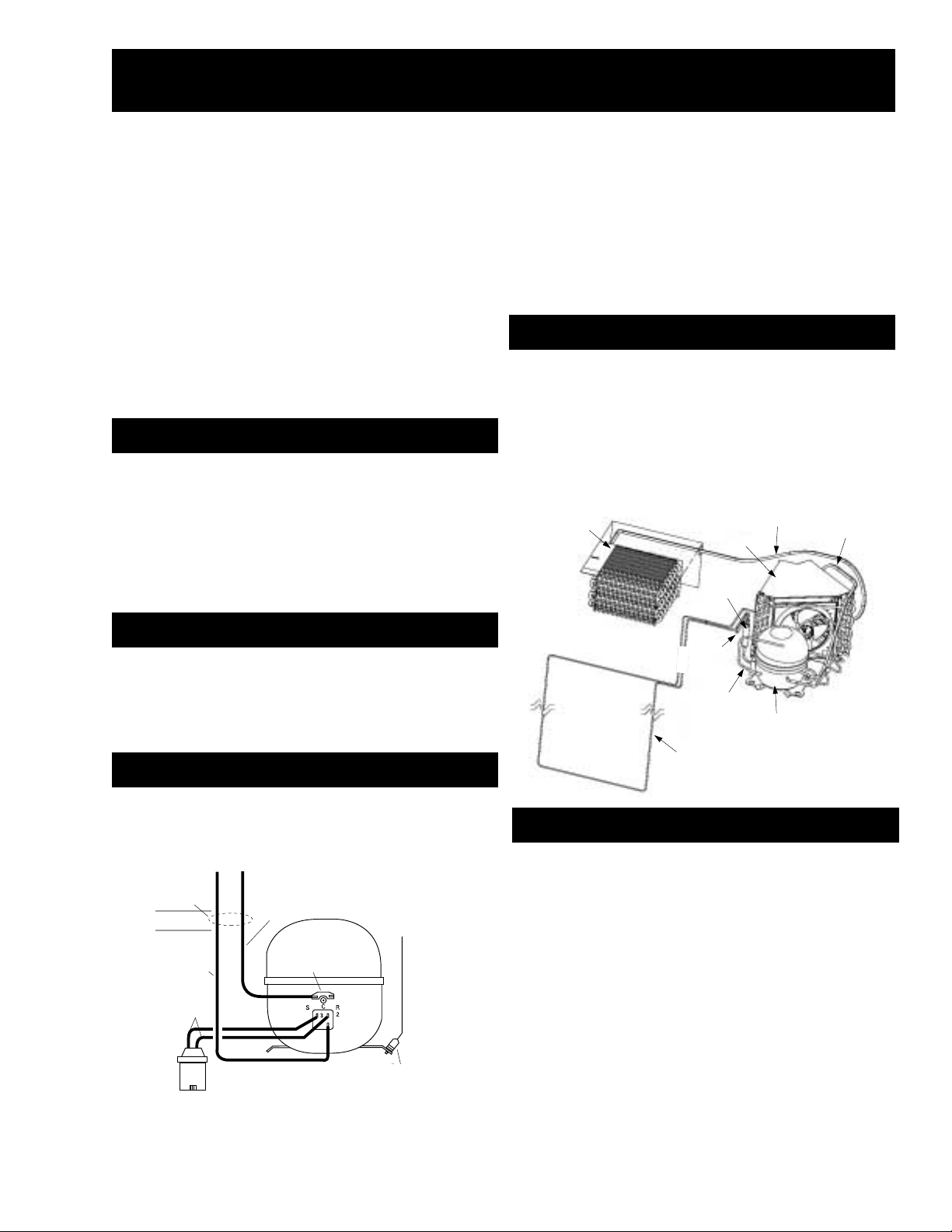
REPLACEMENT PARTS
Compressor
Process
Tube
High Pressure
(Do NOT use)
Evaporator
Heat Exchanger
Condenser
Suction
Tube
Condenser
Loop
Dryer
Overload
To Cabinet
Wiring
White
Orange
Black
Run
Capacitor
Green
(Ground)
To Cabinet
Wiring
White
Black
Overload
Green
(Ground)
Run Capacitor
Orange

– 4 –
Rating Plate
The rating plate, located behind the grille panel at
the top of the refrigerator on the right side of the
evaporator box, contains the model and serial
numbers. Additionally , the rating plate specifies
the minimum installation clearances, electrical
voltage, frequency, maximum amperage rating,
refrigerant charge, and type.
Mini-Manual
The mini-manual is located behind the grille
panel at the top of the refrigerator . When done,
return the mini-manual to its original location for
future use.
Brand/Product
Z - Monogram
Style
I - Built-In
Configuration
S - Side by Side
Color
S - Stainless B - Black W - White
Blank - Trim Model
Size
480 - 48 Inches Wide
Engineering
A - Initial Design
B - 1st Revision
C - 2nd Revision
D - 3rd Revision
Etc.
Door T ype
F - Flat
R - Right
L - Left Door Swing
Icemaker/Exterior
N - Nondispenser
Model Year
L - 2002 Pre-Energy
M - 2002 Energy
ZI
S
S
480
N
MA
LH
Model Nomenclature
Mini-Manual and
Rating Plate

– 5 –
Serial Number
The serial number consists of two letters, followed by six numerals. The two prefix letters of the
serial number indicate the month and year the product was manufactured. The year of manu-
facture does not correspond with the model year of the model number.
NAJBEFRAMRPAYAMNUJLUJGUAPESTCOVONCED
0002ZAZDZFZGZHZLZMZRZSZTZVZZ
1002AAADAFAGAHALAMARASATAVAZ
2002DADDDFDGDHDLDMDRDSDTDVDZ
3002FAFDFFFGFHFLFMFRFSFTFVFZ
4002GAGDGFGGGHGLGMGRGSGTGVGZ
5002HAHDHFHGHHHLHMHRHSHTHVHZ
6002LALDLFLGLHLLLMLRLSLTLVLZ
7002MAMDMFMGMHMLMMMRMSMTMVMZ
8002RARDRFRGRHRLRMRRRSRTRVRZ
9002SASDDFSGSHSLSMSRSSSTSVSZ
0102TATDTFTGTHTLTMTRTSTTTVTZ
1102VAVDVFVGVHVLVMVRVSVTVVVZ
2102ZAZDZFZGZHZLZMZRZSZTZVZZ
3102AAADAFAGAHALAMARASATAVAZ
4102DADDDFDGDHDLDMDRDSDTDVDZ
5102FAFDFFFGFHFLFMFRFSFTFVFZ
6102GAGDGFGGGHGLGMGRGSGTGVGZ
7102HAHDHFHGHHHLHMHRHSHTHVHZ
8102LALDLFLGLHLLLMLRLSLTLVLZ
9102MAMDMFMGMHMLMMMRMSMTMVMZ
0202RARDRFRGRHRLRMRRRSRTRVRZ
1202SASDDFSGSHSLSMSRSSSTSVSZ
– 6 –
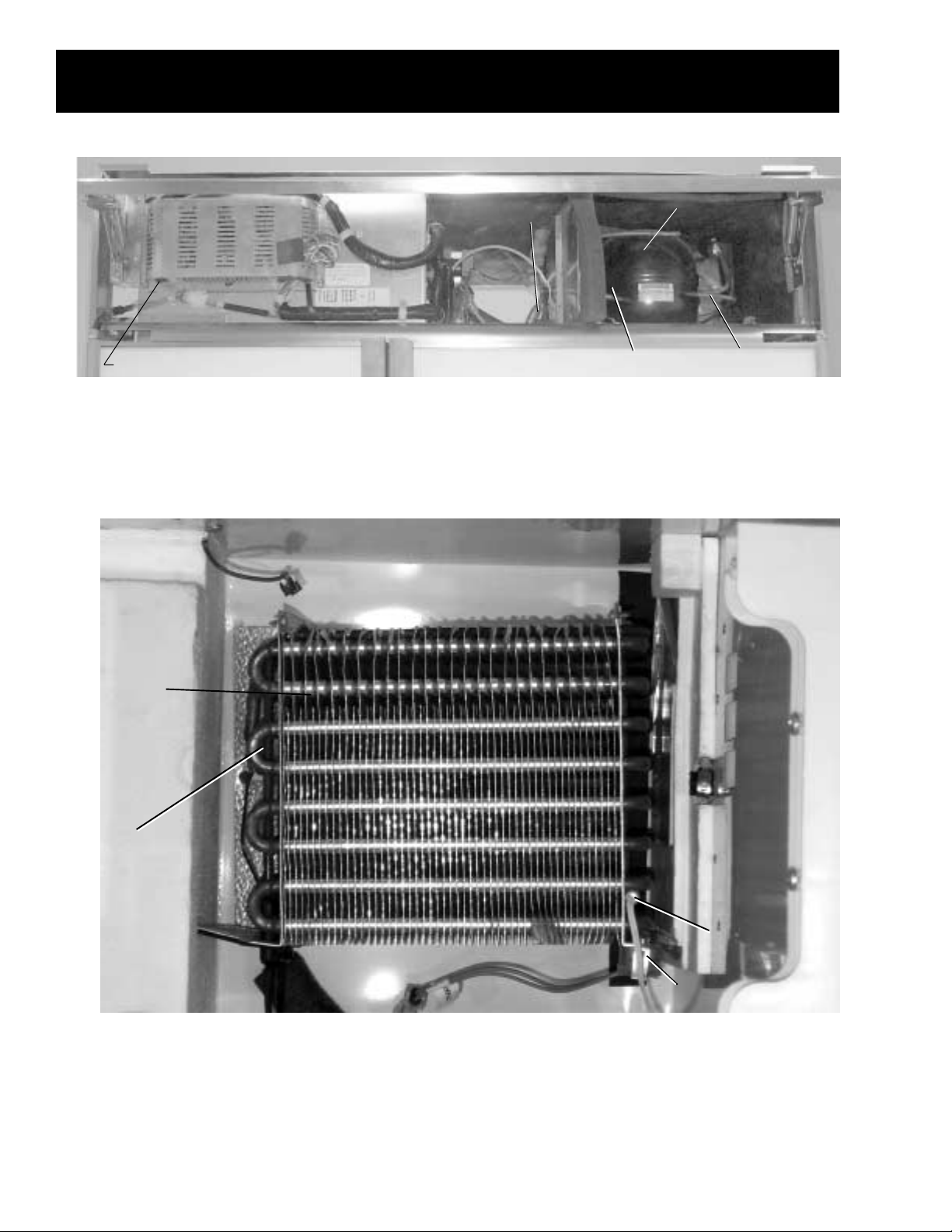
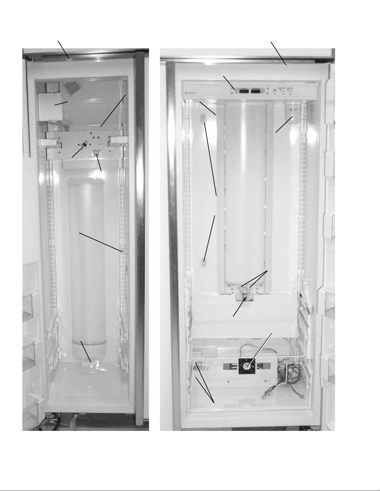
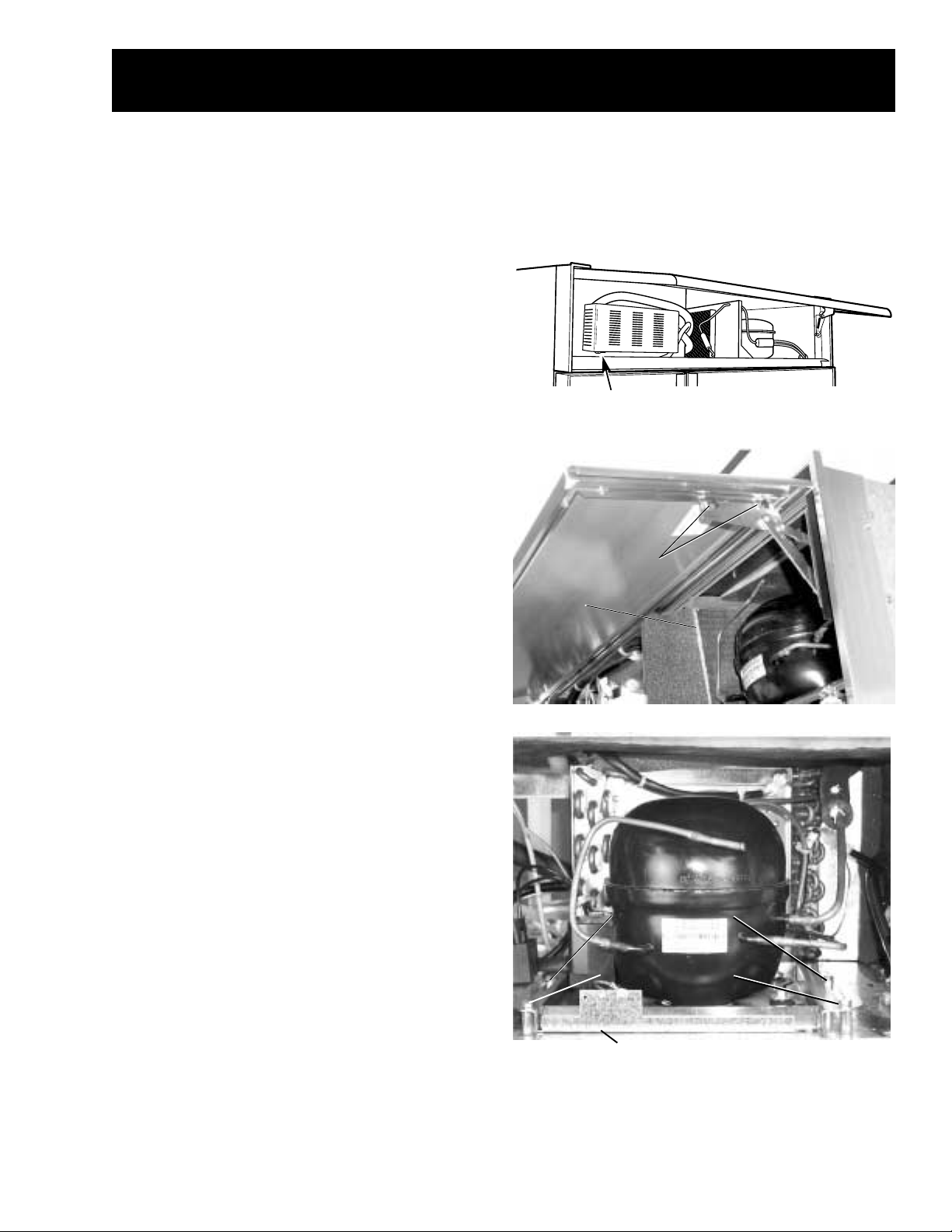
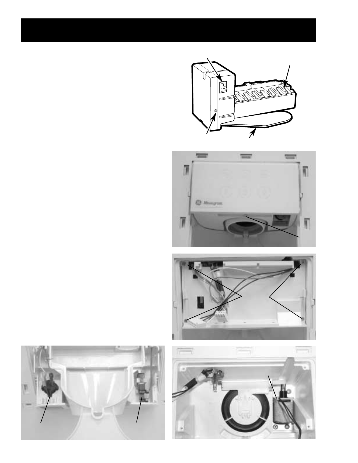
Component Locator Views
Figure 1 - Machine Compartment
Figure 2 - Evaporator (T op of Freezer)
Condenser Fan
Compressor
Dryer
Master Light Switch
(Sabbath Switch)
Overload &
PTCR Relay
Evaporator
Evaporator
Thermistor
Evaporator
Overtemperature
Thermodisc (TOD)
Defrost Heater
– 7 –
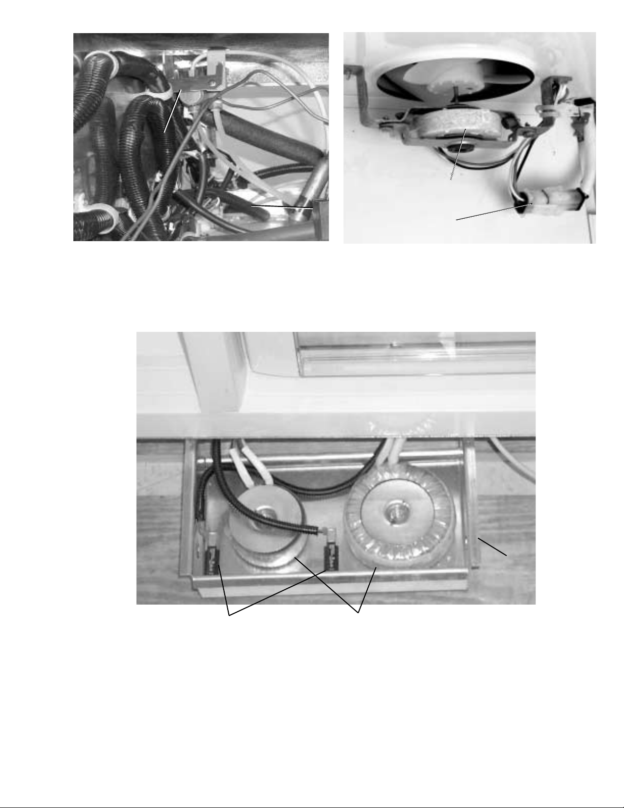
Figure 3 - Water V alve and Cap acitor
(Center of Machine Compartment)
Figure 4 - Evaporator Fan
Figure 5 - Light Circuit Transformers
Capacitor
Water Valve
Evaporator Fan Motor
Evaporator Fan
Connector
Circuit Breakers
Drawer Under
Center of Unit
Transformers
– 8 –
Climate Control
Drawer Fan
Figure 6 - Freezer Compartment
Figure 7 - Fresh Food Compartment
Freezer
Door Switch
Auger Drive
Airflow Grille
Icemaker
Cube Solenoid
Temperature
Overload Device
(TOD)
Freezer
Thermistor
Fresh Food
Door Switch
Temperature Touch Pad
Damper
Water Filter
Fresh Food
Thermistors
Climate Control
Drawer Dampers
Temperature
Overload Device
(TOD)
Lower
Fresh Food
Lights
– 9 –
The outer case is made of prepainted galvanized
steel. The fresh food and freezer liners are
painted metal with a smooth finish. The liners are
not removable or replaceable.
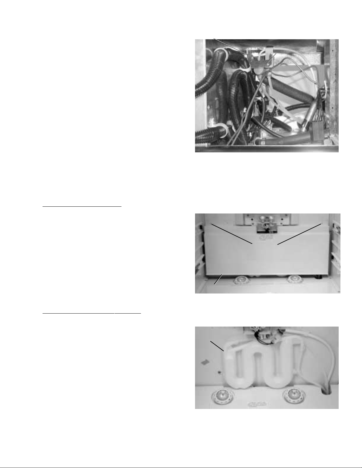
Machine Compartment
The machine compartment is located on the top of
the unit and has a movable chassis that can be
extended from the front of the unit to provide
access to the refrigeration system components.
Caution: Avoid kinking the refrigeration lines when
sliding the chassis out and back in.
To extend the chassis:
1. Remove the grille panel by removing 2 screws
from each side (see photo).
2. Remove the wire guard and rocker switch
panel.
3. Remove the condenser baffle.
4. Loosen 2 (7/16-in.) track bolts from the front of
the chassis track.
5. Remove 2 (7/16-in.) rear track bolts and the
spacers under the rear of the chassis track.
6. Pull the chassis forward until it reaches the
stops in the tracks, working the refrigeration
tubing as you pull the chassis out.
Note.
• When sliding the chassis back into position, be
certain the lines and wiring have not fallen
behind the chassis.
• Use the grille screws for adjustment when
realigning the grille.
Cabinet
The Master Light Switch (Sabbath switch) is
located behind the grille panel.
Machine Compartment
Chassis
Rear Track Bolt s
Rear T rack Bolts
Front Track Bolt s
Front Track Bolt s
2 Screws
Condenser
Baffle
– 10 –
Doors and Hinges
The doors are of one-piece construction with foam
insulation.
The inner door panel and outer door panel cannot
be separated and must be replaced as an
assembly.
Door Adjustment
Be sure the top hinge does not hit the cabinet trim.
Adjust the door up or down by turning the threaded
hinge pin on the bottom hinge of the fresh food
door.
The upper hinge on the freezer door is slotted to
allow the freezer door to be adjusted left or right.
Door Removal
WARNING: Use the appropriate safety equipment
and lifting techniques. Two persons may be
required for door removal.
Caution: Use wood or a heavy plastic sheet to
protect the floor where the door will be placed.
1. Remove all food and bins from the inner door
liner and tape door to cabinet.
2. Disconnect the spring from the pin and the
actuator arm.
3. Remove the Allen head bolt, bushing, and
spacer from the door and actuator arm.
4. If removing the freezer door, shut of f the water
supply , and disconnect the water line and
electrical connector.
5. Remove the upper hinge.
6. Lift door up and out to remove.
Lower Door Hinge
Note: If replacing lower door hinge, note the
placement of the door stop (pin).
1. Remove the door .
Note: Note the placement of spacers and washers
for reassembly.
2. Remove 3/8-in. hex screws (4) and hinge from
the underside of the cabinet.
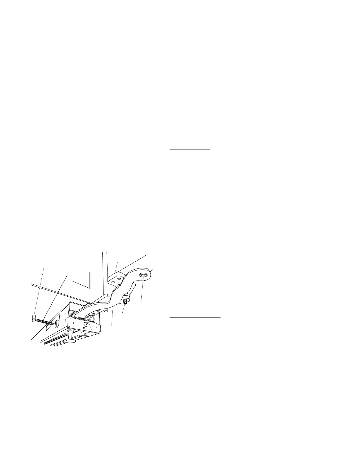
Door Closure Mechanism
The door closure mechanism uses a spring to
provide positive door closure from approximately
60 degrees. The door closure mechanism
actuator arm has a spring attached to the rear and
is supported by guide rollers on either side of the
base channel. The roller circumferences and the
actuator arm detents are matched for smooth
operation. The arm is attached to the door with an
Allen head shoulder bolt.
The closure mechanism allows easy opening to
approximately 90 degrees, where the arm has a
detent to permit the door to remain open at 90
degrees with minimal tension. Once the door is
opened beyond 90 degrees, the closure
mechanism pulls the door open until the closure
arm engages the door stop at approximately 130
degrees (factory setting, the door stop can be field
set to 90 degrees). The reverse action occurs
when the door is closed.
Note: The actuator arm is spring loaded with
moderate spring tension.
1. Disconnect the spring from the pin and the
actuator arm.
2. Remove the 3/16-in. Allen head bolt, bushing,
and spacer from the door and actuator arm.
GEA01267
Door
Hinge
Spring
Pin
3/16"
Allen
Head
Bolt
5/16"
Bolt
Actuator
Arm
Roller
Assembly
3. Remove 2 screws and the roller assembly
from the rail. Replace roller if excessively
worn.
– 11 –
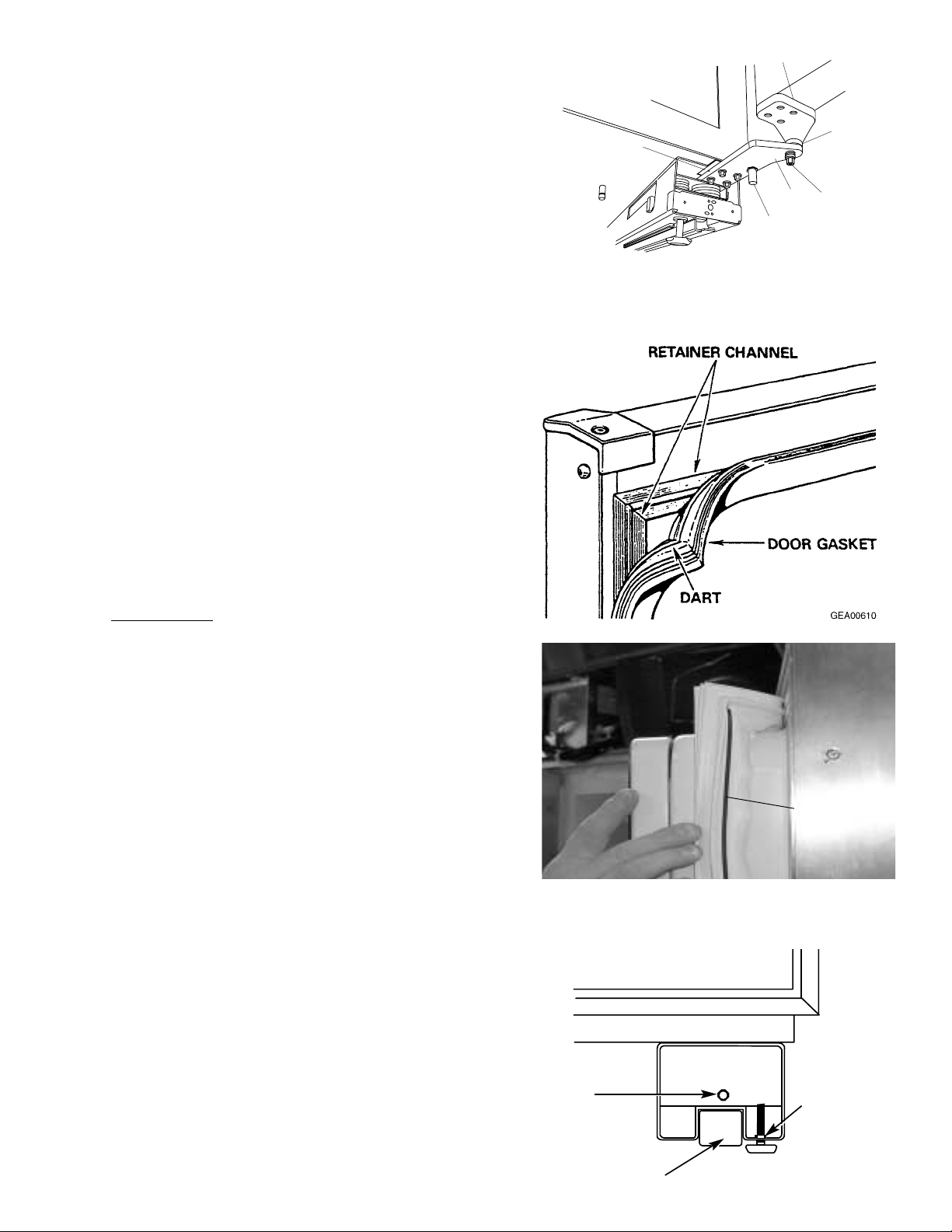
Door Gaskets
The fresh food and freezer doors have magnetic
gaskets that create a positive seal to the front of the
steel cabinet. The center mullion also has magnets to
assist in door sealing. Improper installation of the door
gasket will cause same-poled magnets to oppose one
another, preventing the door from closing tightly.
The magnetic door gaskets are secured to the doors
by a barbed edge that locks into a retainer channel.
The side of the gasket that is nearest the handle of the
door has a stripe on the inside of the barb (see photo).
Replacement
1. Starting at any corner, pull the old gasket out of the
retaining channel.
2. Soak the new gasket in warm water to make it
pliable.
3. Push the barbed edge of the gasket into the
retainer channel.
Hex Nut
Wheel
Leveling Leg
Stripe
(Handle Side
of Door)
GEA01268
Hinge
Door Stop
5/16"
Bolt
Hinge
Bushing
Base Channel Spacer
3. Remove T-27 Torx screws (4) and hinge from the
bottom of the door .
Rollers and Leveling
This model has 4-point leveling provided by adjustable
rollers on the rear and leveling legs on the front. It also
has 2 nonadjustable front rollers that are used only for
unit positioning.
T o level the unit:
1. Turn the 7/16-in. hex nut, located above the front
rollers, to adjust the roller on the rear of the unit.
Turn clockwise to raise, counterclockwise to lower.
2. Turn the front legs with a 1-1/4
in. open end
wrench to adjust the front of the unit. T urn
clockwise to raise, counterclockwise to lower.
– 12 –
The icemaker is mounted to the upper left wall of
the freezer cabinet. Under normal operating
conditions, temperatures, door openings, and food
load, the icemaker is capable of producing
approximately 100 to 130 cubes in a 24-hour
period.
To service the icemaker, refer to GE Publication
31-9063.
Controls
The electronic controls on the dispenser are
interactive. The control panel is equipped with a
proximity sensor that causes the panel to light up
as you approach the dispenser (approx. 2 inches).
Removal
1. Remove the bezel from the outside of the
freezer door.
Note: On stainless steel models, the front panel
must be removed. Remove screws from top,
bottom, and hinge side. Pull out on hinge side.
2. Remove the screw from the bottom of the
control panel. Lift up and pull the bottom of the
panel out. Disconnect the connectors, and
remove the control panel.
3. Remove 4 screws and the backing panel.
4. From the back side of the panel, remove the
water switch and the light socket.
5. Remove 3 screws and the duct door solenoid.
Icemaker
Feeler Arm
Power Switch
Green
Power Light
Ice and W ater Dispenser
Screw
4 Screws
Duct Door
Solenoid
Light Socket
Water Switch
– 13 –
Water V alve and Water Tank
The water valve is mounted in the left side of the
machine compartment.
A plastic water line is routed from under the unit,
up the back of the cabinet, into the machine
compartment, and to the water filter . A line then
goes from the water filter to the water valve.
Two low-pressure plastic water lines supply water
to the icemaker and door dispenser from the water
valve. A plastic water line is routed from the water
valve, out the back of the machine compartment,
down the back of the cabinet through the bottom of
the unit, and into the fresh food compartment
where it is attached to the cold water tank. A line is
routed from the cold water tank through the bottom
of the unit into the freezer door to supply the water
dispenser. The icemaker water line is routed from
the water valve through the machine compartment
to the icemaker. The icemaker fill tube is also
plastic.
To Replace the Water V alve
Note: Some water may leak from the water supply
line and valve when they are disconnected.
1. Shut off the water supply to the unit.
2. Open the grille panel.
3. Remove 1 Phillips screw attaching the water
valve to the filter bracket.
4. Disconnect the wiring harness connector and
3 water lines from the water valve and remove.
To Replace the Chilled Water Tank
Note: Some water may leak from the water supply
line and valve when they are disconnected.
1. Shut off the water supply to the unit.
2. Remove 2 screws and the chilled water tank
cover inside the fresh food compartment.
3. Remove 2 screws from the chilled water tank.
4. Cut the water lines leaving enough line to
reconnect. Use union WR02X10471
(5/16 x 5/16).
Water Valve
Screw
Screw
Chilled Water Tank
Water Tank Cover
Screws
– 14 –
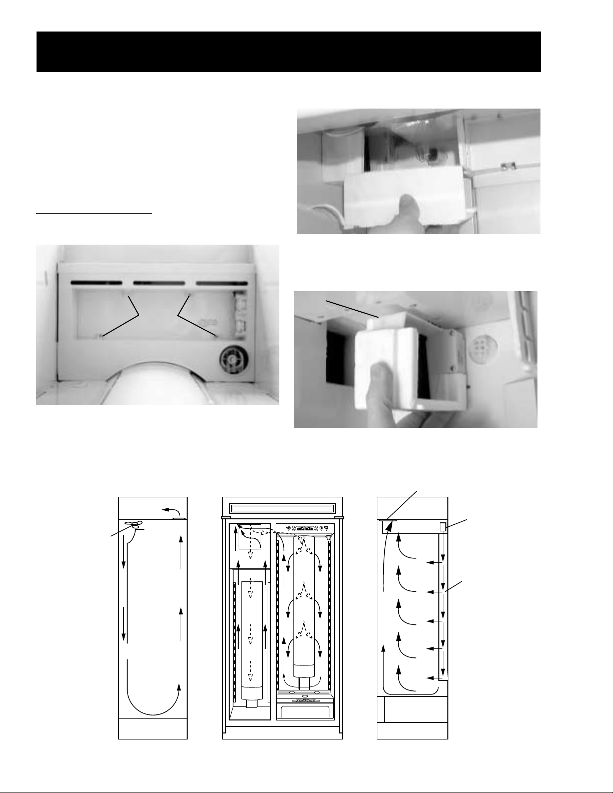
Damper
The fresh food compartment receives chilled air
via an electronic damper that is positioned at the
top rear of the fresh food compartment. The
damper is controlled by the main control board and
when open, allows the evaporator fan to push
chilled air from the evaporator into the fresh food
compartment.
To Remove the Damper
1. Remove the light cover .
Airflow
3. Remove the Styrofoam section covering the
damper.
4. Disconnect the damper wiring connector.
5. Carefully pull the damper out of the mullion and
remove.
2. Remove 4 Phillips screws and the light
assembly.
GEA01269
Top
BottomFreezer Side Fresh Food Side
Return
Evaporator
Front FrontBack Back
Damper
Air
Tower
Evap.
Fan
Damper
Screws
– 15 –
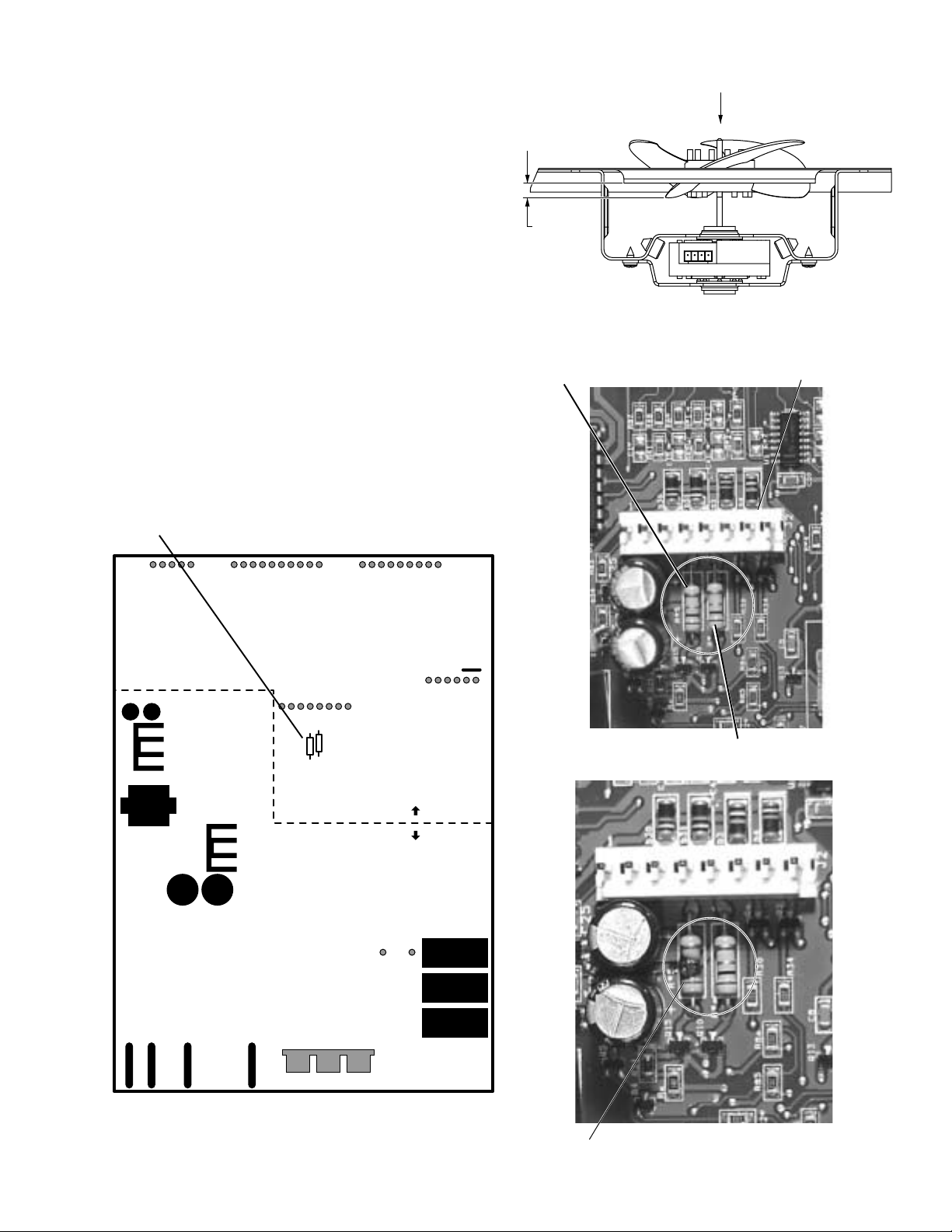
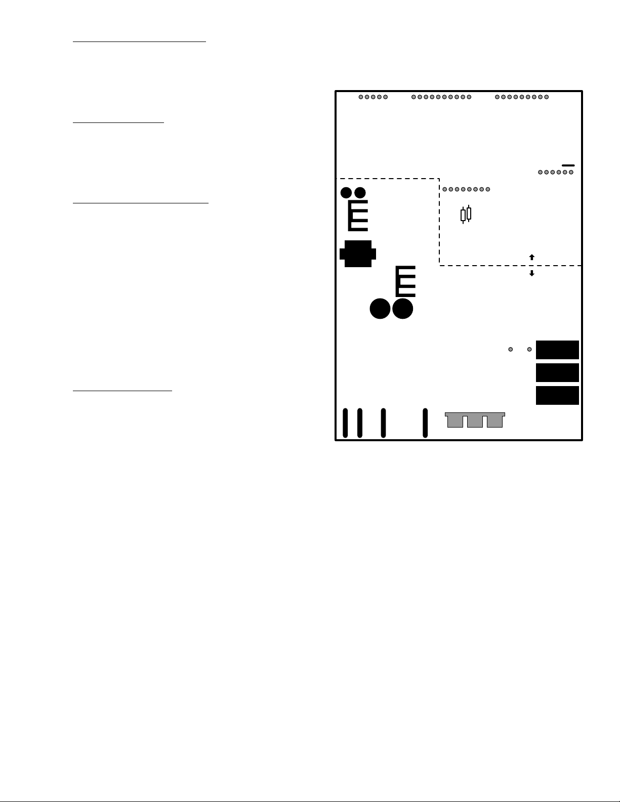
Bad Evaporator Fan Resistor
J2 Connector
GEA01140
Evaporator Fan Resistor
Condenser Fan Resistor
Evaporator and Condenser Fan Resistors
Evaporator Fan Adjustment
Evaporator Fan
The position of the fan blade in relation to the
shroud is critical. Refer to evaporator fan
adjustment graphic for specifications.
If the fan shorts, it may damage the main control
board. If the resistor on the main control board is
burnt, you must replace the fan and the board (see
photo).
The evaporator fan utilizes a permanent magnet,
4-pole, DC motor that can operate at three
different speeds: high, medium, and low (medium
and low are the same speed, controlled by the
main control board). The speed of the fan is
controlled by the voltage output from the main
control board. V oltage output from the control
board to the fan is 12.6 VDC; however, in order to
regulate the speed of the fan, the control board
uses Pulse Width Modulation (PWM) during low-
5/16 +/- .03
GEA01196
Pin 1 J8
Compressor
Pin 1 J9
Defrost Heater
Pin 1 J11
Line
Evaporator Fan Tach.
J2 Pin 1
Personality Input 5
Pin 2
Fan Common
Pin 3
Evaporator Fan
Pin 4
Condenser Fan
Pin 5
FF Fan
Pin 6
QuickChill Damper1 +
J5 Pin 1
QuickChill Damper1 -
Pin 2
QuickChill Damper2 +
Pin 3
QuickChill Damper2 -
Pin 4
+5V
Pin 5
QuickChill Thermistor
Pin 6
QuickChill Fan
Pin 7
Fan +12V
Pin 8
FF1 Thermistor
J1 Pin 1
FF2 Thermistor
Pin 2
FZ Thermistor
Pin 3
Evaporator Thermistor
Pin 4
+5V
Pin 5
Personality Input 1
Pin 6
Personality Input 2
Pin 7
Personality Input 3
Pin 8
Personality Input 4
Pin 9
Damper - Blue
J3 Pin 1
Damper - White
Pin 2
Damper - Red
Pin 3
Damper - Yellow
Pin 4
FF Encoder Select
Pin 5
Comm. Tx/Rx
J4 Pin 1
Comm. +12V
Pin 2
Comm. Common
Pin 3
Discrete Disp. Input 1
Pin 4
Discrete Disp. Input 2
Pin 5
FZ Encoder Select
Pin 6
Encoder Signal
Pin 7
Encoder Signal
Pin 8
Encoder Signal
Pin 9
Encoder Signal
Pin 10
Pin 1 J12
Monogram Drain Pan Heater
Pin 9 J7
Neutral
Pin 8
NIC
Pin 7
FZ Door Switch
Pin 6
FF Door Switch
Pin 5
QuickChill Heater
Pin 4
Auger Motor Interlock
Pin 3
Water Valve
Pin 2
Crusher Solenoid
Pin 1
Auger Motor
Pin 1
QuickChill Htr.
Pin 2
QuickChill Htr.
Low Voltage DC
120 VA C
Airflow
5/16
+/- 0.03

– 16 –
speed and medium-speed operation. When operating in low and medium speeds, voltage is sent in
pulses (much like a duty cycle) as opposed to an uninterrupted flow. This pulsing of 12.6 VDC produces
effective voltage being received at the motor , which is the equivalent to a reduction in voltage. Fan speed
will be selected and maintained by the control board regulating the length and frequency of the 12.6 VDC
pulse.
One complete revolution of the motor is comprised of all 4 poles. To determine the rpm of the fan:
Measure the frequency being applied to the motor . Multiply this number by 15 (60 seconds divided by 4
poles). For example, a frequency measurement of 200 Hz multiplied by 15 would show a fan speed of
3000 rpm (15 x 200 = 3000). Temperature may cause some fan speed variation. Fan speed may vary
+/- 5%, depending on the temperature, with higher temperatures causing slightly higher speeds.
The evaporator fan motor uses a 4-wire connection, utilizing a common wire (white), feedback/rpm
wire (blue), supply wire (red), and a signal wire (yellow).
High Speed (12 VDC measured)
Medium Speed (8 VDC measured)
Low Speed (4 VDC measured)
EVAPORATOR FAN SPEEDS
12 VDC
8 VDC
4 VDC
12 VDC
0 VDC
0 VDC
0 VDC
12VDC
12 VDC
GEA01139
High S peed (12 VDC measured)
Medium and Low S peed (8 VDC measured)
– 17 –
White Wire (DC Common)
The white wire is the DC common wire used for
testing. During repairs, DC polarity must be
observed. Reversing the DC polarity will cause a
shorted motor and/or board.
Red Wire (Supply)
Each motor uses an internal electronic controller
to operate the motor. Supply volt age from the
main control board remains at a constant
12 VDC.
Blue Wire (Feedback/RPM)
The blue wire feeds rpm (speed) information to
the main control board, allowing the board to
maintain consistent fan speeds. Loss of feedback
from the blue wire will result in the fan accelerating
to maximum speed. Measure the fan rpm using
the frequency between the blue and white wires.
High speed - 195 to 200 Hz
Medium speed - 145 to 160 Hz
Note: Fan operates at the same speed in low and
medium.
Low speed - 145 to 160 Hz (same as medium)
Yellow Wire (Signal)
The yellow wire is the input wire from the main
control board. The main control board provides
8.1 VDC effective voltage for low speed, 8.1 VDC
effective voltage for medium speed, and 12.6 VDC
for high speed. The fan will operate in low speed
only when the fresh food thermistor is satisfied.
Note: When testing these motors:
• You cannot test with an ohmmeter.
• DC common is not AC common.
• Verify 2 volt age potentials:
a. Red to white - power for internal controller.
b. Yellow to white - power for fan.
• Observe circuit polarity.
• Motors can be run for short periods using a
9-volt battery . Connect the white wire to the
negative (-) battery terminal only. Connect the
red and yellow wires to the positive (+) battery
terminal.
GEA01196
Pin 1 J8
Compressor
Pin 1 J9
Defrost Heater
Pin 1 J11
Line
Evaporator Fan Tach.
J2 Pin 1
Personality Input 5
Pin 2
Fan Common
Pin 3
Evaporator Fan
Pin 4
Condenser Fan
Pin 5
FF Fan
Pin 6
QuickChill Damper1 +
J5 Pin 1
QuickChill Damper1 -
Pin 2
QuickChill Damper2 +
Pin 3
QuickChill Damper2 -
Pin 4
+5V
Pin 5
QuickChill Thermistor
Pin 6
QuickChill Fan
Pin 7
Fan +12V
Pin 8
FF1 Thermistor
J1 Pin 1
FF2 Thermistor
Pin 2
FZ Thermistor
Pin 3
Evaporator Thermistor
Pin 4
+5V
Pin 5
Personality Input 1
Pin 6
Personality Input 2
Pin 7
Personality Input 3
Pin 8
Personality Input 4
Pin 9
Damper - Blue
J3 Pin 1
Damper - White
Pin 2
Damper - Red
Pin 3
Damper - Yellow
Pin 4
FF Encoder Select
Pin 5
Comm. Tx/Rx
J4 Pin 1
Comm. +12V
Pin 2
Comm. Common
Pin 3
Discrete Disp. Input 1
Pin 4
Discrete Disp. Input 2
Pin 5
FZ Encoder Select
Pin 6
Encoder Signal
Pin 7
Encoder Signal
Pin 8
Encoder Signal
Pin 9
Encoder Signal
Pin 10
Pin 1 J12
Monogram Drain Pan Heater
Pin 9 J7
Neutral
Pin 8
NIC
Pin 7
FZ Door Switch
Pin 6
FF Door Switch
Pin 5
QuickChill Heater
Pin 4
Auger Motor Interlock
Pin 3
Water Valve
Pin 2
Crusher Solenoid
Pin 1
Auger Motor
Pin 1
QuickChill Htr.
Pin 2
QuickChill Htr.
Low Voltage DC
120 VA C
– 18 –
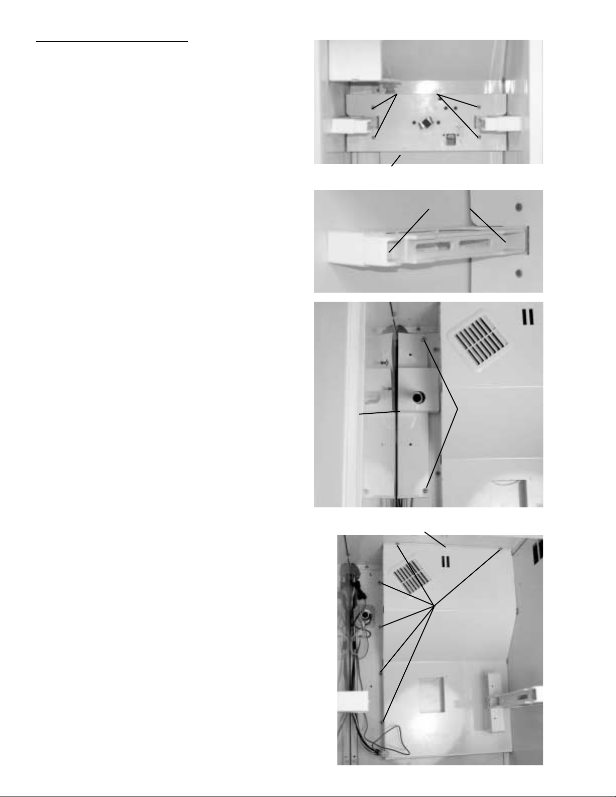
To Remove the Evaporator Fan
1. Remove the ice bucket.
2. Disconnect the icemaker connector. Loosen 2
screws and remove icemaker.
3. Remove 4 screws and slide the icemaker drive
motor assembly forward. Disconnect the wiring
connector and remove the assembly.
4. Remove 2 screws and inner section of left ice
bucket track.
5. Remove 2 screws and wiring cover.
6. Remove 6 screws and evaporator fan cover.
Screws
Icemaker Drive
Motor Assembly
Screws
Screws
Wiring
Cover
Screws
Evaporator Fan Cover
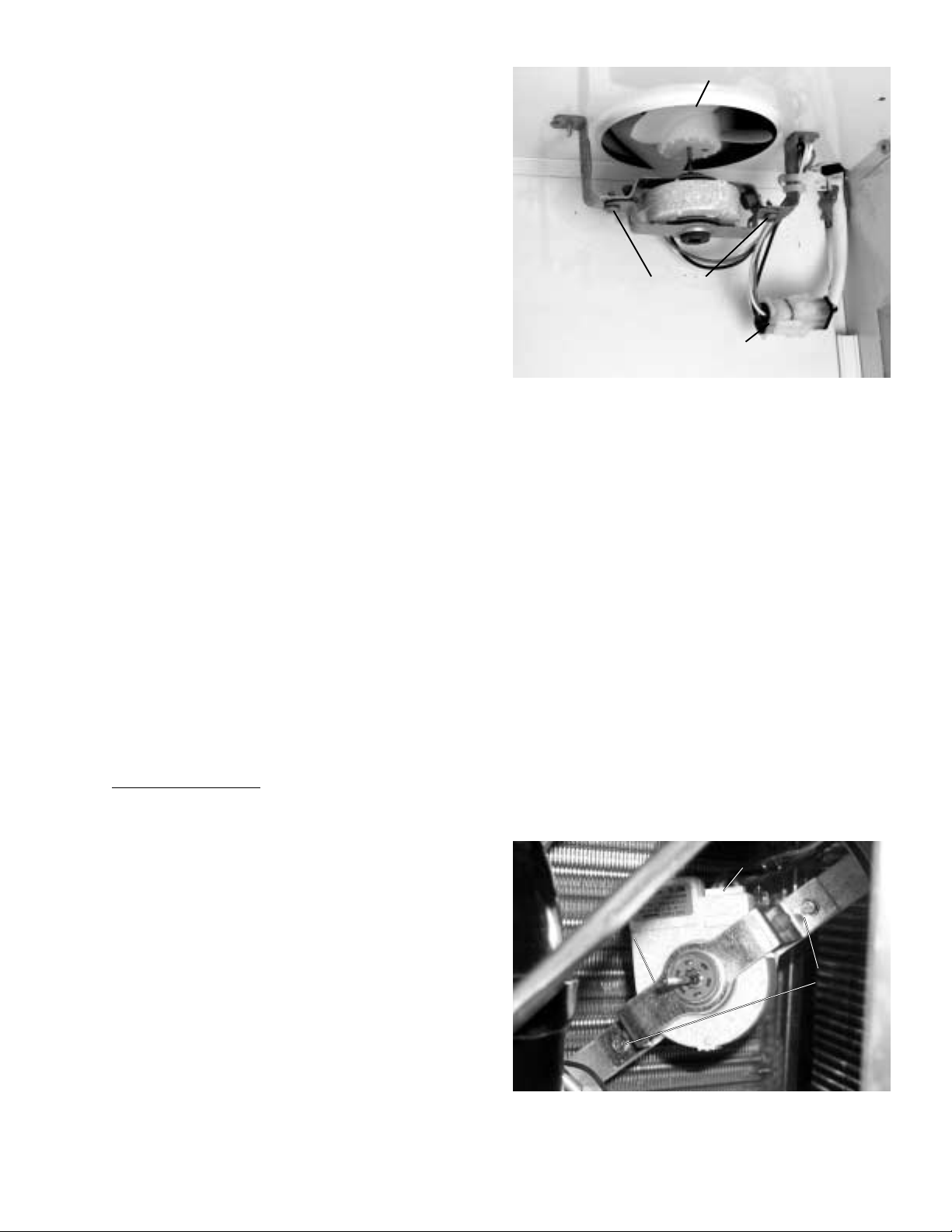
– 19 –
7. Disconnect the evaporator fan wiring
connector.
8. Remove 2 screws from the fan mounting
bracket and remove the fan.
Condenser Fan
The condenser fan utilizes a DC motor that
operates at a single speed and is mounted in the
machine compartment. When the fan is
operating, air is pulled through the condenser ,
drawing air through the coils. The air is then
exhausted past the compressor and out the front
of the refrigerator on the right side.
Inlet air is available through the left front and left
rear of the machine compartment.
If the fan shorts, it will damage the main control
board. If the resistor on the main control board is
burnt, you must replace the fan and the board (see
photo page 15).
The condenser fan is mounted with screws to a
fan shroud and mounting bracket in back of the
condenser.
To Remove the Fan
1. Extend the chassis (see Machine
Compartment in the Cabinet chapter).
2. Pull the blade off the motor shaft.
3. Cut the wire tie securing the fan wiring to the
fan bracket.
Caution: Fan connector can be separated into 3
segments (center, left side, and right side).
Disconnect the fan connector at the center only.
4. Disconnect the fan connector.
5. Feed wiring through the hole in the fan shroud.
6. Remove 2 screws, top section of fan bracket,
and motor.
Condenser Fan Motor
Screws
Fan Bracket
Fan Bracket
Screws
Wire Connector
Evaporator Fan

– 20 –
Adaptive Defrost
Adaptive Defrost can be described as a defrost
system that adapts to a refrigerator’s surrounding
environment and household usage.
Unlike conventional defrost systems that use
electromechanical timers with a fixed defrost cycle
time, Adaptive Defrost utilizes an intelligent,
electronic control to determine when the defrost
cycle is necessary. In order to accomplish the
correct defrost cycle time, the main control board
monitors the following refrigerator operations:
• Length of time the refrigerator doors were open
since the last defrost cycle
• Length of time the compressor has run since
the last defrost cycle
• Amount of time the defrost heaters were on in
the last defrost cycle
Adaptive Defrost is divided into 4 separate cycles.
Those operations are:
• Cooling Operation
• Pre-Chill Operation
• Defrost Heater Operation
• Dwell Period
(See Pub. #31-9062 for more information on
Adaptive Defrost.)
Adaptive Defrost (Cooling Operation)
During the cooling operation, the main control
board monitors door opening (fresh food door and
freezer drawer) and compressor run times. The
board counts the time the doors are open. It
reduces the length of time between defrosts by
300 seconds (multiplication factor) for each
second that each door is open (if both doors are
open, it reduces it by twice the amount). The
multiplication factor reduces compressor run time.
If the doors are not opened, the compressor will
run up to 60 hours between defrosts. If the doors
are opened frequently and/or for long periods of
time, the compressor run time between defrosts
will be reduced to as little as 8 hours.
Adaptive Defrost (Pre-Chill Operation)
When the main control board determines that
defrost is necessary, it will force the refrigerator
into a continuous cool mode (pre-chill). During pre-
chill, the freezer temperature may be driven below
the set point. However, the fresh food temperature
will be regulated by the evaporator fan running at
low speed. Pre-chill will last for 30 minutes. These
models do have an 8-hour defrost holdoff.
Adaptive Defrost (Defrost Heater Operation)
After 30 minutes of pre-chill operation, the main
control board turns off the compressor, condenser
fan, and evaporator fan.
During defrost operation, the main control board
monitors the evaporator temperature using
evaporator thermistor inputs. T ypically, the
evaporator thermistor will sense a temperature of
38 °F within 16 minutes. When the thermistor
senses 38 °F, the main control board will terminate
defrost heater operation. Maximum defrost cycle
(heater on) time is 35 minutes (main control board
time out).
The defrost system is protected by a defrost
overtemperature thermodisc (bimetal switch). The
thermostat opens when the evaporator
temperature raises to 60 °F and closes when the
evaporator temperature lowers to 45 °F.
Adaptive Defrost (Dwell Period)
After defrost heater operation has been terminated
by the main control board, a 20-minute dwell
period occurs. During this period, the
compressor, condenser fan, and evaporator fan
remain off. The remaining frost melting from the
evaporator will continue to drip and drain so that,
prior to the cooling operation, the evaporator will be
totally clear of any moisture. The pan heater is on
for the entire 20 minute dwell period.
Defrost System
 Loading...