


GE Consumer Home Services Training
TECHNICAL SERVICE GUIDE
Advantium™ Built-In Oven
TM
MODEL SERIES:
SCB2000
SCB2001
ZSC2000
ZSC2001
PUB # 31-9057 08/00

!
IMPORTANT SAFETY NOTICE
The information in this service guide is intended for use by individuals possessing adequate backgrounds of electrical, electronic, and mechanical experience. Any attempt to repair a major appliance may result in personal injury and property damage. The manufacturer or seller cannot be responsible for the interpretation of this information, nor can it assume any liability in connection with its use.
WARNING
To avoid personal injury, disconnect power before servicing this product. If grounding wires, screws, straps, clips, nuts, or washers used to complete a path to ground are removed for service, they must be returned to their original position and properly fastened.
GE Consumer Home Services Training
Technical Service Guide
Copyright © 2000
All rights reserved. This service guide may not be reproduced in whole or in part in any form without written permission from the General Electric Company.
Table of Contents
Welcome to Advantium . . . . . . . . . . . . . . . . . . . . . . . . . . . . . . . . . . . . . . . . . . . . 2
Installation Instructions . . . . . . . . . . . . . . . . . . . . . . . . . . . . . . . . . . . . . . . . . . . 4
Specifications . . . . . . . . . . . . . . . . . . . . . . . . . . . . . . . . . . . . . . . . . . . . . . . . . . 10
Warranty Information . . . . . . . . . . . . . . . . . . . . . . . . . . . . . . . . . . . . . . . . . . . . . 11
Overview of Advantium . . . . . . . . . . . . . . . . . . . . . . . . . . . . . . . . . . . . . . . . . . 12
Control Panel Features . . . . . . . . . . . . . . . . . . . . . . . . . . . . . . . . . . . . . . . . . . 13
How to Speedcook . . . . . . . . . . . . . . . . . . . . . . . . . . . . . . . . . . . . . . . . . . . . . . 15
Operating Characteristics . . . . . . . . . . . . . . . . . . . . . . . . . . . . . . . . . . . . . . . . 16
Mechanical Disassembly . . . . . . . . . . . . . . . . . . . . . . . . . . . . . . . . . . . . . . . . . 26
Troubleshooting . . . . . . . . . . . . . . . . . . . . . . . . . . . . . . . . . . . . . . . . . . . . . . . . 41
Schematics and Wiring Diagrams . . . . . . . . . . . . . . . . . . . . . . . . . . . . . . . . . . 48
Illustrated Parts Breakdown . . . . . . . . . . . . . . . . . . . . . . . . . . . . . . . . . . . . . . 54
GEA00403
– 1 –

Welcome to 


 TM
TM
The new Advantium™ oven uses breakthrough speedcook technology to cook food with light. Foods cook in a fraction of the time needed in conventional ovens, with delicious results. Advantium browns, bakes, roasts, broils, and crisps just like a conventional oven, and requires no preheating. Advantium uses high-intensity halogen lights to cook food from the top and bottom simultaneously, cooking the surface and interior to seal in moisture and flavor. For added convenience, the Advantium oven can be converted to a fully functional microwave by simply pressing a button.
the cookbook for proper cookware selection and food placement on the turntable surface.
Pub. No. 49-40070
Advantium™ Owner’s Kit
Included with the purchase of the Advantium™ oven is an Advantium™ Owner’s Kit. The kit includes the following helpful tools and literature:
•136-page cookbook
•4-page cooking guide
•Owner’s Manual (use & care guide)
•“Getting Started” video (17:37 min.)
•Cleaning scraper
Cooking Guide
The cooking guide is a four-page, quick-reference guide containing numerous helpful cooking tips. In addition, it contains helpful use and care information and two pages of information which will assist the consumer in adapting their favorite recipe for the Advantium oven.
Pub. No. 49-40122
Pub. No. 28-X139
“Getting Started” Video (17:37 min.)
Cookbook
The cookbook includes numerous recipes, helpful cooking tips, information on proper cooking techniques, and proper use of cookware for various types of recipes. The cookbook is also a helpful diagnostic tool when servicing an Advantium™ oven for a cooking issue. Be sure to reference the cookbook prior to servicing a unit for any cooking concern. Be sure that the customer is following the proper selections for the type and size of food. Also be sure to consult the front of
The “Getting Started” video provides general information on proper use and care, and is intended to help the consumer during their initial use of the product (getting started).
Pub. No. 28-X060
– 2 –

Owner’s Manual
The Owner’s Manual provides the customer with detailed information on the operation, use, and care of their product. It also contains a section on helpful troubleshooting tips.
|
|
|
|
GE Appliances |
|
||
Oven |
Advantium |
|
|
Other Features |
|
|
|
Advantium Quick Start . . . . . . |
. . . |
.10 |
Automatic fan . . . . . . . |
. . . . . . . .34 |
SCB2000 |
|
|
. . . . . . . . . . . .Cooking controls |
. . |
.13 |
. . . . . . . .Beeper volume |
. . . . . . .32 |
SCB2001 |
|
|
Customer information . . . . . . . . |
. . |
. .8 |
Child lockout . . . . . . . . . |
. . . . . . .34 |
|
||
Oven features . . . . . . . . . . . . . . |
. . |
.12 |
Clock . . . . . . . . . . . . . . . |
. . . .10, 32 |
|
|
|
What is Advantium? . . . . . . . . . |
. . |
. .9 |
Display ON/OFF . . . . . . |
. . . . . . .32 |
|
|
|
Safety . . . . . . . . . . . . . . . . . . . . |
. . |
2— 7 |
Help . . . . . . . . . . . . . . . |
. . . . . . .33 |
|
|
|
Speedcooking |
|
|
Review . . . . . . . . . . . . . |
. . . . . . .32 |
|
|
|
|
|
Scroll speed . . . . . . . . . . |
. . . . . . .32 |
|
|
||
Cooking tips . . . . . . . . . . . . . . . |
. . |
.15 |
Timer . . . . . . . . . . . . . . |
. . . . . . .34 |
|
|
|
Custom speedcook recipes . . . |
18— 19 |
|
|
|
|
||
Custom speedcook recipe log . |
. . |
.20 |
Care and Cleaning |
|
|
|
|
Manual speedcook . . . . . . . . . . |
. . |
.17 |
Cleaning the inside . . . . . |
. . . .35— 36 |
|
|
|
Power level . . . . . . . . . . . . . . . . |
. . |
.16 |
Cleaning the outside . . . . . |
. . . . . . .37 |
|
|
|
Repeat last . . . . . . . . . . . . . . . . |
. . |
.15 |
Lamp covers . . . . . . . . . . . |
. . . . . . .36 |
|
|
|
Resume feature . . . . . . . . . . . . |
. . |
.15 |
|
|
|
|
|
Speedcook cookware . . . . . . . . |
. . |
.17 |
Troubleshooting |
|
|
|
|
Advantium“ |
. . . . . .Speedcook menu guide |
. . |
.11 |
Problem Solver . . . . . . . . . |
. . . .38, 39 |
|
|
Speedcook-safe cookware. . . . . |
. . |
. .5 |
|
|
|
|
|
Things that are normal . . . . . . . |
. . |
.21 |
Customer Service |
|
|
Pub. No. 49-40101 |
|
Using a pre-set speedcook menu . |
14. |
|
|
||||
|
Microwaving |
|
|
Customer information . . . . |
. . . . . . . .8 |
|
|
|
Cooking tips . . . . . . . . . . . . . . . |
. . |
.23 |
Product Registration . . . . . |
. . . .41, 42 |
|
|
|
Custom microwave recipes . . . |
24— 25 |
Service phone numbers . . |
Back Cover |
|
||
|
Custom microwave recipe log . |
. . |
.24 |
Warranty . . . . . . . . . . . . . . |
. . . . . . .43 |
|
|
|
Defrost (auto) . . . . . . . . . . . . . . |
. . |
.26 |
|
|
|
|
|
Defrost (time) . . . . . . . . . . . . . . |
. . |
.26 |
|
|
|
|
|
Defrosting tips . . . . . . . . . . . . . . |
. . |
.27 |
|
|
|
|
|
Micro Express . . . . . . . . . . . . . . |
11, 23 |
|
|
|
|
|
|
Microwave power levels . . . . . . |
. . |
.23 |
|
|
|
|
|
Microwave-safe cookware . . . . |
. . |
. .6 |
|
|
|
|
|
Precautions to avoid possible |
|
|
|
|
|
|
|
exposure to excessive |
|
|
|
|
|
|
|
microwave energy . . . . . . . . . . |
. . |
. .2 |
|
|
|
|
|
Sensor cooking . . . . . . . . . . . . |
28— 29 |
|
|
|
|
|
|
Things that are normal . . . . . . . |
. . |
.30 |
|
|
|
|
|
Time cook . . . . . . . . . . . . . . . . . |
. . |
.23 |
|
|
|
|
|
Using pre-set |
|
|
|
|
|
|
|
microwave selections . . . . . . . . |
. . |
.22 |
|
|
|
|
http://geadvantium.com |
|
|
|
|
|
|
|
|
|
|
|
Part No. 164D3370P099 |
Pub. No. 49-40101 |
3-00 JR |
|
Scraper/Cleaner
The last item included in the Advantium™ Owner’s Kit is a scraper/cleaner. This tool is included in order to aid the consumer in cleaning the upper and lower halogen lamp covers. These covers must be kept clean in order to ensure maximum cooking efficiency.
WX5X1614
GEA00410
For heavy or burned on soil
GEA00411
– 3 –

Installation Instructions
Before you begin — Read these instructions completely and carefully.
•Save these instructions for local inspector’s use.
•Observe all governing codes and ordinances. Note to Installer: Be sure to leave these instructions with the consumer.
Note to Consumer: Keep these instructions with your Owner’s Manual for future reference.
WARNING: This appliance must be properly grounded. See “Electrical Requirements” in this section.
Proper installation is the responsibility of the installer. Product failure due to improper installation is not covered under the GE Appliance Warranty. See the Owner’s Manual for warranty information.
Use this appliance only for its intended purpose.
Caution: This oven should be installed by a qualified installer or service technician.
• Never use the oven for warming or heating a room. Prolonged use of the oven without adequate ventilation can be hazardous.
Check with local utilities for electrical codes that apply in your area. Local codes vary. Installation of electrical connections and grounding must comply with applicable codes. In the absence of local codes, the oven should be installed in accordance with National Electrical Code ANSI/NFPA 70 or latest edition.
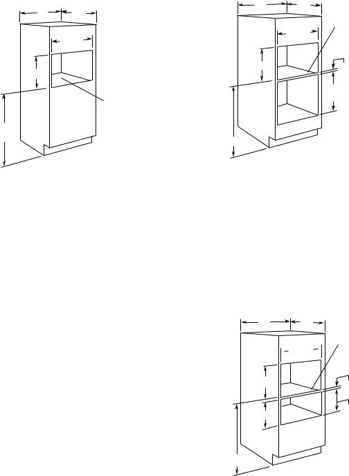
Product Dimensions
|
15" |
14-1/8" |
27/32" |
|
|
(Recessed |
|
||
28-7/16" |
Portion) |
|
|
|
|
|
|
|
9/16" |
|
|
20-27/32" |
|
|
|
21-7/8" |
|
|
27/32" |
|
|
|
|
|
|
|
|
|
13" |
15-27/32" |
29-25/32" |
7/8" |
15/32" |
11/16" |
|
||||
|
GEA00354 |
|||
GEA00355
Advance Planning
•This oven may be installed directly into a wall or wall oven cabinetry, 30 in. minimum width.
•The front surface of the oven will be nearly flush with surrounding cabinetry doors.
•This oven can be installed over any GE single electric built-in oven or a single GE electric built-in warming drawer.
•This oven must be installed at least 36 in. above the floor.
WARNING: For personal safety, this oven cannot be installed in a cabinet arrangement such as an island or peninsula.
Caution: This oven is not approved for use above another built-in speedcook oven, side-by-side, or under-the-countertop installations.
•Cabinets installed adjacent to wall ovens must have an adhesion specification of at least 194°F temperature rating.
•Allow for clearance to adjacent corners, walls, drawers, etc.
Tools and Materials Required
•2 x 4 or 2 x 2 lumber for runners
•Saw
•Level
•Drill and 3/32-in. bit
•Phillips screwdriver
•Wood screws and adhesive or other hardware for installing runners or shelf to support oven
Electrical Requirements
•Junction box
•Electrical cable - 3-conductor or 4-conductor wire, as required by local codes
•UL-listed conduit connector
•Wire cutters and wire stripper
– 4 –
Prepare the Opening
Single Speedcook Installation
30" |
19" |
|
Min |
||
|
28-1/2" |
|
21" |
|
|
|
Construct Solid |
|
|
Bottom Min. 3/8" |
|
|
Plywood |
|
|
Supported by |
|
|
2 x 4 or 1 x 2 |
|
36-3/4" Min. |
Runners, all |
|
Four Sides |
||
Required |
||
|
||
|
GEA00356 |
Speedcook Oven Installed Above a
GE Built-In Wall Oven
|
24" |
Construct Solid |
30" |
Min. |
Bottom Min. 3/8" |
|
|
Plywood |
|
|
Supported by |
|
28-1/2" |
2 x 4 or 1 x 2 |
|
|
Runners, all |
|
|
Four Sides |
21" |
|
2" Min. |
|
|
Per Oven |
|
|
Requirement |
*45-1/4"
GEA00357
Order a 30-in. wide single oven cabinet or cut the opening in a wall to dimensions shown.
The rough opening must be:
•Depth - 19 in. min.
•Width - 28-1/2 in. min.
•Height - 21 in. min.
•36-3/4 in. from the floor to the cutout is required.
•These ovens require 3/4-in. overlap on each side, top, and bottom of the cutout.
•Oven overlaps will conceal cut edges on all sides of the opening.
When installed over a single oven or a warming drawer, allow at least 2 in. between the two openings. This separation will provide clearance for bottom overlap of the speedcook oven and top overlap of the single oven or warming drawer.
•Construct a solid oven floor of 3/8-in. min. thick plywood supported by 2 x 4 or 1 x 2 runners on all sides.
•The support must be level and rigidly mounted, flush with the bottom edge of the cutout.
WARNING: For personal safety, the mounting surface must be capable of supporting the cabinet load, in addition to the added weight of this approximately 100-lb. product plus additional oven loads of up to 50 lb., or a total weight of 150 lb.
* If you are replacing a GE electric double oven with the combined installation of a speedcook and single wall oven, use the dimensions shown. The middle rail separating the two openings may need to be larger than the 2 in. min. shown.
•Always maintain 36-3/4 in. min. distance from the floor to the speedcook oven cutout in any installation combination.
Speedcook Oven Installed Above a
GE Warming Drawer
30" |
24" |
Min. |
 28-1/2"
21"
9-1/4"
36-3/4" Min.
Construct Solid Bottom Min. 3/8" Plywood Supported by
2 x 4 or 1 x 2 Runners, all Four Sides
2" Min.
Install 2 x 4 or 2 x 2 Runners or Solid Bottom, Must Support 100 lbs.
GEA00358
Note: Additional clearance between the cutouts may be required. Check to be sure the oven supports above the warming drawer location do not obstruct the required interior 23-1/2 in. depth and 9-1/4 in. height. See Installation Instructions for details.
– 5 –
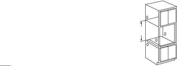
When installing the speedcook oven over a GE electric warming drawer, follow the product installation instructions.
•An anti-tip block must be installed at the rear of the warming drawer opening. Again, see Installation Instructions for complete details.
Electrical Requirements
Single Speedcook Installation
Product rating is 120/208 or 120/240V, 60 Hz, 30 amps. This product must be connected to a supply circuit of the proper voltage and frequency and protected by a time delay fuse or circuit breaker. The power supply should be brought to a separate 30 ampere branch circuit. Wire size must conform to the requirements of the National Electric Code or the prevailing local code.
Combined Speedcook and Wall Oven Installation
When installed in combination with a GE single wall oven, use separate electrical junction boxes, or
Install a single junction box connected to 50 amp. supply circuit or properly rated supply circuit.
•Refer to single oven installation instructions for electrical requirements of that product.
•These connections must be made by a qualified electrician. All electrical connections must meet National Electrical Code or prevailing local codes.
Combined Speedcook and Warming
Drawer Installation
When installing the speedcook oven over a GE electric warming drawer, a separate 120V, 60Hz, properly grounded receptacle must be installed. See instructions packed with the warming drawer.
WARNING: Electrical Shock Hazard
•The electrical power to the oven branch circuit must be shut off while line connections are being made.
•Use copper wiring only.
•Electrical ground is required on this appliance. The free end of the green wire (the ground wire) must be connected to a suitable ground. This wire must remain grounded to the oven.
•If cold water pipe is interrupted by plastic, nonmetallic gaskets, union connections, or other insulating materials, do not use for grounding.
•Do not ground to a gas pipe.
•Do not have a fuse in the NEUTRAL or GROUNDING circuit. A fuse in the NEUTRAL or GROUNDING circuit could result in an electrical shock.
•Check with a qualified electrician if you are in doubt as to whether the appliance is properly grounded.
Failure to follow these instructions could result in serious injury or death.
Install Junction Box
Note: The conduit is located at the top right on the back of the oven.
Locate and install the junction box within reach of the oven conduit:
•Through the left or right sides of the cabinet wall and into adjacent cabinet, or
•Through the cutout floor, or
•In the upper cabinet.
21"
Min.
GEA00359
Installation
Remove Packaging and Parts
1.Open the door and remove packing material with ceramic tray.
2.Locate Owner’s Kit in carton. Remove and save.
3.Locate box with metal trays in carton. Remove and save.
4.Locate parts package containing 5 mounting screws (4 required, 1 extra).
Caution: To protect the bottom trim, do not remove the styrofoam shipping base until the oven is slipped into the opening.
– 6 –

Route Conduit Through Cutout
Caution: Two people are required to lift the oven into the opening. Grasp the bottom at front and rear. Discard styrofoam base. Do not use the oven handle to lift the oven. Damage will occur!
1.With the oven in front of the cabinet opening, insert conduit into cabinet opening.
2.Lift the oven into the opening while continuing to feed the conduit in the direction of the installed junction box. Be sure the conduit does not get pinched between the back of the oven and the cabinet wall.
WARNING: Securely fasten oven to cabinet using the screws provided. Failure to do so could cause the oven to move or tip during use and result in personal injury.
3. Secure oven to cabinet with screws supplied.
Attachment |
Screws |
Styrofoam
Shipping Base
GEA00360
Secure Oven to Cabinet
1.Slide oven into the cabinet opening.
2.Drill 3/32-in. pilot holes into the cabinet frame through the 4 mounting holes in the oven’s front frame.
Secure Oven To Cabinet |
|
With Screws Provided |
GEA00361 |
Connect Electrical
WARNING: Electrical Shock Hazard
•Electrical ground is required on the appliance.
•Do not connect the electrical supply until appliance is permanently grounded.
•Disconnect power to the junction box before making the electrical connection.
•This appliance must be grounded to a metallic, permanent wiring system, or a grounding connector should be connected to the grounding terminal or wire lead on the appliance.
•Failure to do so could result in fire, personal injury, or electrical shock.
– 7 –
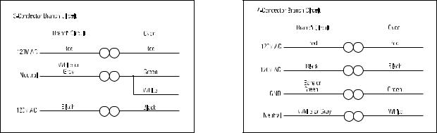
GEA00362 |
When Connecting to a 3-Conductor Branch Circuit:
1.Connect oven red lead to branch circuit red lead.
2.Connect oven black lead to branch circuit black lead.
3.Connect oven green ground lead and white lead to branch circuit neutral (white or gray).
GEA00363 |
When Connecting to a 4-Conductor Branch Circuit:
1.Connect oven red lead to branch circuit red lead.
2.Connect oven black lead to branch circuit black lead.
3.Break connection between oven white lead and oven green ground lead.
4.Connect oven white lead to branch circuit neutral lead (white or gray).
5.Connect oven green ground lead to branch circuit ground lead (green or bare copper).
– 8 –

Notes
– 9 –

|
|
Specifications |
|
|
|
|
15" |
|
|
|
27/32" |
|
(Recessed |
|
14-1/8" |
||
28-7/16" |
Portion) |
|
|
||
|
|
|
|
||
|
|
|
|
|
9/16" |
|
|
|
20-27/32" |
|
|
|
|
21-7/8" |
|
|
27/32" |
|
|
|
|
|
|
|
|
|
|
|
13" |
15-27/32" |
29-25/32" |
|
7/8" |
15/32" |
11/16" |
|
GEA00354 |
||||
|
|
||||
|
|
|
|
|
|
GEA00355
Nomenclature
S C B 2 0 0 0 C B B
|
|
|
|
|
|
|
|
|
|
|
|
|
|
|
|
Speedcook Oven |
|
|
|
|
|
|
|
|
|
||||||
Configuration |
|
|
|
|
|
|
|
|
|
|
|||||
|
|
|
|
|
|
|
|
|
|
||||||
A = Above the cooktop |
|
|
|
|
GEA00414 |
||||||||||
B = Built-in style |
|
|
|
|
|
||||||||||
Feature Package |
|
|
|
|
|
|
|||||||||
|
|
|
|
|
|
||||||||||
2000 = Color model |
|
|
|
|
|||||||||||
2001 = Stainless steel |
|
|
|
|
|||||||||||
Model Year Designator |
|
|
|
|
|
|
|
||||||||
|
|
|
|
|
|
|
|||||||||
Color |
|
|
|
|
|
|
|
||||||||
|
|
|
|
|
|
|
|||||||||
WW = White on white |
|
|
|
|
|||||||||||
BB = Black on black |
|
|
|
|
|||||||||||
CC = Bisque |
|
|
|
|
|||||||||||
AA = Almond on almond |
|
|
|
|
|||||||||||
SS = Stainless steel |
GEA00413 |
||||||||||||||
Cleaning
Clean the inside of the oven after each use. Some spatters can be removed with a paper towel, others may require a warm soapy cloth. Remove greasy spatters with a sudsy cloth, then rinse with a damp cloth.
Do not use abrasive cleaners or sharp utensils on oven walls. Never use a commercial oven cleaner on any part of your oven. Do not clean the inside of the oven with metal scouring pads.
Both the upper and lower halogen lamp covers must be kept free of grease and food spatterings in order to operate effectively. To clean the upper and lower lamp covers, remove the turntable. Wipe
the covers with a warm soapy cloth or plastic scrubbie.
GEA00412
For heavy burned-on soil, a cleaning scraper may be used to clean the halogen lamp covers.
Do not use cleaners containing ammonia or alcohol on the outside of the oven because they can damage the oven.
– 10 –

Warranty Information
Sales slip or cancelled check is required as proof of original purchase date to obtain service under warranty.
All warranty service is provided by our Factory Service Centers or an authorized Customer Care® technician.
For The Period Of: |
GE Will Replace: |
|
|
One Year |
Any part of the oven which fails due to a defect in materials or |
From the date of the original |
workmanship. During this full one-year warranty, GE will also |
purchase |
provide, free of charge, all labor and in-home service to replace |
|
the defective part. |
|
|
Ten Years |
The halogen speedcook lamps, if the halogen lamps fail due to |
From the second through the tenth |
a defect in materials or workmanship. During this full ten-year |
year from the date of original |
warranty, GE will also provide, free of charge, all labor and in- |
purchase |
home service to replace the defective part. |
|
|
Ten Years |
The magnetron tube, if the magnetron tube fails due to a defect |
From the second through the tenth |
in materials or workmanship. During this additional nine-year |
year from the date of original |
limited warranty, you will be responsible for any labor or in-home |
purchase |
service costs. |
|
|
What GE Will Not Cover:
•Service trips to your home to teach you how to use the product.
•Improper installation.
•Failure of the product if it is abused, misused, or used for other than the intended purpose or used commercially.
•Replacement of house fuses or resetting of circuit breakers.
•Damage to the product caused by accident, fire, floods, or acts of God.
•Incidental or consequential damage to personal property caused by possible defects with this applicance.
This warranty is extended to the original purchaser and any succeeding owner for products purchased for home use within the USA. In Alaska, the warranty excludes the cost of shipping or service calls to your home. Proof of the original purchase date is needed to obtain service under the warranty.
Some states do not allow the exclusion or limitation of incidental or consequential damages. This warranty gives you specific legal rights, and you may also have other rights which vary from state to state. To know what your legal rights are, consult your local or state consumer affairs office or your state’s Attorney General.
Warrantor: General Electric Company. Louisville, KY 40225
– 11 –
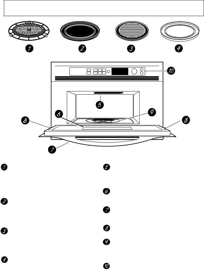
Overview of Advantium
Oven Rack (Turntable)
The oven rack (turntable) must always be in place, on the oven floor, for all cooking. Be sure the oven rack (turntable) is seated securely over the square spindle in the center of the oven.
Black Metal Tray/Baking Sheet
Used during speedcooking only. Put food directly on the black metal tray and place on the oven rack (turntable) when using the speedcook features.
Black Grill Tray/Baking Sheet
Used during speedcooking only. Put food directly on the black grill tray and place on the oven rack (turntable) when speedcooking foods you would normally cook on the grill.
White Ceramic Tray
Used during microwave oven cooking only.
Place on the oven rack (turntable) when using the microwave features. Place food or microwave-safe cookware directly on the tray.
Upper Halogen Lamp Assembly Used during speedcooking only. Two
1500-watt halogen lamps provide heat from the top of the oven cavity.
Window
Allows cooking to be viewed while keeping microwaves confined in the oven.
Door Handle
Pull to open the door. The door must be securely latched for the oven to operate.
Door Latches
Lower Halogen Lamp Assembly Used during speedcooking only. One
1500-watt halogen lamp provides heat from the bottom of the oven cavity.
Control Panel
The buttons used to operate the oven are located on the control panel.
– 12 –
Control Panel Features
SPEED |
POWER |
TIMER |
MICRO |
|
|
|
|
|
|
|
|
|
|
|
|
|
|
|
|
COOK |
LEVEL |
WAVE |
BACK |
|
|
|
|
|
|
|
|
|
|
|
|
|
|
|
|
|
|
|
|
|
|
|
|
|
|
|
|
|
|
|
|||||
|
|
|
|
|
|
|
|
|
|
|
|
|
|
|
|
||||
REPEAT LAST |
|
|
OVEN LIGHT |
|
|
|
|
|
|
|
|
|
|
|
|
|
|
|
|
|
|
|
|
|
|
|
|
|
|
|
|
|
|
|
|
|
|||
MANUAL |
OPTIONS |
HELP |
MICRO |
|
|
|
|
|
|
|
|
|
|
|
|
|
|
|
|
|
|
|
|
|
|
|
|
|
|
|
|
|
|
|
|
||||
COOK |
EXPRESS |
|
|
|
|
|
|
|
|
|
|
|
|
|
|
|
|
||
|
|
|
|
|
|
|
|
|
|
|
|
|
|
|
|
|
|
||
RECIPE |
|
|
|
|
|
|
|
|
|
|
|
|
|
|
|
|
|
|
|
|
|
|
|
|
|
|
|
|
|
|
|
|
|
T |
O |
S |
|
|
|
|
|
|
|
|
|
|
|
|
|
|
|
|
N |
|
|
EL |
|
|
|||
|
|
|
|
|
|
|
|
|
|
|
R |
|
|
|
|
|
E |
|
||
|
|
|
|
|
|
|
|
|
|
|
|
|
|
|
|
|
|
|
C |
|
|
|
|
|
|
|
|
|
|
|
|
U |
|
|
|
|
|
|
|
T |
|
|
|
|
|
|
|
|
|
|
|
|
T |
|
|
|
|
|
|
|
|
R |
|
|
|
|
|
|
|
|
|
|
|
P |
|
|
|
|
|
|
|
E |
|
|
|
|
|
|
|
|
|
|
|
|
|
|
|
|
|
|
|
|||
|
|
|
|
|
|
|
|
|
|
|
|
|
|
|
|
|
|
|||
|
|
|
|
|
|
|
|
|
|
|
|
|
|
|
|
|
|
|||
|
|
|
|
|
|
|
|
|
|
|
|
|
|
|
|
|
|
|||
|
|
|
|
|
|
|
|
|
|
|
|
|
|
|
|
|
|
|||
|
|
|
|
|
|
|
|
|
|
|
R |
|
|
|
|
|
|
|
|
|
|
|
|
|
|
|
|
|
|
|
|
E |
|
|
|
|
|
|
T |
|
|
|
|
|
|
|
|
|
|
|
|
|
|
|
|
|
N |
|
||||
|
|
|
|
|
|
|
|
|
|
|
|
S |
S |
|
|
|
||||
|
|
|
|
|
|
|
|
|
|
|
|
|
TOE |
|
|
|
||||
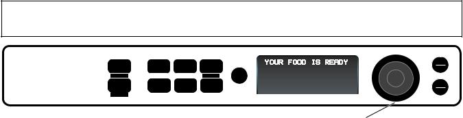
Selector Dial
START
PAUSE
CLEAR
OFF
GEA00416
SPEEDCOOK/REPEAT LAST
Press this button to access the preset speedcook menu. Press and hold for 3 seconds to repeat the last cooking selection.
MANUAL COOK/RECIPE
Press this button to set your own speedcook program.
POWER LEVEL
Press this button and turn/press the selector dial to change the speedcook upper lamps, lower lamp, and microwave power level before and during cooking.
OPTIONS
Press this button to set the Clock and access the
Beeper Volume, Clock Display ON/OFF, Display Scroll Speed features.
TIMER
Press this button to set the minute timer.
HELP
Press this button to find out more about your oven’s features.
MICROWAVE/OVEN LIGHT
Press this button to operate the microwave. Press while microwave cooking to light the oven cavity. The light will come on and will remain on until the end of the cooking cycle.
MICRO EXPRESS
Press for 30 seconds of microwave cooking time. Each press of the button adds an additional 30 seconds to the remaining cooking time. The oven starts immediately.
BACK
Press this button to step back one or more levels in the program process, such as when entering custom recipes.
SELECTOR DIAL-Turn to select, Press to enter
First turn then press the dial to make food selections. Also use the dial to increase (turn clockwise) or decrease (turn counterclockwise) cooking times.
START/PAUSE
Press this button to start or pause any cooking function.
CLEAR/OFF
Press this button to cancel all oven programs except the clock and timer.
– 13 –

Notes
– 14 –

How to Speedcook
To Select a Speedcook Program:
1.Press the SPEEDCOOK button.
2.Turn the selector dial to select the type of food you want. Press the dial to enter it.
3.Turn the dial to select the specific food. Press the dial to enter it.
4.Turn the dial to select the amount, size, and/or doneness (if required, the oven will prompt you). Press the dial after each selection.
5.Once the display shows “ADJUST TIME OR START,” press either the selector dial or START/PAUSE button to start cooking.
If the door is opened during cooking, the oven stops and “PAUSE” appears in the display. Close the door and press START/PAUSE to resume cooking. At any time during the cooking, you can turn the selector dial to change the cooking time. You can also change power levels.
Press the SPEEDCOOK button to begin:
Select TYPE:
PIZZA
OVEN LOCKED SELECT |
MUTE TIMER |
1.“Select TYPE [of food]:”
Turn to “PIZZA” and then press the selector dial to enter selection.
Select PIZZA type:
REG. CRUST, FROZEN
OVEN LOCKED SELECT |
MUTE TIMER |
2.“Select PIZZA type:” Turn to “REG. CRUST,
FROZEN” and then press the selector dial to enter selection.
Use ROUND METAL TRAY |
ADJUST TIME or START |
||
10:00 U=08 L=07 |
M=02 |
10:00 U=08 L=07 |
M=02 |
OVEN LOCKED SELECT |
MUTE TIMER |
OVEN LOCKED SELECT |
MUTE TIMER |
4. After entering the size, you will |
5. “ADJUST TIME or START” |
||
see a message instructing you |
appears. Press the START |
||
to “Use ROUND METAL TRAY.” |
button or selector dial to begin |
||
Be sure to use the metal tray |
cooking. |
|
|
that came with the Advantium. |
|
|
|
GEA00417
Select SIZE:
Regular (12")
OVEN LOCKED SELECT |
MUTE TIMER |
GEA00418
3.“Select SIZE:”
Turn to “Regular (12”)” and then press the selector dial to enter selection.
REG, CRUST, FROZEN 09:59
OVEN LOCKED SELECT |
MUTE TIMER |
GEA00419
6.Once the oven starts cooking, you will see your selection in the display with remaining cooking time counting down.
OPTIMIZING COOK TIME 9:55
OVEN LOCKED SELECT |
MUTE TIMER |
7.After approximately 3-5 sec., the cook time may be adjusted up or down to compensate for variations in line voltage.
CHECK for DONENESS 4:00
OVEN LOCKED SELECT |
MUTE TIMER |
8.Minutes before cooking ends, “CHECK for DONENESS” appears. Power shuts off until restarted (START).
YOUR FOOD IS READY
OVEN LOCKED SELECT |
MUTE TIMER |
GEA00420
9.Minutes later, enjoy pizza with a crispy brown crust and golden melted cheese. It doesn’t get much easier than this.
– 15 –

Operating Characteristics
Table of Contents
Power Levels . . . . . . . . . . . . . . . . . . . . . . . . . . . . . . . . . . . . . . . . . . . . . . . . . . . 17
Upper Halogen Lamp Pair . . . . . . . . . . . . . . . . . . . . . . . . . . . . . . . . . . . . . . . 17
Lower Halogen Lamp . . . . . . . . . . . . . . . . . . . . . . . . . . . . . . . . . . . . . . . . . . 17
Microwave Energy . . . . . . . . . . . . . . . . . . . . . . . . . . . . . . . . . . . . . . . . . . . . . 18
Voltage Compensation . . . . . . . . . . . . . . . . . . . . . . . . . . . . . . . . . . . . . . . . . . . 18
Upper Halogen Lamp Balance . . . . . . . . . . . . . . . . . . . . . . . . . . . . . . . . . . . . . 18
Thermal Compensation . . . . . . . . . . . . . . . . . . . . . . . . . . . . . . . . . . . . . . . . . . |
19 |
Thermal Compensation Test . . . . . . . . . . . . . . . . . . . . . . . . . . . . . . . . . . . . . 21
Thermal Protection . . . . . . . . . . . . . . . . . . . . . . . . . . . . . . . . . . . . . . . . . . . . . . 21
Thermal Safety . . . . . . . . . . . . . . . . . . . . . . . . . . . . . . . . . . . . . . . . . . . . . . . . . . 22
Damper Door Assembly . . . . . . . . . . . . . . . . . . . . . . . . . . . . . . . . . . . . . . . . . . 22
Damper Door Switch . . . . . . . . . . . . . . . . . . . . . . . . . . . . . . . . . . . . . . . . . . . 22
Damper Door Open . . . . . . . . . . . . . . . . . . . . . . . . . . . . . . . . . . . . . . . . . . . . 23
Damper Door Closed . . . . . . . . . . . . . . . . . . . . . . . . . . . . . . . . . . . . . . . . . . . 23
Oven Cavity Lamps . . . . . . . . . . . . . . . . . . . . . . . . . . . . . . . . . . . . . . . . . . . . 23
Thermal Fuse . . . . . . . . . . . . . . . . . . . . . . . . . . . . . . . . . . . . . . . . . . . . . . . . . 23
Air Flow . . . . . . . . . . . . . . . . . . . . . . . . . . . . . . . . . . . . . . . . . . . . . . . . . . . . . . . |
23 |
Exhaust Motor . . . . . . . . . . . . . . . . . . . . . . . . . . . . . . . . . . . . . . . . . . . . . . . . 24
Upper and Lower Halogen Blowers . . . . . . . . . . . . . . . . . . . . . . . . . . . . . . . 24
Magnetron Blower Assembly . . . . . . . . . . . . . . . . . . . . . . . . . . . . . . . . . . . . 24
Air Flow Diagram . . . . . . . . . . . . . . . . . . . . . . . . . . . . . . . . . . . . . . . . . . . . . . 25
– 16 –
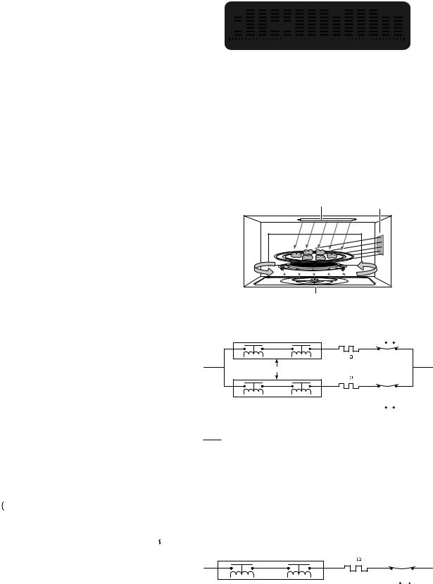
Power Levels
Advantium uses power from high-intensity halogen lamps, as well as microwave energy, to cook foods evenly and quickly (average of one-fourth the time of a conventional oven) to seal in moisture and flavor.
Power levels are selected with the selector dial and can be adjusted before cooking or during cooking. When using preset menu foods, the power levels are already selected for you. However, power levels can be adjusted when cooking both preset menu food and when manual cooking.
Power levels are adjusted independently for the upper halogen lamps (pair), lower halogen lamp (single), and microwave energy. When selecting an upper halogen lamp power level, the power level can only be selected for the pair. You can not select power levels for the upper rear and upper front independently.
Power levels of 0 to 10 can be selected for the upper halogen lamps (pair), lower halogen lamp, and microwave energy. The power levels control the percentage of ON time for the upper halogen lamp pair, the lower halogen lamp, and microwave high voltage circuit.
The programming on the smart board which controls the upper and lower halogen lamps, as well as the high voltage/magnetron circuits, operates on a duty cycle of 32 seconds. This means the power level you select for each component controls the percentage of ON time during each 32-second period of time.
In the following example, the upper halogen lamps would cycle for 80% of each 32-second period, the lower would cycle at 50% of each 32-second period, and the microwave high voltage circuit would be energized for 30% of each 32-second period.
|
|
|
|
|
|
|
|
|
|
|
|
|
|
|
|
|
|
|
|
|
|
|
|
|
|
|
|
|
|
U=08 |
|
|
|
|
U=08 |
|
|
|
U=08 |
|
|
|
|
|
|
||||||||
% ON |
|
|
|
|
|
|
|
|
|
|
|
|
|
|
|
|
|
|
|
|
|
|
|
|
|
|
|
|
L=05 |
|
|
|
|
|
L=05 |
|
|
|
|
L=05 |
|
|
|
|
|
|
|
||||||
TIME |
|
|
|
|
|
|
|
|
|
|
|
|
|
|
|
|
|
|
|
|
|
|
|
|
|
|
|
M=03 |
|
|
|
|
|
|
|
M=03 |
|
|
|
|
|
M=03 |
|
|
|
|
|
|
|
|
|||
|
|
|
|
|
|
|
|
|
|
|
|
|
|
|
|
|
|
|
|
|
||||||
|
|
|
|
|
|
|
|
|
|
|
|
|
|
|
|
|
|
|
|
|
|
|
|
|
|
|
|
|
|
|
|
|
|
|
|
|
|
|
|
|
|
|
|
|
|
|
|
|
|
|
|
|
|
|
30% |
50% |
80% |
|
30% |
50% |
80% |
|
30% |
50% |
80% |
|
|
|
||||||||||||
|
|
|
|
|
|
|
|
|
|
|
|
|
|
|
|
|
|
|
|
|
|
|
|
|||
|
0 |
|
|
|
|
|
|
|
32 Secs |
|
|
|
64 Secs |
|
|
|
96 S |
|||||||||
|
|
|
|
|
|
|
|
32 Second Duty Cycles |
|
GEA00421 |
||||||||||||||||
Example: Upper element set at 80% (U=08), lower element set at 50% (L=05), and microwave set at 30% (M=03).
 Select UPPER
  POWER:

 5:00
5:00
 U=08 L=05 M=03
OVEN LOCKED SELECT |
REM NITE |
MUTE TIMER |
GEA00422
Upper Halogen Lamp Pair (U=)
The upper halogen lamps provide radiant heat to the top surface of the food. Select a higher setting for thin foods requiring a golden brown top (example: fish fillets, toast, boneless chicken breasts). Select a lower setting for thicker foods and foods with high sugar or fat content (example: cakes, roasts).
Upper Halogen
Pair (U=) Microwave
(M=)
|
Lower Halogen |
|
|
|
|
Lamp (L=) |
|
GEA00423 |
|
UPPER AIR GAP |
UPPER HEATER |
UPPER HEATER |
UHC TCO |
|
RELAY (RY23) |
RELAY (RY18) |
ONE SHOT |
|
|
CENTER |
|
|||
|
|
(293 /32 F) |
|
|
|
|
|
|
|
|
|
1.2 |
|
|
N |
|
|
|
L2 |
RELAY BOARD |
|
|
|
|
|
|
1.2 |
|
|
UPPER AIR GAP |
UPPER HEATER |
UPPER HEATER |
UHE TCO |
|
EXTERIOR |
ONE SHOT |
|
||
RELAY (RY22) |
EXTERIOR |
|
||
|
(293 /32 F) |
|
||
|
RELAY (RY19) |
|
GEA00396 |
|
|
|
|
||
Lower Halogen Lamp (L=)
The lower halogen lamp provides cooking from below to heat the cooking surface (cooking trays and cookware). Select a higher setting for thick or dense foods that may not cook quickly in the center (example: casseroles). Select a lower setting for thin foods (example: cookies) and foods containing high fat or sugar content (example: pastries, cakes).
RELAY BOARD |
1.2 |
|
||
N |
|
|
L1 |
|
|
|
LOWER |
LH TCO |
|
|
|
ONE SHOT |
||
LOWER HEATER AIR |
LOWER HEATER |
HEATER |
||
(293 /32 F) |
||||
GAP RELAY (RY21) |
RELAY (RY20) |
|
|
|
|
|
|
GEA00397 |
|
– 17 –
Microwave Energy (M=)
Microwave energy is provided by the high voltage/ magnetron circuit and directed via the wave guide directly into the oven cavity. As the food rotates on the oven turntable, microwave energy is evenly distributed to all portions of the food. Select a higher setting to shorten cooking time for dense or heavy foods (example: casseroles, whole chicken). Select a lower setting for delicate foods (example: cakes, breads, souffles) or foods requiring longer cooking times for tender results (example: stew, pot roast).
CONTROL BOARD |
|
|
|
|
|
|
N |
|
|
|
|
L1 |
|
|
HV PRIMARY |
PRIMARY |
FUSE |
MGT TCO |
CAVITY TCO |
|
|
ONE SHOT |
|||||
SECONDARY |
WINDING |
INTERLOCK |
(20 AMPS) |
(302 /140 F) |
||
(302 /140 F) |
||||||
INTERLOCK RELAY |
(MAGNETRON) |
|
|
|
||
|
|
|
GEA00398 |
|||
|
|
|
|
|
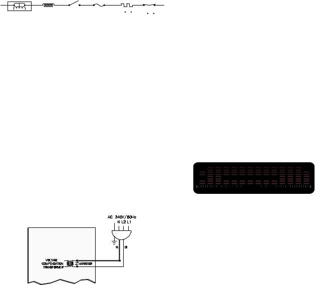
Voltage Compensation
Note: Voltage compensation only occurs during speedcook operation (preselect menu item). In other words, when cooking with manual cook, voltage compensation does not occur. When using speedcook, you are selecting preselected items from a menu. These items require compensation for accurate and consistent cooking results.
Voltage fluctuations in the power lines can cause inconsistencies in cooking. Advantium automatically measures line voltage at the start of each speedcooking selection and adjusts the cooking time to achieve consistent quality results.
Line voltage is monitored by the voltage compensation transformer, which is located on the smart board. This transformer monitors the voltage from L2 to neutral.
SMART BOARD
BN
Y
Voltage Compensation Circuit
GEA00424
The optimal line voltage, where no voltage compensation occurs, is 120 VAC. Above 120 VAC, time is subtracted from the recipe.
Below 120 VAC, time is added to the recipe. The amount of voltage compensation required is dependent upon the incoming voltage at the start of the cooking cycle, and the particular
speedcooking selection that is chosen. The chart below shows the predicted compensation times based on a 5-minute speedcook selection (such as: Biscuits, Refr; Large; 8 biscuits).
VOLTAGE |
TIME (secs) |
L2 to N |
COMPENSATION |
|
|
108 |
60.0 |
|
|
110 |
47.9 |
|
|
112 |
36.7 |
|
|
114 |
26.3 |
|
|
116 |
16.7 |
|
|
118 |
7.9 |
|
|
120 |
0.0 |
|
|
122 |
-7.1 |
|
|
124 |
-13.3 |
|
|
126 |
-18.8 |
|
|
128 |
-23.3 |
|
|
130 |
-27.1 |
|
|
132 |
-30.0 |
|
|
Voltage compensation occurs after approximately 5 seconds of cooking operation. The display will show “OPTIMIZING COOK TIME.” The time will flash and then display the new adjusted time, based on the amount of voltage compensation required.
 OPTIMIZING COOK TIME
 9:55
9:55


OVEN LOCKED SELECT |
MUTE TIMER |
GEA00425
Voltage compensation only occurs during speedcook operation and only occurs once during the cooking cycle (at initial start of speedcook operation).
Upper Halogen Lamp Balance
As stated previously, the upper halogen lamps operate together at the same power level. However, in order to provide even (balanced) cooking performance, the upper rear halogen lamp will always cycle at 85% of the upper front halogen lamp. In other words, if the upper halogen lamps are set at power level 10 (U=10), you would expect both elements to operate at 100% of each 32-second duty cycle. Instead, the upper rear halogen will cycle at 85% of power level 10, or
– 18 –
 Loading...