


 Loading...
GE ZGU122L, ZGG542LC, ZGG300NC, ZGG420LC, ZGG420NC User Manual
...Installation
Instructions
Professional Outdoor Grills
and Cooktop
Tables de cuisson et barbecues de plein air professionnels
Instructions d’installation
La section française commence à la page 23
Parrillas y estufa profesionales para el aire libre
Instrucciones de instalación
La sección en español empieza en la página 45
31-10702-1
06-09 JR

Installation Instructions
BEFORE YOU BEGIN
Read these instructions completely and carefully.
• IMPORTANT— Save these instructions for local inspector’s use.
• IMPORTANT— Observe all governing codes and ordinances.
•Note to Installer — Be sure to leave these instructions with the Consumer.
•Note to Consumer — Keep these instructions with your Owner’s Manual for future reference.
If you have questions concerning the installation of this product, call the GE Answer Center® Consumer Information Service at 800.626.2000, 8 a.m. to
10 p.m. EST, Monday through Friday, and 8 a.m. to 7 p.m. EST, Saturday.
If you received a damaged grill or cooktop, you should contact your dealer.
Installation of this outdoor grill or cooktop requires basic mechanical skills. Proper installation is the responsibility of the installer.
For Monogram local service in your area, call 1.800.444.1845.
For Monogram service in Canada, call 1.800.561.3344.
For Monogram Parts and Accessories, call 1.800.626.2002.
FOR YOUR SAFETY: Do not use the
grill or cooktop in a space where gasoline or other liquids having flammable vapors are stored or used.
The installation must conform to local codes or, in the absence of local codes, with either the National Fuel Gas Code, ANSI Z223.1/NFPA 54, National Gas and propane Installation Code.
 WARNING:
•For outdoor use only. Use this outdoor grill or cooktop only in the manner intended by the manufacturer.
•This outdoor cooking gas appliance is not intended to be installed in or on recreational vehicles and/or boats.
•Do not use the grill in an explosive atmosphere. Keep the grill away from areas where gasoline or other flammable liquids and vapors are stored or being used.
•Observe proper clearances to combustible materials at all times.
•Do not use a rusty or damaged LP tank.
•Never substitute gases (natural for LP or LP for natural). These grills are factory-set for LP or natural gas. Order the model for the installation situation.
•When storing the grill indoors, disconnect the LP tank. Store the tank outdoors in a well ventilated area.
•Do not store additional LP tanks in or near the gas grill.
•Follow the guidelines on the LP tank for proper storage, transport and handling.
IF YOU SMELL GAS:
•Shut off gas to appliance.
•Extinguish any open flame.
•Open lid.
•If odor continues, keep away from the appliance and immediately call your gas supplier or fire department.
BEFORE LIGHTING:
1.Read instructions before lighting.
2.Open lid during lighting.
3.If ignition does not occur in 5 seconds, turn the burner control(s) to OFF, wait 5 minutes and repeat the lighting.
2
Installation Instructions
FOR OUTDOOR USE ONLY
IMPROPER INSTALLATION, ADJUSTMENT, ALTERATION, SERVICE OR MAINTENANCE CAN CAUSE PROPERTY DAMAGE, INJURY OR DEATH. READ THIS MANUAL THOROUGHLY BEFORE INSTALLATION, USE OR SERVICING THIS EQUIPMENT.
CALIFORNIA
PROPOSITION 65
 WARNING: The burning of gas cooking fuel generates some by-products, which are on the list of substances, which are known by the State of California to cause cancer or reproductive harm. California law requires businesses to warn customers of potential exposure to such substances. To minimize exposure to the substances, always operate this unit according to the Use and Care instructions provided with this unit. Be certain to provide adequate ventilation when cooking. California Proposition 65 lists “Silica, crystalline” which is used in one of the components of the IR burner, as an agent known to the state of California to cause cancer.
In Massachusetts: All gas products must be installed using a “Massachusetts” licensed plumber or gasfitter. A “T” handle type manual gas valve must be installed in the gas supply line to this appliance. This applies to permanently installed natural gas and propane installations. This does not apply to propane portable installations using a 20-pound tank (not included) plus regulator and hose assembly, which is supplied with propane gas grills.
INSECT WARNING!
Spiders and insects can nest in the burners of this and any other grill and cause the gas to flow from the front of the burner. This is a very dangerous condition which can cause fire to occur behind the valve panel, thereby damaging the grill and making it unsafe to operate. Inspect the grill twice a year or immediately if any symptoms appear.
CODE COMPLIANCE
Test in accordance with ANSI Z21.58 latest edition standard for outdoor cooking gas appliances. This grill is for outdoor use only. Check local
building codes for the proper method of installation. In the absence of local codes, this unit should be installed in accordance with the National Fuel Gas Code No. Z223 latest edition and the National Electrical Code ANSI/NFPA no. 70, latest edition.
 CAUTION: All outdoor grills are extremely heavy. Two people are required to lift and place a built-in grill into an enclosure. At least two people are also required to remove a grill on cart from the skid.
3
Design Information
CONTENTS |
|
......................................................................Tools Required |
12 |
|
Design Information |
|
Materials Required .............................................................. |
12 |
|
|
Parts Provided |
12 |
||
Models Available |
4 |
|||
Remove Packaging from Cart Models |
13, 14 |
|||
Product Dimensions and Clearances |
5–7 |
|||
Remove Packaging from Built-In Models |
15 |
|||
Accessories |
8 |
|||
|
|
|||
Accessory Product Dimensions........................................ |
8 |
Installation Instructions |
|
|
Installation Preparation |
|
LP Tank Tie-Down ................................................................ |
16 |
|
|
Tank Drawer with LP Tank Retainer Loop |
16 |
||
Advance Planning |
9 |
|||
LP Gas Grill Connections |
|
|||
Choosing the Location |
9 |
|
||
to a Grill or Cooktop |
16, 17 |
|||
Electrical Supply Requirements |
10 |
|||
Natural Gas Grill Connections |
17 |
|||
Gas Supply Requirements |
10 |
|||
Leak Testing |
18 |
|||
Outdoor Grill, Cooktop and |
|
|||
|
Make Electrical Connections |
19 |
||
Accessory Cutout Dimensions |
11 |
|||
|
|
|||
|
|
|
|
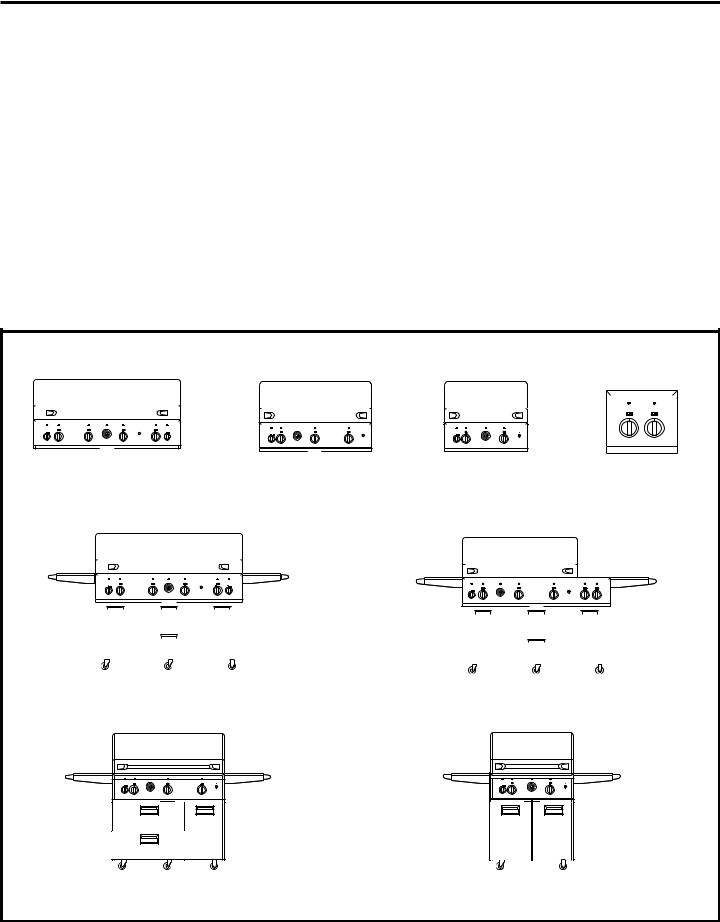
MODELS AVAILABLE (select the model according to the type of gas)
|
|
|
|
|
|
|
|
|
|
|
|
|
|
|
|
|
|
|
|
|
|
|
|
|
|
|
|
|
|
|
|
|
|
|
|
|
|
|
|
|
|
|
|
|
|
|
|
|
|
|
|
|
|
|
|
|
|
|
|
|
|
|
|
|
|
|
|
|
|
|
|
|
|
|
|
|
|
|
|
|
|
|
|
|
|
|
|
|
|
|
|
|
|
|
|
|
|
|
|
|
|
|
|
|
|
|
|
|
|
|
|
|
|
|
|
|
|
|
|
|
|
|
|
|
|
|
|
|
|
|
|
|
|
|
|
|
|
|
|
|
|
|
|
|
|
|
|
|
|
|
|
|
|
|
|
|
|
|
|
|
|
|
|
|
|
|
|
|
|
|
|
|
|
|
|
|
|
|
|
|
|
|
|
|
|
|
|
|
|
|
|
|
|
|
|
|
|
|
|
|
|
|
|
|
|
|
|
|
|
|
|
|
|
|
|
|
|
|
|
|
|
|
|
|
|
|
|
|
|
|
|
|
|
|
|
|
|
|
|
|
|
|
|
|
|
|
|
|
|
|
|
|
|
|
|
|
|
|
|
|
|
|
|
|
|
|
|
|
|
|
|
|
|
|
|
|
|
|
|
|
|
|
|
|
|
|
|
|
|
|
|
|
|
|
|
|
|
|
|
|
|
|
|
|
|
|
|
|
|
|
|
|
|
|
|
|
|
|
|
|
|
|
|
|
|
|
|
|
|
|
|
|
|
|
|
|
|
|
|
|
|
|
|
|
|
|
|
|
|
|
|
|
|
|
|
|
|
|
|
|
|
|
|
|
|
|
|
|
|
|
|
|
|
|
|
|
|
|
|
|
|
|
|
|
|
|
|
|
|
|
|
|
|
|
|
|
|
|
|
|
|
|
|
|
|
|
|
|
|
|
|
|
|
|
|
|
|
|
|
|
|
|
|
|
|
|
|
|
|
|
|
|
|
|
|
|
|
|
|
|
|
|
|
|
|
|
|
|
|
|
|
|
|
|
|
|
|
|
|
|
|
|
|
|
|
|
|
|
|
|
|
|
|
|
|
|
|
|
|
|
|
|
|
|
|
|
|
|
|
|
|
|
|
|
|
|
|
|
|
|
|
|
|
|
|
|
|
|
|
|
|
|
|
|
|
|
|
|
|
|
|
|
|
|
|
|
|
|
|
|
|
|
|
|
|
|
|
|
|
|
|
|
|
|
|
|
|
|
|
|
|
|
|
|
|
|
|
|
|
|
|
|
|
|
|
|
|
|
|
|
|
|
|
|
|
|
|
|
|
|
|
|
|
|
|
|
|
|
|
|
|
|
|
|
|
|
|
|
|
|
|
|
|
|
|
|
|
|
|
|
|
|
|
|
|
|
|
|
|
|
|
|
|
|
|
|
|
|
|
|
|
|
|
|
|
|
|
|
|
|
|
|
|
|
|
|
|
|
|
|
|
|
|
|
|
|
|
|
|
|
|
|
|
|
|
|
|
|
|
|
|
|
|
|
|
|
|
|
|
|
|
|
|
|
|
|
|
|
|
|
|
|
|
|
|
|
|
|
|
|
|
|
|
|
|
|
|
|
|
|
|
|
|
|
|
|
|
|
|
|
|
|
|
|
|
|
|
|
|
|
|
|
|
|
|
|
|
|
|
|
|
|
|
|
|
|
|
|
|
|
|
|
|
|
|
|
|
|
|
|
|
|
|
|
|
|
|
|
|
|
|
|
|
|
|
|
|
|
|
|
|
|
|
|
|
|
|
|
|
|
|
|
|
|
|
|
|
|
|
|
|
|
|
|
|
|
|
|
|
|
|
|
|
|
|
|
|
|
|
|
|
|
|
|
|
|
|
|
|
|
|
|
|
|
|
|
|
|
|
|
|
|
|
|
|
|
|
|
|
|
|
|
|
|
|
|
|
|
|
|
|
|
|
|
|
|
|
|
|
|
|
|
|
|
|
|
|
|
|
|
|
|
|
|
|
|
|
|
|
|
|
|
|
|
|
|
|
|
|
|
|
|
|
|
|
|
|
|
|
|
|
|
|
|
|
|
|
|
|
|
|
|
|
|
|
|
|
|
|
|
|
|
|
|
|
|
|
|
|
|
|
|
|
|
|
|
|
|
|
|
|
|
|
|
|
|
|
|
|
|
|
|
|
|
|
|
|
|
|
|
|
|
|
|
|
|
|
|
|
|
|
|
|
|
|
|
|
|
|
|
|
|
|
|
|
|
|
|
|
|
|
|
|
|
|
|
|
|
|
|
|
|
|
|
|
|
|
|
|
|
|
|
|
|
|
|
|
|
|
|
|
|
|
|
|
|
|
|
|
|
|
|
|
|
|
|
|
|
|
|
|
|
|
|
|
|
|
|
|
|
|
|
|
|
|
|
|
|
|
|
|
|
|
|
|
|
|
|
|
|
|
|
|
|
|
|
|
|
|
|
|
|
|
|
|
|
|
|
|
|
|
|
|
|
|
|
|
|
|
|
|
|
|
|
|
|
|
|
|
|
|
|
|
|
|
|
|
|
|
|
|
|
|
|
|
|
|
|
|
|
|
|
|
|
|
|
|
|
|
|
|
|
|
|
|
|
|
|
|
|
|
|
|
|
|
|
|
|
|
|
|
|
|
|
|
|
|
|
|
|
|
|
|
|
|
|
|
|
|
|
|
|
|
|
|
|
|
|
|
|
|
|
|
|
|
|
|
ZGG300NB, 30" Built-In |
|
|
|
12" Outdoor Cooktop |
|
|||||||||||||||||||||||||||||||
|
ZGG540NB, 54" Built-In Natural Gas |
|
|
|
ZGG420NB, 42" Built-In Natural Gas |
|
|
|||||||||||||||||||||||||||||||||||||||||||||||||||||||||||||||||||||||||||
|
|
|
|
|
|
|
|
|
|
Natural Gas |
|
|
|
|
|
|
|
|
with 2 Burners |
|
||||||||||||||||||||||||||||||||||||||||||||||||||||||||||||||
|
|
ZGG540LB, 54" Built-In LP Gas |
|
|
|
|
|
|
|
ZGG420LB, 42" Built-In LP Gas |
|
|
|
|
|
|
|
|
|
|
|
|
|
|||||||||||||||||||||||||||||||||||||||||||||||||||||||||||
|
|
|
|
|
|
|
|
|
|
ZGG300LB, 30" Built-In |
|
|
|
|
|
ZGU122N, Natural Gas |
|
|||||||||||||||||||||||||||||||||||||||||||||||||||||||||||||||||
|
|
|
|
|
|
|
|
|
|
|
|
|
|
|
|
|
|
|
|
|
|
|
|
|
|
|
|
|
|
|
|
|
|
|
|
|
|
|
|
|
|
|
|
|
|
|
|
|
|
|||||||||||||||||||||||||||||||||
|
|
|
|
|
|
|
|
|
|
|
|
|
|
|
|
|
|
|
|
|
|
|
|
|
|
|
|
|
|
|
|
|
|
|
|
|
|
|
|
|
|
|
|
|
|
|
|
|
|
|
|
|
|
|
LP Gas |
|
|
|
|
|
ZGU122L, LP Gas |
|
||||||||||||||||||||
|
|
|
|
|
|
|
|
|
|
|
|
|
|
|
|
|
|
|
|
|
|
|
|
|
|
|
|
|
|
|
|
|
|
|
|
|
|
|
|
|
|
|
|
|
|
|
|
|
|
|
|
|
|
|
|
|
|
|
||||||||||||||||||||||||
|
|
|
|
|
|
|
|
|
|
|
|
|
|
|
|
|
|
|
|
|
|
|
|
|
|
|
|
|
|
|
|
|
|
|
|
|
|
|
|
|
|
|
|
|
|
|
|
|
|
|
|
|
|
|
|
|
|
|
|
|
|
|
|
|
|
|
|
|
|
|
|
|
|
|
|
|
|
|
|
|
|
|
|
|
|
|
|
|
|
|
|
|
|
|
|
|
|
|
|
|
|
|
|
|
|
|
|
|
|
|
|
|
|
|
|
|
|
|
|
|
|
|
|
|
|
|
|
|
|
|
|
|
|
|
|
|
|
|
|
|
|
|
|
|
|
|
|
|
|
|
|
|
|
|
|
|
|
|
|
|
|
|
|
|
|
|
|
|
|
|
|
|
|
|
|
|
|
|
|
|
|
|
|
|
|
|
|
|
|
|
|
|
|
|
|
|
|
|
|
|
|
|
|
|
|
|
|
|
|
|
|
|
|
|
|
|
|
|
|
|
|
|
|
|
|
|
|
|
|
|
|
|
|
|
|
|
|
|
|
|
|
|
|
|
|
|
|
|
|
|
|
|
|
|
|
|
|
|
|
|
|
|
|
|
|
|
|
|
|
|
|
|
|
|
|
|
|
|
|
|
|
|
|
|
|
|
|
|
|
|
|
|
|
|
|
|
|
|
|
|
|
|
|
|
|
|
|
|
|
|
|
|
|
|
|
|
|
|
|
|
|
|
|
|
|
|
|
|
|
|
|
|
|
|
|
|
|
|
|
|
|
|
|
|
|
|
|
|
|
|
|
|
|
|
|
|
|
|
|
|
|
|
|
|
|
|
|
|
|
|
|
|
|
|
|
|
|
|
|
|
|
|
|
|
|
|
|
|
|
|
|
|
|
|
|
|
|
|
|
|
|
|
|
|
|
|
|
|
|
|
|
|
|
|
|
|
|
|
|
|
|
|
|
|
|
|
|
|
|
|
|
|
|
|
|
|
|
|
|
|
|
|
|
|
|
|
|
|
|
|
|
|
|
|
|
|
|
|
|
|
|
|
|
|
|
|
|
|
|
|
|
|
|
|
|
|
|
|
|
|
|
|
|
|
|
|
|
|
|
|
|
|
|
|
|
|
|
|
|
|
|
|
|
|
|
|
|
|
|
|
|
|
|
|
|
|
|
|
|
|
|
|
|
|
|
|
|
|
|
|
|
|
|
|
|
|
|
|
|
|
|
|
|
|
|
|
|
|
|
|
|
|
|
|
|
|
|
|
|
|
|
|
|
|
|
|
|
|
|
|
|
|
|
|
|
|
|
|
|
|
|
|
|
|
|
|
|
|
|
|
|
|
|
|
|
|
|
|
|
|
|
|
|
|
|
|
|
|
|
|
|
|
|
|
|
|
|
|
|
|
|
|
|
|
|
|
|
|
|
|
|
|
|
|
|
|
|
|
|
|
|
|
|
|
|
|
|
|
|
|
|
|
|
|
|
|
|
|
|
|
|
|
|
|
|
|
|
|
|
|
|
|
|
|
|
|
|
|
|
|
|
|
|
|
|
|
|
|
|
|
|
|
|
|
|
|
|
|
|
|
|
|
|
|
|
|
|
|
|
|
|
|
|
|
|
|
|
|
|
|
|
|
|
|
|
|
|
|
|
|
|
|
|
|
|
|
|
|
|
|
|
|
|
|
|
|
|
|
|
|
|
|
|
|
|
|
|
|
|
|
|
|
|
|
|
|
|
|
|
|
|
|
|
|
|
|
|
|
|
|
|
|
|
|
|
|
|
|
|
|
|
|
|
|
|
|
|
|
|
|
|
|
|
|
|
|
|
|
|
|
|
|
|
|
|
|
|
|
|
|
|
|
|
|
|
|
|
|
|
|
|
|
|
|
|
|
|
|
|
|
|
|
|
|
|
|
|
|
|
|
|
|
|
|
|
|
|
|
|
|
|
|
|
|
|
|
|
|
|
|
|
|
|
|
|
|
|
|
|
|
|
|
|
|
|
|
|
|
|
|
|
|
|
|
|
|
|
|
|
|
|
|
|
|
|
|
|
|
|
|
|
|
|
|
|
|
|
|
|
|
|
|
|
|
|
|
|
|
|
|
|
|
|
|
|
|
|
|
|
|
|
|
|
|
|
|
|
|
|
|
|
|
|
|
|
|
|
|
|
|
|
|
|
|
|
|
|
|
|
|
|
|
|
|
|
|
|
|
|
|
|
|
|
|
|
|
|
|
|
|
|
|
|
|
|
|
|
|
|
|
|
|
|
|
|
|
|
|
|
|
|
|
|
|
|
|
|
|
|
|
|
|
|
|
|
|
|
|
|
|
|
|
|
|
|
|
|
|
|
|
|
|
|
|
|
|
|
|
|
|
|
|
|
|
|
|
|
|
|
|
|
|
|
|
|
|
|
|
|
|
|
|
|
|
|
|
|
|
|
|
|
|
|
|
|
|
|
|
|
|
|
|
|
|
|
|
|
|
|
|
|
|
|
|
|
|
|
|
|
|
|
|
|
|
|
|
|
|
|
|
|
|
|
|
|
|
|
|
|
|
|
|
|
|
|
|
|
|
|
|
|
|
|
|
|
|
|
|
|
|
|
|
|
|
|
|
|
|
|
|
|
ZGG540NC, 54" Natural Gas Grill with Cart ZGG540LC, 54" LP Gas Grill with Cart
ZGG542NC, 54" Natural Gas Grill with Cart and 2 Side Burners ZGG542LC, 54" LP Gas Grill with Cart and 2 Side Burners
ZGG420NC, 42" Natural Gas Grill with Cart ZGG420LC, 42" LP Gas Grill with Cart
ZGG300NC, 30" Natural Gas Grill with Cart ZGG300LC, 30" LP Gas Grill with Cart
4
Design Information
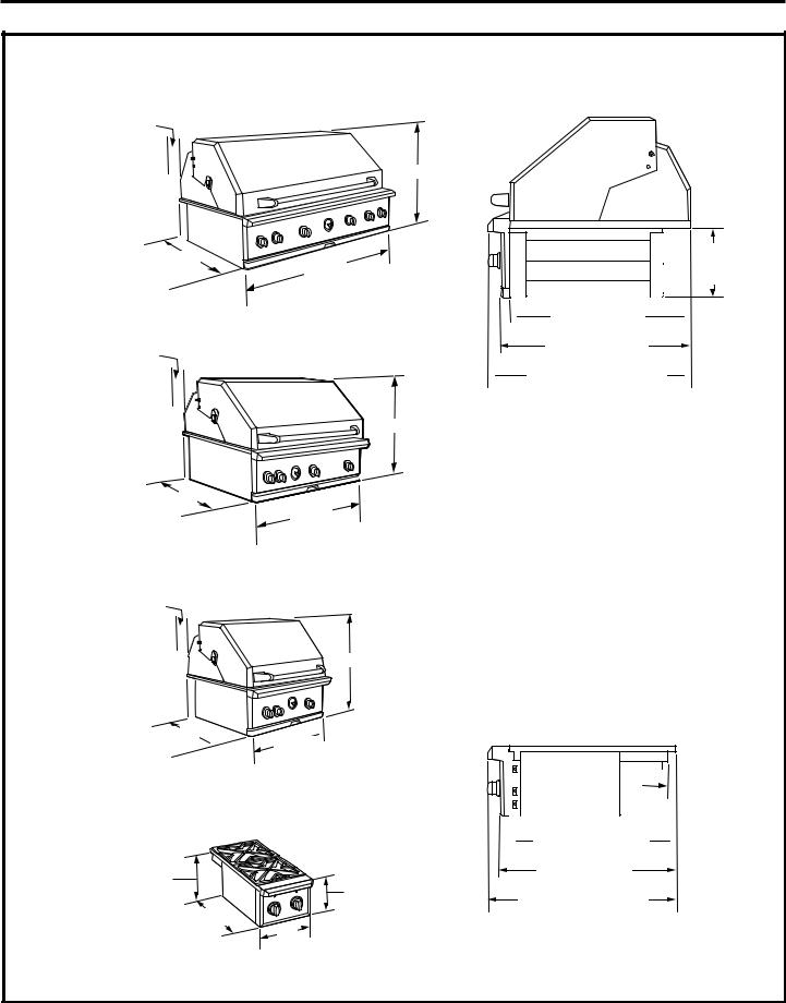
PRODUCT DIMENSIONS AND CLEARANCES
54" Built-In**
12" Min. to Combustibles 4" Min. Clearance for Lid to Non-Combustibles
26"
27"
53-7/8"
42" Built-In**
12" Min. to Combustibles 4" Min. Clearance for Lid to Non-Combustibles
26"
Side View, All Built-In Grill Models
10-1/4" from Bottom of Support Flange
*25-1/2"  Countertop Depth
27" to Front of Control Panel
 28-1/2" to Front of Bullnose
*The weight of the grill is fully supported by the side trims. The back of the grill overlaps the back edge of the cutout.
27"
41-7/8"
30" Built-In**
12" Min. to Combustibles 4" Min. Clearance for Lid to Non-Combustibles
26"
27" 
 29-7/8"
12" Outdoor Cooktop with 2 Burners**
12" Min. to |
|
|
Combustibles |
10-1/2" to |
|
on All Sides |
|
|
the Bottom |
|
|
|
of the Side |
|
|
Support Flange |
11" |
|
|
26-1/2" |
|
|
13" |
**Built-In Monogram Outdoor Grills and Cooktops must be installed into a non-combustible enclosure.
Side View, Built-In Cooktop Model
 7/8" Overlap
at the Back
 *25" Countertop Depth
26-1/2" to Front of Control Panel
28" to Front of Bullnose
*The weight of the cooktop is fully supported by the side trims. The back of the cooktop overlaps the back edge of the cutout.
5
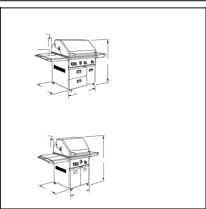
Design Information
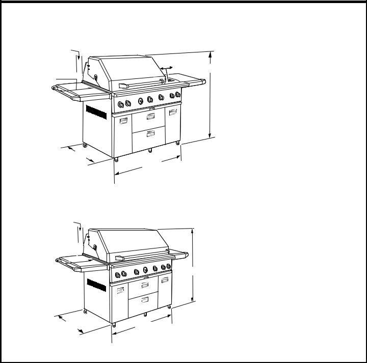
PRODUCT DIMENSIONS AND CLEARANCES
54" Cart with Side Burners
12" Min. to Combustibles 4" Min. Clearance for Lid
to Non-Combustibles
*12" Side Burner
51"
15-1/2" (both sides)
*27-1/2" Side Burner and Shelf
27"
53-7/8"
54" Cart
12" Min. to Combustibles 4" Min. Clearance for Lid to Non-Combustibles
15-1/2" (both sides) 
51"
27" |
53-7/8" |
6
Design Information
PRODUCT DIMENSIONS AND CLEARANCES
42" Cart
12" Min. to Combustibles 4" Min. Clearance for Lid to Non-Combustibles
15-1/2" (both sides)
51" |
27" 
 41-7/8"
30" Cart
12" Min. to Combustibles 4" Min. Clearance for Lid to Non-Combustibles
15-1/2" (both sides) 
51"
27"
29-7/8"
7

Design Information
ACCESSORIES
|
|
|
|
|
|
|
|
|
|
|
|
|
|
|
|
|
|
|
|
|
|
|
|
|
|
|
|
|
|
|
|
|
|
|
|
|
|
|
|
|
|
|
|
|
|
|
|
|
|
|
|
|
|
|
|
|
|
|
|
|
|
|
|
|
|
|
|
|
|
|
|
|
|
|
|
|
|
|
|
|
|
|
|
|
|
|
|
|
|
|
|
|
|
|
|
|
|
|
|
|
|
|
|
|
|
|
|
|
|
|
|
|
|
|
|
|
|
|
|
|
|
|
|
|
|
|
|
|
|
|
|
|
|
|
|
|
|
|
|
|
|
|
|
|
|
|
|
|
|
|
|
|
|
|
|
|
|
|
|
|
|
|
|
|
|
|
|
|
|
|
|
|
|
|
|
|
|
|
|
|
|
|
|
|
|
|
|
|
|
|
|
|
|
|
|
|
|
|
|
|
|
|
|
|
|
|
|
|
|
|
|
|
|
|
|
|
|
|
|
|
|
|
|
|
|
|
|
|
|
|
|
|
|
|
|
|
|
|
|
|
|
|
|
|
|
|
|
|
|
|
|
|
|
|
|
|
|
|
|
|
|
|
|
|
|
|
|
|
|
|
|
|
|
|
|
|
|
|
|
|
|
|
|
|
|
|
|
|
|
|
|
|
|
|
|
|
|
|
|
|
|
|
|
|
|
|
|
|
|
|
|
|
|
|
|
|
|
|
|
|
|
|
|
|
|
|
|
|
|
|
|
|
|
|
|
|
|
|
|
|
|
|
|
|
|
|
|
|
|
|
|
|
|
|
|
|
|
|
|
|
|
|
|
|
|
|
|
|
|
|
|
|
|
|
|
|
|
|
|
|
|
|
|
|
|
|
|
|
|
|
|
|
|
|
|
|
|
|
|
|
|
|
|
|
|
|
|
|
|
ZX27AD, 27" Access Doors |
|
|
|
|
|
|
|
|
|
|
|
||||||||||||||||||
ZX18DS, 18" 2-Drawer Storage |
|
|
|
ZX18TC, 18" Trash Bin |
|||||||||||||||||||||||||||||||||||
|
|
|
|
|
|
|
|
|
|
|
|
|
|
|
|
|
|
|
|
|
|
|
|
|
|
|
|
|
|
|
|
|
|
|
|
|
|
|
|
|
|
|
|
|
|
|
|
|
|
|
|
|
|
|
|
|
|
|
|
|
|
|
|
|
|
|
|
|
|
|
|
|
|
|
|
|
|
|
|
ACCESSORY PRODUCT DIMENSIONS
22-5/8" |
26" |
20" |
18-1/8" |
18" |
27" |
|
|
8
Installation Preparation
ADVANCE PLANNING
Built-In Monogram Outdoor Grills and Cooktops are designed for easy installation into a non-combustible enclosure. The grill drops into the opening and hangs from its side flanges.
•A deck is not required for support from the bottom.
•The counter surface and edges must be flat and level.
•The installation structure within 12" of the product must be constructed completely of non-combustible materials.
NOTE:Non-combustible materials are materials which are not capable of being ignited and burned, such as steel, iron, brick, concrete, granite or slate.
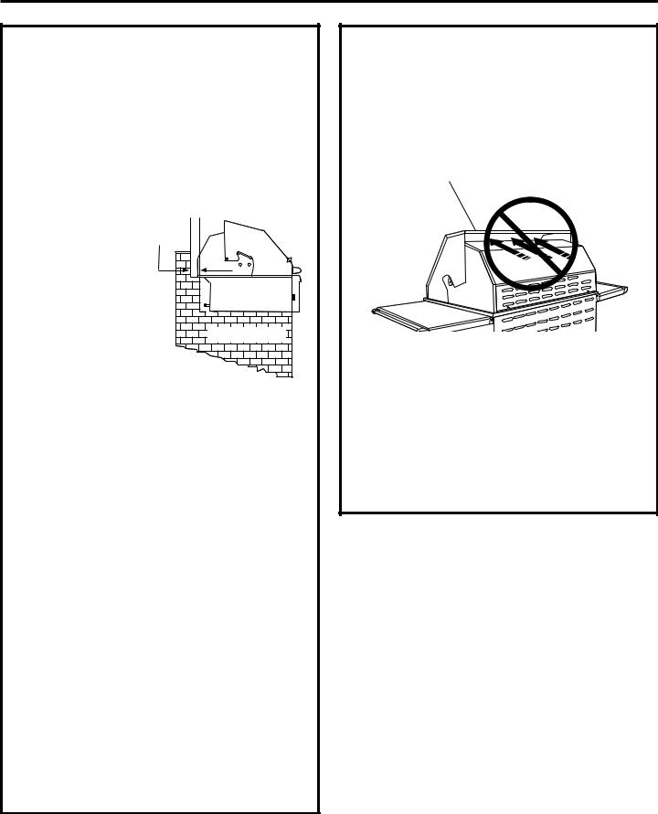
Clearances: |
4" Min. |
• A 4" minimum |
Lid Clearance |
|
|
clearance is required |
|
behind the grill to |
|
allow the hood to |
|
open. |
|
|
Non-Combustible |
ClearancestoWoodorOtherCombustibleMaterials:
•Allow at least a 12" clearance at the back of the grill when the exhaust is directed to a window or a surface that is difficult to clean.
•Allow 12" minimum clearance on both sides and the back of the grill to adjacent vertical combustible construction.
•Do not install this outdoor grill or cooktop under overhead combustible construction.
Accessories:
•ZX27AD Access Doors may be installed directly below a grill.
•ZX18DS Storage Drawers CANNOT be installed directly below a grill or cooktop.
•ZX18TC Trash Bin CANNOT be installed directly below a grill or cooktop.
Security:
Cart models are equipped with an anti-theft, stationarymount security loop. This loop allows you to secure the grill to a structure. See page 19.
CooktopInstallation:
Both an LP or Natural gas cooktop can be installed in combination with a grill. The cooktop can be connected to the same LP tank as the grill.
•The cooktop can also be installed alone and be supplied by a separate LP tank. In this case, you must order a regulator hose assembly. Order WB21X10156 regulator hose assembly for a 20-lb. LP tank connection.
CHOOSING THE LOCATION
•These outdoor grills are designed for outdoor use only. Do not locate the grill in a building, garage or other enclosed or semi-enclosed area.
•Ensure that fresh air ventilation is adequate.
NEVER USE THE GRILL IN WINDY CONDITIONS. Wind hitting the grill while in use, especially winds blowing into or across this hood gap, can cause poor performance and in some cases can cause the control panel to get hot enough to cause burns.
Steady or gusty winds can prevent the normal exhaust of hot gases. Locate your grill away from prevailing winds and avoid grilling in windy conditions.
•Locate the grill where prevailing winds will blow into the front of the control panel.
•The minimum clearances to wood or other combustibles must be maintained at all times.
•Do not install an outdoor grill or cooktop under overhead combustible construction.
•The location must be level and stable.
9
Installation Preparation
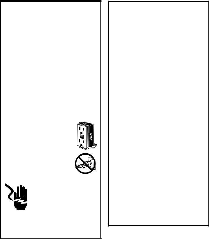
ELECTRICAL SUPPLY REQUIREMENTS
A 120-volt, 60Hz, 15-amp power supply is required. An individual properly grounded branch circuit or circuit breaker is recommended. Install a properly grounded 3-prong electrical receptacle at the rear and below the cutout. Electrical must be located within reach of the 6-ft. power cord.
GROUNDING THE OUTDOOR COOKING CENTER AND 2-BURNER COOKTOP
IMPORTANT: PLEASE READ CAREFULLY. FOR PERSONAL SAFETY, THIS APPLIANCE MUST BE PROPERLY GROUNDED.
The power cord of this appliance is equipped with a 3-prong (grounding) plug which mates with a standard 3-prong (grounding) wall receptacle to minimize the possibility of electric shock hazard from this appliance. Have the wall outlet and circuit checked by a qualified electrician to make sure the outlet is properly grounded. Where a standard 2-prong wall outlet is encountered, it is your personal responsibility and obligation to have it replaced with a properly grounded 3-prong wall outlet.
• DO NOT, UNDER ANY CIRCUMSTANCES, CUT OR REMOVE THE THIRD (GROUND) PRONG FROM THE POWER CORD.
• DO NOT USE AN ADAPTER PLUG TO CONNECT THE OUTDOOR COOKING CENTER TO A 2-PRONG OUTLET.
•DO NOT USE AN EXTENSION CORD WITH THIS APPLIANCE.
• DO NOT PLACE THE UNIT IN STANDING WATER OR ALLOW THE POWER CORD TO BE IMMERSED.
THIS PRODUCT IS RECOMMENDED TO BE CONNECTED TO A POWER SOURCE WITH GROUND FAULT
CIRCUIT INTERRUPT (GFCI) PROTECTION WHEN INSTALLED IN AN OUTDOOR LOCATION. FOLLOW LOCAL CODES.
If you are uncertain about the GFCI protection on the power source to which you are connecting this appliance, please contact a professional electrician for verification.
GAS SUPPLY REQUIREMENTS
These grills are factory-set for either LP or natural gas operation.
Do not attempt to operate the cooking center on a different gas type than for what the grill orifices and regulator are set. Check the rating plate to be sure the gas supply matches the cooking product. Fuel type conversion requires a conversion kit. Contact your dealer or call 1.800.626.2002 to order.
GAS TYPE CONNECTIONS
AND CONVERSIONS
•WB28X10116 – LP to Natural Gas Operation Conversion Kit. This kit is for all grill models and 2-burner cooktops. Order this kit from your Monogram supplier.
•WB28X10117 – Natural to LP Gas Operation Conversion Kit. This kit is for all grill models and 2-burner cooktops. Order this kit from your Monogram supplier.
•WB28X10118 – LP Portable/Stationary Conversion Kit. To change the connection from LP portable (20# tank) to whole house stationary tank or stationary tank to portable. Order this kit from your Monogram supplier.
•WB28X10119 – High Altitude Conversion Kit. For operation above 2,000 feet. Order this kit from your Monogram supplier.
COOKTOP AND OUTDOOR COOKING CENTER COMBINATION INSTALLATION
•Natural gas models are designed to operate at 4" water column pressure. For proper operation, the pressure of the natural gas supplied to the regulator must be between 5" and 14" water column.
•LP models are designed to operate at 11" water column pressure. For proper operation, the pressure of the LP gas supplied to the regulator must be between 12" and 14" water column.
•Install a manual shut-off valve in the gas line (not provided), in an easily accessible location. Make sure the homeowner knows where and how to shut off the gas supply to the grills.
10
Installation Preparation
OUTDOOR GRILL, COOKTOP AND ACCESSORY CUTOUT DIMENSIONS
|
|
12" Min. |
|
|
|
|
|
Separation |
|
|
|
28-3/4" for 30" Models |
|
Between Cutouts |
|
|
|
40-3/4" for 42" Models |
|
|
|
|
|
52-3/4" for 54" Models |
|
|
|
|
|
|
|
|
|
|
|
|
|
|
|
|
|
|
|
|
11-7/8" |
||
|
|
|
|
|
|
|
|
|
|
|
|
|
|
|
Gas and Electrical Locations |
|
|
||
|
|
|
24-1/2" |
|
|
|
|
|
24-1/2" |
|
Outdoor |
|
|
|
24" |
|
|
Cooktop |
|
|
Trash Bin |
||
|
|
|
|
|
|||
|
|
|
ZGU122 |
10-7/8" |
|
ZX18TC |
|
|
|
Grill Cutout |
|
|
2-Drawer |
|
|
|
|
|
|
Storage |
|
|
|
|
|
|
|
|
|
|
|
|
|
|
Non-Combustible |
18-9/16" |
ZX18DS |
|
|
|
|
|
|
|
|
||
|
1-1/8" |
Access Doors |
18-1/4" |
|
|
|
16" |
36" |
ZX27AD |
*See Note. |
|
|
|
|
|
Min. |
|
|
|
17-1/4" |
|
||
Min. |
|
|
|
|
|
||
|
|
|
|
|
|
||
|
|
|
|
|
|
2-1/4" min. |
|
24-1/8" *Note: When installing more than one accessory below the countertop, align the accessories across the bottom by adjusting the dimension above the floor. The cutouts must be offset depending on the product overlap below the cutout. Overlap for ZX27AD is 7/8", for ZX18DS is 1-1/4" and for ZX18TC is 1-3/16".
Gas and Electrical Locations |
|
|
|
|
10" Min. |
|
GAS LOCATION: |
3-1/2" |
|
Cut a 3-1/2" dia. hole for |
|
|
|
||
|
3-1/2" |
|
the manifold connection |
|
|
as shown for LP tank |
|
|
7-3/8" |
|
or stationary gas line |
|
|
|
connections. |
|
|
|
ELECTRICAL LOCATION: |
|
|
2" |
Cut a 1" dia. hole |
|
|
at the back left side |
|
|
|
|
|
|
|
|
of the cutout. |
3-1/2" Dia. Hole |
|
3-1/2" Dia. Hole |
for Stationary |
|
for LP Tank Hose |
Gas Line |
|
|
|
|
|
|
|
|
•If the countertop has an overhang, it must be notched or cut back flush with the front face of the cabinet below. This will allow the grill or side burner to fit flush at the front.
Countertop Notch Detail
to Depth
Face Cabinet
5/8" for Grills
9/16" for Outdoor Cooktop
•The grill and outdoor cooktop drops into the opening and hangs from the side flanges. A deck is not required for support on the bottom.
•The construction must be level and stable and capable of supporting up to 400 lbs.
•The opening for the cooktop must be 24-1/2" deep from the front of the countertop. Cut a 1" dia. hole below the cooktop for the drain hose.
•Cut a 1" dia. hole at the back left side of the cutout for the grill’s electrical connection.
•A 120 volt outlet must be located within reach of the grill’s
6' power cord. The transformer bracket must be mounted within 3-1/2 feet of the outdoor grill.
•Maintain 12" separation between cutouts for an outdoor grill and an outdoor cooktop installation.
Rotisserie |
Connection |
Non-Combustible |
The grill rotisserie connection is on the left side near the front. Installation into a 24-1/2" front-to-back opening allows access to the rotisserie outlet.
11
Installation Preparation
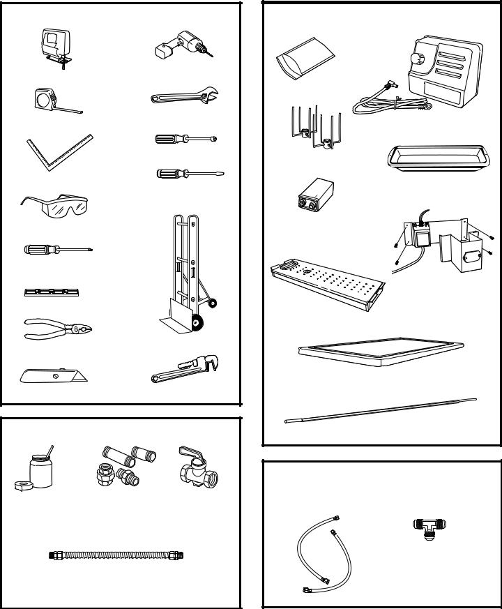
TOOLS REQUIRED
Saber Saw
Measuring Tape
Carpenter’s Square
Safety Glasses
Phillips #2 Screwdriver
Level
Pliers
Utility Knife
Drill and
Appropriate Bits
Adjustable Wrench
1/4" Driver or Wrench
Flat-Blade Screwdriver
(3/32" blade)
Appliance Dolly
Pipe Wrench
MATERIALS REQUIRED (not provided)
|
|
|
|
|
|
|
|
|
|
|
Pipe Joint Sealant |
|
|
|
|
|
|
||||
|
|
Manual Shut-Off |
||||||||
Pipe Fittings |
||||||||||
(approved type and |
|
|
|
|
Valve |
|||||
|
resistant to LP or |
|
|
|
|
|
|
|||
|
natural gas) |
|
|
|
|
|
|
|||
|
|
|
|
|
|
|
|
|
|
|
|
|
|
|
|
|
|
|
|
|
|
Use stainless steel or flexible metal gas line to reach the built-in installation location or cart model location (if natural or whole-house LP). Do not use vinyl hose.
PARTS PROVIDED
Grill Cover
Rotisserie Spit Forks
9V Battery (installed
on some models)
Smoker Box (on some models)
Cutting Board (on some models)
Rotisserie Motor and Connector
Drip Pan
Bracket with Transformer and Battery Compartment (only on built-in models)
Rotisserie Spit Rod
ZGU122 COOKTOP PARTS
LP MODELS
See product to determine parts used.
3/8" Flare Tee and Two 3/8" x 3/8" Flare Hoses (on models so equipped)
12

Installation Preparation
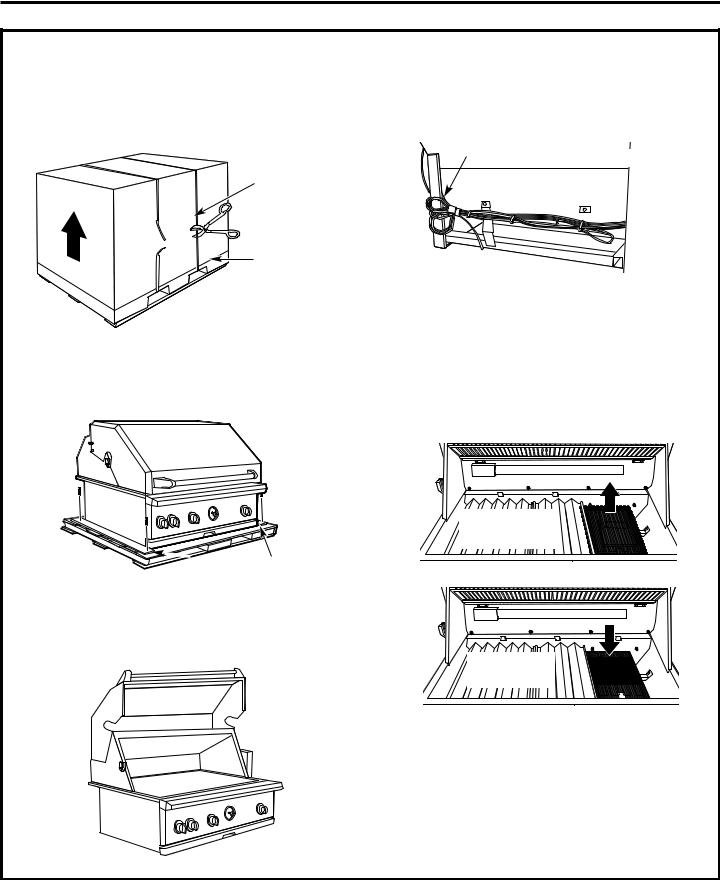
REMOVE PACKAGING FROM CART MODELS
1.Cut the banding. Use a box cutter or utility knife to score and cut the carton along the base (or remove the staples with a staple remover or a screwdriver).
2.Lift the carton straight up and off of the grill.
6. Open the lid. Cut plastic ties and bands.
Cut the banding with tin snips.
Score and cut.
3. Remove all outside packing materials.
7. The right-side shelf must be removed when using an appliance dolly to lift the grill off the skid.
A. On the right side of the grill, remove the screw from the back side of the shelf.
Parts
Package
Grill Grates
Parts
Package
4.Remove the parts packages on each side at the bottom.
5.Remove the screws from the hold-down board on the right side of the skid to allow the appliance dolly to
slip under the wheels.
NOTE: When using an appliance dolly, the grill must be handled and removed from the right side. The rightside wheels do not rotate.
Hold-Down
Board
B.Slide the shelf out of the holding pin at the front end of the bracket.
Holding Pin 

13

Installation Preparation
REMOVE PACKAGING FROM CART MODELS (cont.)
8.Position the blade of the dolly next to the right side of the grill. Tilt the grill back and away to allow blade to slip under the wheels.
NOTE: The wheels must rest on the blade of the appliance dolly.
Secure the appliance dolly belt around the
grill above or below the controls to avoid damage to the knobs.
9.Tilt and lift with the appliance dolly to remove the skid from below the grill.
10.Roll the grill into operating position. Reinstall the shelf on the right side.
11.Remove the tie holding the sear burner (on some models). Lift the wire mesh cover on the sear burner and remove packaging. Carefully, replace the wire mesh cover. The wire mesh must be wrapped around the vertical side flanges.
Wheels must be  positioned ON the
blade of the appliance dolly.
Lift wire mesh and remove packaging.
Replace wire mesh cover.
14
Installation Preparation
REMOVE PACKAGING FROM BUILT-IN MODELS
1.Cut the banding. Use a box cutter or utility knife
to score and cut the carton along the base (or remove the staples with a staple remover or a screwdriver).
2.Lift the carton straight up and off of the grill.
Cut the banding with tin snips.
Score and cut.
3.Remove all outside packing materials.
4.Remove the screws from the hold-down boards on the skid. This will allow better access to the ends when lifting the grill off the skid.
6.Close the lid. Cut the plastic tie holding the wires against the left side. Let the battery and transformer wires hang loose along the back side.
Cut tie on the rear vertical support.
7.Lift the grill off the skid and slide it into the prepared countertop opening.
8.Remove the tie holding the sear burner (on some models). Lift the wire mesh cover on the sear burner and remove packaging. Carefully, replace the wire mesh cover. The wire mesh must be wrapped around the vertical side flanges of the burner.
Lift wire mesh and
remove packaging.
 Hold-Down
Boards
5. Open the lid. Cut plastic ties and bands. Remove the parts package. Remove the grill grates and packaging.
Replace wire mesh cover.
15

Installation
LP TANK TIE-DOWN (for built-in island installations)
Outdoor cooking applicances require an integral means of limiting the movement of the LP gas cylinder. For built-in appliances which require the use of a remote LP gas supply cylinder (island applications), a retaining device must be created.
Lateral movement shall not exceed 1" (25.4 mm) at the retention means. The cylinder, or any portion of, shall not become dislodged from the retention device when a lateral force of equal weight to the cylinder is applied, from any direction, at the center of the vertical height of the cylinder.
Retaining device must not interfere with the operation of the cylinder valve, and no movement shall transmit strain to rigid tubing or pipe/hose connections. Hose must not touch any portion of the grill/appliance. (ANSI Z21 58z 2006/CGA 1.6z 2006)
LP tank is inserted into frame. LP tank is secured with fixed thumbscrew on three sides.
8-1/4" 8-1/4"
1" Min.
Tee Nut 1/4-20
Recommended
(3 Sides of Frame)
Thumbscrew 1/4-20 right angle or spaded 2" long (3 required)
TANK DRAWER WITH LP TANK RETAINER LOOP (free-standing models only)
To install the LP tank, fully extend the tank drawer and the lift retainer loop. Place the tank on the drawer bottom, inserting the loop on the bottom of the tank through the hole in the drawer bottom. Tilt the tank forward to lower the retainer loop to engage the top ring on the tank. Insert the coupler sleeve on the regulator over the tank inlet; turn clockwise to tighten. Do not overtighten the coupler. Open the tank valve when ready to use the grill. Always close the tank valve when cooking is complete.
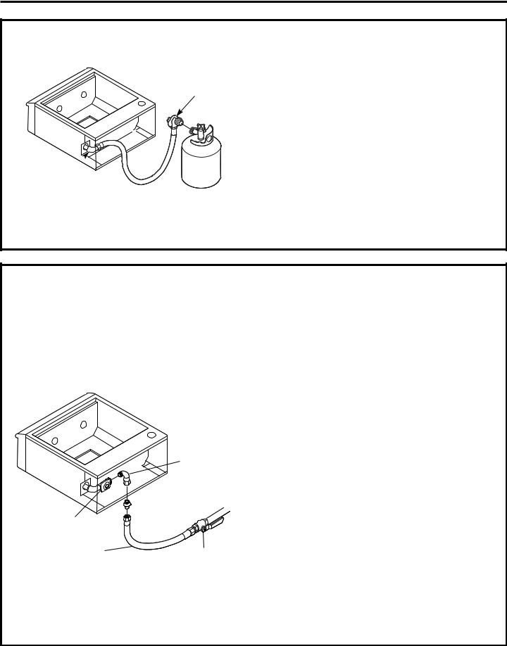
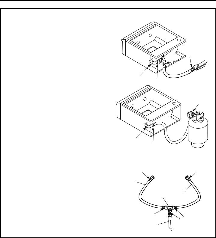
LP GAS GRILL CONNECTIONS TO A GRILL OR COOKTOP
LP Gas Cooktop and Grill Combination Connections
Use this method to connect a single tank to both appliances.
To Manifold
of Grill
3/8" Flare Tee
From Regulated
LP Tank
To Cooktop
Note: The supplied hoses are different lengths. Connect them to suit your installation situation.
LP gas connections
•Completely close the main valve on the LP tank supplying the grill.
•Attach one hose to the cooktop gas inlet; tighten.
•Attach one hose to the grill gas inlet; tighten.
•Attach the hose ends from the grill and cooktop to the ends of the supplied 3/8” flare tee as shown.
•Attach the supplied regulator hose assembly to the 3/8” flare tee as shown.
16
Installation Instructions
LP GAS GRILL CONNECTIONS TO A GRILL OR COOKTOP (cont.)
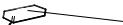
Single Gas Cooktop or Grill Connection
LP Hose and
Regulator
3/8” Flare 
Fitting
20-lb. Type 1 LP Tank 

Built-in models shown.
For models installed on carts, open the tank storage drawer on the right side to make the tank connection.
Outdoor Cooktop: Install the cooktop with a separate tank using the same method. Order WB21X10156 Regulator hose assembly for the 20-lb. tank connection.
To connect 20-lb. LP tank:
•Attach the regular hose assembly to the brass elbow. Do not use threading compound.
•Insert the coupler sleeve on the regulator over the tank inlet; turn clockwise to tighten. Do not overtighten the coupler.
To disconnect from the 20-lb. LP tank:
•Turn tank valve to OFF.
•Grasp the coupler sleeve, turn counterclockwise and remove.
NATURAL GAS GRILL CONNECTIONS
•The gas supply line must be sized to accommodate the outdoor grill and, if present, an outdoor cooktop connected to the same gas supply.
•The grill or cooktop and its individual shut-off valve must be disconnected from the gas supply during any pressure testing of the system at test pressures in excess of 1/2 PSIG.
Regulator
3/4" Min. Dia.
Flexible Connector
Built-in models shown.
1/2" Male to 3/4" Female Elbow
Incoming Natural
Gas Supply Pipe
 3/4" NPT to
3/4" Flare Fitting
Manual Shut-Off
Valve
Make connection for models installed on carts in the same manner. The entry for the gas line is on the back of the cart.
Outdoor Cooktop: Install the cooktop using the same method illustrated above for the outdoor grills.
The installation of the outdoor grills or cooktop must conform with local codes or, in the absence of local codes, with the National Fuel Gas Code, ANSI Z223.1, latest edition.
Operating pressure is 4" water column. Supply pressure should be 5" to 14" water column. If pressure is more than 14" water column, a step-down regulator is required.
Check with the local gas utility or with local codes for instructions on installing gas supply lines. Be sure to check on type and size of run and how deep to bury the line. If the gas line is too small, the grill will not function properly.
•Install a manual gas shut-off valve in an easily accessible location.
•Use threading compound on male threads only. Do not use threading compound on the male end of a flare adapter.
•Make connections as shown.
•Check to be sure the regulator arrow points in the direction of gas flow, towards the grill and away from the gas supply.
17
Installation
 WARNING:
TEST FOR LEAKS
A complete gas tightness check must be performed at the installation site.
 CAUTION:
To prevent fire or explosion hazard, DO NOT use or permit sources of ignition in the area while performing a leak test. Perform leak test outdoors only. Never perform a leak test with fire or flame. DO NOT SMOKE WHILE PERFORMING THE LEAK TEST.
•Use an approved non-corrosive leak detection solution or create a soapy solution of equal parts mild dishwashing detergent and water.
•Check to be sure all controls are in the OFF position.
•Turn on the fuel supply. For natural gas, turn manual shut-off valve handle 1/4 turn to align with gas flow. For LP, turn cylinder valve knob counterclockwise one full rotation.
•Apply liquid leak detector generously on all connections and fittings. See illustrations.
•If growing bubbles appear on any connection point, IMMEDIATELY turn off the gas supply.
To stop a gas leak:
•Turn off the fuel supply.
•Turn on control knobs to release pressure. Turn controls OFF.
•Wash off soapy solution and towel dry.
•Tighten the loose joint and perform a new leak test.
Natural Gas Leak
Test Points
LP Gas Leak
Test Points
LP Gas Leak Test Points
With Cooktop
To Manifold
of Grill
3/8" |
To Cooktop |
Flare Tee |
|
From Regulated
LP Tank
18
Installation Instructions
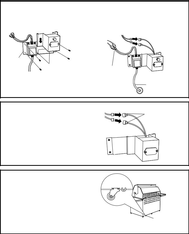
INSTALL BRACKET WITH TRANSFORMER (Built-In Models Only)
•Mount the bracket to the back wall of the enclosure with 4 screws (not supplied).
•Slide the battery compartment from the top, straight down, engaging the side slots.

 Battery/Fuse
Compartment
Bracket
Side Slots
NOTE:All connectors are polarized to connect correctly.
•Join transformer connectors.
•Join battery connectors.
•Route the power cord through the enclosure to the electrical outlet.
 Battery Connectors
Transformer
Connectors
Power Cord
INSTALL COOKTOP BRACKET WITH BATTERY COMPARTMENT
•Mount the bracket to the back wall of the enclosure with 4 screws (not supplied).
•Slide the battery compartment from the top, straight down, engaging the side slots. (If necessary, the bracket may be factoryassembled.)
•Join battery connectors.
Battery Connectors
SECURITY LOOP
A stainless steel loop is welded to the bottom of the free-standing grill chassis near the back right wheel. To secure the grill, put a chain through the steel loop and padlock through a stationary, secured eyelet (chain, padlock and eyelet not provided).
Loop for securing free-standing grill with a chain (located on grill chassis bottom near the back right wheel)
19
Installation
Instructions
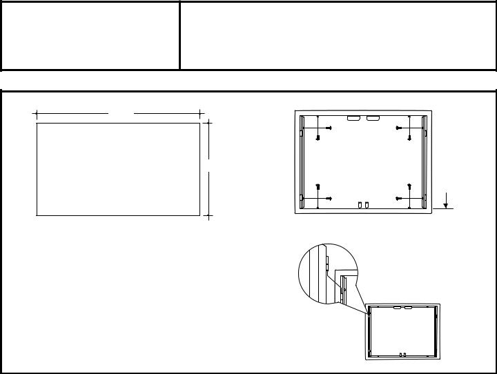
ZX27AD ACCESS DOORS
24-1/8"
Double Accessss |
18-1/4" |
Doors |
7/8"
 Overlap
• Cut the opening to the dimensions shown. Reinforce the inside of the opening using at least 1" wide material surround to accept the frame-mounting
screws.
• Place the frame into the opening and secure with
screws (provided) on all sides as shown.
• Hang the doors on the hinges as shown.
NOTE: If you are installing another accessory into the same enclosure, measure and cut the openings to accommodate the bottom overlaps and align them evenly across the bottom.
20
Installation
Instructions
ZX18DS STORAGE DRAWER
2-Drawer
18-9/16" Storage ZX18DS
 17-1/4"
17"
18-3/16"
10-1/8" |
24-1/8" |
|
25-3/16" |
18"
1-1/4" Drawer
Overlap
2 Mounting 
Screws
1-1/4" Drawer 
Overlap
IMPORTANT: The supplied rear support bracket adjusts from 4-1/8" to 6-7/8". When using the supplied bracket, cut the opening at least 4-1/8" above the floor. If the opening is closer to the floor of the enclosure, use another means of support for the back of the drawer.
The rear support must be capable of supporting 50 lbs., plus load.
•Cut the opening to the dimensions shown. Reinforce the inside of the opening using at least 1" wide material surround to accept the frame-mounting screws.
NOTE: If you are installing another accessory into the same enclosure, measure and cut the openings to accommodate the bottom overlaps and align them evenly across the bottom.
•Adjust the bracket height with screws (provided) so that the drawer cabinet will be level with the cutout.
•Slide the drawers into the opening.
•Open the top drawer. Locate the screw holes in the top of the drawer cabinet, just inside the drawer. Install 2 screws (not provided) to secure the drawer to the enclosure.
Rear Support Bracket
Side View
4-1/8" to
6-7/8"
21
Loading...