


GXRM10RBL
Table of contents
 Loading...
GEAppliances.com
Reverse Osmosis
215C1219P004 49-50237 07-09 JR
Filtration System
GXRM10RBL
Owner’s Manual
and Installation
Safety Instructions
Safety Instructions . . . . . . . . . . . . . . . . . .2
Specification Guidelines . . . . . . . . . . . . .3
Installation Instructions
Before Beginning Installation . . . . . . . .4
Faucet Drain Tubing and
Water Supply Tubing . . . . . . . . . . . . . . . .8
Faucet Installation . . . . . . . . . . . . . . . . . .7
Filtration Drain Connection . . . . . . . . . .8
System Assembly . . . . . . . . . . . . . . . . . . .9
Things to Check
Before Installation . . . . . . . . . . . . . . . . . . .5
Tools and Materials Required . . . . . . . .4
Water Supply . . . . . . . . . . . . . . . . . . . . . . .6
Care and Cleaning
Prefilter, Postfilter and
RO Cartridge Replacement . . . . .10, 11
Sanitization . . . . . . . . . . . . . . . . . . . . . . . .10
Water Test Kit . . . . . . . . . . . . . . . . . . . . .12
Operating Instructions
About the RO System . . . . . . . . . . .13, 14
Troubleshooting Tips . . . . . . . . . .15
Consumer Support
Consumer Support . . . . . . . .Back Cover
Parts List/Catalog . . . . . . . . . . . . . .16, 17
Warranty . . . . . . . . . . . . . . . . . . . . . . . . . .20
Manuel d’utilisation
et d’installation
Manual del propietario
y instalación
La section française commence à la page 21
Osmose Inversée
Système de Filtration
La sección en español empieza en la página 41
Ósmosis Inversa
Sistema de Filtración
GXRM10RBL is Tested and
Certified by NSF International
against NSF/ANSI Standard 58
and CSA B483.1 for reduction
of the claims specified on the
Performance Data Sheet.
Write the model and serial
numbers here:
Model # __________________
Serial # __________________
You can find them on the bracket.
C U.S.
IMPORTANT SAFETY INFORMATION.
READ ALL INSTRUCTIONS BEFORE USING.
■ Check with your state and local public works
department for plumbing and sanitation codes.
You must follow these guidelines as you install the
Reverse Osmosis system. Using a qualified installer
is recommended.
■ If house water pressure is over the maximum
(125 pounds per square inch), install a pressure
reducing valve in the water supply line to the Reverse
Osmosis system.
■
Be sure the water supply conforms with the
Specification Guidelines. If the water supply conditions
are unknown, contact your municipal water company
or your local health department for a list of
contaminants in your area and a list of laboratories
certified by your state to analyze drinking water.
WARNING: Before using the Reverse
Osmosis system for the first time, the system must be
purged. The Reverse Osmosis cartridge contains
a food grade preservative that must be purged
from the system. The preservative will give product
water an unpleasant taste and odor.
■ This product reduces fluoride in drinking water.
Please consult your dentist if you have questions.
WARNING: Do not use with water that is
microbiologically unsafe or of unknown quality
without adequate disinfection before the system.
Systems certified for cyst reduction may be used on
disinfected water that may contain filterable cysts.
This system has been tested for the treatment of
water containing pentavalent arsenic (also known
as As(V), As(+5) or arsenate) at concentrations of 0.050
mg/L or less. This system reduces pentavalent
arsenic, but may not reduce other forms of arsenic.
This system is to be used on water supplies
containing a detectable free chlorine residual or
on water supplies that have been demonstrated
to contain only pentavalent arsenic. Treatment
with chloramine (combined chlorine) is not sufficient
to ensure complete conversion of trivalent arsenic
to pentavalent arsenic. Please see the Arsenic Facts
section of the Performance Data Sheet for further
information.
This Reverse Osmosis system contains a replaceable
treatment membrane cartridge critical for effective
reduction of Total Dissolved Solids. The water should
be tested periodically to verify that the system is
performing satisfactorily. See the About the Water Test
Kit section. This system is acceptable for treatment of
influent concentrations of no more than 27 mg/L
nitrate and 3 mg/L nitrite in combination measured as
N and is certified for nitrate/nitrite reduction only for
water supplies with a pressure of 280kPa (40 psig)
or greater.
SAVE THESE INSTRUCTIONS
READ AND FOLLOW THIS SAFETY INFORMATION CAREFULLY.
■ Install or store where it will not be exposed to
temperatures below freezing or exposed to any type
of weather. Water freezing in the system will damage
it. Do not attempt to treat water over 100°F.
■ Do not install on HOT WATER. The temperature
of the water supply to the Reverse Osmosis system
must be between the minimum of 40°F and the
maximum of 100°F. See the Specification Guidelines.
■ Extended non-use of the Reverse Osmosis system.
If the system has not been used for one week or
more, open the RO water faucet and allow the
system to drain. Close the RO water faucet and
allow the system to regenerate the water supply.
■ Recommended installation is under the sink. However,
the unit can be installed in a remote location, up to
20 feet away from the sink. Additional installation
materials may be required. If Reverse Osmosis
system is connected to a refrigerator icemaker, a
special icemaker connection kit is required (RVKIT).
Do not use copper tubing for the connection between
the Reverse Osmosis system and the refrigerator.
WARNING: Discard all unused parts and
packaging material after installation. Small parts
remaining after the installation could be a choke
hazard.
■
Sanitize upon installation of the Reverse Osmosis
system and after servicing inner parts, including
replacement of prefilter, postfilter and Reverse
Osmosis cartridge. It is important to have clean hands
while handling inner parts of the system. See the
Sanitization section.
■
This Reverse Osmosis system contains a replaceable
component critical to the efficiency of the system.
Replacement of the Reverse Osmosis component
should be with one of identical specifications, as
defined by the manufacturer, to assure the same
efficiency and contaminant reduction performance.
See Automatic Shutoff Valve section on page 13.
BE SURE TO FOLLOW ALL APPLICABLE STATE
AND LOCAL CODES.
WARNING!
For your safety, the information in this manual must be followed to minimize the risk
of property damage or personal injury.
SAFETY PRECAUTIONS
PROPER INSTALLATION AND MAINTENANCE
This Reverse Osmosis system must be properly installed and located in accordance with the
Installation
Instructions before it is used.
Consumer Support Troubleshooting Tips
Operating Instructions
Safety Instructions
Installation
Instructions
2
Consumer Support
Troubleshooting Tips
Operating InstructionsSafety Instructions
Installation
Instructions
Specification guidelines. GEAppliances.com
The system makes a good supply of drinking water each day.
How much it will make depends primarily on these things…
Product – height 15″ width 14″ depth 5.5″
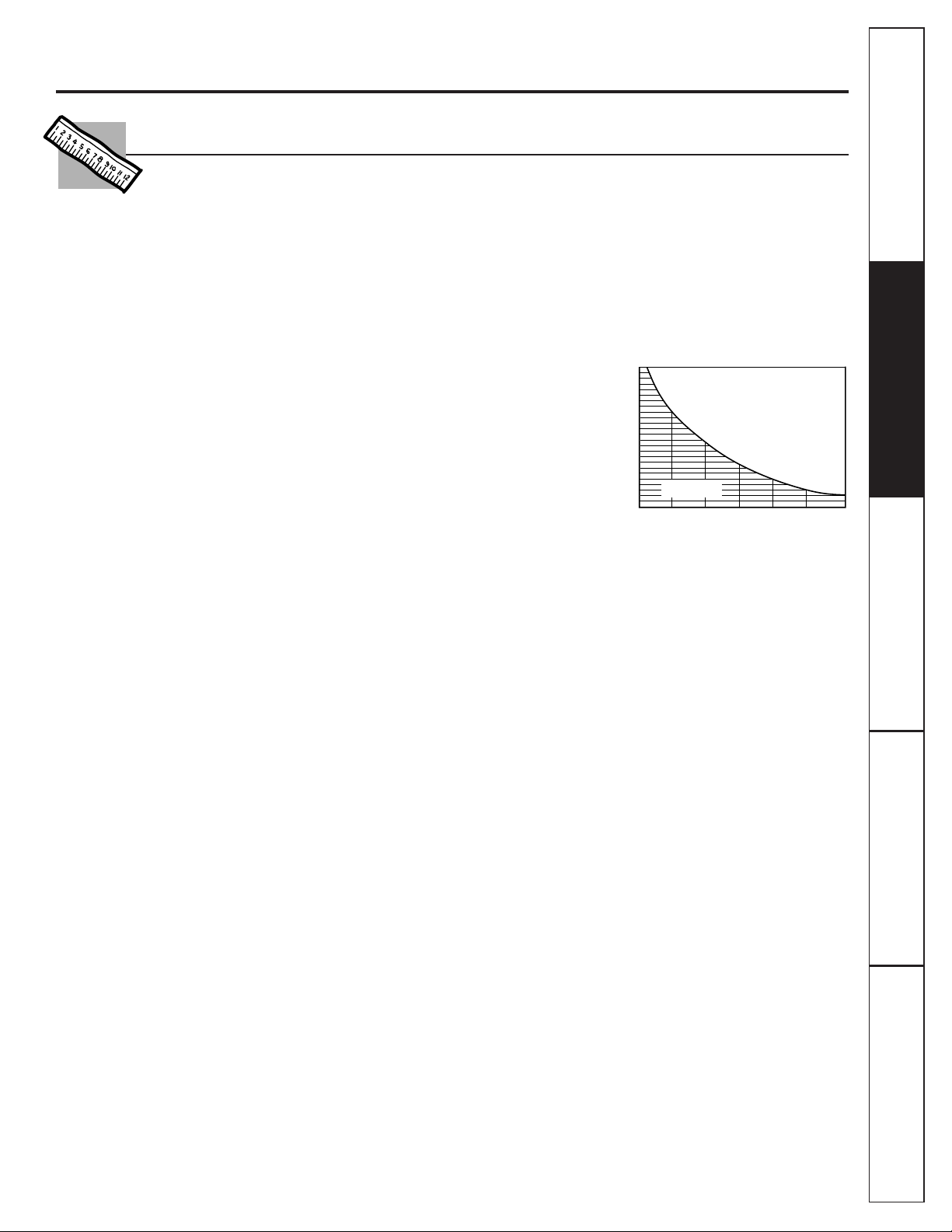
Incoming Water pH
WATER SOFTENER RECOMMENDED
INCOMING WATER HARDNESS (GPG)
60
50
40
30
2010
8
6
7
7.5
6.5
Water Softener
not required
Maximum iron, manganese, hydrogen sulfide (ppm) . . . . . . . . . . . . . . . . . . . .<0.1
Chlorine in water supply . . . . . . . . . . . . . . . . . . . . . . . . . . . . . . . . . . . . . . . . . . . . . . .2.0 ppm maximum allowable
b
Feed water pH limits (pH) . . . . . . . . . . . . . . . . . . . . . . . . . . . . . . . . . . . . . . . . . . . . . . .4–10
Product (quality) water, 24 hours—gallons . . . . . . . . . . . . . . . . . . . . . . . . . . . . . .9.83
a
Percent rejection of TDS (new membrane) . . . . . . . . . . . . . . . . . . . . . . . . . . . . . .92.4%
a
Cyst reduction . . . . . . . . . . . . . . . . . . . . . . . . . . . . . . . . . . . . . . . . . . . . . . . . . . . . . . . . .99.99%
Storage tank capacity—gallons . . . . . . . . . . . . . . . . . . . . . . . . . . . . . . . . . . . . . . . .4
d
Efficiency rating . . . . . . . . . . . . . . . . . . . . . . . . . . . . . . . . . . . . . . . . . . . . . . . . . . . . . . .9.63%
e
Recovery rating . . . . . . . . . . . . . . . . . . . . . . . . . . . . . . . . . . . . . . . . . . . . . . . . . . . . . . . .18.77%
f
Automatic shutoff control . . . . . . . . . . . . . . . . . . . . . . . . . . . . . . . . . . . . . . . . . . . . . .yes
Prefilter and postfilter . . . . . . . . . . . . . . . . . . . . . . . . . . . . . . . . . . . . . . . . . . . . . . . . .(FX12P) Carbon Block
Reverse Osmosis membrane . . . . . . . . . . . . . . . . . . . . . . . . . . . . . . . . . . . . . . . . . . .(FX12M) Thin Film Polyamide
Dimensions (inches) . . . . . . . . . . . . . . . . . . . . . . . . . . . . . . . . . . . . . . . . . . . . . . . . . . . .height 15″ width 14″ depth 5.5″
Feed water pressure limits—pounds per square inch (psi) . . . . . . . . . . . . . . . . . . . . . .40–125
c
Feed water temperature limits—minimum/maximum degrees F . . . . . . . . . . . . . . .40–100
Maximum Total Dissolved Solids (TDS)—parts per million (ppm) . . . . . . . . . . . . . . . .2000
Maximum water hardness at 6.9 pH recommended to optimize membrane
life—grains per gallon (gpg) . . . . . . . . . . . . . . . . . . . . . . . . . . . . . . . . . . . . . . . . . . . . . . . . . . . . . .10
For water with hardness greater than 10 grains (at 6.9 pH), the use of a
softener is recommended. Failure to install a water softener will reduce
the life of the Reverse Osmosis membrane. See chart for additional
information on the possible need for a water softener.
a. Tested according to NSF/ANSI Standard 58. Source water test parameters are 50 psig, 77°F,
pH of 7.5 ± 0.5 and 750 ± 40 ppm total dissolved solids.
b. Reduced by the Reverse Osmosis prefilter. REGULAR MAINTENANCE IS REQUIRED. Chlorine will destroy
the Reverse Osmosis membrane.
c. If house water pressure is over 125 psi, install a pressure reducing valve in the water supply line.
If house water pressure is under 40 psi, install a Reverse Osmosis booster pump (contact your
local plumbing supply company).
d. Theoretical tank capacity. When tested according to NSF/ANSI Standard 58 at 50 psig inlet pressure,
tank capacity is 2.3 gallons.
e. Efficiency rating means the percentage of the influent water to the system that is available
to the user as Reverse Osmosis treated water under operating conditions that approximate typical
daily usage.
f. Recovery rating means the percentage of influent water to the membrane portion of the system
that is available to the user as Reverse Osmosis treated water when the system is operated
without a storage tank or when the storage tank is bypassed.
3
Installation
Reverse Osmosis Filtration System
Instructions
Model GXRM10RBL
Questions? Call 800.GE.CARES (800.432.2737) or Visit our Website at: GEAppliances.com
BEFORE YOU BEGIN
Read these instructions completely
and carefully.
•
IMPORTANT — Save these instructions
for local inspector’s use.
•
IMPORTANT — Observe all governing
codes and ordinances.
• Note to Installer – Be sure to leave these
instructions with the Consumer.
• Note to Consumer – Keep these instructions
for future reference.
• Proper installation is the responsibility
of the installer.
• Product failure due to improper installation
is not covered under the Warranty.
• A shut-off valve must be available or added
near the installation point.
TOOLS AND MATERIALS REQUIRED
FOR INSTALLATION
• Drill with 1-1/2″ Drill Bit (type as required)
if mounting hole is needed for faucet
• Adjustable Open-End Wrenches
• Phillips and Flat-Blade Screwdrivers
• Utility Knife
CONTENTS INCLUDED
WITH PRODUCT
• Reverse Osmosis Assembly and Tubing
• Product Literature (Owner’s Manual and
Installation) and Performance Data Sheet
• Water Supply Inlet Parts Bag
• Drain Line Adapter
• Storage Tank
• Faucet
• Pipe Thread Tape
4
5
Installation Instructions
Things to Check Before Beginning Installation
WATER SUPPLY
The water supply to the undercounter Reverse
Osmosis system must have the qualities listed in
the specifications (see the Specifications Guidelines
section). Municipal water supplies most often will
have these qualities. Well water may need
conditioning—have the water tested by a water
analysis laboratory and get their recommendations
for treatment.
CAUTION: For water with a hardness
greater than 10 grains (at 6.9 pH), the use of a
softener is recommended. Failure to install a
softener will reduce the life of the Reverse Osmosis
membrane. See the Specifications Guidelines
section for additional information on the possible
need for a softener.
DRAIN POINT
A suitable drain point and air gap (check your
local codes) are needed for reject water from the
Reverse Osmosis membrane cartridge.
BASEMENT INSTALLATION
If installing in a basement, leave enough tubing
in place during installation to be able to move the
unit to the floor for ease at servicing and making
filter/membrane changes. Additional tubing
and fittings required.
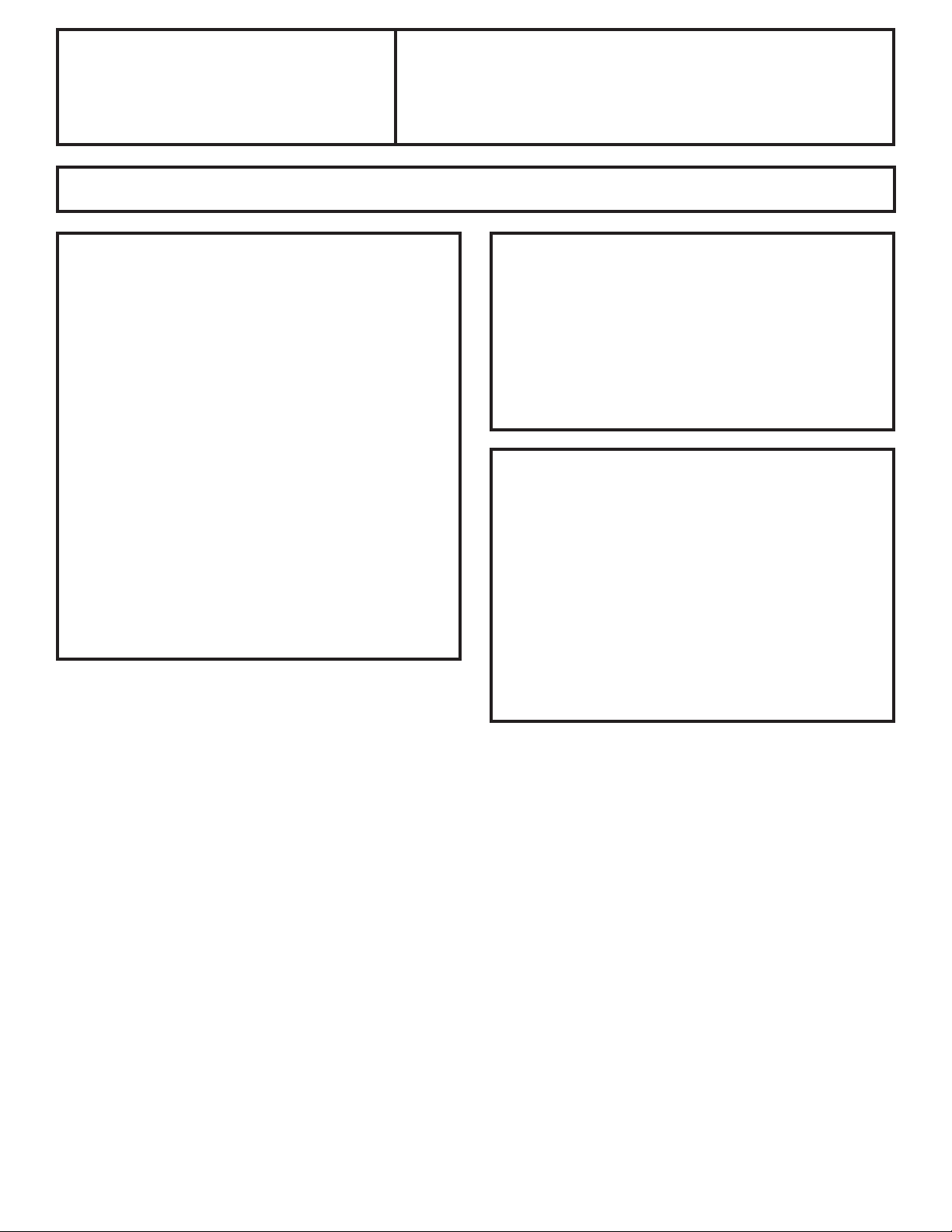
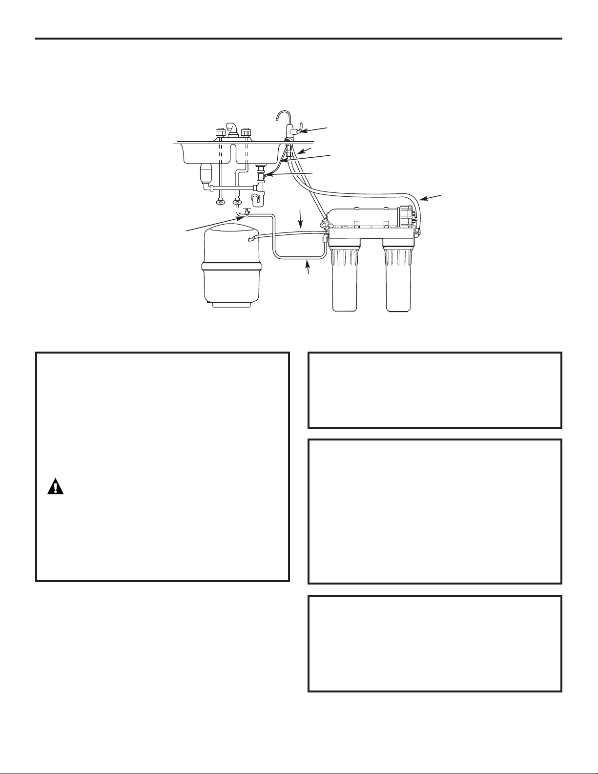
RO FAUCET
The RO product water faucet installs on the sink
or on the countertop next to the sink. Often, it is
installed in an existing sink spray attachment hole
or a hole may be drilled. Space is required
underneath for tubing to and from the faucet,
and for securing the faucet in place. All faucet
connections and installation procedures are done
on or above the sink or countertop. Refer to
illustration above.
Storage tank
Saddle valve
HOT
Drain adapter
3/8″ black drain tubing
RO product water faucet mounted through sink
or countertop
Yellow
(inlet)
Orange
1/4″ black
Blue
(to faucet)
COLD
Installation Instructions
WATER SUPPLY
Check and comply with local plumbing codes as you plan, then install a cold water supply fitting. For new home
installation using standard plumbing fittings, see first two illustrations below. A typical installation for existing homes
using the saddle valve is shown in the third illustration below.
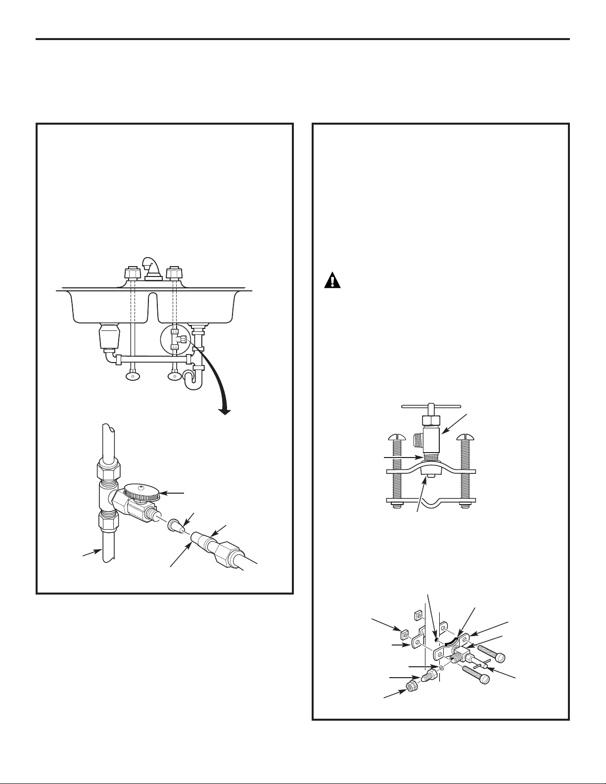
B. OPTIONAL HOME INSTALLATION
(Where codes permit)
*For 1/4″ OD or larger metal tubing only.
NOTE: Codes in the state of Massachusetts require
installation by a licensed plumber and do not
permit the use of the saddle valve. For installation,
use plumbing code 248-CMR of the Commonwealth
of Massachusetts.
1. Turn off the cold water supply and attach
saddle valve as shown in illustration below.
DANGER: To protect yourself from
serious injury or fatal shock, use a battery-
powered hand drill only to make the hole.
DO NOT USE AN ELECTRIC DRILL.
2. Close the water supply valve by turning the
handle clockwise.
3. Open the main water supply valve and several
house faucets to purge air from the system.
Close faucets when water runs smoothly.
Optional water supply connection (using saddle valve)*
Pre-drill
1/4″ hole
Seal—make sure the seal
is in place
Clamp X
Nut (2)—not
required if holes
in clamp are
threaded
Valve
Handle
Tubing adapter
Washer
Compression nut
❵
Clamp Z
Use to connect the tubing
*For 1/4″ OD or larger metal tubing only.
6
WATER SUPPLY
A. PREFERRED INSTALLATION
1. Turn off the cold water supply.
2.
Complying with plumbing codes, install a fitting
on the cold water pipe to adapt 3/8
″
OD tubing.
A typical connection is shown in the illustrations
below (parts not included). Make sure a water
supply valve is used.
Preferred water supply connection (using
compression fitting)
Insert (not included)
Cold
water
pipe
3/8
″ Tubing to inlet
Ferrule
Water supply valve
(not included)
Typical location
Cold
water
Snug valve into bracket
DO NOT OVERTIGHTEN
Some threads
should be visible
Rubber gasket
Installation Instructions
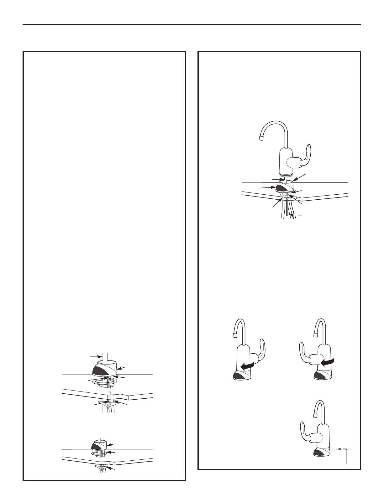
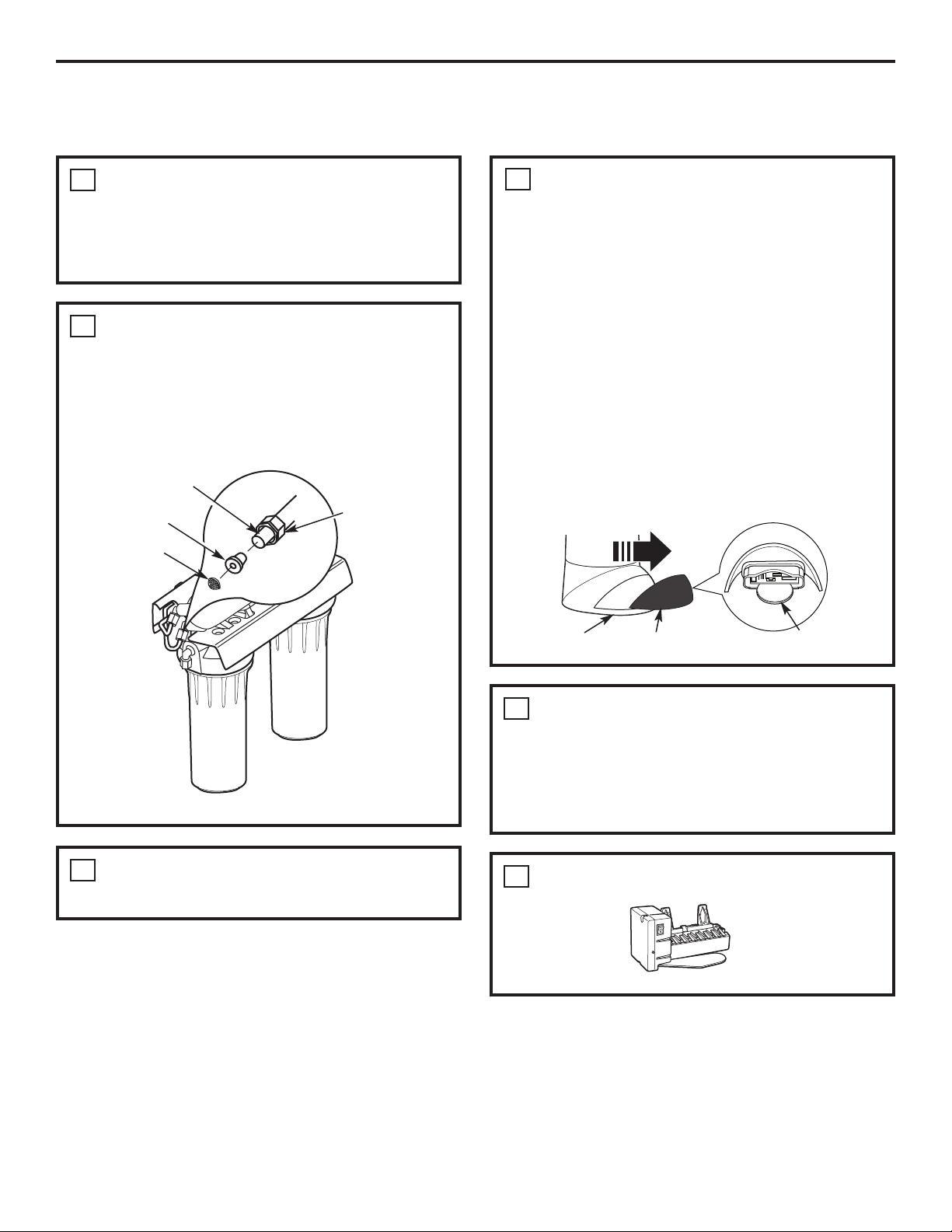
FAUCET INSTALLATION
INSTALL THE FAUCET (CONT.)
5. Tighten the toggle screw until the base is firmly
in place and does not wobble or turn.
6. Push the 3/8″ blue tube up to connect
it to the fitting on the bottom of the faucet body.
It should go in about 3/4″. Pull tube slightly to
make sure it is secure.
7. Push the faucet body down into the faucet base
and twist clockwise until it stops into place.
NOTE: You can install the faucet so the handle
is on the right or the left side.
If you want the faucet handle on the right,
position the handle at the back of the faucet
base before turning clockwise.
If you want the faucet handle on the left,
position the handle at the front of the faucet
base before turning clockwise.
8. Locate the hole at the rear
of the base. Insert set screw
and begin to tighten by
hand. Finish tightening
with the Allen wrench
provided in the packet.
DO NOT OVERTIGHTEN.
Faucet body
Faucet base
Sink
Gasket
Toggle screw
3/8″ Black tube
INSTALL THE FAUCET
Be sure there is room underneath and above
the sink to make the needed connections. Before
starting, make sure there is sufficient room for the
faucet base and unit. Select one of the following
places to install the faucet:
A. In an existing sink spray attachment or soap
dispenser hole.
B. In a hole to be drilled in the sink top.
C. In a hole to be drilled in the countertop, next
to the sink.
NOTES:
• Be sure the faucet base will fit flat against the
surface at the selected location so the bottom
gasket between the base and surface area
will seal.
• Make sure to leave enough clearance at the back
of the faucet in case you need to remove it.
Installation Steps (refer to illustration below
for clarification)
1. If drilling is needed, make a 1
1
⁄2″ diameter hole.
Be sure to use the proper procedure for drilling
porcelain or stainless steel. Special drill bits
may be needed. Consult a qualified plumber
for the proper procedure.
NOTE: When drilling in stainless steel, the edges
may be sharp and could puncture the tube. Be
careful to not cut yourself or damage the tube.
2. Remove the faucet body and base by turning
the base counterclockwise.
3. Push the 1/4″ black tube and the 3/8″ black tube
onto the correct barb fittings on the faucet base.
Push the 3/8″ blue tube through the base.
4. Align the gasket to cover the hole completely. Then
place the toggle screw on the base into the hole.
Faucet base
Sink
Gasket
Toggle screw
1/4″ Black tube
Faucet base
1/4″ Barb fitting
1/4″ Black tube
3/8″ Barb fitting
3/8″ Black tube
3/8″ Blue tube
3/8″ Blue tube
Mounting screw
Faucet Faucet
Faucet handle on the RIGHT Faucet handle on the LEFT
7
Installation Instructions
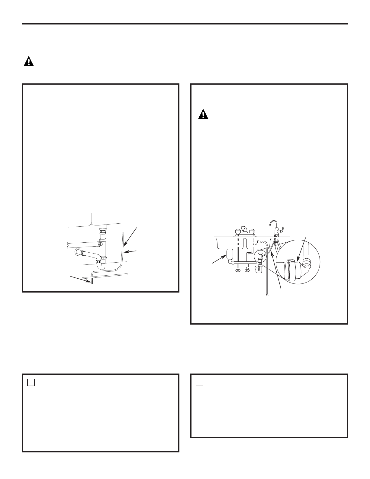
FILTRATION DRAIN CONNECTION INSTALLATION
Check and comply with all state and local plumbing codes as you plan.
CAUTION: The options detailed in this section are the ONLY approved installation configurations.
Do not use any drain saddle device.
OPTION A: BASEMENT ACCESS
INSTALLATION
Route the drain line (1/4″ black line) DIRECTLY from
the Reverse Osmosis system to a standpipe in the
basement, bypassing the air gap provided in the
faucet. The drain line may also be routed in the
basement to a floor drain or washtub, provided
that the air gap in the basement is maintained.
Avoid dips, loops or low spots in the drain line.
The basement air gap and drain installation
configuration must conform to all local codes.
Special air gap fittings are available from your
local hardware store to connect the drain line
to the top of the standpipe.
Drain line from Reverse
Osmosis bypassing
faucet air gap
Maintain air gap
at drain point
in basement
1/4″ Black
tubing
OPTION B: DRAIN LINE ADAPTER
INSTALLATION
CAUTION!
DO NOT INSTALL DRAIN LINE ADAPTER
DOWNSTREAM FROM DISPOSER.
Install the provided drain line adapter under the sink
as shown. The baffle-tee provided must be in place
(purchase and install if necessary) to prevent a clog
in the Reverse Osmosis drain line. Route the drain line
(3/8″ black) from the faucet air gap to the drain line
adapter, ensuring that there are no dips, loops or low
spots in the line that could result in a clogged
drain line.
The tubing must be cut to length to provide
a straight routing from the faucet to the drain.
Drain noise in the sink drain is normal when the
Reverse Osmosis system is operating.
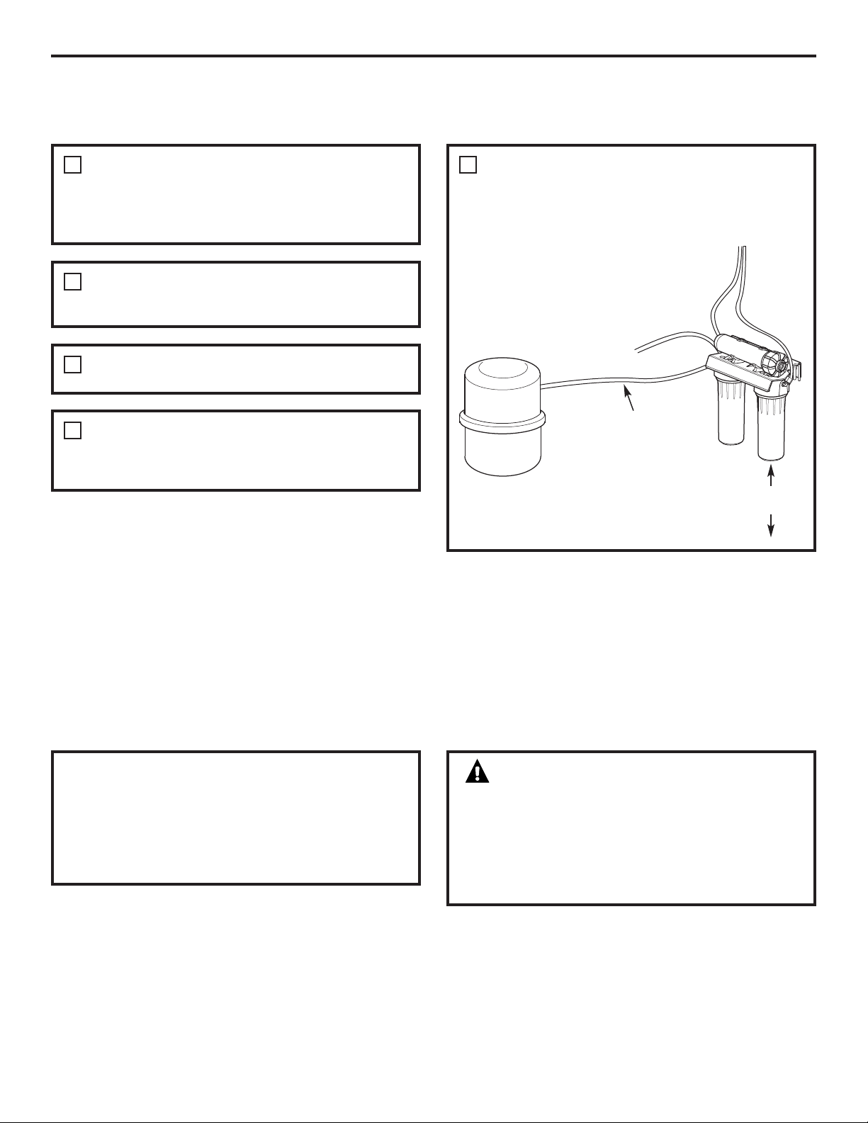
FAUCET DRAIN TUBING AND WATER SUPPLY TUBING
If OPTION A: BASEMENT ACCESS INSTALLATION (see Filtration Drain Connection Installation section, above) was
used, go to Step 2.
If OPTION B: DRAIN LINE ADAPTER
INSTALLATION was used, connect the faucet
drain tubing by running the 3/8″ black tubing
from the 3/8″ faucet barb to the drain fitting
(installed in Filtration Drain Connection
Installation section, above). Keep this tubing run
as short and straight as possible, without loops,
dips or low spots. Cut the tubing as needed and
insert into the drain fitting.
1
To connect the water supply tubing:
Run the 1/4″ yellow tubing from the Reverse
Osmosis inlet to the water supply fitting
(on illustrations in the Water Supply section
on page 6). Connect the tubing as applies
(see Water Supply section) and tighten the
nut securely.
2
Drain line adapter
in different line
from disposer
HOT COLD
Disposer
Drain line is straight
8
Installation Instructions
9
REVERSE OSMOSIS SYSTEM ASSEMBLY
AND STORAGE TANK INSTALLATION
NOW THAT YOUR REVERSE OSMOSIS SYSTEM
IS INSTALLED…SANITIZE!
Sanitize upon installation and after servicing inner
parts, including replacement of prefilter, postfilter
and the Reverse Osmosis cartridge. It is important
to wash hands with anti-bacterial soap before
handling inner parts of the system. See the
Sanitization section.
CAUTION: If installing unit in new
construction, ensure that house plumbing is
flushed thoroughly before opening the water
supply valve. Also, before sanitizing, be sure
to remove all cartridges as described in the
Sanitization section. Chlorine will destroy the
Reverse Osmosis cartridge.
Hold the Reverse Osmosis assembly up
to the wall surface where you will install it. Mark
locations for the screws. The arrows on the top of
the bracket show the location of the screw holes.
1
Connect the tubing to the storage tank: Run the
length of 3/8″ orange tubing from the tee fitting
on the Reverse Osmosis module to the tank inlet
fitting.
5
Wood screws are included for fastening to a wood
surface. Provide other screws as needed.
2
Hang the Reverse Osmosis assembly on the screws.
3
Apply pipe thread sealing tape to the tank fitting.
Insert into tank threads. Tighten with a wrench.
4
Storage
tank
To faucet
Supply line
Orange tubing
2″ minimum clearance
for changing cartridges
Installation Instructions
10
PREFILTER, POSTFILTER AND RO CARTRIDGE REPLACEMENT
PROCEDURE, INCLUDING SANITIZATION
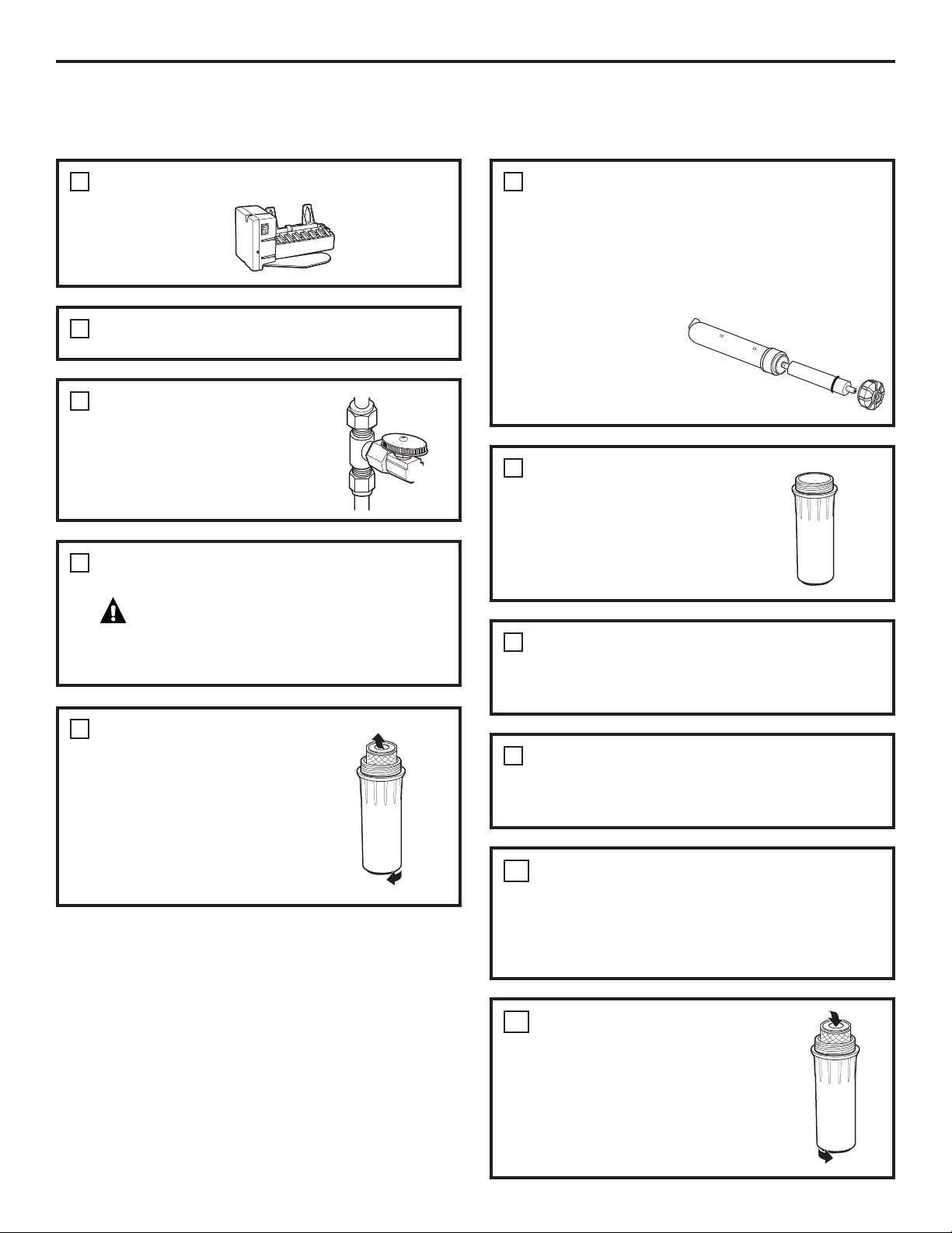
Turn OFF the icemaker (if attached to the
RO system).
1
Wash your hands with anti-bacterial soap.
2
Turn off water supply
to RO system.
3
Remove cap from RO cartridge housing (unscrew
tubing first, on some models). Use pliers to remove
the RO cartridge. Place in a clean plastic bag or
discard if replacing. Thoroughly wipe inside of
housing and cap with a paper towel or dish brush
moistened with dish soap. Rinse well. Install RO
cartridge housing cap.
NOTE: Failure to
remove RO cartridge
during sanitization
will destroy the RO
cartridge.
6
Turn on RO faucet. Drain tank (may take several
minutes). Turn off RO faucet.
CAUTION: Failure to close the water
supply valve or tank shut-off valve will cause water
to spray or run when sumps are removed.
4
Remove the sumps.
Be careful—sumps will be full
of water.
Discard filters. Thoroughly
wash sumps with dish soap.
Thoroughly wipe inside of heads
with a paper towel moistened
with dish soap. Rinse well.
5
Install empty postfilter sump.
7
Fill prefilter sump with water to within 1″
of O-ring. Add 2 oz. (4 Tbsp.) ordinary household
bleach. Install prefilter sump.
8
Turn on water supply. Open RO faucet until water
begins to flow, then close. Allow system to fill for
1 minute.
9
Open faucet and allow water to flow for
10 minutes. Close faucet for one minute more,
then open and allow water to flow for another
10 minutes, or until bleach odor is gone. Turn
off water supply again. Drain RO.
10
Remove sumps. Insert filters.
Lubricate O-ring with food-grade
silicone grease, if necessary. (Do not
use petroleum jelly.) Tighten sumps
securely.
11
Installation Instructions
11
Remove cap from RO cartridge housing. Install
RO cartridge, O-ring end first. Lubricate cover O-
ring with food-grade silicone grease, if necessary.
(DO NOT use petroleum jelly.) Tighten cap
securely.
12
If you only replaced the prefilter and postfilter,
allow faucet to run 5 minutes to remove
harmless carbon particles. If you replaced the
RO cartridge, fill and empty the storage tank
three times, until taste and odor from food-grade
membrane preservative is gone.
16
Once storage tank is full, turn on icemaker.
17
Turn on water supply. Allow to fill. (May take up to
four hours.) Check for leaks.
14
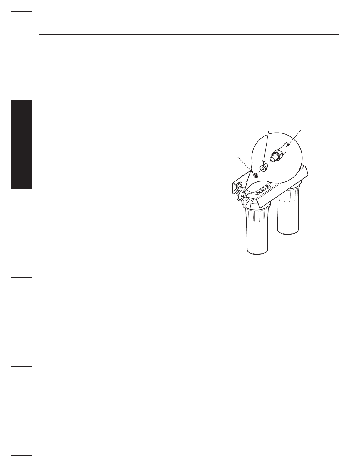
If you replaced the RO cartridge, also replace the
flow control and screen. (Unscrew the black 1/4″
line from the fitting. Remove flow control with
clean knife edge. Remove screen with a clean
toothpick.) Tighten the nut hand-tight and then
tighten 1/4 turn with pliers. DO NOT
OVERTIGHTEN.
13
Flow control
Screen
Compression nut
1/4″ Black tubing
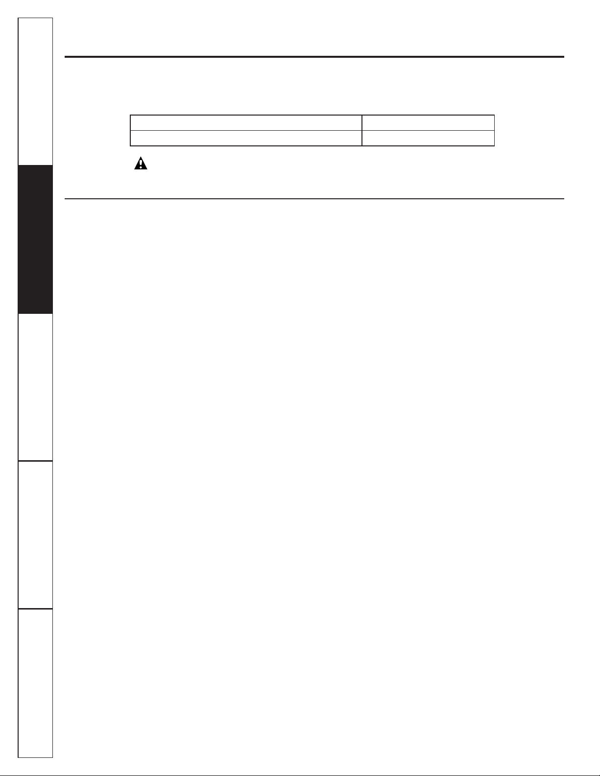
INSTALL THE BATTERY
1. Remove the lens cover from the faucet base.
Grip it from both sides and pull forward.
2. Install one CR2032 3V battery with the “+” side
down into the battery tray.
3. The amber LED light will flash 5 times, indicating
a proper installation and system reset.
4. Slide the lens cover back into the faucet base.
5. Normally, the light is off. After 6 months of use,
the amber LED light will flash every 30 seconds,
indicating the time to replace the filter canister.
NOTE: The amber LED light may stop blinking
if it is allowed to blink for an extended period
of time. To ensure proper operation, the battery
should be replaced with every filter change.
Faucet base
Lens cover
Battery “+”side down
15
Care and cleaning of the reverse osmosis system.
To obtain replacement filters, call toll-free GE Appliance Parts at 800.626.2002 (U.S.),
800.663.6060 (Canada–English), 800.361.3869 (Canada–French) or visit the store
where you purchased your reverse osmosis system.
CAUTION: Before servicing the Reverse Osmosis system, close the water supply/saddle
valve and open the RO water faucet. Allow the system to drain.
Prefilter/Postfilter Cartridge Replacement FX12P Carbon Block
Reverse Osmosis Cartridge Replacement FX12M Thin Film Polyamide
The Water Test Kit
To obtain an independent laboratory water test kit, please call Legend Technical Services at
1.800.826.8553, ext. 47, and leave your contact details. They will contact you to find out what water
tests you are interested in and inform you of the cost of the testing. You will then receive a kit that will
include all necessary tests to properly indicate the performance level of your system. Product water
should be tested a minimum of every 6 months.
Troubleshooting TipsConsumer Support Troubleshooting Tips
Installation
Instructions
Safety Instructions
Operating Instructions
12
Consumer SupportTroubleshooting Tips
Operating Instructions
Safety Instructions
Installation
Instructions
13
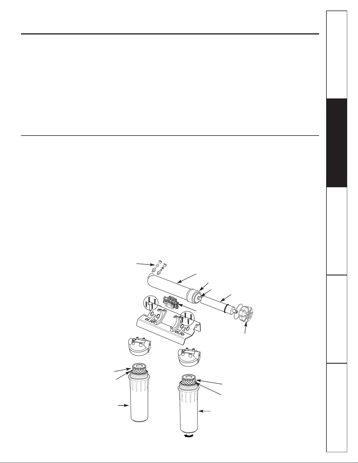
Description of the Reverse Osmosis System
Prefilter—Water from the cold supply pipe is
directed to the prefilter cartridge, which is inside
the sump.
The prefilter is a replaceable sediment
cartridge containing activated carbon. The cartridge
reduces sand, silt, dirt, other sediments and up to
2.0 ppm of aesthetic chlorine from the water. The
prefilter reduces chlorine in the water because
CHLORINE DESTROYS THE REVERSE OSMOSIS
MEMBRANE. Filtered, clean, aesthetic chlorine-
reduced water flows from the prefilter to the
Reverse Osmosis cartridge.
Storage Tank—The storage area holds up to
3 gallons of product water. A diaphragm inside
the tank keeps water pressurized for fast flow
to the faucet when drinking water is needed.
Check Valve—A check valve is built into one end
of the Reverse Osmosis housing. The check valve
prevents a backward flow of product water from
the storage area. A backward flow could cause
the Reverse Osmosis membrane to rupture.
Automatic Shutoff Valve—To conserve water, the
drinking water system has an automatic shutoff.
When the storage tank has filled to capacity and the
drinking water faucet is closed, pressure closes the
shutoff. Water flow to the Reverse Osmosis housing
is shut off until drinking water is used again, and
pressure drops in the Reverse Osmosis system.
About the reverse osmosis system. GEAppliances.com
What the Reverse Osmosis System Does
Reverse Osmosis removes Total Dissolved Solids
(TDS) and other contaminates, as specified on page
3, from the water by diffusing it through a special
membrane. High-quality product water goes
directly to the drinking water faucet or to the
storage tank. The system makes a good supply
of drinking water each day; see Specification
Guidelines. How much it makes depends on the
water supply pressure, temperature and quality.
The carbon prefilter and postfilter are replaceable
cartridges. The prefilter reduces chlorine taste and
odor while also filtering sediments. The postfilter
reduces any other undesirable taste and odors
before you use the water.
Sump
Postfilter
cartridge
Prefilter cartridge
Reverse Osmosis cartridge
Reverse Osmosis housing
Turn sump this way to remove
O-ring housing
Reverse Osmosis
housing cap
Sump
O-ring on top lip of sump
O-ring on top lip of sump
O-ring end
Check valve
Automatic
shutoff valve
Reverse Osmosis Cartridge—The cartridge, inside
the Reverse Osmosis housing, includes a tightly
wound, special membrane. Water is forced through
the cartridge where the membrane reduces the
dissolved solids and other contaminants, as specified
on page 3. High-quality product water exits the
Reverse Osmosis housing and goes to the storage
tank. Reject water, with the dissolved solids and
other contaminants, as specified on page 3, leaves
the housing and is discharged to the drain through
tubing.
Postfilter—After leaving the storage area,
but before going to the system faucet, product
water goes to the postfilter which is inside the
sump. The postfilter is also a replaceable sediment
cartridge that contains activated carbon. Any
remaining tastes, odors or sediments are reduced
from product water by the postfilter. Clean, high-
quality drinking water flows through the tubing
and to the system faucet.
System Monitor—
A timer is provided in the faucet
base to remind you when it is time to replace your
prefilter and postfilter. Replace the filters when the
amber light begins to flash in order to protect the
RO membrane and keep the system functioning
properly. Be sure to remove and replace the
battery at the same time to reset the timer.
Flow Control—The flow control regulates the flow
of water through the Reverse Osmosis cartridge at
the required rate to produce high-quality water.
The control is located in the Reverse Osmosis
housing drain port. A small, cone-shaped screen
fits over the front end of the flow control to prevent
clogging due to sediments in drain water. The flow
control and screen should be replaced each time
the Reverse Osmosis membrane cartridge is
changed.
About the reverse osmosis system.
Screen
Flow control
1/4″ black tubing
(to drain)
14
Troubleshooting TipsConsumer Support Troubleshooting Tips
Installation
Instructions
Safety InstructionsOperating Instructions
Consumer Support
Troubleshooting Tips
Operating Instructions
Safety Instructions
Installation
Instructions
Before you call for service… GEAppliances.com
Problem Possible Causes What To Do
Sounds you might hear Running water from the unit • This is normal.
to a drain.
Water has air bubbles Air in system after installation. • Will go away after water runs for a while.
and is cloudy
Chlorine taste and/or The ppm of chlorine in your
• If the water supply contains more than 2.0 ppm of
odor in the Reverse water supply exceeds maximum aesthetic
chlorine,
additional filtering of the water supply to
Osmosis product water limits and has destroyed the the Reverse Osmosis is needed. Correct this condition
Reverse Osmosis membrane. before doing maintenance on the Reverse Osmosis system.
The prefilter is no longer • Replace the Reverse Osmosis membrane cartridge,
removing aesthetic chlorine flow control, screen, prefilter and postfilter.
from the water supply.
Other taste and/or odor High-quality product water • This is normal.
may have a different taste
than what you’re used to.
Low water usage. • Completely drain system and allow to refill.
Contamination in product
•
Use sanitizing procedures.
water storage.
Prefilter and postfilter
• Replace the prefilter and postfilter. If taste and odor
need to be changed and/or persists, replace the Reverse Osmosis cartridge, flow
the Reverse Osmosis cartridge control and screen.
needs to be changed.
Water leaking from Drain side of faucet air gap • Inspect and eliminate restriction or plug. It is important
faucet air gap hole (3/8″ tubing) plugged, restricted that there are no dips, loops or low spots in the drain line
or incorrectly connected to the from the faucet air gap to the drain pipe. Refer to the
drain point. Filtration Drain Connection section, for proper drain
connection. If drain line adapter was used as the
drain
point, periodic inspection/cleaning is recommended.
System makes product This is normal. • Water flow rate will be lower than your regular faucet.
water slowly
Water supply to the Reverse • Increase water pressure, precondition the water, etc.,
Osmosis system not within as needed to conform to specification guidelines before
specifications. doing maintenance on the Reverse Osmosis system.
Prefilter cartridge plugged • Replace the prefilter and postfilter.
If rate does not
with sediments and/or the
increase,
replace the Reverse Osmosis cartridge, flow
Reverse Osmosis cartridge control and screen.
plugged with sediments.
Faucet light blinking Prefilter and postfilter • Replace filters. Don’t forget to sanitize the system when
need replacing. replacing filters.
Timer was not reset when filters • Remove and replace battery in faucet base.
were replaced.
Six months have passed Battery may be dead. • Replace battery. NOTE: Replacing the battery resets the
and faucet light is not six-month timer, so be sure to replace
the prefilter and
blinking postfilter if it is time to do so.
Battery may have been • Any time the battery is removed and reinserted, the
removed recently. six-month timer starts over again. Do not remove
the battery unless you wish to restart the timer.
Troubleshooting Tips
Save time and money! Review the chart first and you
may not need to call for service.
15
* NOTE: Codes in the State of Massachusetts require installation by a licensed plumber
and do not permit the use of the saddle valve. For installation, use plumbing code
248-CMR of the Commonwealth of Massachusetts.
Parts list.
Consumer Support Troubleshooting Tips
Operating Instructions
Safety Instructions
Installation
Instructions
16
Optional Accessories

17
Consumer SupportTroubleshooting Tips
Operating Instructions
Safety Instructions
Installation
Instructions
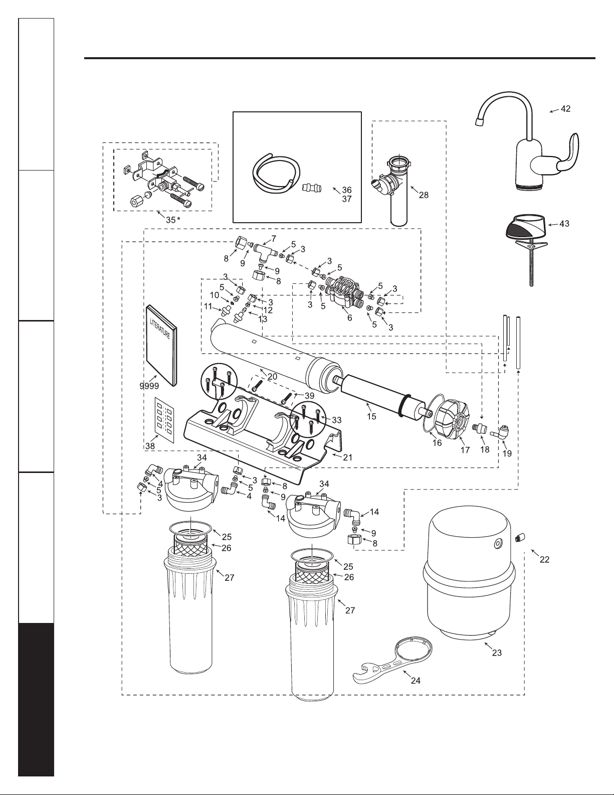
General Electric parts catalog. GEAppliances.com
REF. NO. PART NO. PART DESCRIPTION GXRM10RBL
0003 WS22X10005 1/4″ NUT 10
0004 WS22X10026 3/8″ NPT X 1/4″ NUT ELBOW 2
0005 WS22X10006 1/4″ TUBE INSERT 8
0006 WS22X10038 VALVE—AUTO SHUT OFF 1
0007 WS22X10039 1/4″ X 3/8″ X 3/8″ TUBE TEE 1
0008 WS22X10008 3/8″ NUT 4
0009 WS22X10007 3/8″ TUBE INSERT 4
0010 WS22X10040 CHECK VALVE—1/4″ INSERT 1
0011 WS22X10041 1/8″ NPT X 1/4″ FITTING 1
0012 WS03X10016 FLOW CONTROL 1
0013 WS03X10015 CONE SCREEN 1
0014 WS22X10002 3/8″ NPT X 3/8″ NUT ELBOW 2
0015 FX12M RO MEMBRANE 1
0016 WS03X10045 O-RING—RO MEMBRANE HSNG 1
0017 WS31X10025 CAP—RO MEMBRANE HSNG 1
0018 WS22X10042 1/8″ NPT X 1/4″ FITTING 1
0019 WS22X10043 ELBOW—1/4″ STEM X 1/4″ 1
0020 WS20X10006 HOUSING—RO MEMBRANE 1
0021 WS28X10039 BRACKET 1
0022 WS22X10044 CONNECTOR—3/8″ X 3/8″ MNPT 1
0023 WS32X10019 STORAGE TANK 1
0024 WX5X140 WRENCH 1
0025 WS03X10038 O-RING, SUMP HOUSING 2
0026 FX12P CARBON BLOCK CARTRIDGE 2
0027 WS20X10007 SUMP HOUSING 2
0028 WS18X10006 DRAIN LINE ADAPTER—DLA9 1
0033 WS02X10032 SCREWS, BRACKET 8
0034 WS31X10026 HOUSING HEAD 2
0035 WS15X10023 SADDLE VALVE 1
0036 WS07X10018 TUBING—1/4″ X 33′—WHITE 1
0037 WS07X10019 TUBING—3/8″ X 33′—WHITE 1
0038 WS01X10013 NITRATE TEST STRIP 1
0039 WS02X10033 MOUNTING SCREWS 2
0042 WS15X10070 FAUCET BODY AND SPOUT 1
0043 WS10X10041 3/8″ QUICK CONNECT BASE—FAUCET 1
9999 49-50237 OWNER’S MANUAL/INSTALLATION 1
INSTRUCTIONS
* NOTE: Codes in the State of Massachusetts require installation by a licensed plumber
and do not permit the use of the saddle valve. For installation, use plumbing code
248-CMR of the Commonwealth of Massachusetts.
To obtain replacement parts, call toll-free 800.626.2002 (U.S.), 800.663.6060
(Canada–English), 800.361.3869 (Canada–French).

18
Notes.
Consumer Support Troubleshooting Tips
Operating Instructions
Safety Instructions
Installation
Instructions
Loading...