


INSTALLATION AND OPERATION
SX TRANSISTOR CONTROL Page 1
SEPARATELY EXCITED (SX) TRANSISTORIZED DUAL MOTOR TRACTION CONTROL
AND SERIES PUMP CONTROL
INSTALLATION AND OPERATION MANUAL
(IC3645SR4U404N2 and IC3645SP4U400N3)
Note: The information contained herein is intended to assist OEM's, Dealers and Users of electric vehicles in the application, installation and service of GE solid-state controllers. This manual does not purport to cover all variations in OEM vehicle types. Nor does it provide for every possible contingency to be met involving vehicle installation, operation or maintenance. For additional information and/or problem resolution, please refer the matter to the OEM vehicle manufacturer through his normal field service channels. Do not contact GE directly for this assistance.
Table of Contents
|
|
Copyright by General Electric Company January 2000 |
|
Section 1.0 |
INTRODUCTION ........................................................................................................................................................ |
4 |
|
|
1.1 |
Motor Characteristics .............................................................................................................. |
4 |
|
1.2 |
Solid-State Reversing............................................................................................................... |
5 |
|
1.3 |
Flexible System Application..................................................................................................... |
5 |
|
1.4 |
More Features with Fewer Components ................................................................................ |
5 |
Section 2.0 |
FEATURES OF SX FAMILY OF MOTOR CONTROLLERS .................................................................................... |
6 |
|
|
2.1 |
Performance.............................................................................................................................. |
6 |
|
2.1.1 |
Oscillator Card Features .................................................................................................. |
6 |
|
2.1.1.a |
Standard Operation .................................................................................................. |
6 |
|
2.1.1.b |
Creep Speed............................................................................................................... |
6 |
|
2.1.1.c |
Controlled Acceleration .......................................................................................... |
6 |
|
2.1.2 |
Current Limit ...................................................................................................................... |
6 |
|
2.1.3 |
Braking ............................................................................................................................... |
6 |
|
2.1.3.a |
Plug Braking .............................................................................................................. |
6 |
|
2.1.3.b |
Regenerative Braking to Zero Speed...................................................................... |
6 |
|
2.1.3.c |
Pedal Position Plug Braking .................................................................................... |
6 |
January 2000

INSTALLATION AND OPERATION
|
SX TRANSISTOR CONTROL |
|
Page 2 |
|
|
|
|
|
|
|
|
|
Table of Contents ( Continued ) |
|
|
|
2.1.3.d |
Auto Braking.............................................................................................................. |
6 |
|
|
2.1.4 |
Auxiliary Speed Control.................................................................................................... |
6 |
|
|
2.1.4.a |
Field Weakening................................................................................................................ |
6 |
|
|
2.1.4.b |
Speed Limits ...................................................................................................................... |
7 |
|
|
2.1.4.c |
Proportional Operation for Dual Motor Vehicles .......................................................... |
7 |
|
|
2.1.5 |
Ramp Operation ................................................................................................................ |
7 |
|
|
2.1.5.a |
Ramp Start ................................................................................................................. |
7 |
|
|
2.1.5.b |
Anti-Rollback ............................................................................................................. |
7 |
|
|
2.1.6 |
Steer Pump Contactor Time Delay ................................................................................. |
7 |
|
|
2.1.7 |
On-Board Coil Drivers and Internal Coil Suppression ................................................. |
8 |
|
|
2.2 |
System Protective Override ..................................................................................................... |
8 |
|
|
2.2.1 |
Static Return to Off (SRO) ............................................................................................... |
8 |
|
|
2.2.2 |
Accelerator Volts Hold Off............................................................................................... |
8 |
|
|
2.2.3 |
Pulse Monitor Trip (PMT)................................................................................................. |
8 |
|
|
2.2.4 |
Thermal Protector (TP)..................................................................................................... |
8 |
|
|
2.2.5 |
Low Voltage .................................... .................................................................................. |
8 |
|
|
2.3 |
Diagnostics................................................................................................................................ |
8 |
|
|
2.3.1 |
Systems Diagnostics...................................... .................................................................. |
8 |
|
|
2.3.2 |
Status Codes...................................................................................................................... |
8 |
|
|
2.3.2.a |
Standard Status Codes............................................................................................. |
8 |
|
|
2.3.2.b |
Stored Status Codes ......................................... ....................................................... |
8 |
|
|
2.3.3 |
Hourmeter Readings ........................................................................................................ |
9 |
|
|
2.3.3.a |
Maintenance Alert and Speed Limit .................... .................................................. |
9 |
|
|
2.3.4 |
Battery Discharge Indication (BDI)....................... ......................................................... |
9 |
|
|
2.3.4.a |
Internal Resistance Compensation ................................................................................ |
9 |
|
|
2.3.5 |
Handset ................................................. ............................................................................ |
9 |
|
|
2.3.6 |
RS-232 Communication Port ........................................................................................... |
9 |
|
|
2.3.6.a |
Dash Display Interaction Modes ................... ............................................................... |
9 |
|
|
2.3.7 |
Circuit Board Coil Driver Modules........................ .......................................................... |
9 |
|
|
2.3.8 |
Truck Management Module (TMM) ............................................................................... |
9 |
|
|
2.4 |
Hydraulic Pump Control........................................................................................................... |
9 |
|
Section 3.0 |
ORDERING INFORMATION, ELEMENTARY AND OUTLINE DRAWINGS...................................................... |
11 |
|
|
|
3.1 |
Ordering Information for Separately Excited Controls................................................................. |
11 |
|
|
3.2 |
Outline: SX-3 and SR-3 Package Size............................................................................................. |
12 |
|
|
3.3 |
Traction Elementary ......................................................................................................................... |
13 |
|
|
3.4 |
Pump Elementary.............................................................................................................................. |
14 |
|
|
3.5 |
Traction and Pump Control Input / Output List ............................................................................. |
15 |
|
Section 4.0 |
TROUBLESHOOTING AND DIAGNOSTIC STATUS CODES.............................................................................. |
16 |
|
|
|
4.1 |
General Maintenance Instructions................................................................................................. |
16 |
|
|
4.2 |
Cable Routing and Separation ............................................................................................... |
16 |
|
|
4.2.1 |
Application Responsibility ............................................................................................... |
16 |
|
|
4.2.2 |
Signal/Power Level Definitions ............................................................................................... |
16 |
|
|
4.2.2.a |
Low Level Signals (Level L) .............................................................................................. |
16 |
|
|
4.2.2.b |
High Level Signals (Level H)............................................................................................. |
17 |
|
|
4.2.2.c |
Medium-Power Signals (Level MP) ................................................................................ |
17 |
|
|
4.2.2.d |
High-Power Signals (Level HP) ....................................................................................... |
17 |
|
|
4.2.3 |
Cable Spacing Guidelines ........................................................................................................ |
17 |
|
|
4.2.3.a |
General Cable Spacing..................................................................................................... |
17 |
|
|
4.2.4 |
Cabling for Vehicle Retrofits.................................................................................................... |
17 |
January 2000

INSTALLATION AND OPERATION
|
SX TRANSISTOR CONTROL |
|
Page 3 |
||
|
|
|
|
|
|
|
|
|
Table of Contents ( Continued ) |
|
|
|
|
|
|
|
|
|
|
4.2.5 |
RF Interference.......................................................................................................................... |
17 |
|
|
|
4.2.6 |
Suppression............................................................................................................................... |
17 |
|
|
|
4.3 |
Recommended Lubrication of Pins and Sockets Prior to Installation........................................ |
18 |
|
|
|
4.4 |
General Troubleshooting Instructions ........................................................................................... |
19 |
|
|
|
4.5 |
Traction Controller Status Codes ................................................................................................... |
20-40 |
|
|
|
4.6 |
TMM Status Codes........................................................................................................................... |
41-45 |
|
|
|
4.7 |
Pump Control Status Codes............................................................................................................. |
46-52 |
|
|
Section 5.0 |
TRUCK MANAGEMENT MODULE (TMM)............................................................................................................ |
53 |
|
|
|
|
5.1 |
General Features .............................................................................................................................. |
53 |
|
|
|
5.2 |
Operation ...................................................... .................................................................................... |
53 |
|
|
|
5.3 |
Installation......................................................................................................................................... |
53 |
|
|
|
5.4 |
Connection Diagrams....................................................................................................................... |
53 |
|
|
|
5.4.1 |
TMM7A Card Connections ...................................................................................................... |
53 |
|
|
|
5.4.2 |
TMM7A Typical Brush Wear Sensor Connections ............ ................................................. |
53 |
|
|
|
5.4.3 |
TMM Pump Control Connections ........................................................................................... |
54 |
|
|
|
5.5 |
TMM7A Outline Drawings ............................................................................................................... |
54 |
|
|
Section 6.0 |
SX FAMILY - GE HANDSET INSTRUCTIONS ...................................................................................................... |
55 |
|
|
|
|
6.1 |
General Features .............................................................................................................................. |
55 |
|
|
|
6.2 |
Purpose/Setup Functions ............................................................................................................... |
55 |
|
|
|
6.3 |
Setup Function Procedures ............................................................................................................ |
56 |
|
|
|
6.3.1 |
Setup Mode ............................................ .................................................................................. |
56 |
|
|
|
6.3.2 |
Status Code Scrolling............................................................................................................... |
56 |
|
|
|
6.3.3 |
SX Handset Plug Connections & Outline Drawing.... ........................................................... |
56 |
|
|
|
6.4 |
Setup Functions for Traction Controller .. ..................................................................................... |
57-62 |
|
|
|
6.5 |
Summary of Current Limit Adjustments ......................................................................................... |
62 |
|
|
|
6.6 |
Setup Functions for Hydraulic Pump Controller . ......................................................................... |
64-66 |
|
|
Section 7.0 |
DASH DISPLAYS....................................................................................................................................................... |
67 |
|
|
|
|
7.1 |
Application ............................................. ............................................................................................. |
67 |
|
|
|
7.2 |
Standard Dash Displays .................................. .................................................................................. |
67 |
|
|
|
7.3 |
Interactive Dash Displays................................................................................................................... |
67 |
|
|
|
7.4 |
Start-up Display Sequence ................................................................................................................ |
68 |
|
|
|
7.5 |
Outline Drawings ........................................ ........................................................................................ |
68 |
|
|
Section 8.0 |
TURN ANGLE POTENTIOMETER INSTALLATION.............................................................................................. |
69 |
|
|
|
|
8.1 |
General................................................................................................................................................. |
69 |
|
|
|
8.2 |
320 Degree Potentiometer Input........................................................................................................ |
70 |
|
|
|
8.3 |
Turn Angle Input Volts vs. Steer Wheel Degrees vs. Handset Readings..................................... |
71 |
|
|
Section 9.0 |
MEMORY MAPS........................................................................................................................................................ |
72 |
|
|
|
|
9.1 |
Typical Memory Map for Traction Control.................................................................................... |
72-74 |
|
January 2000
BASIC OPERATION AND FEATURES
SX TRANSISTOR CONTROL Page 4
Section 1. INTRODUCTION
Section 1.1 Motor Characteristics
The level of sophistication in the controllability of traction motors has changed greatly over the past several years. Vehicle manufacturers and users are continuing to expect more value and flexibility in electric vehicle motor and control systems as they are applied today. In order to respond to these market demands, traction system designers have been forced to develop new approaches to reduce cost and improve functions and features of the overall system. Development is being done in a multigenerational format that allows the market to take advantage of today’s technology, while looking forward to new advances on the horizon. GE has introduced a second generation system using separately excited DC shunt wound motors. The separately excited DC motor system offers many of the features that are generally found on the advanced AC systems. Historically, most electric vehicles have relied have on series motor designs because of their ability to produce very high levels of torque at low speeds. But, as the demand for high efficiency systems increases, i.e., systems that are more closely applied to customers’ specific torque requirements, shunt motors are now often being considered over series motors. In most applications, by independently controlling the field and armature currents in the separately excited motor, the best attributes of both the series and the shunt wound motors can be combined.
|
SPEED |
|
|
NO LOAD CURRENT |
FULL |
LOAD CURRENT |
STARTING CURRENT |
|
TORQUE |
|
|
|
ARMATURE CURRENT |
|
|
|
Figure 1 |
|
|
As shown in from the typical performance curves of Figure 1, the high torque at low speed characteristic of the series motor is evident.
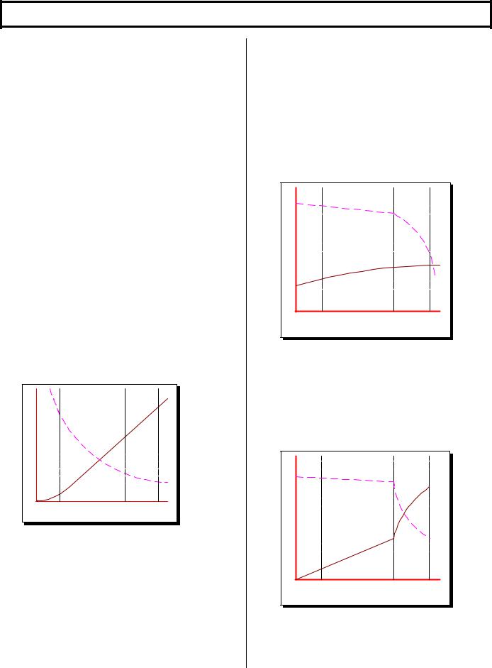
In a shunt motor, the field is connected directly across the voltage source and is therefore independent of variations in load and armature current. If field strength is held constant, the torque developed will vary directly with the armature current. If the mechanical load on the motor increases, the motor slows down, reducing the back EMF (which depends on the speed, as well as the constant field strength). The reduced back EMF allows the armature
current to increase, providing the greater torque needed to drive the increased mechanical load. If the mechanical load is decreased, the process reverses. The motor speed and the back EMF increase, while the armature current and the torque developed decrease. Thus, whenever the load changes, the speed changes also, until the motor is again in electrical balance.
In a shunt motor, the variation of speed from no load to normal full load on level ground is less than 10%. For this reason, shunt motors are considered to be constant speed motors (Figure 2).
|
SPEED |
|
|
LOADCURRENT |
FULL |
LOAD CURRENT |
STARTING CURRENT |
NO |
|
|
|
|
TORQUE |
|
|
ARMATURE CURRENT
Figure 2
In the separately excited motor, the motor is operated as a fixed field shunt motor in the normal running range. However, when additional torque is required, for example, to climb non-level terrain, such as ramps and the like, the field current is increased to provide the higher level of torque. In most cases, the armature to field ampere turn ratio can be very similar to that of a comparable size series motor (Figure 3.)
|
SPEED |
|
|
NO LOAD CURRENT |
FULL |
LOAD CURRENT |
STARTING CURRENT |
|
TORQUE |
|
|
ARMATURE CURRENT
Figure 3
Aside from the constant horsepower characteristics described above, there are many other features that provide increased performance and lower cost. The
January 2000
BASIC OPERATION AND FEATURES
SX TRANSISTOR CONTROL Page 5
following description provides a brief introduction to examples of some of these features.
Section 1. 2 Solid-State Reversing
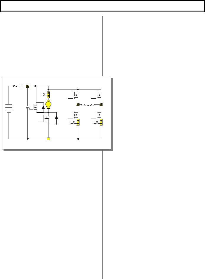
The direction of armature rotation on a shunt motor is determined by the direction in which current flows through the field windings. Because of the of the shunt motor field only typically requires about 10% of the armature current at full torque, it is normally cost effective to replace the double-pole, double-throw reversing contactor with a low power transistor H-Bridge circuit (Figure 4).
LINE |
POS |
|
|
|
|
FUSE |
|
|
|
|
|
|
|
|
|
Q3 |
Q5 |
|
|
A1 + |
|
|
|
CAP |
Q2 |
ARM |
F1 |
F2 |
|
A2 |
- |
|
|
||
|
|
|
|
||
|
|
|
|
Q4 |
Q6 |
|
|
Q1 |
|
|
|
NEG
Figure 4
By energizing the transistors in pairs, current can be made to flow in either direction in the field. The armature control circuit typically operates at 12KHZ to 15KHZ, a frequency range normally above human hearing. This high frequency coupled with the elimination of directional contactors, provides very quiet vehicle operation. The field control circuits typically operate at 2 KHZ.
The line contactor is normally the only contactor required for the shunt motor traction circuit. This contactor is used for both pre-charge of the line capacitors and for emergency shut down of the motor circuit, in case of problems that would cause a full motor torque condition. The line can be energized and de-energized by the various logic combinations of the vehicle, i.e. activate on key, seat or start switch closure, and de-energize on time out of idle vehicle. Again, these options add to the quiet operation of the vehicle.
Section 1. 3 Flexible System Application
Because the shunt motor controller has the ability to control both the armature and field circuits independently, the system can normally be adjusted for maximum system efficiencies at certain operating parameters. Generally speaking, with the ability of independent field and
armature, the motor performance curve can be maximized through proper control application.
Section 1. 4 More Features with Fewer Components
Field weakening with a series wound motor is accomplished by placing a resistor in parallel with the field winding of the motor. Bypassing some of the current flowing in the field into the resistor causes the field current to be less, or weakened. With the field weakened, the motor speed will increase, giving the effect of “overdrive”. To change the “overdrive speed”, it is necessary to change
the resistor value. In a separately excited motor, independent control of the field current provides for infinite adjustments of “overdrive” levels, between motor base speed and maximum weak field. The desirability of this feature is enhanced by the elimination of the contactor and resistor required for field weakening with a series motor.
With a separately excited motor, overhauling speed limit, or downhill speed, will also be more constant. By its nature, the shunt motor will try to maintain a constant speed downhill. This characteristic can be enhanced by increasing the field strength with the control. Overhauling load control works in just the opposite way of field weakening, armature rotation slows with the increase of current in the field.
Regenerative braking (braking energy returned to the battery) may be accomplished completely with solid-state technology. The main advantage of regenerative braking is increased motor life. Motor current is reduced by 50% or more during braking while maintaining the same braking torque as electrical braking with a diode clamp around the armature. The lower current translates into longer brush life and reduced motor heating. Solid state regenerative braking also eliminates a power diode, current sensor and contactor from the circuit.
For GE, the future is now as we make available a new generation of electric traction motor systems for electric vehicles having separately excited DC shunt motors and controls. Features that were once thought to be only available on future AC or brushless DC technology vehicles systems are now achievable and affordable.
January 2000
BASIC OPERATION AND FEATURES
SX TRANSISTOR CONTROL Page 6
Section 2. FEATURES OF SX FAMILY OF TRANSISTOR
MOTOR CONTROLLERS
Section 2.1 Performance
Section 2.1.1 Oscillator Card Features
Section 2.1.1.a Standard Operation
With the accelerator at maximum ohms or volts, the creep speed can be adjusted by Function 2 of the Handset or a trimpot. The field control section allows the adjustment of the field weakening level in order to set the top speed of the motor. This top speed function (Minimum Field Current) is enabled when the armature current is less than the value set by Function 24 and the accelerator input voltage is less than 1 volt. Top Speed can be adjusted by Function 7 of the Handset or a trimpot.
The percent on-time has a range of approximately 0 to 100 percent. The SX controllers operate at a constant frequency and the percent on-time is controlled by the pulse width of the voltage / current applied to the motor circuits.
Section 2.1.1.b Creep Speed
With the accelerator at maximum ohms or volts (approximately 3.7 to 3.5 VDC), the creep speed can be adjusted by Function 2 of the Handset. At creep speed, the ON time can decrease to approximately 5%, with the OFF time at approximately 95%. At full transistor operation, this condition will be reversed (short OFF time, long ON time). This variation of ON and OFF time of the oscillator varies the voltage applied to the motor, thereby varying the speed of the motor for a given load.
Section 2.1.1.c Control Acceleration
This feature allows for adjustment of the rate of time it takes for the control to accelerate to 100% applied battery voltage to the motor on hard acceleration. Armature C/A is adjusted by Function 3 from 0.1 to 22 seconds.
Section 2.1.2 Current Limit
This circuit monitors motor current by utilizing sensors in series with the armature and field windings. The information detected by the sensor is fed back to the card so that current may be limited to a pre-set value. If heavy load currents are detected, this circuit overrides the oscillator and limits the average current to a value set by Function 4 and Function 8 of the Handset. The C/L setting is based on the maximum thermal rating of the control. Because of the flyback current through 3REC, the motor current is usually greater than battery current, except at 100% ON time.
Section 2.1.3 Braking
Section 2.1.3.a Plug Braking
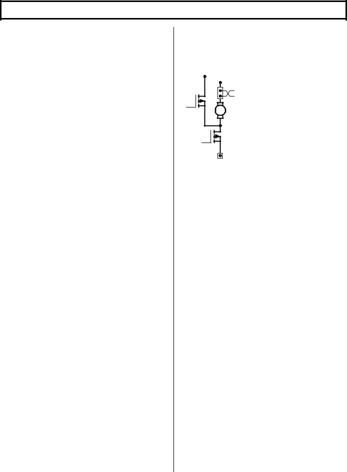
Section 2.1.3.b Regenerative Braking to Zero Speed
|
|
Slow down is accomplished when |
|
|
reversing direction by providing a |
|
|
small amount of retarding torque for |
Q2 |
|
deceleration. If the vehicle is |
|
ARM moving, and the directional lever is |
|
|
|
moved from one direction to the |
|
|
other, the regen signal is initiated. |
|
Q1 |
Once the regen signal has been |
|
initiated, the field current is |
|
|
|
|
Figure 5 |
|
increased (armature circuit shown in |
|
|
Figure 5). Armature current is |
regulated to the regen current limit as set by Function 9. As the vehicle slows down, the field current continues to increase, and transistor Q2 begins to chop. The field current will increase until it reaches a preset value set by Function 10, and transistor Q2 on-time will increase until it reaches 100% on-time. Once both of the above conditions have been met, and regen current limit can no longer be maintained, the braking function is canceled. The fields will then reverse, and the control reverts back to motoring. Part of the energy produced by the motor during regen is returned to the battery, and part is dumped in the motor as heat.
Section 2.1.3.c Pedal Position Plug Braking
This feature allows control of the plugging distance based on pedal position when there has been a “directional switch" change. Pedal position will reduce the regenerative current to the "value set by this function" as the accelerator is returned to the creep speed position. Maximum regen current is obtained with the accelerator in the top speed position.
Section 2.1.3.d Auto Braking
This feature is enabled by initiating a "neutral position" using either the directional switch or the accelerator switch. Once activated, Auto Braking operates similar to Pedal Position Plug Braking and is adjusted by using Function 21 of the Handset.
Section 2.1.4 Auxiliary Speed Control
Section 2.1.4.a Field Weakening
This function allows the adjustment of the field weakening level in order to set the top speed of the motor. The function is enabled when the armature current is less than the value set by Function 24 and the accelerator input voltage is less than 1 volt. It is important to note that this function is used
January 2000
BASIC OPERATION AND FEATURES
SX TRANSISTOR CONTROL Page 7
to optimize motor and control performance, and this setting will be determined by GE and OEM engineers at the time of vehicle development. This setting must not be changed by field personnel, without the permission of the OEM.
Section 2.1.4.b Speed Limits
This feature provides a means to control speed by limiting motor volts utilizing three "adjustable speed limits. This motor volt limit regulates top speed of the transistor controller, but actual truck speed will vary at any set point depending on the loading of the vehicle. Each speed limit can be adjustable with the Handset using Functions 11, 12, and 13.
Section 2.1.4.c Proportional Operation for Dual Motor Vehicles
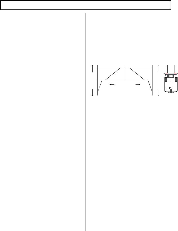
A key performance advantage of this control is the ability to achieve actual "proportioning" of motor speed. In a non-proportioning, or single control, system when the vehicle starts to turn, the outside drive wheel turns in a larger circle than the inside wheel. Depending on the geometry of the vehicle, at some degree of turn angle, the inside wheel must slow down to prevent scrubbing of the wheel. This is accomplished on single control system by disconnecting the inside motor and letting the wheel "free wheel" or "float" at whatever speed is dictated by the outside wheel that is still under power. The main disadvantage of this system is that no torque is available on that motor when the inside wheel is in the "free-wheel" mode, and performance in a turn is reduced. When the steer wheel nears to the 90° turn angle, the inside motor is re-connected in the opposite direction of the outside. At this point, torque is returned to the inside wheel and the speed is the same on both motors.
With two controls, the speed of each motor can be regulated independently. The driver controls the speed of the outside wheel with the accelerator input signal. The inside wheel speed is controlled by the turn angle of the steer wheel . A potentiometer is attached to the steer wheel in order to communicate the steer angle to the controllers. During vehicle manufacture, software selection identifies each control for its application as a right or left control. The controls are physically identical, and it is only software that separates a right from a left control or differentiates a control for a dual motor application from one intended for a single motor vehicle. As the steer reaches some pre-selected turn angle, approximately 20o, the speed of the inside wheel decrease proportionally to the speed of the outside wheel. This proportional decline will continue on a linear path until the steer angle reaches another predetermine angle of, approximately 65o.
At this point, the inside wheel will stop, as the steer angle is increased toward the 90° point, the inside wheel will reverse direction and start to accelerate proportionally in speed. As the steer angle reaches the 90° point, the inside wheel speed will be the same as that of the outside wheel. During this entire turn, except for several degrees when the motor was stopped to change direction, torque was always present on the inside wheel, providing a smoother ride throughout the turning radius of the vehicle.
Details for adjustment of the steer angle potentiometer can be found in Appendix A of this manual.
|
100% |
RIGHT |
|
LEFT |
100% |
|
|
|
|
|
|
|
|
|
|
||
- FWD |
50% |
MOTOR |
|
MOTOR |
50% |
- FWD |
|
|
|
|
|
|
|
||||
|
LEFT |
|
|
|
|
|
||
SPEED- |
90O |
|
|
90O |
SPEED- |
LEFT |
RIGHT |
|
|
80O 70O 60O 50O 40O 30O 20O 10O 0O 10O 20O 30O 40O 50O 60O 70O 80O |
|
MOTOR |
MOTOR |
||||
|
|
|
|
|
|
|||
REV |
50% |
TURN |
STEERING ANGLE |
RIGHT |
50% |
REV |
|
0O |
|
LEFT |
|||||||
|
|
|
|
TURN |
|
|
RIGHT |
|
|
|
|
|
|
|
CONTROL |
CONTROL |
|
|
100% |
|
|
|
100% |
|
90O |
90O |
Section 2.1.5 Ramp Operation
Section 2.1.5a Ramp Start
This feature provides maximum control torque to restart a vehicle on an incline. The memory for this function is the directional switch. When stopping on an incline, the directional switch must be left in its original or neutral position to allow the control to initiate full power when restarted. The accelerator potentiometer input will modulate ramp start current.
Section 2.1.5b Anti-Rollback
This feature provides retarding torque to limit rollback speed in the non-travel direction when the ACC pedal is released when stopping on a grade, or when the brake pedal is released when starting on a grade. This feature forces the vehicle to roll very slowly down the grade when accelerator or brake is released. Because the vehicle can gain significant speed during roll-back, the torque needed to re-start on the ramp is lower than an unrestricted rollback speed.
Section 2.1.6 Steer Pump Contactor Time Delay
This feature provides two options for SP time delay. Option 1 provides a 0.5 to 63 second time delayed drop out of the steer pump contactor when the Forward or Reverse directional switch is opened. This Option 1 is overridden by a 1.5 second time delayed drop out whenever the seat switch is opened. Option 2 provides a 0.5 to 63 second time delayed drop out of the SP contactor when the seat switch is opened.
January 2000

BASIC OPERATION AND FEATURES
SX TRANSISTOR CONTROL Page 8
Section 2.1.7 On-Board Coil Drivers & Internal Coil
Suppression
Coil drivers for the LINE and SP contactors
are on-board the control card. These contactors must have coils rated for the vehicle battery volts.
Section 2.2 System Protective Override
Section 2.2.1 Static Return to Off (SRO)
This inherent feature of the control is designed to require the driver to return the directional lever to the neutral position anytime he leaves the vehicle and returns. Additionally, if the seat switch or key switch is opened, the control shuts off and cannot be restarted until the directional lever is returned to neutral. A time delay of approximately 2 seconds is built into the seat switch input to allow momentary opening of the seat switch, if a bump is encountered.
Section 2.2.2 Accelerator Volts Hold Off
This feature checks the voltage level at the accelerator input whenever the key switch or seat switch is activated. If, at start up, the voltage is less than 3.0 volts, the control will not operate. This feature assures that the control is calling for low speed operation at start up.
Section 2.2.3 Pulse Monitor Trip (PMT)
The PMT design contains three features which shut down, or lock out, control operation if a fault conditions occurs that would cause a disruption of normal vehicle operation:
•Look ahead
•Look again
•Automatic look again and reset
The PMT circuit will not allow the control to start under the following conditions:
•The control monitors both armature and field FET's at start-up and during running.
•The control will not allow the line contactor to close at start-up, or will drop it out during running, if either the armature or field FET's are defective, so as to cause uncontrolled truck movement.
Section 2.2.4 Thermal Protector (TP)
This temperature sensitive device is internal to the power transistor (Q1) module. If the transistor's temperature begins to exceed the design limits, the thermal protector will lower the maximum current limit, and maintain the transistors within their temperature limits. Even at a reduced current limit, the vehicle will normally be able to
reach sufficient speed. As the control cools, the thermal protector will automatically reset, returning the control to full power.
Section 2.2.5 Low Voltage
Batteries under load, particularly if undersized or more than 80 percent discharged, will produce low voltages at the control terminals. The SX control is designed for use down to 50 percent of a nominal battery voltage of 36-84 volts, and 75 percent of a nominal battery voltage of 24 volts. Lower battery voltage may cause the control to operate improperly, however, the resulting PMT should open the Line contactor, in the event of a failure.
Section 2.3 Diagnostics
Section 2.3.1 Systems Diagnostics
The control detects the system's present operating status and can be displayed to either the Dash Display or the Handset. There are currently over 70 status codes that are available with SX systems using Traction and Pump controls and Truck Management Module (TMM). Along with the status code display from the TMM, the SX control is capable of reducing the current to the motor, alerting the operator of a critical fault condition.
Section 2.3.2 Status Codes
Section 2.3.2a Standard Status Codes
The SX traction control has over 30 Status Codes that assist the service technician and operator in trouble shooting the vehicle. If mis-operation of the vehicle occurs, a status code will be displayed on the Dash Display for vehicles so equipped, or be available by plugging the Handset into the “y” plug of the logic card.
With the status code number, follow the procedures outlined in DIAGNOSTIC STATUS CODES to determine the problem and a solution.
Note: The Status Code Instruction Sheets do not claim to cover all possible causes of a display of a "status code ". They do provide instructions for checking the most direct inputs that can cause status codes to appear.
Section 2.3.2.b Stored Status Codes
This feature records the last 16 "Stored Status Codes" that have caused a PMT controller shut down and/or disrupted normal vehicle operation. (PMT type faults are reset by cycling the key switch). These status codes, along with the corresponding BDI and hourmeter readings, can be accessed with the Handset, or by using the RS 232 communications port and dumping the information to a Personal Computer terminal.
January 2000

BASIC OPERATION AND FEATURES
SX TRANSISTOR CONTROL Page 9
Section 2.3.3 Hourmeter Readings
This feature will display the recorded hours of use of the traction and pump control to the Dash Display each time the key switch is turned off.
Section 2.3.3.a Maintenance Alert & Speed Limit
This feature is used to display Status Code 99 and/or activate a speed limit when the vehicle operating hours match the hours set into the maintenance alert register. This feature is set with the Handset using Functions 19 and 20. The operator is alerted that maintenance on the vehicle is required.
Section 2.3.4 Battery Discharge Indication (BDI)
The latest in microprocessor technology is used to provide accurate battery state of charge information and to supply passive and active warning signals to the vehicle operator. Features and functions:
•Displays 100 to 0 percent charge.
•Display blinks with 20% charge. Disables pump circuit with 10% charge. Auto ranging for 36/48 volt operation. Adjustable for use on 24 to 80 volts.
Section 2.3.4.a Internal Resistance Compensation
This feature is used when the Battery Discharge Indicator is present. Adjustment of this function will improve the accuracy of the BDI.
Section 2.3.5 Handset
This is a multi-functional tool used with the LX, ZX, and SX Series GE solid state controls. The Handset consists of a Light Emitting Diode (LED) display and a keyboard for data entry. Note, for ordering purposes, a separate Handset part is required for SX controls.
Features and functions:
•Monitor existing system status codes for both traction and pump controls. Monitor intermittent random status codes.
•Monitor battery state of charge, if available.
•Monitor hourmeter reading on traction and pump controls. Monitor or adjust the control functions.
Section 2.3.6 RS 232 Communication Port
This serial communication port can be used with Interactive Custom Dash Displays to allow changes to vehicle operating parameters by the operator. Or, it can be used by service personnel to dump control operating information and settings into a personal computer program.
Section 2.3.6.a Interactive Dash Display
Modes
The Interactive Custom Dash Display allows the operator to select the best vehicle performance for changing factory (task) conditions. There are four (4) "operator interaction modes" that can be selected by depressing a push button on the dash display.
From the Dash Display, the operator may select any of four pre-set interactive modes consisting of (4) Controlled Acceleration levels, (4) Field Weakening levels and (4) Speed Limits.
These interactive modes are "pre-set" using the Handset (Functions 48-62) or a personal computer (Functions 97112). This feature allows the operator to select the best vehicle performance for changing factory (task) conditions.
Section 2.3.7 Circuit Board Coil Driver Modules
Coil drivers are internal to the control card, and are the power devices that operate the Line and SP contactor coils. On command from the control card, these drivers initiate opening and closing the contactor coils. All driver modules are equipped with reverse battery protection, such that, if the battery is connected incorrectly, the contactors can not be closed electrically.
Section 2.3.8 Truck Management Module (TMM)
The Truck Management Module is a multifunction accessory card, or an integral function of the GE Pump controls when used with the SX Traction control. The Module provides the OEM the ability to initiate status codes or operator warning codes to be displayed on the Dash Display, whenever a normally open switch or sensor wire provides a signal to the Module.
The TMM Module can be used to display a separate status code indicating over-temperature of traction motors, hydraulic motors, or any other device or system that can activate a switch that closes.
The TMM Module can also be used as a Brush Wear Indicator (BWI). The Brush Wear Indicator is designed to detect a "worn out brush" and display a fault code on the Dash Display to warn maintenance personnel that the motor brushes need to be replaced before they wear to the point of causing destructive damage to the motor commutator surface.
Section 2.4 Hydraulic Pump Control
This hydraulic motor controller consists of the following features:
January 2000

BASIC OPERATION AND FEATURES
SX TRANSISTOR CONTROL Page 10
•Three speeds, adjustable from O to 100% motor volts. Fixed speeds actuated by switch closure to negative.
•Current limit and controlled acceleration adjustable.
•Battery Discharge Indicator interrupt compatible.
Operation of voltage regulator card: This card provides the basic functions required for controlling the pump control, optional contactors, and PMT functions. Battery positive is applied through a main control fuse to the key switch, energizing the control card power supply input to P1.
When a pump contactor is used, PMT operation is the same as outlined for the traction controllers.
The three speed (motor volts) reference points P12, P19, and P20 are selected by connecting these points independently to battery negative.
The first speed is obtained by closing Speed Limit I (P12) to control negative. SLl is adjustable by Function 11 using the Handset to adjust motor voltage from O to 100%. The specified motor volts will be regulated, however, the magnitude of motor current will vary depending on the loading of the vehicle.
The second speed is obtained by closing SL2 (P19) to control negative. SL2 is adjusted using the Handset and Function 12 similar to SL1.
The third speed is obtained by closing SL3 (P20) to control negative. SL3 is adjusted using the Handset and Function 13 similar to SL1.
If more than one Speed Limit is activated, the selected speed with the highest motor volts will override the low motor volt speed. The current limit circuit is adjustable and operates the same as the traction current limit.
The controlled acceleration circuit is adjustable and operates the same as the traction circuit. Adjustment range is from 0.1 to 5.5 seconds.
The Battery Discharge Indicator (BDI) interrupt will disable the hydraulic controller if the connection at P10 loses the 12 volt signal from the traction control. BDI interrupt can be disabled by Function 17 using the Handset. Select card type with or without BDI function.
January 2000
OUTLINE DRAWINGS, ELEMENTARY DRAWINGS AND INPUTS/OUTPUTS
SX TRANSISTOR CONTROL |
|
|
|
|
|
|
|
|
Page 11 |
Section 3.0 ORDERING INFORMATION, ELEMENTARY AND OUTLINE DRAWINGS |
|
||||||||
Section 3.1 Ordering Information for Separately Excited Controls |
|
|
|
|
|
|
|||
Example: |
|
|
|
|
|
|
|
|
|
Part Number: |
IC3645 |
|
SE |
|
4 |
D |
33 |
2 |
C3 |
Argument Number: |
01 |
|
02 |
|
03 |
04 |
05 |
06 |
07 |
Argument 01: |
Basic Electric Vehicle Control Number |
|
|
|
|||||
Argument 02: |
Control Type: |
|
|
|
|
|
|
|
|
|
SP |
= |
Series Control (Pump) |
|
|
|
|
||
|
SH |
= |
Separately Excited Control ( Plugging ) |
|
|||||
|
SR |
= |
Separately Excited Control ( Regen to Zero ) |
|
|||||
Argument 03: |
Operating Voltage: |
|
|
|
|
|
|
||
|
1 |
= |
120 volts |
|
4 |
= |
48 volts |
|
|
|
2 |
= |
24 volts |
|
|
5 |
= |
36/48 volts |
|
|
3 |
= |
36 volts |
|
|
6 |
= |
24/36 volts |
|
|
7 |
= |
72/80 volts |
|
|
|
|
|
|
Argument 04: |
Package Size: |
|
|
|
|
|
|
||
|
D |
= |
6.86” |
X |
6.67” |
|
|
|
|
|
R |
= |
6.86” |
X |
8.15” |
|
|
|
|
|
U |
= |
8.66” |
X |
8.13” |
|
|
|
|
|
W |
= |
8.66” |
X |
10.83” |
|
|
|
|
Argument 05: |
Armature Current |
|
|
|
|
|
|
||
|
( 2 characters ) |
|
|
|
|
|
|
||
|
22 |
= |
220 Amps |
|
|
|
|
|
|
|
33 |
= |
330 Amps |
|
|
|
|
|
|
|
40 |
= |
400 Amps |
|
|
|
|
|
|
|
etc. |
|
|
|
|
|
|
|
|
Argument 06: |
Field Current |
|
|
|
|
|
|
|
|
|
( 1 character ) |
|
|
|
|
|
|
||
|
2 |
= |
20 Amps |
|
|
|
|
|
|
|
3 |
= |
30 Amps |
|
|
|
|
|
|
|
4 |
= |
40 Amps |
|
|
|
|
|
|
|
etc. |
|
|
|
|
|
|
|
|
Argument 07: |
Customer / Revision |
|
|
|
|
|
|
||
|
A1 |
= |
Customer A / Revision 1 |
|
|
|
|||
|
B1 |
= |
Customer B / Revision 1 |
|
|
|
|||
|
etc. |
|
|
|
|
|
|
|
|
January 2000
OUTLINE DRAWINGS, ELEMENTARY DRAWINGS AND INPUTS/OUTPUTS
|
|
|
SX TRANSISTOR CONTROL |
|
|
|
|
|
|
|
|
|
|
|
|
|
|
|
|
|
|
|
|
|
|
|
|
|
Page 12 |
||||||||||||||||||||||||||||||||||||||||||||||||||||||||||||
|
|
|
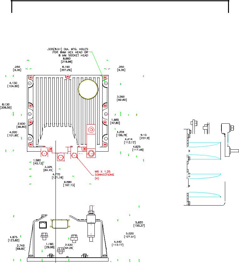
Section 3.2 Outline: SX-3 and SR-3 Package Size |
|
|
|
|
|
|
|
|
|
|
|
|
|
|
|
|
|
|
|
|
|
|
|
|
|
|
|
|
|
|
|
|||||||||||||||||||||||||||||||||||||||||||||||||||||||
|
|
|
|
|
|
|
|
|
|
|
|
|
|
|
|
|
|
|
|
|
|
|
|
|
|
|
|
|
|
|
|
|
|
|
|
|
|
|
|
|
|
|
|
|
|
|
|
|
|
|
|
|
|
|
|
|
|
|
|
|
|
|
|
|
|
|
|
|
|
|
|
|
|
|
|
|
|
|
|
|
|
|
|
|
|
|
|
|
|
|
|
|
|
|
|
|
|
|
|
|
|
|
|
|
|
|
|
|
|
|
|
|
|
|
|
|
|
|
|
|
|
|
|
|
|
|
|
|
|
|
|
|
|
|
|
|
|
|
|
|
|
|
|
|
|
|
|
|
|
|
|
|
|
|
|
|
|
|
|
|
|
|
|
|
|
|
|
|
|
|
|
|
|
|
|
|
|
|
|
|
|
|
|
|
|
|
|
|
|
|
|
|
|
|
|
|
|
|
|
|
|
|
|
|
|
|
|
|
|
|
|
|
|
|
|
|
|
|
|
|
|
|
|
|
|
|
|
|
|
|
|
|
|
|
|
|
|
|
|
|
|
|
|
|
|
|
|
|
|
|
|
|
|
|
|
|
|
|
|
|
|
|
|
|
|
|
|
|
|
|
|
|
|
|
|
|
|
|
|
|
|
|
|
|
|
|
|
|
|
|
|
|
|
|
|
|
|
|
|
|
|
|
|
|
|
|
|
|
|
|
|
|
|
|
|
|
|
|
|
|
|
|
|
|
|
|
|
|
|
|
|
|
|
|
|
|
|
|
|
|
|
|
|
|
|
|
|
|
|
|
|
|
|
|
|
|
|
|
|
|
|
|
|
|
|
|
|
|
|
|
|
|
|
|
|
|
|
|
|
|
|
|
|
|
|
|
|
|
|
|
|
|
|
|
|
|
|
|
|
|
|
|
|
|
|
|
|
|
|
|
|
|
|
|
|
|
|
|
|
|
|
|
|
|
|
|
|
|
|
|
|
|
|
|
|
|
|
|
|
|
|
|
|
|
|
|
|
|
|
|
|
|
|
|
|
|
|
|
|
|
|
|
|
|
|
|
|
|
|
|
|
|
|
|
|
|
|
|
|
|
|
|
|
|
|
|
|
|
|
|
|
|
|
|
|
|
|
|
|
|
|
|
|
|
|
|
|
|
|
|
|
|
|
|
|
|
|
|
|
|
|
|
|
|
|
|
|
|
|
|
|
|
|
|
|
|
|
|
|
|
|
|
|
|
|
|
|
|
|
|
|
|
|
|
|
|
|
|
|
|
|
|
|
|
|
|
|
|
|
|
|
|
|
|
|
|
|
|
|
|
|
|
|
|
|
|
|
|
|
|
|
|
|
|
|
|
|
|
|
|
|
|
|
|
|
|
|
|
|
|
|
|
|
|
|
|
|
|
|
|
|
|
|
|
|
|
|
|
|
|
|
|
|
|
|
|
|
|
|
|
|
|
|
|
|
|
|
|
|
|
|
|
|
|
|
|
|
|
|
|
|
|
|
|
|
|
|
|
|
|
|
|
|
|
|
|
|
|
|
|
|
|
|
|
|
|
|
|
|
|
|
|
|
|
|
|
|
|
|
|
|
|
|
|
|
|
|
|
|
|
|
|
|
|
|
|
|
|
|
|
|
|
|
|
|
|
|
|
|
|
|
|
|
|
|
|
|
|
|
|
|
|
|
|
|
|
|
|
|
|
|
|
|
|
|
|
|
|
|
|
|
|
|
|
|
|
|
|
|
|
|
|
|
|
|
|
|
|
|
|
|
|
|
|
|
|
|
|
|
|
|
|
|
|
|
|
|
|
|
|
|
|
|
|
|
|
|
|
|
|
|
|
|
|
|
|
|
|
|
|
|
|
|
|
|
|
|
|
|
|
|
|
|
|
|
|
|
|
|
|
|
|
|
|
|
|
|
|
|
|
|
|
|
|
|
|
|
|
|
|
|
|
|
|
|
|
|
|
|
|
|
|
|
|
|
|
|
|
|
|
|
|
|
|
|
|
|
|
|
|
|
|
|
|
|
|
|
|
|
|
|
|
|
|
|
|
|
|
|
|
|
|
|
|
|
|
|
|
|
|
|
|
|
|
|
|
|
|
|
|
|
|
|
|
|
|
|
|
|
|
|
|
|
|
|
|
|
|
|
|
|
|
|
|
|
|
|
|
|
|
|
|
|
|
|
|
|
|
|
|
|
|
|
|
|
|
|
|
|
|
|
|
|
|
|
|
|
|
|
|
|
|
|
|
|
|
|
|
|
|
|
|
|
|
|
|
|
|
|
|
|
|
|
|
|
|
|
|
|
|
|
|
|
|
|
|
|
|
|
|
|
|
|
|
|
|
|
|
|
|
|
|
|
|
|
|
|
|
|
|
|
|
|
|
|
|
|
|
|
|
|
|
|
|
|
|
|
|
|
|
|
|
|
|
|
|
|
|
|
|
|
|
|
|
|
|
|
|
|
|
|
|
|
|
|
|
|
|
|
|
|
|
|
|
|
|
|
|
|
|
|
|
|
|
|
|
|
|
|
|
|
|
|
|
|
|
|
|
|
|
|
|
|
|
|
|
|
|
|
|
|
|
|
|
|
|
|
|
|
|
|
|
|
|
|
|
|
|
|
|
|
|
|
|
|
|
|
|
|
|
|
|
|
|
|
|
|
|
|
|
|
|
|
|
|
|
|
|
|
|
|
|
|
|
|
|
|
|
|
|
|
|
|
|
|
|
|
|
|
|
|
|
|
|
|
|
|
|
|
|
|
|
|
|
|
|
|
|
|
|
|
|
|
|
|
|
|
|
|
|
|
|
|
|
|
|
|
|
|
|
|
|
|
|
|
|
|
|
|
|
|
|
|
|
|
|
|
|
|
|
|
|
|
|
|
|
|
|
|
|
|
|
|
|
|
|
|
|
|
|
|
|
|
|
|
|
|
|
|
|
|
|
|
|
|
|
|
|
|
|
|
|
|
|
|
|
|
|
|
|
|
|
|
|
|
|
|
|
|
|
|
|
|
|
|
|
|
|
|
|
|
|
|
|
|
|
|
|
|
|
|
|
|
|
|
|
|
|
|
|
|
|
|
|
|
|
|
|
|
|
|
|
|
|
|
|
|
|
|
|
|
|
|
|
|
|
|
|
|
|
|
|
|
|
|
|
|
|
|
|
|
|
|
|
|
|
|
|
|
|
|
|
|
|
|
|
|
|
|
|
|
|
|
|
|
|
|
|
|
|
|
|
|
|
|
|
|
|
|
|
|
|
|
|
|
|
|
|
|
|
|
|
|
|
|
|
|
|
|
|
|
|
|
|
|
|
|
|
|
|
|
|
|
|
|
|
|
|
|
|
|
|
|
|
|
|
|
|
|
|
|
|
|
|
|
|
|
|
|
|
|
|
|
|
|
|
|
|
|
|
|
|
|
|
|
|
|
|
|
|
|
|
|
|
|
|
|
|
|
|
|
|
|
|
|
|
|
|
|
|
|
|
|
|
|
|
|
|
|
|
|
|
|
|
|
|
|
|
|
|
|
|
|
|
|
|
|
|
|
|
|
|
|
|
|
|
|
|
|
|
|
|
|
|
|
|
|
|
|
|
|
|
|
|
|
|
|
|
|
|
|
|
|
|
|
|
|
|
|
|
|
|
|
|
|
|
|
|
|
|
|
|
|
|
|
|
|
|
|
|
|
|
|
|
|
|
|
|
|
|
|
|
|
|
|
|
|
|
|
|
|
|
|
|
|
|
|
|
|
|
|
|
|
|
|
|
|
|
|
|
|
|
|
|
|
|
|
|
|
|
|
|
|
|
|
|
|
|
|
|
|
|
|
|
|
|
|
|
|
|
|
|
|
|
|
|
|
|
|
|
|
|
|
|
|
|
|
|
|
|
|
|
|
|
|
|
|
|
|
|
|
|
|
|
|
|
|
|
|
|
|
|
|
|
|
|
|
|
|
|
|
|
|
|
|
|
|
|
|
|
|
|
|
|
|
|
|
|
|
|
|
|
|
|
|
|
|
|
|
|
|
|
|
|
|
|
|
|
|
|
|
|
|
|
|
|
|
|
|
|
|
|
|
|
|
|
|
|
|
|
|
|
|
|
|
|
|
|
|
|
|
|
|
|
|
|
|
|
|
|
|
|
|
|
|
|
|
|
|
|
|
|
|
|
|
|
|
|
|
|
|
|
|
|
|
|
|
|
|
|
|
|
|
|
|
|
|
|
|
|
|
|
|
|
|
|
|
|
|
|
|
|
|
|
|
|
|
|
|
|
|
|
|
|
|
|
|
|
|
|
|
|
|
|
|
|
|
|
|
|
|
|
|
|
|
|
|
|
|
|
|
|
|
|
|
|
|
|
|
|
|
|
|
|
|
|
|
|
|
|
|
|
|
|
|
|
|
|
|
|
|
|
|
|
|
|
|
|
|
|
|
|
|
|
|
|
|
|
|
|
|
|
|
|
|
|
|
|
|
|
|
|
|
|
|
|
|
|
|
|
|
|
|
|
|
|
|
|
|
|
|
|
|
|
|
|
|
|
|
|
|
|
|
|
|
|
|
|
|
|
|
|
|
|
|
|
|
|
|
|
|
|
|
|
|
|
|
|
|
|
|
|
|
|
|
|
|
|
|
|
|
|
|
|
|
|
|
|
|
|
|
|
|
|
|
|
|
|
|
|
|
|
|
|
|
|
|
|
|
|
|
|
|
|
|
|
|
|
|
|
|
|
|
|
|
|
|
|
|
|
|
|
|
|
|
|
|
|
|
|
|
|
|
|
|
|
|
|
|
|
|
|
|
|
|
|
|
|
|
|
|
|
|
|
|
|
|
|
|
|
|
|
|
|
|
|
|
|
|
|
|
|
|
|
|
|
|
|
|
|
|
|
|
|
|
|
|
|
|
|
|
|
|
|
|
|
|
|
|
|
|
|
|
|
|
|
|
|
|
|
|
|
|
|
|
|
|
|
|
|
|
|
|
|
|
|
|
|
|
|
|
|
|
|
|
|
|
|
|
|
|
|
|
|
|
|
|
|
|
|
|
|
|
|
|
|
|
|
|
|
|
|
|
|
|
|
|
|
|
|
|
|
|
|
|
|
|
|
|
|
|
|
|
|
|
|
|
|
|
|
|
|
|
|
|
|
|
|
|
|
|
|
|
|
|
|
|
|
|
|
|
|
|
|
|
|
|
|
|
|
|
|
|
|
|
|
|
|
|
|
|
|
|
|
|
|
|
|
|
|
|
|
|
|
|
|
|
|
|
|
|
|
|
|
|
|
|
|
|
|
|
|
|
|
|
|
|
|
|
|
|
|
|
|
|
|
|
|
|
|
|
|
|
|
|
|
|
|
|
|
|
|
|
|
|
|
|
|
|
|
|
|
|
|
|
|
|
|
|
|
|
|
|
|
|
|
|
|
|
|
|
|
|
|
|
|
|
|
|
|
|
|
|
|
|
|
|
|
|
|
|
|
|
|
|
|
|
|
|
|
|
|
|
|
|
|
|
|
|
|
|
|
|
|
|
|
|
|
|
|
|
|
|
|
|
|
|
|
|
|
|
|
|
|
|
|
|
|
|
|
|
|
|
|
|
|
|
|
|
|
|
|
|
|
|
|
|
|
|
|
|
|
|
|
|
|
|
|
|
|
|
|
|
|
|
|
|
|
|
|
|
|
|
|
|
|
|
|
|
|
|
|
|
|
|
|
|
|
|
|
|
|
|
|
|
|
|
|
|
|
|
|
|
|
|
|
|
|
|
|
|
|
|
|
|
|
|
|
|
|
|
|
|
|
|
|
|
|
|
|
|
|
|
|
|
|
|
|
|
|
|
|
|
|
|
|
|
|
|
|
|
|
|
|
|
|
|
|
|
|
|
|
|
|
|
|
|
|
|
|
|
|
|
|
|
|
|
|
|
|
|
|
|
|
|
|
|
|
|
|
|
|
|
|
|
|
|
|
|
|
|
|
|
|
|
|
|
|
|
|
|
|
|
|
|
|
|
|
|
|
|
|
|
|
|
|
|
|
|
|
|
|
|
|
|
|
|
|
|
|
|
|
|
|
|
|
|
|
|
|
|
|
|
|
|
|
|
|
|
|
|
|
|
|
|
|
|
|
|
|
|
|
|
|
|
|
|
|
|
|
|
|
|
|
|
|
|
|
|
|
|
|
|
|
|
|
|
|
|
|
|
|
|
|
|
|
|
|
|
|
|
|
|
|
|
|
|
|
|
|
|
|
|
|
|
|
|
|
|
|
|
|
|
|
|
|
|
|
|
|
|
|
|
|
|
|
|
|
|
|
|
|
|
|
|
|
|
|
|
|
|
|
|
|
|
|
|
|
|
|
|
|
|
|
|
|
|
|
|
|
|
|
|
|
|
|
|
|
|
|
|
|
|
|
|
|
|
|
|
|
|
|
|
|
|
|
|
|
|
|
|
|
|
|
|
|
|
|
|
|
|
|
|
|
|
|
|
|
|
|
|
|
|
|
|
|
|
|
|
|
|
|
|
|
|
|
|
|
|
|
|
|
|
|
|
|
|
|
|
|
|
|
|
|
|
|
|
|
|
|
|
|
|
|
|
|
|
|
|
|
|
|
|
|
|
|
|
|
|
|
|
|
|
|
|
|
|
|
|
|
|
|
|
|
|
|
|
|
|
|
|
|
|
|
|
|
|
|
|
|
|
|
|
|
|
|
|
|
|
|
|
|
|
|
|
|
|
|
|
|
|
|
|
|
|
|
|
|
|
|
|
|
|
|
|
|
|
|
|
|
|
|
|
|
|
|
|
|
|
|
|
|
|
|
|
|
|
|
|
|
|
|
|
|
|
|
|
|
|
|
|
|
|
|
|
|
|
|
|
|
|
|
|
|
|
|
|
|
|
|
|
|
|
|
|
|
|
|
|
|
|
|
|
|
|
|
|
|
|
|
|
|
|
|
|
|
|
|
|
|
|
|
|
|
|
|
|
|
|
|
|
|
|
|
|
|
|
|
|
|
|
|
|
|
|
|
|
|
|
|
|
|
|
|
|
|
|
|
|
|
|
|
|
|
|
|
|
|
|
|
|
|
|
|
|
|
|
|
|
|
|
|
|
|
|
|
|
|
|
|
|
|
|
|
|
|
|
|
|
|
|
|
|
|
|
|
|
|
|
|
|
|
|
|
|
|
|
|
|
|
|
|
|
|
|
|
|
|
|
|
|
|
|
|
|
|
|
|
|
|
|
|
|
|
|
|
|
|
|
|
|
|
|
|
|
|
|
|
|
|
|
|
|
|
|
|
|
|
|
|
|
|
|
|
|
|
|
|
|
|
|
|
|
|
|
|
|
|
|
|
|
|
|
|
|
|
|
|
|
|
|
|
|
|
|
|
|
|
|
|
|
|
|
|
|
|
|
|
|
|
|
|
|
|
|
|
|
|
|
|
|
|
|
|
|
|
|
|
|
|
|
|
|
|
|
|
|
|
|
|
|
|
|
|
|
|
|
|
|
|
|
|
|
|
|
|
|
|
|
|
|
|
|
|
|
|
|
|
|
|
|
|
|
|
|
|
|
|
|
|
|
|
|
|
|
|
|
|
|
|
|
|
|
|
|
|
|
|
|
|
|
|
|
|
|
|
|
|
|
|
|
|
|
|
|
|
|
|
|
|
|
|
|
|
|
|
|
|
|
|
|
|
|
|
|
|
|
|
|
|
|
|
|
|
|
|
|
|
|
|
|
|
|
|
|
|
|
|
|
|
|
|
|
|
|
|
|
|
|
|
|
|
|
|
|
|
|
|
|
|
|
|
|
|
|
|
|
|
|
|
|
|
|
|
|
|
|
|
|
|
|
|
|
|
|
|
|
|
|
|
|
|
|
|
|
|
|
|
|
|
|
|
|
|
|
|
|
|
|
|
|
|
|
|
|
|
|
|
|
|
|
|
|
|
|
|
|
|
|
|
|
|
|
|
|
|
|
|
|
|
|
|
|
|
|
|
|
|
|
|
|
|
|
|
|
|
|
|
|
|
|
|
|
|
|
|
|
|
|
|
|
|
|
|
|
|
|
|
|
|
|
|
|
|
|
|
|
|
|
|
|
|
|
|
|
|
|
|
|
|
|
|
|
|
|
|
|
|
|
|
|
|
|
|
|
|
|
|
|
|
|
|
|
|
|
|
|
|
|
|
|
|
|
|
|
|
|
|
|
|
|
|
|
|
|
|
|
|
|
|
|
|
|
|
|
|
|
|
|
|
|
|
|
|
|
|
|
|
|
|
|
|
|
|
|
|
|
|
|
|
|
|
|
|
|
|
|
|
|
|
|
|
|
|
|
|
|
|
|
|
|
|
|
|
|
|
|
|
|
|
|
|
|
|
|
|
|
|
|
|
|
|
|
|
|
|
|
|
|
|
|
|
|
|
|
|
|
|
|
|
|
|
|
|
|
|
|
|
|
|
|
|
|
|
|
|
|
|
|
|
|
|
|
|
|
|
|
|
|
|
|
|
|
|
|
|
|
|
|
|
|
|
|
|
|
|
|
|
|
|
|
|
|
|
|
|
|
|
|
|
|
|
|
|
|
|
|
|
|
|
|
|
|
|
|
|
|
|
|
|
|
|
|
|
|
|
|
|
|
|
|
|
|
|
|
|
|
|
|
|
|
|
|
|
|
|
|
|
|
|
|
|
|
|
|
|
|
|
|
|
|
|
|
|
|
|
|
|
|
|
|
|
|
|
|
|
|
|
|
|
|
|
|
|
|
|
|
|
|
|
|
|
|
|
|
|
|
|
|
|
|
|
|
|
|
|
|
|
|
|
|
|
|
|
|
|
|
|
|
|
|
|
|
|
|
|
|
|
|
|
|
|
|
|
|
|
|
|
|
|
|
|
|
|
|
|
|
|
|
|
|
|
|
|
|
|
|
|
|
|
|
|
|
|
|
|
|
|
|
|
|
|
|
|
|
|
|
|
|
|
|
|
|
|
|
|
|
|
|
|
|
|
|
|
|
|
|
|
|
|
|
|
|
|
|
|
|
|
|
|
|
|
|
|
|
|
|
|
|
|
|
|
|
|
|
|
|
|
|
|
|
|
|
|
|
|
|
|
|
|
|
|
|
|
|
|
|
|
|
|
|
|
|
|
|
|
|
|
|
|
|
|
|
|
|
|
|
|
|
|
|
|
|
|
|
|
|
|
|
|
|
|
|
|
|
|
|
|
|
|
|
|
|
|
|
|
|
|
|
|
|
|
|
|
|
|
|
|
|
|
|
|
|
|
|
|
|
|
|
|
|
|
|
|
|
|
|
|
|
|
|
|
|
|
|
|
|
|
|
|
|
|
|
|
|
|
|
|
|
|
|
|
|
|
|
|
|
|
|
|
|
|
|
|
|
|
|
|
|
|
|
|
|
|
|
|
|
|
|
|
|
|
|
|
|
|
|
|
|
|
|
|
|
|
|
|
|
|
|
|
|
|
|
|
|
|
|
|
|
|
|
|
|
|
|
|
|
|
|
|
|
|
|
|
|
|
|
|
|
|
|
|
|
|
|
|
|
|
|
|
|
|
|
|
|
|
|
|
|
|
|
|
|
|
|
|
|
|
|
|
|
|
|
|
|
|
|
|
|
|
|
|
|
|
|
|
|
|
|
|
|
|
|
|
|
|
|
|
|
|
|
|
|
|
|
|
|
|
|
|
|
|
|
|
|
|
|
|
|
|
|
|
|
|
|
|
|
|
|
|
|
|
|
|
|
|
|
|
|
|
|
|
|
|
|
|
|
|
|
|
|
|
|
|
|
|
|
|
|
|
|
|
|
|
|
|
|
|
|
|
|
|
|
|
|
|
|
|
|
|
|
|
|
|
|
|
|
|
|
|
|
|
|
|
|
|
|
|
|
|
|
|
|
|
|
|
|
|
|
|
|
|
|
|
|
|
|
|
|
|
|
|
|
|
|
|
|
|
|
|
|
|
|
|
|
|
|
|
|
|
|
|
|
|
|
|
|
|
|
|
|
|
|
|
|
|
|
|
|
|
|
|
|
|
|
|
|
|
|
|
|
|
|
|
|
|
|
|
|
|
|
|
|
|
|
|
|
|
|
|
|
|
|
|
|
|
|
|
|
|
|
|
|
|
|
|
|
|
|
|
|
|
|
|
|
|
|
|
|
|
|
|
|
|
|
|
|
|
|
|
|
|
|
|
|
|
|
|
|
|
|
|
|
|
|
|
|
|
|
|
|
|
|
|
|
|
|
|
|
|
|
|
|
|
|
|
|
|
|
|
|
|
|
|
|
|
|
|
|
|
|
|
|
|
|
|
|
|
|
|
|
|
|
|
|
|
|
|
|
|
|
|
|
|
|
|
|
|
|
|
|
|
|
|
|
|
|
|
|
|
|
|
|
|
|
|
|
|
|
|
|
|
|
|
|
|
|
|
|
|
|
|
|
|
|
|
|
|
|
|
|
|
|
|
|
|
|
|
|
|
|
|
|
|
|
|
|
|
|
|
|
|
|
|
|
|
|
|
|
|
|
|
|
|
|
|
|
|
|
|
|
|
|
|
|
|
|
|
|
|
|
|
|
|
|
|
|
|
|
|
|
|
|
|
|
|
|
|
|
|
|
|
|
|
|
|
|
|
|
|
|
|
|
|
|
|
|
|
|
|
|
|
|
|
|
|
|
|
|
|
|
|
|
|
|
|
|
|
|
|
|
|
|
|
|
|
|
|
|
|
|
|
|
|
|
|
|
|
|
|
|
|
|
|
|
|
|
|
|
|
|
|
|
|
|
|
|
|
|
|
|
|
|
|
|
|
|
|
|
|
|
|
|
|
|
|
|
|
|
|
|
|
|
|
|
|
|
|
|
|
|
|
|
|
|
|
|
|
|
|
|
|
|
|
|
|
|
|
|
|
|
|
|
|
|
|
|
|
|
|
|
|
|
|
|
|
|
|
|
|
|
|
|
|
|
|
|
|
|
|
|
|
|
|
|
|
|
|
|
|
|
|
|
|
|
|
|
|
|
|
|
|
|
|
|
|
|
|
|
|
|
|
|
|
|
|
|
|
|
|
|
|
|
|
|
|
|
|
|
|
|
|
|
|
|
|
|
|
|
|
|
|
|
|
|
|
|
|
|
|
|
|
|
|
|
|
|
|
|
|
|
|
|
|
|
|
|
|
|
|
|
|
|
|
|
|
|
|
|
|
|
|
|
|
|
|
|
|
|
|
|
|
|
|
|
|
|
|
|
|
|
|
|
|
|
|
|
|
|
|
|
|
|
|
|
|
|
|
|
|
|
|
|
|
|
|
|
|
|
|
|
|
|
|
|
|
|
|
|
|
|
|
|
|
|
|
|
|
|
|
|
|
|
|
|
|
|
|
|
|
|
|
|
|
|
|
|
|
|
|
|
|
|
|
|
|
|
|
|
|
|
|
|
|
|
|
|
|
|
|
|
|
|
|
|
|
|
|
|
|
|
|
|
|
|
|
|
|
|
|
|
|
|
|
|
|
|
|
|
|
|
|
|
|
|
|
|
|
|
|
|
|
|
|
|
|
|
|
|
|
|
|
|
|
|
|
|
|
|
|
|
|
|
|
|
|
|
|
|
|
|
|
|
|
|
|
|
|
|
|
|
|
|
|
|
|
|
|
|
|
|
|
|
|
|
|
|
|
|
|
|
|
|
|
|
|
|
|
|
|
|
|
|
|
|
|
|
|
|
|
|
|
|
|
|
|
|
|
|
|
|
|
|
|
|
|
|
|
|
|
|
|
|
|
|
|
|
|
|
|
|
|
|
|
|
|
|
|
|
|
|
|
|
|
|
|
|
|
|
|
|
|
|
|
|
|
|
|
|
|
|
|
|
|
|
|
|
|
|
|
|
|
|
|
|
|
|
|
|
|
|
|
|
|
|
|
|
|
|
|
|
|
|
|
|
|
|
|
|
|
|
|
|
|
|
|
|
|
|
|
|
|
|
|
|
|
|
|
|
|
|
|
|
|
|
|
|
|
|
|
|
|
|
|
|
|
|
|
|
|
|
|
|
|
|
|
|
|
|
|
|
|
|
|
|
|
|
|
|
|
|
|
|
|
|
|
|
|
|
|
|
|
|
|
|
|
|
|
|
|
|
|
|
|
|
|
|
|
|
|
|
|
|
|
|
|
|
|
|
|
|
|
|
|
|
|
|
|
|
|
|
|
|
|
|
|
|
|
|
|
|
|
|
|
|
|
|
|
|
|
|
|
|
|
|
|
|
|
|
|
|
|
|
|
|
|
|
|
|
|
|
|
|
|
|
|
|
|
|
|
|
|
|
|
|
|
|
|
|
|
|
|
|
|
|
|
|
|
|
|
|
|
|
|
|
|
|
|
|
|
|
|
|
|
|
|
|
|
|
|
|
|
|
|
|
|
|
|
|
|
|
|
|
|
|
|
|
|
|
|
|
|
|
|
|
|
|
|
|
|
|
|
|
|
|
|
|
|
|
|
|
|
|
|
|
|
|
|
|
|
|
|
|
|
|
|
|
|
|
|
|
|
|
|
|
|
|
|
|
|
|
|
|
|
|
|
|
|
|
|
|
|
|
|
|
|
|
|
|
|
|
|
|
|
|
|
|
|
|
|
|
|
|
|
|
|
|
|
|
|
|
|
|
|
|
|
|
|
|
|
|
|
|
|
|
|
|
|
|
|
|
|
|
|
|
|
|
|
|
|
|
|
|
|
|
|
|
|
|
|
|
|
|
|
|
|
|
|
|
|
|
|
|
|
|
|
|
|
|
|
|
|
|
|
|
|
|
|
|
|
|
|
|
|
|
|
|
|
|
|
|
|
|
|
|
|
|
|
|
|
|
|
|
|
|
|
|
|
|
|
|
|
|
|
|
|
|
|
|
|
|
|
|
|
|
|
|
|
|
|
|
|
|
|
|
|
|
|
|
|
|
|
|
|
|
|
|
|
|
|
|
|
|
|
|
|
|
|
|
|
|
|
|
|
|
|
|
|
|
|
|
|
|
|
|
|
|
|
|
|
|
|
|
|
|
|
|
|
|
|
|
|
|
|
|
|
|
|
|
|
|
|
|
|
|
|
|
|
|
|
|
|
|
|
|
|
|
|
|
|
|
|
|
|
|
|
|
|
|
|
|
|
|
|
|
|
|
|
|
|
|
|
|
|
|
|
|
|
|
|
|
|
|
|
|
|
|
|
|
|
|
|
|
|
|
|
|
|
|
|
|
|
|
|
|
|
|
|
|
|
|
|
|
|
|
|
|
|
|
|
|
|
|
|
|
|
|
|
|
|
|
|
|
|
|
|
|
|
|
|
|
|
|
|
|
|
|
|
|
|
|
|
|
|
|
|
|
|
|
|
|
|
|
|
|
|
|
|
|
|
|
|
|
|
|
|
|
|
|
|
|
|
|
|
|
|
|
|
|
|
|
|
|
|
|
|
|
|
|
|
|
|
|
|
|
|
|
|
|
|
|
|
|
|
|
|
|
|
|
|
|
|
|
|
|
|
|
|
|
|
|
|
|
|
|
|
|
|
|
|
|
|
|
|
|
|
|
|
|
|
|
|
|
|
|
|
|
|
|
|
|
|
|
|
|
|
|
|
|
January 2000

FU512 P2 |
KEY SWITCH |
P1 |
|
|
SP |
|
P5 |
L |
|
|
|
FU7 TO ACCESSORIES |
|
|
|
24 |
|
|
60 |
|
BRAKE SW.
SEAT SW. |
START SW. |
FORWARD SW. |
REVERSE SW. |
ELEMENTARY DRAWING FOR
SEPARATELY EXCITED DUAL MOTOR PROPORTIONING CONTROLLERS WITH SOLID-STATE REGENERATIVE BRAKING
FU6 |
P3 |
P4 |
|
|
|
|
|
|
|
|
15 6 |
8 |
|
|
|
|
|
|
|
|
10 7 |
||||
|
12-1 |
|
|
|
|
|
|
|
|
|||
|
10 |
|
|
|
|
|
|
|
12-1 |
|
|
PLUG PY |
|
|
|
|
|
|
|
|
|
|
CONNECTIONS |
||
|
|
|
|
|
|
|
|
|
|
|
|
|
|
PY7 |
|
|
|
|
|
|
P15 |
OSCILLATOR CARD |
|
|
PY7 |
|
PY12 P18 P1 P17 |
P2 P6 |
P3 |
P4 |
P5 |
|
P16 |
RIGHT CONTROL |
P1 P2 P6 |
P3 P4 |
P5 PY12 |
|
|
PY10 |
OSCILLATOR CARD |
P7 |
P10 |
P9 |
P12 |
P8 P21 P16 P15 |
P10 P7 |
P12 P13 P18 |
P11 PY10 |
||
|
PY11 |
LEFT CONTROL |
|
|
|
|
|
|
|
|
PY11 |
|
|
PLUG PY |
|
|
|
|
|
|
|
25 |
|
|
|
CONNECTIONS |
|
|
29 |
50 |
30 |
66 |
65 |
|
|
|
||
|
|
|
|
|
|
|
|
|||||
|
|
|
|
|
|
|
|
PMT ENABLE OUTPUT |
|
|
|
|
LINE |
FU1 3 |
|
|
|
|
|
|
AUTO REGENERATIVE |
|
|
|
|
|
|
|
|
|
|
|
BRAKING ENABLE |
|
|
|
||
|
|
|
|
|
|
|
|
STEER PUMP |
|
|
|
|
|
|
|
|
|
|
|
|
CONTACTOR DRIVER |
|
|
|
|
|
|
|
|
|
5 |
|
|
|
|
ACC POT |
STEER ANGLE |
|
REGEN OUTPUT |
||
|
|
|
|
2 |
|
|
|
|
|
POT |
|
|
SIGNAL |
||
|
|
|
|
|
|
|
|
|
|
|
|
||||
|
|
FU2 |
|
|
|
|
|
|
|
|
|
|
BDI INTERRUPT |
||
|
|
|
|
|
|
|
|
|
|
|
|
|
|||
|
+ |
FU4 |
|
|
|
|
|
|
13A |
|
|
|
|
|
|
|
|
|
|
|
|
|
|
|
|
|
|
|
|||
|
|
A1 |
|
43 |
|
|
|
|
|
|
|
|
|
|
|
|
|
|
|
|
|
|
|
|
|
|
|
|
|
|
|
|
|
|
P TMM7 |
A1 |
|
|
|
|
|
|
|
|
|
|
|
|
- |
A2 |
88 |
|
|
|
|
|
|
|
|
|
A1 |
|
|
|
|
|
F1 |
|
A1 |
ARMATURE |
|
|
|
|
ARMATURE |
||||
|
S1 |
TMM7 |
POS |
A1 |
FIELD |
POS |
A1 |
F1 |
FIELD |
||||||
|
|
A2 |
A2 |
||||||||||||
|
|
SP |
POWER |
|
|
|
|
POWER CONNECTIONS |
|
|
|
||||
|
|
|
|
|
CONNECTIONS |
|
|
|
|
|
|
|
|||
|
|
|
89 |
|
|
|
|
|
RIGHT CONTROL |
|
|
|
|||
|
|
|
A2 |
LEFT CONTROL |
|
|
|
|
|
|
|||||
|
|
|
|
|
|
|
|
|
|
|
|
||||
|
|
|
|
NEG |
A2 |
F2 |
|
|
|
NEG |
A2 |
F2 |
|
|
|
2000January |
|
S2 |
|
|
|
|
|
|
|
|
|
|
|
|
|
|
P |
SP |
|
|
|
|
|
|
|
|
|
|
|
|
|
|
|
|
|
|
|
|
|
|
|
|
|
|
|
|
|
Elementary Traction 3.3 Section |
ELEMENTARY DRAWINGS, OUTLINE CONTROL TRANSISTOR SX |
|
INPUTS/OUTPUTS AND DRAWINGS |
13 Page
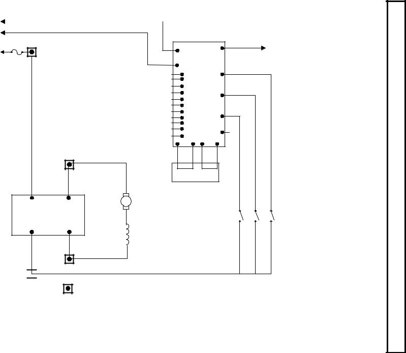
10
KEY SW. |
|
|
12-1 |
||
FU6 |
||
|
|
FU2 |
|
|
50 |
TO TRACTION |
|
|
10 |
PL2-10 |
||
LINE |
P |
2 |
|
||
|
|
|
|||
CONTACTOR 5A |
|
|
|
|
|
A1
P A1
PUMP CONTROL
POWER CONNECTION
N A2
A2
N
BATT (-)


|
1 |
|
PL2 |
|
|
STATUS CODE 93 INPUT |
3 |
|
12 |
||
2-SX |
PLUGCONTROL |
||||
STATUS CODE 93 INPUT |
4 |
|
|||
STATUS CODE 94 INPUT |
5 |
|
|
|
|
STATUS CODE 94 INPUT |
6 |
|
|
19 |
|
STATUS CODE 95 INPUT |
8 |
|
|
||
|
|
|
|||
STATUS CODE 95 INPUT |
9 |
|
|
|
|
STATUS CODE 92 INPUT |
15 |
|
|
20 |
|
STATUS CODE 90 INPUT |
16 |
|
|
||
|
|
|
|||
STATUS CODE 91 INPUT |
11 |
|
|
|
|
BRUSH WEAR OUTPUT |
13 |
|
|
21 |
|
14 |
|
|
|||
OVER TEMP OUTPUT |
|
|
|
PY7 PY12 PY10 PY11 |
PLUG PY
CONNECTIONS
A1 |
ARMATURE |
|
*
A2
FIELD *
13C
51
52
53
SPEED 3 |
SPEED 2 |
SPEED 1 |
* |
* |
* |
13C 13C 13C
POWER CONNECTION
* SUPPLIED BY CUSTOMER
2000 January
Elementary Pump 4.3 Section |
ELEMENTARY DRAWINGS, OUTLINE CONTROL TRANSISTOR SX |
|
INPUTS/OUTPUTS AND DRAWINGS |
14 Page

OUTLINE DRAWINGS, ELEMENTARY DRAWINGS AND INPUTS/OUTPUTS
|
SX TRANSISTOR CONTROL |
Page 15 |
|||||
|
Section 3.5. Traction and Pump Control Input and Output List |
|
|
||||
|
|
CONNECTIONS TO MAIN PLUG (23 PIN) AND "Y" PLUG (12 PIN) |
|||||
|
|
|
|
|
|
|
|
|
|
TRACTION |
PUMP |
|
|||
|
PIN |
INPUT/OUTPUT DESCRIPTION |
INPUT/OUTPUT DESCRIPTION |
|
|||
|
1 |
BATTERY VOLTS FROM BATTERY |
BATTERY VOLTS FROM BATTERY |
|
|||
|
2 |
BATTERY VOLTS FROM KEY |
BATTERY VOLTS FROM KEY |
|
|||
|
3 |
BATTERY VOLTS FROM START SWITCH |
STATUS CODE 93 INPUT |
|
|||
|
4 |
BATTERY VOLTS FROM FORWARD SWITCH |
STATUS CODE 93 INPUT |
|
|||
|
5 |
BATTERY VOLTS FROM REVERSE SWITCH |
STATUS CODE 94 INPUT |
|
|||
|
6 |
BATTERY VOLTS FROM SEAT SWITCH |
STATUS CODE 94 INPUT |
|
|||
|
7 |
ACCELERATOR INPUT VOLTAGE SIGNAL |
POTENTIOMETER INPUT VOLTAGE SIGNAL |
|
|||
|
8 |
STEER ANGLE POT NEGATIVE |
STATUS CODE 95 INPUT |
|
|||
|
9 |
STEER ANGLE POT +5 VOLTS SUPPLY |
STATUS CODE 95 INPUT |
|
|||
|
10 |
BDI INTERRUPT |
PUMP ENABLE SIGNAL 12VDC |
|
|||
|
11 |
PLUG/RGN OUTPUT SIGNAL +12V 1.0V=REGEN |
STATUS CODE 91 INPUT |
|
|||
|
12 |
STEER ANGLE INPUT VOLTAGE SIGNAL |
SPEED LIMIT #1 INPUT |
|
|||
|
13 |
RGN BRAKE POTENTIOMETER INPUT |
TMM1 BRUSHWEAR INDICATER OUTPUT |
|
|||
|
14 |
TMM BRUSHWEAR |
TMM1 OVER TEMPERATURE OUTPUT |
|
|||
|
15 |
IMOTOR OUT |
STATUS CODE 92 INPUT |
|
|||
|
16 |
MOTOR CURRENT COMPENSATION |
STATUS CODE 90 INPUT |
|
|||
|
17 |
LINE CONTACTOR DRIVER AND SUPPRESSION |
LINE CONTACTOR DRIVER |
|
|||
|
18 |
STEER PUMP CTR DRIVER AND SUPPRESSION |
1A CONTACTOR DRIVER |
|
|||
|
19 |
DASH DISPLAY + 5 VOLT SUPPLY |
SPEED LIMIT #2 INPUT |
|
|||
|
20 |
TMM OVERTEMP |
SPEED LIMIT #3 INPUT |
|
|||
|
21 |
NOT USED |
NOT USED |
|
|||
|
22 |
SERIAL RECEIVE / DASH DISPLAY |
SERIAL RECEIVE |
|
|||
|
23 |
SERIAL TRANSMIT / DASH DISPLAY |
SERIAL TRANSMIT |
|
|||
|
|
MOTOR PROPORTIONING "Y" PLUG |
PUMP "Y" PLUG |
|
|||
|
PIN |
INPUT/OUTPUT DESCRIPTION |
INPUT/OUTPUT DESCRIPTION |
|
|||
|
1 |
CLOCK (OUT) |
CLOCK (OUT) |
|
|||
|
2 |
DATA (OUT) |
DATA (OUT) |
|
|||
|
3 |
ENABLE (OUT) |
ENABLE (OUT) |
|
|||
|
4 |
NEGATIVE |
NEGATIVE |
|
|||
|
5 |
+5V SUPPLY |
+5V SUPPLY |
|
|||
|
6 |
CONT/STORE (IN) (HANDSET) |
CONT/STORE (IN) (HANDSET) |
|
|||
|
7 |
EXTERNAL JUMPER TO PY12 |
EXTERNAL JUMPER TO PY12 |
|
|||
|
8 |
VALUE |
VALUE |
|
|||
|
9 |
FUNCTION |
FUNCTION |
|
|||
|
10 |
EXTERNAL JUMPER TO PY11 |
EXTERNAL JUMPER TO PY11 |
|
|||
|
11 |
SERIAL RECEIVE / CONNECT TO P22 |
SERIAL RECEIVE / CONNECT TO P22 |
|
|||
|
12 |
SERIAL TRANSMIT / CONNECT TO P23 |
SERIAL TRANSMIT / CONNECT TO P23 |
|
|||
|
|
|
|
|
|
|
|
|
|
|
|
|
|
|
|
1 
 2
2 
 3
3 
 4
4 
 5
5 
 6
6
7 
 8
8 
 9
9 
 10
10 
 11
11 
 12
12
WIRE END VIEW "Y" PLUG
1 |
2 |
3 |
4 |
5 |
6 |
6 |
8 |
9 |
10 |
11 |
12 |
|
13 |
14 |
15 |
16 |
17 |
18 |
19 |
20 |
21 |
22 |
23 |
WIRE END VIEW - MAIN PLUG
January 2000

DIAGNOSTIC STATUS CODES
SX TRANSISTOR CONTROL Page 16
Section 4.0 TROUBLESHOOTING AND DIAGNOSTIC STATUS CODES
Section 4.1 General Maintenance Instructions
The transistor control, like all electrical apparatus, does have some thermal losses. The semiconductor junctions have finite temperature limits, above which these devices may be damaged. For these reasons, normal maintenance should guard against any action which will expose the components to excessive heat and/or those conditions which will reduce the heat dissipating ability of the control, such as restricting air flow.
The following Do’s and Don’t’s should be observed:
Any controls that will be applied in ambient temperatures over 100° F (40° C) should be brought to the attention of the vehicle manufacturer.
All external components having inductive coils must be filtered. Refer to vehicle manufacturer for specifications.
The wiring should not be directly steam cleaned. In dusty areas, blow low-pressure air over the control to remove dust. In oily or greasy areas, a mild solution of detergent or denatured alcohol can be used to wash the control, and then low-pressure air should be used to completely dry the control.
For the control to be most effective, it must be mounted against the frame of the vehicle. The metal vehicle frame, acting as an additional heat sink, will give improved vehicle performance by keeping the control package cooler. Apply a thin layer of heat-transfer grease (such as Dow Corning 340) between the control heat sink and the vehicle frame.
Control wire plugs and other exposed transistor control parts should be kept free of dirt and paint that might change the effective resistance between points.
CAUTION: The vehicle should not be plugged when the vehicle is jacked up and the drive wheels are in a free wheeling position. The higher motor speeds can create excessive voltages that can be harmful to the control.
Do not hipot (or megger) the control. Refer to control manufacturer before hipotting.
Use a lead-acid battery with the voltage and ampere hour rating specified for the vehicle. Follow normal battery maintenance procedures, recharging before 80 percent discharged with periodic equalizing charges.
Visual inspection of GE contactors contained in the traction and pump systems is recommended to occur during every
160 hours of vehicle operation. Inspection is recommended to verify that the contactors are not binding and that the tips are intact and free of contaminants.
GE does not recommend that any type of welding be performed on the vehicle after the installation of the control(s) in the vehicle. GE will not honor control failures during the warranty period when such failures are attributed to welding while the control is installed in the vehicle.
Section 4.2 Cable Routing and Separation
Electrical noise from cabling of various voltage levels can interfere with a microprocessor-based control system. To reduce this interference, GE recommends specific cable separation and routing practices, consistent with industry standards.
Section 4.2.1 Application Responsibility
The customer and customer’s representative are responsible for the mechanical and environmental locations of cables. They are also responsible for applying the level rules and cabling practices defined in this section. To help ensure a lower cost, noise-free installation, GE recommends early planning of cable routing that complies with these level separation rules.
On new installations, sufficient space should be allowed to efficiently arrange mechanical and electrical equipment.
On vehicle retrofits, level rules should be considered during the planning stages to help ensure correct application and a more trouble-free installation.
Section 4.2.2. Signal/PowerLevel Definitions
The signal/power carrying cables are categorized into four defining levels: low, high, medium power, and high power. Within those levels, signals can be further divided into classes.
Sections 4.2.2.a through 4.2.2.d define these levels and classes, with specific examples of each. Section 4.2.3 contains recommendations for separating the levels.
4.2.2.a Low-Level Signals (Level L)
Low-level signals are designated as level L. These consist of:
•Analog signals 0 through ±15 V
•Digital signals whose logic levels are less than 15 V DC
•4 – 20 mA current loops
•DC busses less than 15 V and 250 mA
The following are specific examples of level L signals used in drive equipment cabling:
January 2000

DIAGNOSTIC STATUS CODES
SX TRANSISTOR CONTROL |
Page 17 |
|
• |
Control common tie |
customer must apply the general guidelines (section |
• |
DC buses feeding sensitive analog or digital hardware |
4.2.3.a), outlined below. |
•All wiring connected to components associated with
|
sensitive analog hardware with less than 5V signals (for |
4.2.3.a General Cable Spacing |
• |
example, potentiometers and tachometers) |
|
Digital tachometers and resolvers |
The following general practices should be used for all |
|
• |
Dash display cabling |
levels of cabling: |
•RS-232 cabling
|
|
• |
All cables and wires of like signal levels and power |
|
Note: Signal inputs to analog and digital blocks should be |
• |
levels must be grouped together. |
||
run as shielded twisted-pair (for example, inputs from |
In general, different levels must run in separate wire |
|||
tachometers, potentiometers, and dash displays). |
|
bundles, as defined in the different classes, identified |
||
|
|
|
above. Intermixing cannot be allowed, unless noted by |
|
4.2.2.b High-Level Signals (Level H) |
• |
exception. |
||
|
|
Interconnecting wire runs should carry a level |
||
High-level signals are designated as level H. These signals |
• |
designation. |
||
consist of: |
If wires are the same level and same type signal, group |
|||
• |
|
|
those wires from one location to any other location |
|
Analog and digital signals greater than 15 V DC and |
|
together in multiconductor cables or bind them |
||
|
less than 250 mA |
• |
together with twine or zip-ties. |
|
|
|
When unlike signals must cross, cross them in 90° |
||
For example, switch inputs connected to battery volts are |
|
angles at a maximum spacing. Where it is not possible |
||
examples of level H signals used in drive equipment |
|
to maintain spacing, place a grounded steel barrier |
||
cabling. |
|
between unlike levels at the crossover point. |
||
4.2.2.c Medium-Power Signals (Level MP) |
4.2.4 Cabling for Vehicle Retrofits |
|||
Medium power signals are designated as level MP. These |
Reducing electrical noise on vehicle retrofits requires |
|||
signals consist of: |
careful planning. Lower and higher levels should never |
|||
• DC switching signals greater than 15 V |
encircle each other or run parallel for long distances. |
|||
It is practical to use existing wire runs or trays as long as |
||||
• Signals with currents greater than 250 mA and less than |
the level spacing (see section 4.2.2) can be maintained for |
|||
|
10A |
the full length of the run. |
||
The following are specific examples of level MP signals |
Existing cables are generally of high voltage potential and |
|||
noise producing. Therefore, route levels L and H in a path |
||||
used in drive equipment cabling: |
||||
separate from existing cables, whenever possible. |
||||
|
|
|||
• DC busses less than 10 A |
For level L wiring, use barriers in existing wire runs to |
|||
• Contactor coils less than 10 A |
minimize noise potential. |
|||
• Machine fields less than 10 A |
Do not loop level L signal wires around level H, level MP, or |
|||
4.2.2.d. High Power Signals (Level HP) |
HP wires. |
|||
|
|
|||
Power wiring is designated as level HP. This consists of DC |
4.2.5 RF Interference |
|||
|
|
|||
buses and motor wiring with currents greater than 10 A. |
To prevent radio frequency (RF) interference, care should |
|||
The following are specific examples of level HP signals |
be taken in routing power cables in the vicinity of radio- |
|||
used in drive equipment cabling: |
controlled devices. |
|||
•Motor armature loops
• DC outputs 10 A and above |
Section 4.2.6 Suppression |
•Motor field loops 10 A and above
4.2.3. Cable Spacing Guidelines |
Unless specifically noted otherwise, suppression (for |
|
example, a snubber) is required on all inductive devices |
||
Recommended spacing (or clearance) between cables (or |
controlled by an output. This suppression minimizes noise |
|
and prevents damage caused by electrical surges. |
||
wires) is dependent on the level of the wiring inside them. |
||
|
||
For correct level separation when installing cable, the |
|
January 2000
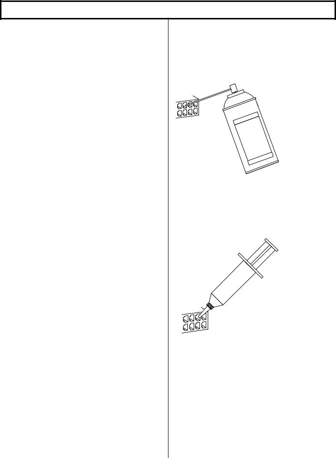
DIAGNOSTIC STATUS CODES
SX TRANSISTOR CONTROL
Section 4.3 Recommended Lubrication of Pins and Sockets Prior to Installation
Beginning in January of 1999, GE will implement the addition of a lubricant to all connections using pins and sockets on EV100/EV200 and Gen II products. Any connection made by GE to the A, B, X, Y, or Z plugs will have the lubricant NYE 760G added to prevent fretting of these connections during vehicle operation.
Fretting occurs during microscopic movement at the contact points of the connection. This movement exposes the base metal of the connector pin which, when oxygen is present, allows oxidation to occur. Sufficient build up of the oxidation can cause intermittent contact and intermittent vehicle operation. This can occur at any similar type of connection, whether at the control or in any associated vehicle wiring, and the resultant intermittent contact can provide the same fault indication as actual component failure.
The addition of the NYE 760G lubricant will prevent the oxidation process by eliminating the access of oxygen to the contact point. GE recommends the addition of this lubricant to the 12 pin and 23 pin plugs of all new Gen II controls at the time of their installation into a vehicle
When servicing existing vehicles exhibiting symptoms of intermittent mis-operation or shutdown by the GE control, GE recommends the addition of this lubricant to all 12 and 23 pin plugs, after proper cleaning of the connectors, as a preventative measure to insure fretting is not an issue before GE control replacement. Also, for long term reliable control operation, the plug terminals must be maintained per these instructions with the recommended contact cleaner and lubricant which provides a high degree of environmental and fretting protection.
New and re-manufactured control plugs are cleaned and lubricated prior to shipment from the factory. However, in applications where severe vibration or high temperature cycling and excessive humidity ( such as freezers ) are present, it is recommended that the plug terminals be cleaned and lubricated every year, per this instructions. In normal applications, plug maintenance should be performed every two years, unless intermittent problems arise with the plugs, requiring more immediate attention.
Warning: Do not use any other cleaners or lubricants other than the ones specified.
WARNING: Before conducting maintenance on the vehicle, jack up the drive wheels, disconnect the battery and discharge the capacitors. Consult the Operation and Service Manual for your particular vehicle for details on discharging the capacitors; this procedure differs between SCR and Transistor controls.
1.Disconnect plug from controller or mating plug.
Page 18
2.Locate the plug that contains the socket (female) terminals. Maintenance needs only to be performed on the plug containing the socket (female) type terminals. Reconnecting the plugs will lubricate the pin (male) terminals.
3. Clean each terminal using Chemtronics contact cleaner “Pow-R-WasH CZ “ as shown in Figure 1.
|
|
|
|
|
|
|
s |
|
|
|
|
|
|
|
|
|
c |
|
|
||
|
|
|
|
oni |
|
|
|
|
||
|
|
|
tr |
|
|
|
|
|
|
|
|
m |
|
|
|
|
|
|
|
||
he |
|
|
|
|
|
|
er |
|
|
|
C |
|
|
|
|
|
|
|
|
|
|
|
|
|
|
|
|
an |
|
|
||
|
|
|
|
|
le |
|
|
|
|
|
|
|
|
|
tc |
|
|
|
|
|
|
|
|
|
ac |
|
|
|
|
|
|
|
|
|
nt |
|
|
|
|
|
|
|
|
|
co |
|
|
|
C |
Z |
|
|
||
|
|
|
|
|
|
|
|
|||
|
|
- |
|
|
|
|||||
|
|
|
|
|
|
|
||||
|
|
|
RH |
|
||||||
|
|
|
|
-s |
|
|||||
|
|
|
|
wa |
|
|||||
|
|
|
|
|
|
|
|
W |
||
|
|
|
|
|
o |
|
|
|||
|
|
|
|
|
P |
|
|
|||
|
|
|
|
|
|
|
|
|
|
e |
|
|
|
|
|
|
|
|
|
an |
|
|
|
|
|
|
|
|
|
oz |
|
|
|
|
|
|
|
|
|
|
cir |
|
|
Figure 1
4. Lubricate each terminal using Nye 760G lubricant as shown in figure 2. Apply enough lubricant to each terminal opening to completely fill each opening to a depth of .125” minimum.
LUNye
B
RICA
N
TS
Figure 2
5.Reconnect plugs.
Reference |
|
Cleaner |
Chemtronics Pow-R-WasH CZ Contact |
|
Cleaner |
Lubricant |
Nye Lubricants NYOGEL 760G |
GE Plug Lub Kit |
Contains both above products: |
|
328A1777G1 |
January 2000

DIAGNOSTIC STATUS CODES
SX TRANSISTOR CONTROL |
Page 19 |
Section 4.4 General Troubleshooting Instructions |
|
Trouble-shooting the SX family of controls should be quick and easy when following the instructions outlined in the following status code instruction sheets.
If mis-operation of the vehicle occurs, a status code will be displayed on the Dash Display (for vehicles equipped with a Dash Display) or made available by plugging a Handset into the plug "Y" location, and then reading the status code.
Note: Status code numbers from 00 to 99 are traction control status codes. Status codes with the prefix 1 (101 to 199) are pump control status codes.
With the status code number, follow the procedures outlined in the status code instruction sheets to determine the problem.
Important Note: Due to the interaction of the logic card with all vehicle functions, almost any status code or control fault could be caused by the logic card. After all other status code procedures have been followed and no problem is found, the controller should then be replaced as the last option to correct the problem.
The same device designations have been maintained on different controls but the wire numbers may vary. Refer to the elementary and wiring diagrams for your specific control. The wire numbers shown on the elementary diagram will have identical numbers on the corresponding wiring diagrams for a specific vehicle, but these numbers may be different from the numbers referenced in this publication.
WARNING: Before trouble-shooting, jack up the drive wheels, disconnect the battery and discharge the capacitors. Reconnect the battery as needed for specific checks. Capacitors should be discharged by connecting a 200 ohm 2 watt resistor between the positive and negative terminals on the control panel.
Check resistance on R x 1000 scale from frame to power and control terminals. A resistance of less than 20,000 ohms can cause misleading symptoms. Resistance less than 1000 ohms should be corrected first.
Before proceeding, visually check for loose wiring, mis-aligned linkage to the accelerator switch, signs of overheating of components, etc.
Tools and test equipment required are: clip leads, volt-ohm meter (20,000 ohms per volt) and basic hand tools.
January 2000
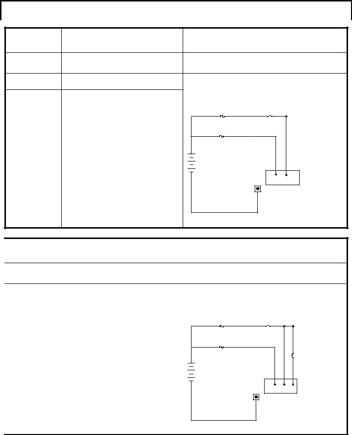
DIAGNOSTIC STATUS CODES
SX TRANSISTOR CONTROL |
Page 20 |
Section 4.5 Traction Control Codes |
|
TRACTION |
DESCRIPTION OF STATUS |
CAUSE OF STATUS INDICATION |
|
STATUS CODE |
|
|
|
NONE |
Segments do not illuminate on the |
No input voltage to the control card or the display unit. |
|
Dash Display and/or the Handset. |
|
|
|
MEMORY RECALL |
CORRECTIVE ACTIONS |
TROUBLE-SHOOTING DIAGRAM |
|
NO |
|||
Circuits valid |
SYMPTOM |
|
|
Display screen on Dash Display and/or Handset |
FU3 |
KEY |
|
for |
is blank. |
SWITCH |
|
|
|
|
|
Traction |
POSSIBLE CAUSE |
|
|
Controller |
Positive or negative control voltage is not |
FU5 |
|
|
present. |
|
|
•Insure that the key switch is closed and voltage is present between P1 & battery
+
negative (Power Terminal “NEG”). Also check for voltage between P2 and control negative.
Open circuit between control card AND the Dash |
- |
Display or Handset. |
P1 P2 |
• Check for an open circuit or loose connection |
NEG |
going from the control and the Dash Display or |
|
Handset. |
|
Defective Dash Display or Handset.
• Replace Dash Display or Handset.
TRACTION |
DESCRIPTION OF STATUS |
|
STATUS CODE |
|
|
-01 |
No seat switch or deadman switch |
|
input (no voltage to P6). |
||
MEMORY RECALL |
CORRECTIVE ACTIONS |
|
NO |
||
Circuits valid |
SYMPTOM |
|
Control will not operate. |
||
for |
POSSIBLE CAUSE |
|
Traction |
||
Mis-adjusted or defective seat or deadman |
||
Controller |
switch. |
|
|
• Check to see that the seat switch closes |
|
|
properly. |
|
|
Open circuit between battery positive and P6. |
|
|
• Check for loose connections or broken wires: |
|
|
− Between the seat switch and P6 |
|
|
− Between the key switch and the battery |
|
|
positive side of the seat switch. |
|
|
− Between the seat switch and P2. |
|
|
• On vehicles without a seat/deadman switch, |
|
|
check for a loose connection or broken wire |
|
|
from P2 and/or P6. |
|
|
|
CAUSE OF STATUS INDICATION
This status code will be displayed when P6 is less than 50% battery volts.
TROUBLE-SHOOTING DIAGRAM
|
KEY |
|
|
FU3 |
SWITCH |
|
|
|
|
|
|
FU5 |
|
|
SWITCH |
|
|
|
|
+ |
|
|
SEAT |
|
|
|
|
- |
|
|
|
|
P1 |
P2 |
P6 |
|
NEG |
|
|
January 2000
DIAGNOSTIC STATUS CODES
SX TRANSISTOR CONTROL Page 21
TRACTION |
DESCRIPTION OF STATUS |
CAUSE OF STATUS INDICATION |
STATUS CODE |
|
|
|
|
|
-02 |
Forward directional switch is closed on |
This status code will be displayed when P4 is greater |
initial power up. |
than 60% of battery voltage at initial key switch on. |
MEMORY RECALL |
CORRECTIVE ACTIONS |
|
NO |
||
|
||
|
SYMPTOM |
|
Circuits valid |
Control will not operate because of Static Return |
|
to Off (SRO) lock out. |
||
for |
POSSIBLE CAUSE |
|
Traction |
||
Forward directional switch is closed on initial |
||
Controller |
start up (i.e. closure of battery, key switch or |
|
|
seat switch). |
|
|
• Return directional switch lever to neutral and |
|
|
then return lever to forward position. |
Forward directional switch is welded closed or mis-adjusted to be held closed.
•Replace or adjust directional switch to insure that it opens when the directional switch is returned to neutral.
Short circuit between P3 and P4.
•Disconnect the wire from P4 and check for a short circuit between P3 and the wire that was connected to P4.
Defective control.
• Replace the controller unit.
TROUBLE-SHOOTING DIAGRAM
KEY
SWITCH
|
|
L |
SWITCHSEAT |
STARTSW. |
FORWARDSW. |
REVERSESW. |
|
|
|
|
|
|
|
P1 |
P17 |
P2 |
P6 |
P3 |
P4 |
P5 |
TRACTION |
DESCRIPTION OF STATUS |
|
STATUS CODE |
|
|
-03 |
Reverse directional switch is closed on |
|
initial power up. |
||
MEMORY RECALL |
CORRECTIVE ACTIONS |
|
NO |
||
|
||
|
SYMPTOM |
|
Circuits valid |
Control will not operate because of Static Return |
|
to Off (SRO) lock out. |
||
for |
POSSIBLE CAUSE |
|
Traction |
||
Reverse directional switch is closed on initial |
||
Controller |
start up (i.e. closure of battery, key switch or |
|
|
seat/deadman switch). |
|
|
• Return directional switch lever to neutral and |
|
|
then return lever to reverse position. |
Reverse directional switch is welded closed or mis-adjusted to be held closed.
•Replace or adjust directional switch to insure that it opens when the directional switch is returned to neutral.
Short circuit between P3 and P5.
•Disconnect the wire from P5 and check for a short circuit between P3 and the wire that was connected to P5.
Defective control. Replace the controller unit.
CAUSE OF STATUS INDICATION
This status code will be displayed when P5 is greater than 60% of battery voltage at initial key switch on.
TROUBLE-SHOOTING DIAGRAM
KEY
SWITCH
|
|
L |
SWITCHSEAT |
STARTSW. |
FORWARDSW. |
REVERSESW. |
|
|
|
|
|
|
|
P1 |
P17 |
P2 |
P6 |
P3 |
P4 |
P5 |
January 2000
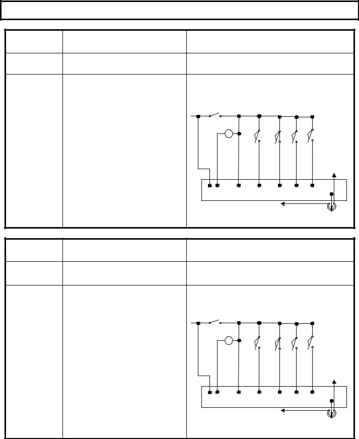
DIAGNOSTIC STATUS CODES
SX TRANSISTOR CONTROL Page 22
TRACTION |
DESCRIPTION OF STATUS |
|
STATUS CODE |
|
|
-05 |
Start switch fails to close. |
|
|
||
MEMORY RECALL |
CORRECTIVE ACTIONS |
|
NO |
||
|
||
|
SYMPTOM |
|
Circuits valid |
Control will not operate. |
|
|
||
for |
POSSIBLE CAUSE |
|
Traction |
Defective start switch circuit. |
|
• Check start switch to insure closure when |
||
Controller |
accelerator is depressed. |
|
|
• Check for open circuit or loose connections in |
|
|
wiring from brake switch to start switch and |
|
|
from P3 to start switch. |
Defective accelerator switch.
•Check accelerator switch potentiometer for proper operation and ohmic value.
CAUSE OF STATUS INDICATION
This status code will be displayed when P7 is less than 2.5 volts and P3 is less than 60% of battery volts.
TROUBLE-SHOOTING DIAGRAM
KEY
SWITCH
|
|
L |
SWITCHSEAT |
STARTSW. |
FORWARDSW. |
REVERSESW. |
|
|
|
|
|
|
|
|
|
|
|
|
|
|
|
|
NEG |
P1 |
P17 |
P2 |
P6 |
P3 |
P4 |
P5 |
P7 |
|
|
|
KEY SWITCH |
|
|
|
|
|
|
|
|
|
|
|
ACCPOT |
TRACTION |
DESCRIPTION OF STATUS |
|
STATUS CODE |
|
|
-06 |
Accelerator depressed with no |
|
direction selected. |
||
MEMORY RECALL |
CORRECTIVE ACTIONS |
|
NO |
||
|
||
|
SYMPTOM |
|
Circuits valid |
Control will not operate. |
|
|
||
for |
POSSIBLE CAUSE |
|
Traction |
Accelerator pedal is depressed before closing |
|
forward or reverse directional switch. |
||
Controller |
• Status code will disappear when directional |
|
|
switch is closed or when accelerator pedal is |
|
|
released. |
Defective directional switch
•Check forward or reverse switch to insure closure when direction is selected.
Open circuit between directional switch(es) and battery positive or between directional switch(es) and P4 or P5.
•Check all control wires and connections shown in Trouble Shooting Diagram.
CAUSE OF STATUS INDICATION
This status code will be displayed when P4 and P5 are less than 60% of battery volts, and P7 is less than 2.5 volts.
TROUBLE-SHOOTING DIAGRAM
KEY
SWITCH
|
|
L |
SWITCHSEAT |
STARTSW. |
FORWARDSW. |
REVERSESW. |
|
|
|
|
|
|
|
|
|
|
|
|
|
|
|
|
NEG |
P1 |
P17 |
P2 |
P6 |
P3 |
P4 |
P5 |
P7 |
|
|
|
KEY SWITCH |
|
|
|
|
|
|
|
|
|
|
|
ACCPOT |
January 2000
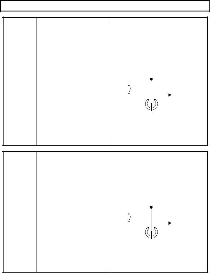
DIAGNOSTIC STATUS CODES
SX TRANSISTOR CONTROL Page 23
TRACTION |
DESCRIPTION OF STATUS |
CAUSE OF STATUS INDICATION |
||||||||
STATUS CODE |
|
|
|
|
|
|
|
|
|
|
|
|
|
|
|
|
|
|
|
||
-07 |
Accelerator input voltage too high on |
This status code will be displayed when the |
||||||||
power up after initial key switch |
accelerator input voltage at P7 is higher than 4.2 |
|||||||||
|
closure. |
volts, and a directional contactor is picked up. |
||||||||
MEMORY RECALL |
CORRECTIVE ACTIONS |
TROUBLE-SHOOTING DIAGRAM |
||||||||
NO |
||||||||||
|
|
|
|
|
|
|
|
|
||
|
SYMPTOM |
|
|
|
|
|
|
|
|
|
Circuits valid |
Control will not operate when accelerator pedal |
|
|
|
|
|
|
|
|
|
is depressed or status code -07 is displayed |
|
|
|
|
|
|
|
|
||
for |
then disappears when the vehicle starts to |
|
|
|
|
|
|
|
|
|
Traction |
accelerate. |
|
|
|
P7 |
|
|
|||
POSSIBLE CAUSE |
|
|
|
|
|
|||||
Controller |
Accelerator input mis-adjusted or defective. |
|
|
|
|
|
|
|
|
|
|
|
|
|
|
|
|
|
|||
|
• Input voltage at P7 should be less than 3.7 |
|
|
|
|
|
|
|
|
|
|
|
|
|
|
|
|
|
|
||
|
volts. Adjust or replace accelerator unit to |
|
|
KEY |
|
|
NEGATIVE |
|||
|
insure that the voltage at P7 will vary from 3.5 |
|
|
|
|
|||||
|
|
SWITCH |
|
|
||||||
|
volts to less than .5 volts when the pedal is |
|
|
|
|
|
|
|||
|
|
|
|
|
|
|
|
|
||
|
depressed. |
|
|
|
|
|
|
|
|
|
|
|
|
|
|
|
|
|
|
||
|
|
|
|
|
|
|
|
|
|
|
Open circuit between battery negative and P7 in accelerator input circuit.
• Check for broken wires or loose connections ACC POT or open potentiometer / voltage supply.
Short circuit from battery positive to wiring in accelerator input circuit.
•Disconnect wire from P7 and measure voltage at wire to negative. Should be zero volts for potentiometer type and less than 3.7 volts for solid state type accelerator input.
TRACTION |
DESCRIPTION OF STATUS |
CAUSE OF STATUS INDICATION |
|||||||
STATUS CODE |
|
|
|
|
|
|
|
|
|
|
|
|
|
|
|
|
|
||
-08 |
Accelerator input voltage too low on |
This status code will be displayed when the |
|||||||
power up after initial key switch |
accelerator input voltage at P7 is less than 3.0 volts, |
||||||||
|
closure. |
and any of the following connections are opened and |
|||||||
|
|
closed: battery plug or key switch. |
|||||||
MEMORY RECALL |
CORRECTIVE ACTIONS |
TROUBLE-SHOOTING DIAGRAM |
|||||||
NO |
|||||||||
|
|
|
|
|
|
|
|
||
|
SYMPTOM |
|
|
|
|
|
|
|
|
Circuits valid |
Control will not operate. |
|
|
|
P7 |
|
|
||
|
|
|
|
|
|
||||
for |
POSSIBLE CAUSE |
|
|
|
|
|
|
|
|
|
|
|
|
|
|
|
|||
Traction |
Accelerator input mis-adjusted or defective. |
|
|
|
|
|
|
|
|
• Input voltage at P7 should be more than 3.0 |
|
|
KEY |
|
|
|
|
||
Controller |
volts. Adjust or replace accelerator unit to |
|
|
|
NEGATIVE |
||||
|
SWITCH |
|
|||||||
|
insure that the voltage at P7 is more than 3.0 |
|
|
|
|
|
|||
|
volts before depressing pedal. |
|
|
|
|
|
|
|
|
|
|
|
|
|
|
|
|
||
|
|
|
|
|
|
|
|
|
|
Short circuit between battery negative and P7 in accelerator input circuit.
• Disconnect wire from P7. Check for short ACC POT circuit from wire to battery negative.
Defective Control
•Disconnect wire from P7. Measure voltage from P7 to negative. Voltage should be greater than 4.5 volts, if not, replace control.
January 2000
 Loading...