


HVM1540DP1BB
GE HVM1540DP1BB, HVM1540DP1WW, HVM1540DP2BB, HVM1540DP2WW, HVM1540LP1CS Installation Guide
...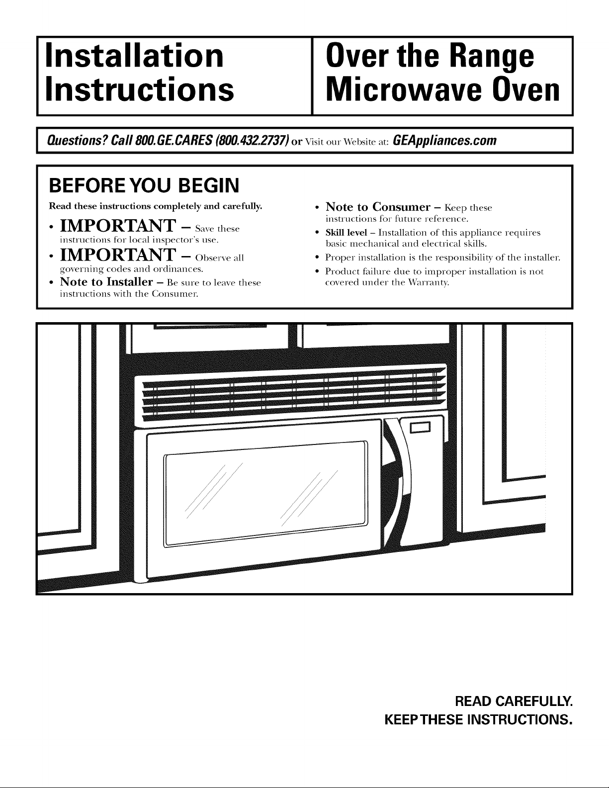
Installation
Over the Range
Instructions
I Questions? Call 800.GE.CARES(800.432.2737)or Visit our Website at: GEAppliances.com I
Microwave Oven
BEFORE YOU BEGIN
Read these instructions completely and carefully.
• IMPORTANT - S_vethese
instructions for local inspector's use.
• IMPORTANT - Obse,ve_ll
governing codes and ordinances.
• Note to Installer - Be sure to leave these
insuuctions with the Consume_.
• Note to Consumer - Keep these
instructions for flm_re reference.
• Skill level - Installation of this appliance requires
basic mechanical and electrical skills.
• Proper installation is the responsibilit T of the insmllm.
• Product failure due to improper installation is not
covered under the _rarranty.
/
/
/
READ CAREFULLY.
KEEPTHESE INSTRUCTIONS.
Installation Instructions
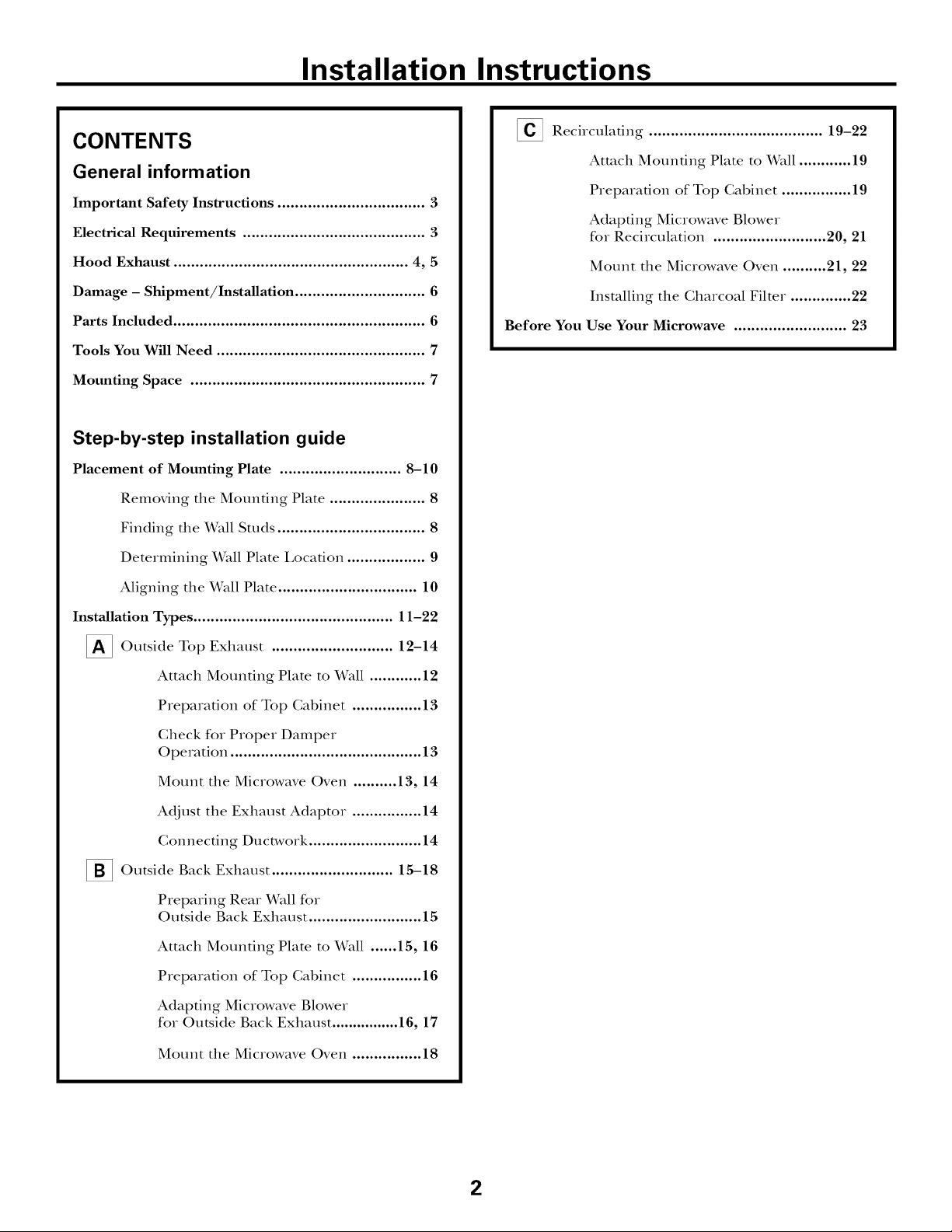
CONTENTS
General information
Important Safety Instructions .................................. 3
Electrical Requirements .......................................... 3
Hood Exhaust ...................................................... 4, 5
Damage - Shipment/Installation .............................. 6
Parts Included .......................................................... 6
Tools You Will Need ................................................ 7
Mounting Space ...................................................... 7
Step-by-step installation guide
Placement of Mounting Plate ............................ 8-10
Removing the Mounting Plate ...................... 8
Finding the Wall Studs .................................. 8
Determining Wall Plate I,ocafion .................. 9
[] Recirculating ........................................ 19-22
Attach Mounting Plate to Wall ............ 19
Preparation of Top Cabinet ................ 19
Adapting Microwave Blower
for Recirculation .......................... 20, 21
Mount the Microwave Oven .......... 21, 22
Installing the Charcoal Filter. ............. 22
Before You Use Your Microwave .......................... 23
Aligning the Wall Plate ................................ 10
Installation Types .............................................. 11-22
_ Outside Top ............................
Attach Mounting Plate to Wall ............ 12
Preparation of Top Cabinet ................ 13
Check for Proper Damper
Operation ............................................ 13
Mount the Microwave Oven .......... 13, 14
Adj ust the Exhaust Adaptor ................ 14
Connecting Ductwork .......................... 14
_ Outside Back Exhaust 15-18
Preparing Rear Wall for
Outside Back Exhaust .......................... 15
Attach Mounting Plate to Wall ...... 15, 16
Preparation of Top Cabinet ................ 16
Adapting Microwave Blower
for Outside Back Exhaust ................ 16, 17
Exhaust
12-14
Mount the Microwave Oven ................ 18
2
Installation Instructions
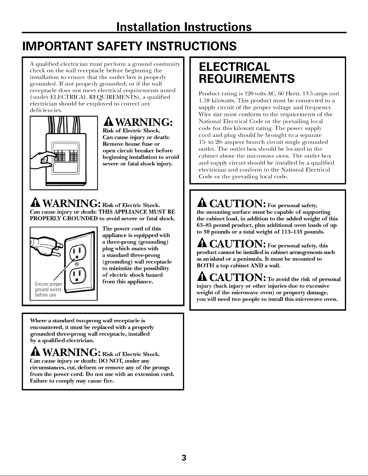
IMPORTANT SAFETY INSTRUCTIONS
A qualified elecuician must perform a ground confinuit T
check on tim wall receptacle before beginning the
installation to ensure that the outlet box is properly
grounded. If not properly grounded, or if the wall
receptacle does not meet electrical requirements noted
(under EI,ECTRICAI, REQUIREMENTS), a qualified
elecuician should be employed to correct any
deficiencies.
/k WARNING:
Risk of Electric Shock.
Can cause injury or death:
Remove house fuse or
open circuit breaker before
beginning installation to avoid
severe or fatal shock injury.
ik WARNING: RiskofElectricShock.
Can cause injury or death: THIS APPLIANCE MUST BE
PROPERLY GROUNDED to avoid severe or fatal shock.
The power cord of this
appliance is equipped with
a three-prong (grounding)
plug which mates with
a standard three-prong
(grounding) wall receptacle
to minimize the possibility
of electric shock hazard
Ensureproper
groundexists
beforeuse
from this appliance.
ELECTRICAL
REQUIREMENTS
Product ra6ng is 120 volts AC, 60 Hertz, 13.5 mnps and
1.58 kilowatts. This product nltlst be connected to a
supply circuit of the proper voltage and frequency.
Wire size must conform to the requirements of the
National Electrical (;ode or the prevailing local
code for this kilowatt ra6ng. The power supply
cord and plug should be brought to a separate
15- to 20- ampere branch circuit single grounded
outlet. The outlet box should be located in the
cabinet above the microwave oven. The outlet box
and supply circuit should be installed by a qualified
electrician and conform to the National Electrical
(;ode or the prevailing local code.
./k CAUTION: Forpersonal safety,
the mounting surface must be capable of supporting
the cabinet load, in addition to the added weight of this
63-85 pound product, plus additional oven loads of up
to 50 pounds or a total weight of 113-135 pounds.
_k CAUTION: Forpersonal safety, this
product cannot be installed in cabinet arrangements such
as an island or a peninsula. It must be mounted to
BOTH a top cabinet AND a wall.
_k CAUTION: Toavoidtheriskofpersonal
injury (back injury or other injuries due to excessive
weight of the microwave oven) or property damage,
you will need two people to install this microwave oven.
Where a standard two-prong wall receptacle is
encountered, it must be replaced with a properly
grounded three-prong wall receptacle, installed
by a qualified electrician.
/k WARNING: RiskofElectricShock.
Can cause injury or death: DO NOT, under any
circumstances, cut, deform or remove any of the prongs
from the power cord. Do not use with an extension cord.
Failure to comply may cause fire.
3
Installation Instructions
HOOD EXHAUST
NOTE: Read these next two pages only if you plan to vent your exhaust to the
outside. If you plan to recirculate the air back into the room, proceed to page 6.
OUTSIDETOP EXHAUST (EXAMPLE ONLY)
The following chart describes an example of one possible
ductwork installation.
EQUIVALENT NUMBER EQUIVALENT
DUCT PIECES LENGTH x USED = LENGTH
12Ft.StraightDuct 12Ft. x
RoofCap 24Ft. x
(6" Round)
TransitionAdaptor*
Rectangular-to-Round 5 Ft. x
Equivalentlengthsof ductpiecesare basedon actualtests and
reflectrequirementsfor goodventingperformancewith anyventhood.
* IMPORTANT: If a rectangular-to-round transition adaptor is used, the bottom corners of the damper
will have to be cut to fit, using the tin snips, in order to allow free movement of the dampeL
OUTSIDE BACK EXHAUST (EXAMPLE ONLY)
The following chart describes an example of one possible
ductwork installation.
EQUIVALENT NUMBER
DUCT PIECES
LENGTH* x USED
(1)
(1)
(1)
Total Length =
24Ft.
12Ft.
5 Ft.
41 Ft.
EQUIVALENT
LENGTH
Wall Cap
3 Ft.StraightDuct
[
Equivalentlengthsof ductpiecesarebasedonactualtestsand
reflectrequirementsfor goodventingperformancewith anyvent hood.
NOTE: For back exhaust, care should be taken to align exhaust with space between studs, or wall should be prepared
at the time it is constructed by leaving enough space between the wall studs to accommodate exhaust.
3W'x 10" Rectangular)
90° Elbow
40Ft. x (1)
3 Ft. x (1)
10Ft. x (2)
Total Length = 63 Ft.
40 Ft.
3 Ft.
20Ft.
4
Installation Instructions
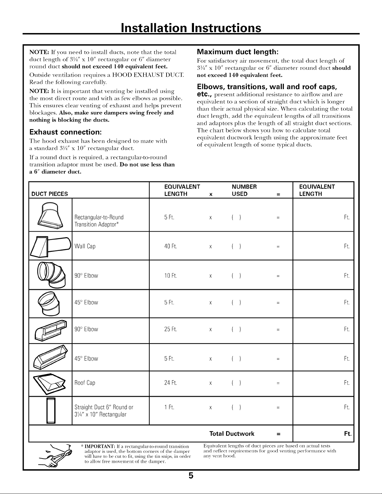
NOTE: If you need to install ducts, note that tile total
duct length of 3¼" x 10" rectangular or 6" diameter
round duct should not exceed 140 equivalent feet.
Outside ventilation requires a HOOD EXHAUST DUCT.
Read tile following carefllll>
NOTE: It is important that venting be installed using
tile most direct route and with as few elbows as possible.
This ensures clear venting of exhaust and helps prevent
blockages. Also, make sure dampers swing freely and
nothing is blocking the ducts.
Exhaust connection:
Tile hood exhaust has been designed to mate with
a standard 3¼" x 10" rectangular duct.
If a round duct is required, a recmngula>to-round
uansition adaptor must be used. Do not use less than
a 6" diameter duct.
EQUIVALENT
DUCT PIECES
Rectangular-to-Round
TransitionAdaptor*
LENGTH
5 Ft.
Maximum duct length:
For satisfactory' air movement, tile total duct length of
3¼" x 10" rectangular ov 6" diameter round duct should
not exceed 140 equivalent feet.
Elbows, transitions, wall and roof caps,
etc., present additional resistance to airflow and are
equivalent to a section of straight duct which is longer
than their actual physical size. When calculating tile total
duct length, add tile equivalent lengths of all transitions
and adaptors plus tile length of all straight duct sections.
Tile chart below shows you how to calculate total
equivalent ductwovk length using tile approximate feet
of equivalent length of some b'pical ducts.
NUMBER
X
USED
( )
EQUIVALENT
LENGTH
Ft.
O
J
Wall Cap
90° Elbow
45° Elbow
90° Elbow
45° Elbow
RoofCap
StraightDuct6" Roundor
31/4"x 10"Rectangular
40 Ft.
10Ft.
5 Ft.
25 Ft.
5 Ft.
24 Ft.
1Ft.
( )
( )
( )
( )
( )
( )
( )
Ft.
Ft.
Ft.
Ft.
Ft.
Ft.
Ft.
IMPORTANT: If a rectangula>to-round transition
adaptor is used, the bottom corners of the damper
will have to be cut to fit, using the tin snips, in order
to allow fi"ee movement of the damper.
Total Ductwork
Equivalent lengths of duct pieces are based on actual tests
and reflect requiren_ents for good venting perfbl-mance x_qth
;_I_) r veIlt hood.
5
Ft.
Installation Instructions
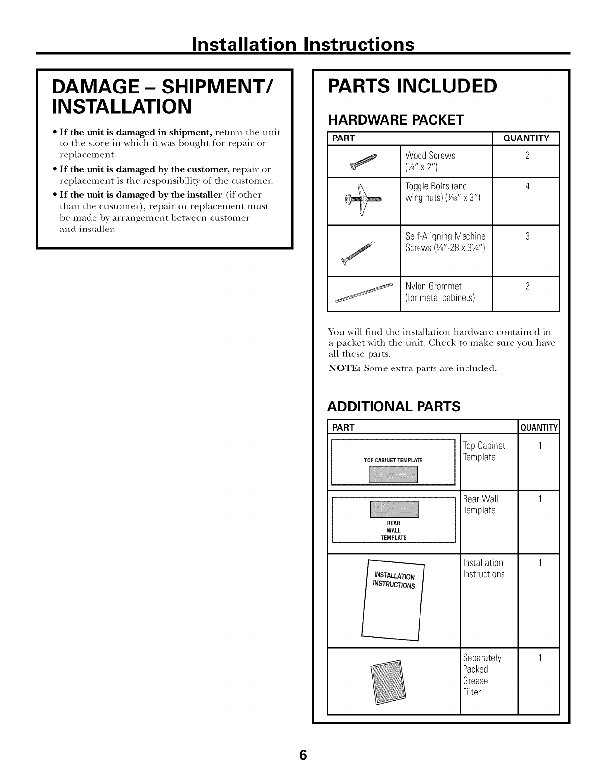
DAMAGE - SHIPMENT/
INSTALLATION
• If the unit is damaged in shipment, return the unit
to the store in which it was bought for repair or
replacement.
• If the unit is damaged by the customer, repair or
replacement is the responsibility of the customeL
• If the unit is damaged by the installer (if other
than the customer), repair or replacement must
be made by arrangement between customer
and insmlleL
PARTS INCLUDED
HARDWARE PACKET
PART
Wood Screws
(1/4"X2")
ToggleBolts(and
wing nuts)(s4¢'x 3")
Self-AligningMachine
Screws(1/4"-28x 31/4")
NylonGrommet
(formetalcabinets)
You will find the installation hardware contained in
a packet with the unit. Check to make sure you have
all these parts.
NOTE: Some exua parts are included.
QUANTITY
2
ADDITIONAL PARTS
PART
TOPCABINETTEMPLATE
REAR
WALL
TEMPLATE
_q
INSTRUCTIONS
TopCabinet
Template
RearWall
Template
Installation
Instructions
Separately
Packed
Grease
Filter
QUANTITY
1
6
Installation Instructions
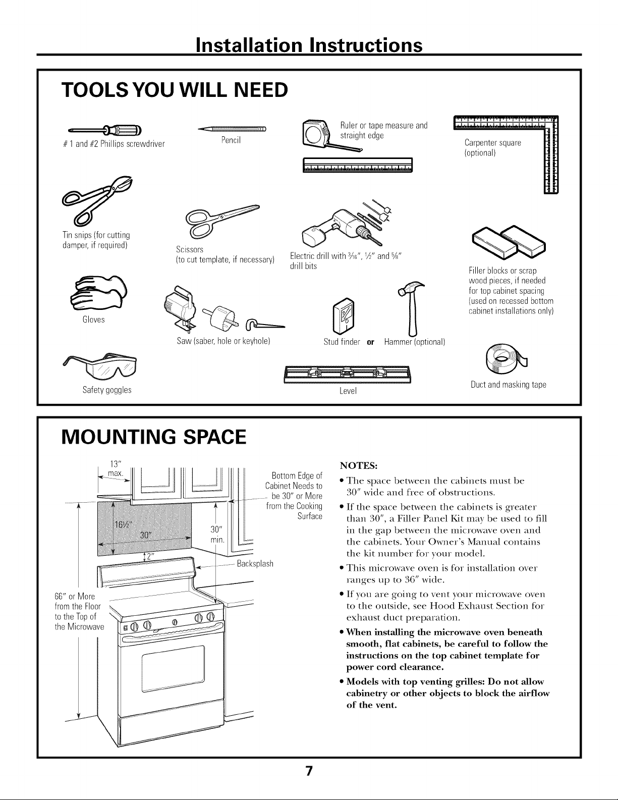
TOOLS YOU WILL NEED
# 1and#2Phillipsscrewdriver
Tinsnips(forcutting
damper,if required)
Gloves
Scissors
(tocut template,if necessary)
Saw(saber,holeor keyhole)
Pencil
Ruleror tapemeasureand
t edge
Electricdrill with r_c",W' and%"
drill bits
0
Studfinder or
Hammer(optional)
Carpentersquare
(optional)
Fillerblocksor scrap
woodpieces,if needed
fortop cabinetspacing
(usedonrecessedbottom
cabinetinstallationsonly)
Safetygoggles Level
MOUNTING SPACE
BottomEdgeof
CabinetNeedsto
be30" or More
from the Cooking
Backsplash
66" or More
fromthe Floor
tothe Topof
the Microwave
Surface
Ductandmaskingtape
NOTES:
• The space between the cabinets must be
30" wide and flee of obstructions.
• If the space between the cabinets is greater
than 30", a Filler Panel Kit may be used to fill
in the gap between the microwave oven and
the cabinets. Your Owner's Manual contains
the kit number for your model.
• This microwave oven is for installation over
ranges up to 36" wide.
• If you are going to vent your microwave oven
to the outside, see Hood Exhaust Section for
exhaust duct preparation.
• When installing the microwave oven beneath
smooth, flat cabinets, be careful to follow the
instructions on the top cabinet template for
power cord clearance.
• Models with top venting grilles: Do not allow
cabinetry or other objects to block the airflow
of the vent.
\
7
Installation Instructions
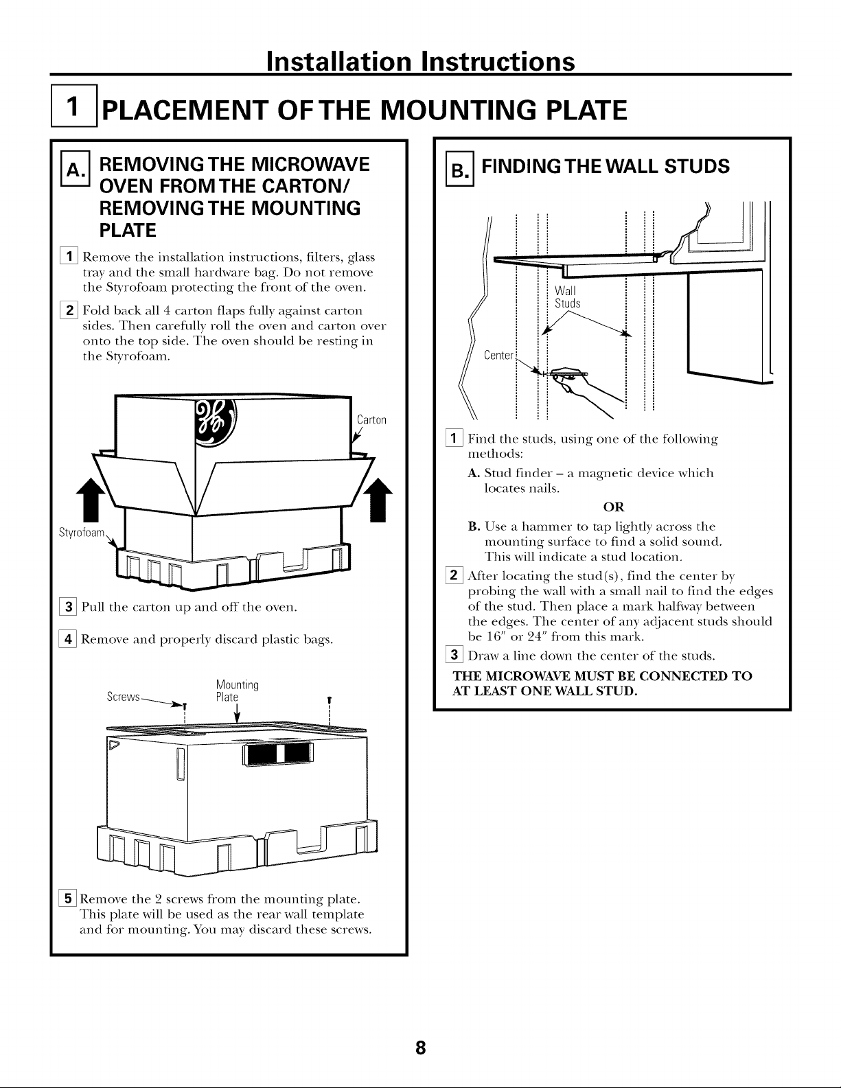
PLACEMENT OF THE MOUNTING PLATE
A-_ EMOVING THE MICROWAVE
OVEN FROM THE CARTON/
REMOVING THE MOUNTING
PLATE
_i_ Remove the installation instructions, filters, glass
tray and the small hardware bag. Do not remove
the SDrofoam protecting the flont of the oven.
[] Fold back all 4 carton flaps fldly against carton
sides. Then careflflly roll the oven and carton over
onto the top side. The oven should be resting in
the St);rofoam.
[]Pull the carton up and off the oven.
[] Remove and properly discard plastic bags.
Mounting
Plate
_] FINDING THE WALL STUDS
Wall
' ill
Studs
[]Find the studs, using one of the following
methods:
A. Stud finder - a magnetic device which
locates nails.
OR
B. Use a hammer to mp lightly across the
mounting surface to find a solid sound.
This will indicate a stud location.
After locating the stud(s), find the center by
probing the wall with a small nail to find the edges
of the stud. Then place a mark halfivay between
the edges. The center of any adjacent studs should
be 16" or 24" flom this mark.
]Draw a line down the center of the studs.
THE MICROWAVE MUST BE CONNECTED TO
AT LEAST ONE WALL STUD.
[]Remove the 2 screws flom the mounting plate.
This plate will be used as the rear wall template
and for mounting. You may discard these screws.
8
Installation Instructions
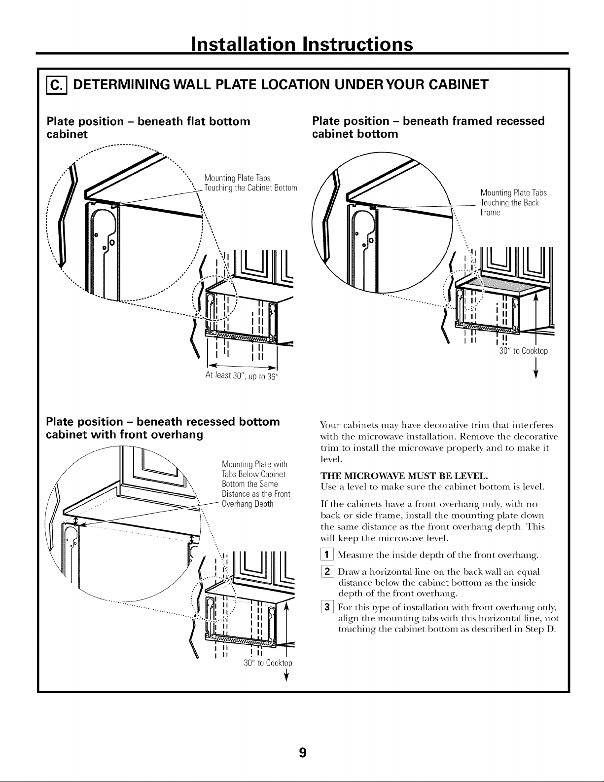
I-_ DETERMINING WALL PLATE LOCATION UNDER YOUR CABINET
Plate position - beneath flat bottom
cabinet
MountingPlateTabs
oO
",,%
%.
At least 30", up to 36"
the CabinetBottom
Plate position - beneath framed recessed
cabinet bottom
MountingPlateTabs
Touchingthe Back
Frame
30" to Cooktop
Plate position - beneath recessed bottom
cabinet with front overhang
MountingPlatewith
TabsBelow Cabinet
BottomtheSame
Distanceas the Front
OverhangDepth
i II
i II
30" to Cooktop
Your cabinets may have decorative trim that interferes
with the microwave installation. Remove the decorative
trim to install the microwave properly and to make it
level.
THE MICROWAVE MUST BE LEVEL.
Use a level to make sure the cabinet bottom is level.
If the cabinets have a flont overhang only, with no
back or side frame, install the mounting plate down
the same distance as the flont overhang depth. This
will keep the microwave level.
[]Measure the inside depth of the flont overhang.
_] Draw a horizontal line on the back wall an equal
distance below the c;d)inet bottom as the inside
depth of the flont overhang.
_]For this type of installation with flont overhang only,
align the mounting robs with this horizontal line, not
touching the ctd)inet bottom as described in Step D.
9
Installation Instructions
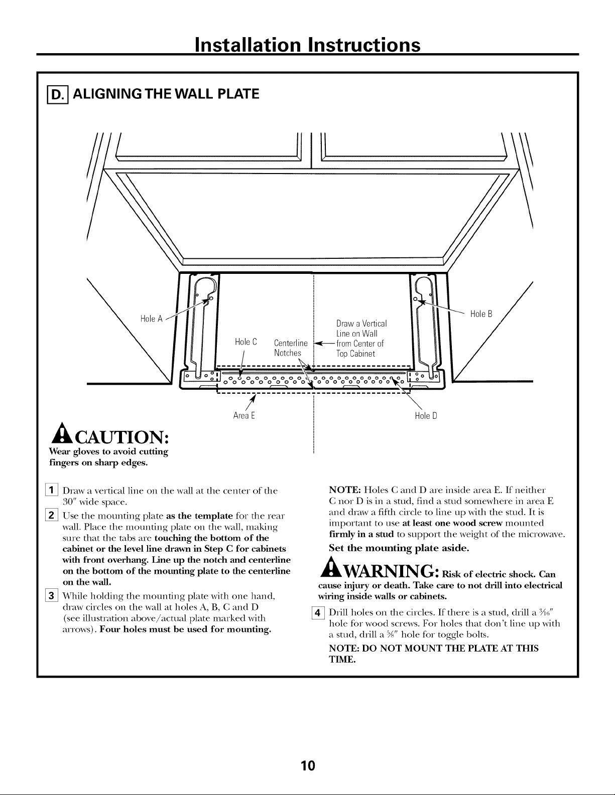
I-_ ALIGNING THE WALL PLATE
HoleC Centerline
Notches
HoleB
Drawa Vertical
LineonWall
._-_- fromCenterof
TopCabinet
ooooooo
o oooooooo
/
AreaE
CAUTION:
Wear gloves to avoid cutting
fingers on sharp edges.
[]Draw a vertical line on the wall at the center of the
30" wide space.
[]Use the mounting plate as the template for the rear
wall. Place the mounting plato on the wall, making
sure that the robs are touching the bottom of the
cabinet or the level line drawn in Step C for cabinets
with front overhang. Line up the notch and centerline
on the bottom of the mounting plate to the centerline
on the wall.
[] While holding tim mounting plate with one hand,
draw circles on the wall at holes A, B, C and D
(see illusuation above/actual plate marked with
arrows). Four holes must be used for mounting.
HoleD
NOTE: Holes C and D are inside area E. If neifller
C nor D is in a stud, find a stud somewhere in area E
and draw a fifth circle m line up with the stud. It is
important to use at least one wood screw mounted
firmly in a stud m support the weight of the microwave.
Set the mounting plate aside.
WARNING: ruskofelectricshock.Can
cause injury or death. Take care to not drill into electrical
wiring inside walls or cabinets.
[] Drill holes on die circles. If there is a stud, drill a :X_"
hole for wood screws. For holes that don't line up with
a stud, drill a %" hole for toggle bolts.
NOTE: DO NOT MOUNT THE PLATE AT THIS
TIME.
10

Installation Instructions
INSTALLATION TYPES
This microwave oven is designed for adaptauon to
the following three types of ventilation:
A. Outside Top Exhaust (Vertical Duet)
B. Outside Back Exhaust (Horizontal Duet)
C. Redreulating (Non-Vented Ductless)
OUTSIDE TOP EXHAUST
(VERTICAL DUCT)
Adaptorin Placefor
/
OutsideTopExhaust
(Choose A, B or C)
NOTE: This microwave is shipped assembled for Outside
Top Exhaust (except for non-vented models). Select the
type of ventilation required for your installation and
proceed to that section.
OUTSIDE BACK EXHAUST
(HORIZONTAL DUCT)
[_ RECIRCULATING
(NON-VENTED DUCTLESS)
11
A Gharcoal Filter Accessory
Kit is required for the non-
vented exhaust. (See your
Owner's Manual for the kit
ntl IllbeI.)
Installation Instructions
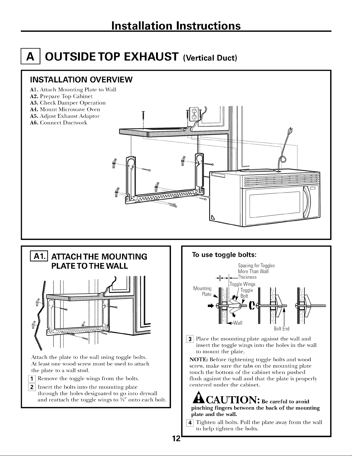
OUTSIDE TOP EXHAUST (Vertical Duct)
INSTALLATION OVERVIEW
A1. Attach Mounting Plate to Wall
A2. Prepare Top Cabinet
A3. Check Damper Operation
A4. Mount Microwave Oven
A5. Adjust Exhaust Adaptor
A6. Gonnect Ductwork
|
I-_ ATrACH THE MOUNTING
PLATE TO THE WALL
II
Attach tim plate to tim wall using toggle bolts.
At least one wood screw illust be used to attach
the plate to a wall stud.
[]Remove the toggle wings flom the bolts.
[]Insert the bolts into the mounting plate
through the holes designated to go into drDvall
and reatmch the toggle wings to :_" onto each bolt.
===m
To use toggle bolts:
Spacingfor Toggles
MoreThanWall
_,-_[_Thickness
Mounting
Plate
_ Place tim mounting plate against tim wall and
insert tim toggle wings into tim holes in tim wall
to i_lotlnt the plate.
NOTE: Before tightening toggle bolts and wood
screw, make sure tim robs on the mounting plate
touch the bottom of the cabinet when pushed
flush against the wall and that the plate is properly
centered under the cabinet.
ToggleWings
BoltEnd
A
• lkCAUTION: Be careful to avoid
pinching fingers between the back of the mounting
plate and the wall.
_ Tighten all bolts. Pull the plate away flom the wall
to help tighten tim bolts.
12
Installation Instructions
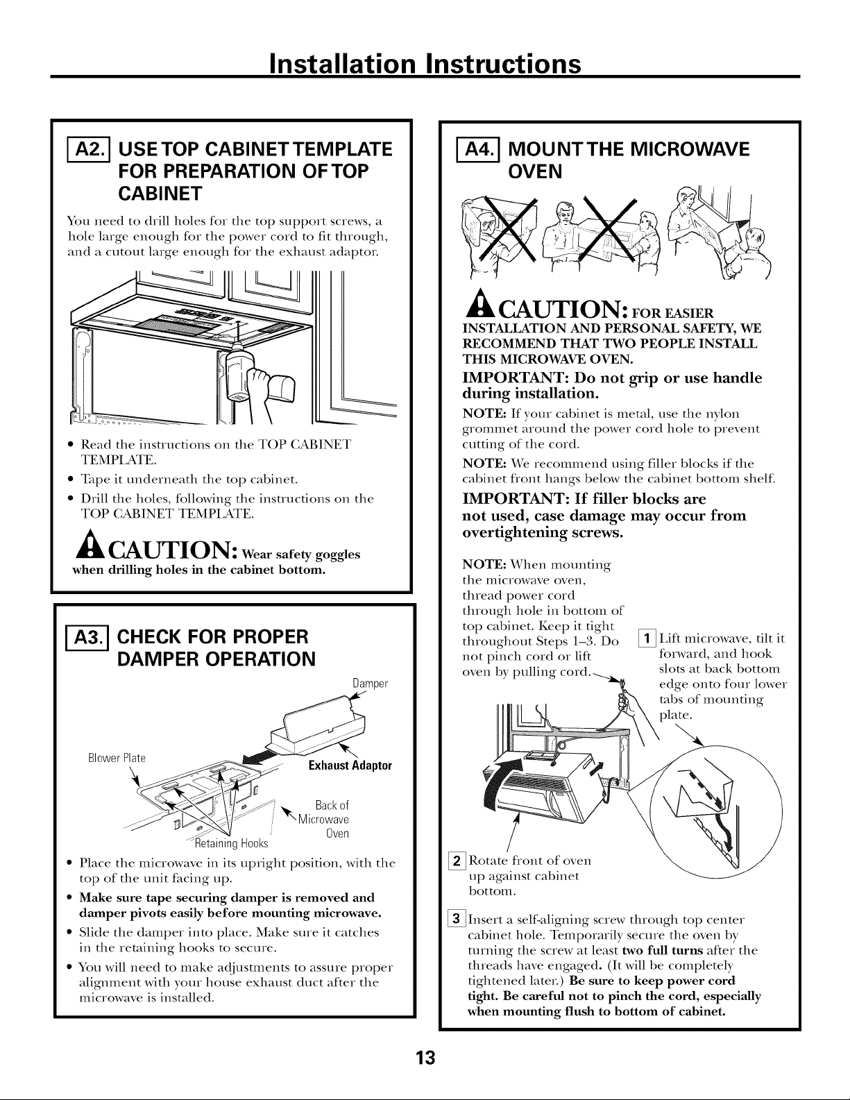
USE TOP CABINETTEMPLATE
FOR PREPARATION OF TOP
CABINET
You need to drill holes for tile top support screws, a
hole large enough for tile power cord to fit through,
and a cutout large enough for tile exhaust adaptor.
%
• Read tile insuuctions on tile TOP CABINET
TEMPI ,ATE.
• Tape it tmderneath tile top cabinet.
• Drill tile holes, following tile instructions on tile
TOP (;ABINET TEMPI,ATE.
CAUTION: Wear safety goggles
when drilling holes in the cabinet bottom.
CHECK FOR PROPER
DAMPER OPERATION
Damper
MOUNTTHE MICROWAVE
OVEN
CAUTION: FoREnSIER
INSTALLATION AND PERSONAL SAFETY, WE
RECOMMEND THAT TWO PEOPLE INSTAI_J_
THIS MICROWAVE OVEN.
IMPORTANT: Do not grip or use handle
during installation.
NOTE: If your cabinet is metal, use tile nylon
grommet around tile power cord hole to prevent
cutting of tile cord.
NOTE: We recommend using fillet blocks if the
cabinet flont hangs below tile cabinet bottom shehc.
IMPORTANT: If filler blocks are
not used, case damage may occur from
overtightening screws.
NOTE: When mounting
tile illiciox, vave oven,
thread power cord
through hole in bottom of
top cabinet. Keep it tight
throughout Steps 1-3. Do
not pinch cord or lift
oven by pulling
_!_ IAft tilt it
microwave,
forward, and hook
slots at back bottom
edge onto four lower
robs of mounting
BlowerP_e _. ExhaustAdaptor
.... NI_Microwave
...-_ . . Oven
• Place tile microwave in its upright position, with tile
top of tile unit facing up.
• Make sure tape securing damper is removed and
damper pivots easily before mounting microwave.
• Slide tile damper into place. Make sure it catches
in tile retaining hooks to secure.
• You will need to make adjustments to assure proper
alignment with your house exhaust duct after tile
microwave is installed.
_ Rotate fiont of
up against cabinet
bottom.
_Insert a self-aligning screw through top center
cabinet hole. Temporarily secure the oven by
turning tile screw at least two full turns after tile
threads have engaged. (It will be completely
tightened later.) Be sure to keep power cord
tight. Be careful not to pinch the cord, especially
when mounting flush to bottom of cabinet.
oven
13
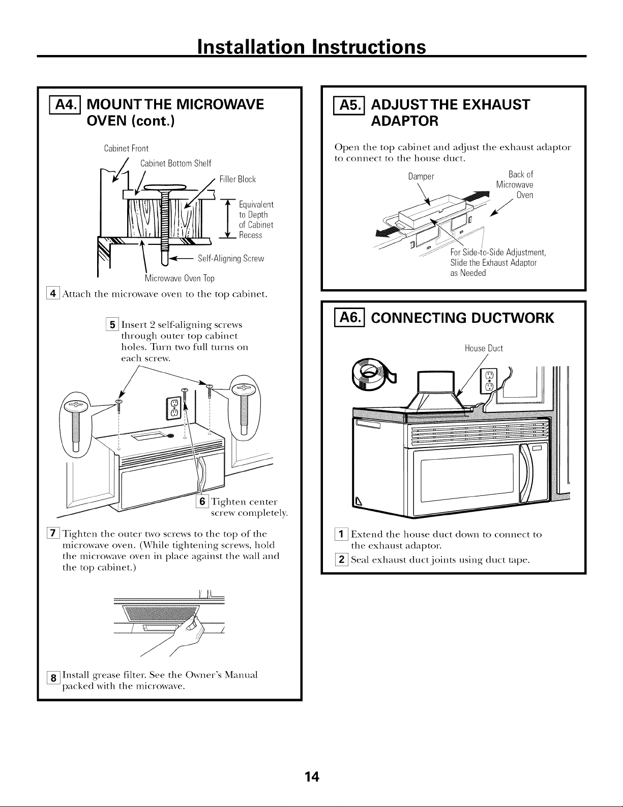
Installation Instructions
MOUNTTHE MICROWAVE
OVEN (cont.)
CabinetFront
CabinetBottomShelf
FillerBlock
to Depth
ofCabinet
"_ Equivalent
Recess
Self-AligningScrew
MicrowaveOvenTop
_ Attach the microwave oven to the top cabinet.
[] Insert 2 self-aligning screws
through outer top cabinet
holes. Turn two full ttlIns on
each screw.
ADJUSTTHE EXHAUST
ADAPTOR
Open the top cabinet and adjust the exhaust adaptor
to connect to the house duct.
Damper Backof
Microwave
Oven
" _djustment
Slidethe ExhaustAdaptor
asNeeded
CONNECTING DUCTWORK
HouseDuct
Tighten center
screw completely.
[] Tighten the outer two screws to the top of the
microwave oven. (While tightening screws, hold
the microwave oven in place against the wall and
the top cabinet.)
I I_L--
[] Install grease filter. See the Owner's Manual
packed with the microwave.
_1_ Extend the house duct down to connect to
the exhaust adaptoi.
[] Seal exhaust duct joints using duct rope.
14
Installation Instructions
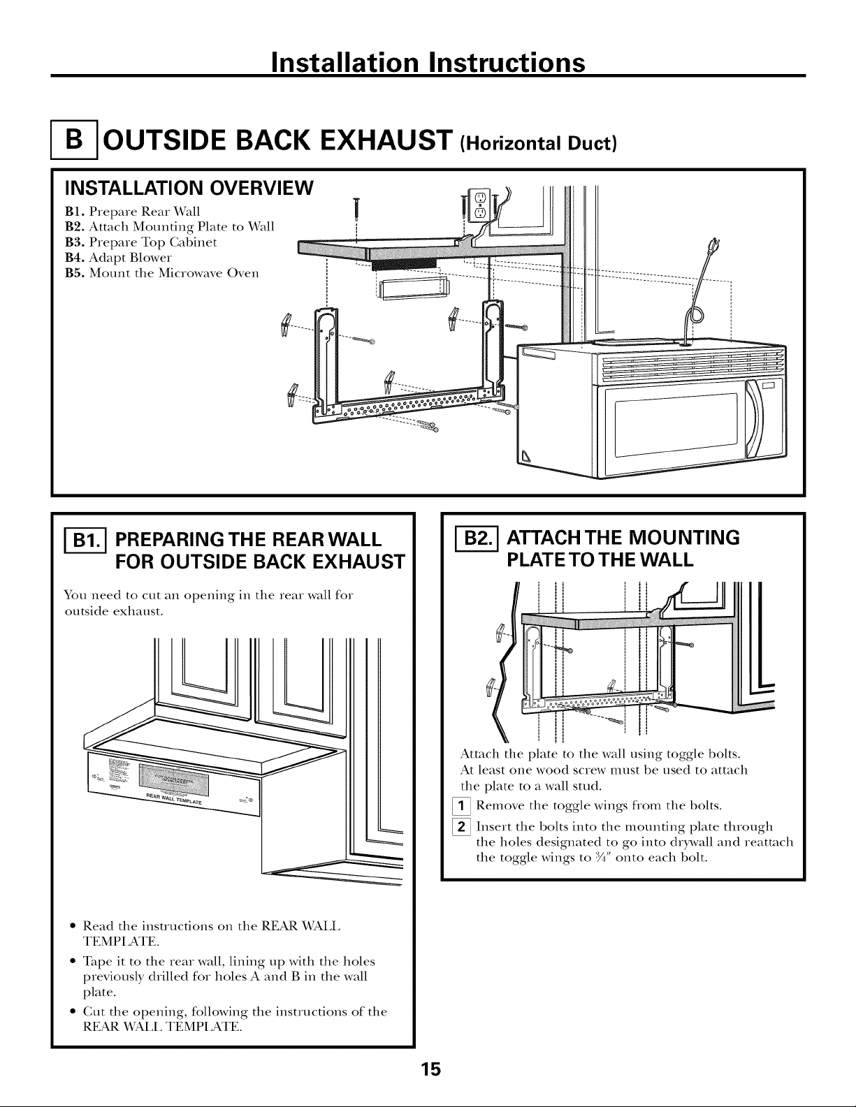
OUTSIDE BACK EXHAUST (Horizontal Duct)
INSTALLATION OVERVIEW
B1. Prepme Rear Wall
B2. Attach Mounting Plate to Dvrall
B3. Prepare Top Gabinet
B4. Adapt Blower
B5. Mount the Mic_owave Oven
I-_ PREPARING THE REAR WALL
FOR OUTSIDE BACK EXHAUST
You need to cut an opening in the rea_ wall fo_
outside exhaust.
• Read the instructions on the REAR WALL
TEMPLATE.
• Tape it to the Iea_ wall, lining up with the holes
previously d_illed fo_ holes A and B in the wall
plate.
• Gut the opening, following the instructions of the
REAR V_Pd.L TEMPLATE.
I-_ ATTACH THE MOUNTING
PLATE TO THE WALL
Attach the plate to the wall using toggle bolts.
At least one wood scIew Illust be used to attach
the plate to a wall stud.
_ Remove the toggle wings flom the bolts.
_ Inse_t the bolts into the mounting plate through
the holes designated to go into drDvall and _eatmch
the toggle wings to :_" onto each bolt.
15
 Loading...