


GE JB258DM1BB, JB258DM1CC, JB258DM1WW, JB258RM1SS, JB625DK5BB Installation Guide
...
Installation Instructions
Free-Standing and Front
Control Electric Ranges
BEFORE YOU BEGIN
Read these instructions completely and carefully.
• IMPORTANT — Save these
instructions for local inspector’s use.
• IMPORTANT — Observe all governing codes and ordinances.
•Note to Installer – Be sure to leave these instructions with Consumer.
•Note to Consumer – Keep these instructions for future reference.
•Skill level – Installation of this appliance requires basic mechanical skills and advanced electrical skills.
•Proper installation is the responsibility of the installer.
•Product failure due to improper installation is not covered under Warranty.
FOR YOUR SAFETY:
 WARNING
Tip-Over Hazard
• A child or adult can tip the range and be killed.
• Install the anti-tip bracket to the wall or floor.
• Engage the range to the anti-tip bracket by sliding the range back such that the foot is engaged.
•Re-engage the anti-tip bracket if the range is moved.
•Failure to do so can result in death or serious burns to children or adults.
If you did not receive an anti-tip bracket with your purchase, call 1.800.626.8774 to receive one at no cost. (In Canada, call 1.800.561.3344.) For installation instructions of the bracket,
visit: www.GEAppliances.com.
(In Canada, www.GEAppliances.ca.)
Anti-Tip Bracket
Kit Included

 WARNING Before beginning the installation, switch power off at service panel and lock the service disconnecting means to prevent power from being switched on accidentally.
When the service disconnecting means cannot be locked, securely fasten a prominent warning device, such as a tag, to the service panel.
MATERIALS YOU MAY NEED |
TOOLS YOU WILL NEED |
||
|
|
Drill with 1/8” Bit |
Tape Measure |
|
|
Safety Glasses |
Pliers |
Squeeze Connector |
(UL Listed 40 AMP) |
Adjustable Wrench |
1/4” Nut Driver |
Level |
|
||
(For Conduit 4-Wire Cord 4’ long OR |
|
||
Installations Only) |
3-Wire Cord 4’ long |
Tin Snips |
|
1 REMOVE PACKAGING MATERIALS: Failure to remove packaging
materials could result in damage to the appliance. Remove all packing parts from oven, racks, heating elements and drawer. Also, remove protective film and labels on the outer door, cooktop and control panel.
2 PREPARE THE OPENING (FOR INDOOR USE ONLY)
See illustrations for all rough-in and spacing dimensions. The range may be placed with 0” clearance (flush) at the back wall and side walls of the cabinet.
|
21»2” (31»4” on |
|
|
|
|
|
double ovens) |
30” |
|
|
|
|
|
|
|
|
|
|
|
|
25” |
21»2” (31»4” on |
|
Unit will not mount flush |
(23” on |
double ovens) |
|||
double |
(73»4” on |
|
|||
to counter when heights |
ovens) |
|
|||
|
double |
|
|||
are less than 36”. |
|
|
ovens) |
|
|
|
|
|
|
61»2” |
297»8” |
|
|
|
|
|
|
|
|
|
4” (3” |
|
297»8” |
297»8” |
|
|
on double |
||
|
|
ovens) |
|
||
|
47” |
Acceptable electrical |
365»8” |
||
|
(36” to |
|
|||
|
cooktop |
outlet area. Orient |
|
36” |
|
|
height) |
electrical receptacle |
|
NOTE: |
|
|
NOTE: |
so the length is |
|
Rear wall |
|
|
Rear wall |
parallel to floor. |
|
to front |
|
|
|
of door |
|||
|
to front |
Use a flush mount |
|
glass. 253»4” |
|
|
of door |
|
|||
|
glass.251»2” |
outlet for double |
|
451»8” (477»8” on |
|
(253»4” on |
475»8” |
oven models. |
|
single oven) |
|
double oven) |
(451»8” on |
|
|
FRONT CONTROL |
|
|
double oven) |
|
|
||
REAR CONTROL
NOTE: Use a 4’ power cord to prevent interference with the storage drawer. Power cords 41»2’ to 6’ long may have to be dressed to allow for proper drawer closing.
MINIMUM DIMENSIONS BETWEEN COOKTOP, WALLS AND ABOVE THE COOKTOP:
A.Make sure the wall covering, countertop, flooring and cabinets around the range can withstand the heat (up to 200°F) generated by the range.
B.Allow 30” minimum clearance between surface units and bottom of unprotected wood or metal cabinet, or allow a 24” minimum when bottom of wood or metal cabinet is protected by no less than 1/4” thick flame retardant millboard covered with not less than No 28 MSG sheet metal, (.015”), .015” thick stainless steel, .024” aluminum or .020” copper.
|
B |
|
C |
NOTE C |
Both |
|
Sides |
A |
A |
C.This appliance has been approved for 0” spacing to adjacent surfaces above the cooktop. However, a 6” minimum spacing to surfaces less than 15” above the cooktop and adjacent cabinet is recommended to reduce exposure to steam, grease splatter and heat.
To reduce the risk of burns or fire when reaching over hot surface elements, cabinet storage space above the cooktop should be avoided. If cabinet storage space is to be provided above the cooktop, the risk can be reduced by installing a range hood that projects at least 5” beyond the front of the cabinets. Cabinets installed above the cooktop must be no deeper than 16”.
3 ELECTRICAL REQUIREMENTS

 WARNING This appliance must be properly grounded.

 WARNING All new constructions, mobile homes, recreational vehicles and installations where local codes do not allow grounding through neutral, require a 4-conductor UL-listed range cord.

 WARNING To prevent fire or shock, do not use an extension cord with this appliance.

 WARNING To prevent shock, remove house fuse or open circuit breaker before beginning installation.
We recommend you have the electrical wiring and hookup of your range connected by a qualified electrician. After installation, have the electrician show you how to disconnect power from the range.
You must use a single-phase, 120/208 VAC or 120/240 VAC, 60 hertz electrical system. If you connect to aluminum wiring, properly installed connectors approved for use with aluminum wiring must be used.
Effective January 1, 1996, the National Electrical Code requires that new construction (not existing) utilize a 4-conductor connection to an electric range. When installing an electric range in new construction, mobile home, recreational vehicle, or an area where local codes prohibit grounding through the neutral conductor, refer to the section on four-conductor branch circuit connections.
Check with your local utilities for electrical codes which apply in your area. Failure to wire your oven according to governing codes could result in a hazardous condition. If there are no local codes, your oven must be wired and fused to meet the National Electrical Code, NFPA No. 70 – latest edition, available from the National Fire Protection Association.
This appliance must be supplied with the proper voltage and frequency, and connected to an individual, properly grounded, 40 amp (minimum) branch circuit protected by a circuit breaker or time-delay fuse.
Use only a 3-conductor or a 4-conductor UL-listed range cord. These cords may be provided with ring terminals on wire and a strain relief device.
A range cord rated at 40 amps with 125/250 minimum volt range is required. A 50 amp range
FRUG LV QRW UHFRPPHQGHG EXW LI XVHG LW VKRXOG EH PDUNHG IRU XVH ZLWK QRPLQDO » ´ GLDPHWHU connection openings. Care should be taken to center the cable and strain relief within the knockout hole to keep the edge from damaging the cable.
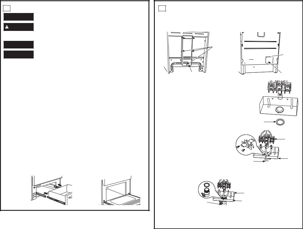
The rating plate is located on the oven frame or on the drawer frame.
SINGLE OVEN |
DOUBLE OVEN |
Rating plate 

Rating plate


4POWER CORD AND CONDUIT INSTALLATION
A.Remove wire cover (on the back of range) by removing screws using a 1/4” nut driver. You can access the terminal block by either removing a terminal block cover (on some models) or the wire cover. Do not discard these screws.
Back of range |
Back of range |

 5 screws to remove
wire cover 
 Screw to
  remove

 terminal block cover
Wire cover
B.For power cord and 1” conduit only, remove the knockout ring (13»8”) located on bracket directly below the terminal block. To remove the knockout, use a pair of pliers to bend the knockout ring away from the bracket and twist until ring is removed.
C.For power cord installations only (see the next step if using conduit), assemble the strain relief in the hole. Insert the power cord through the strain relief and tighten. Allow enough slack to easily attach the cord terminals to the terminal block. If tabs are present at the end of the winged strain relief, they can be removed for better fit.
Terminal block cover
Terminal block  (appearance
 may vary)
Knockout
ring in 
 bracket
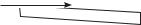


Knockout ring removed
NOTE: Do not install the power cord without |
Strain relief |
a strain relief. The strain relief bracket MUST |
Terminal |
be installed before reinstalling the rear range |
|
wiring cover. |
block |
D. For 3/4” conduit installations only, purchase a |
|
|
|
squeeze connector matching the diameter of |
|
|
|
your conduit and assemble it in the hole. Insert |
|
Bracket |
|
the conduit through the squeeze connector and |
Power cord |
||
|
|||
tighten. Allow enough slack to easily attach the |
|
|
wires to the terminal block. NOTE: Do not install the conduit without a squeeze connector.
The squeeze connector MUST be installed before reinstalling the rear range wire or terminal block cover.
Squeeze |
|
connector |
Terminal block |
|
|
Conduit |
Bracket |
E.Replace wire cover on range back and replace the screws removed earlier. Make sure that no wires are pinched between cover and range back. Replace the terminal block cover if it was removed.
PROCEED TO STEP 5 OR 6.
5 3-WIRE INSTALLATION

 WARNING The neutral or ground wire of the power cord must be connected to the neutral terminal located in the center of the terminal block and the ground strap must connect the neutral terminal to the ground plate. The power leads must be connected to the lower left and the lower right terminals of the terminal block.
DO NOT remove the ground strap connection.
FOR POWER CORD INSTALLATION
A.Remove the 3 lower terminal screws from the terminal block.
B.Insert the 3 terminal screws through each power cord terminal ring and into the lower terminals of the terminal block. Be certain that the center wire (white/neutral) is connected to the center lower position of the terminal block.
C.Tighten screws securely into the terminal block.
FOR CONDUIT INSTALLATION
A.Loosen the 3 lower terminal screws on the terminal block. Strip wire to expose tip about 5/8” long.
B.Insert the center (white/neutral) wire tip through the bottom center terminal block opening. On certain models, the wire will need to be inserted through the ground strap opening and then into the bottom center block opening. Insert the two side bare wire tips into the lower left and the lower right terminal block openings.
C.Tighten the screws until the wire is firmly secured (35 to 50 inch-lbs.). Do not over-tighten the screws.
NOTE: ALUMINUM WIRING: Aluminum building wire may be used but it must be rated for the correct amperage and voltage.
Power Cord |
Conduit |
Terminal block |
Terminal |
(appearance |
block |
may vary) |
|
Neutral terminal |
Wire tips |
|
|
Ground strap |
|
Ground |
|
plate |
|
|
Conduit |
Power cord |
|
PROCEED TO STEP 7. |
|
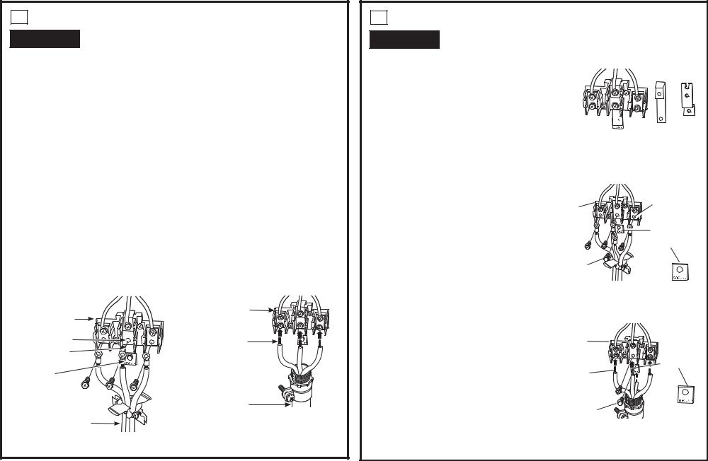
6 4-WIRE INSTALLATION

 WARNING The neutral wire of the supply circuit must be connected to the neutral terminal located in the lower center of the terminal block. The power leads must be
connected to the lower left and the lower right terminals of the terminal block. The grounding lead must be connected to the frame of the range with the ground plate and the green ground screw.
FOR POWER CORD INSTALLATION
A.Remove the 3 lower terminal screws from the terminal block. Remove the ground screw and ground plate and retain them. Cut and discard the ground strap.
DO NOT DISCARD ANY SCREWS.
Before–Power Cord and Conduit
Ground strap
Terminal
block
or
Ground 
 strap Neutral
terminal
After–Power Cord
B. Insert the one ground screw into the power cord |
|
Neutral |
|
ground wire terminal ring, through the ground |
|
||
Terminal |
terminal |
||
plate and into the frame of the range. |
|||
block |
Ground plate |
||
C. Insert the 3 terminal screws (removed earlier) |
|||
|
|||
|
(grounding to |
||
through each power cord terminal ring and into |
|
||
|
range) |
||
the lower terminals of the terminal block. Be |
|
||
|
|
||
certain that the center wire (white/neutral) is |
|
|
|
connected to the center lower position of the |
Ground |
|
|
terminal block. Tighten screws securely into the |
screw |
|
|
terminal block. |
|
|
|
FOR CONDUIT INSTALLATION |
|
|
|
A. Loosen the 3 lower terminal screws on the |
After–Conduit |
|
|
terminal block. Strip wire to exposed tip about |
|
||
|
|
||
5/8” long. |
|
Ground |
|
B. Insert the center (white/neutral) wire tip through |
Terminal |
||
plate |
|||
the bottom center terminal block opening. On |
block |
||
(grounding |
|||
certain models, the wire will need to be ins |
|
||
|
to range) |
||
erted through the ground strap opening and |
Wire |
||
|
|||
then into the bottom center block opening. |
|
||
tips |
|
||
Insert the two side bare wire tips into the lower |
|
||
|
|
||
left and the lower right terminal block openings. |
|
|
|
C. Tighten the screws until the wire is firmly |
Ground screw |
|
|
secured (35 to 50 inch-lbs.). Do not over-tighten |
|
|
|
the screws. |
|
|
NOTE: ALUMINUM WIRING: Aluminum building wire may be used but it must be rated for the correct amperage and voltage.
31-11105-3 09-18 GEA
 Loading...