


GE Home Generator Systems
15,000 and 20,000 Watt
Home Generator Systems
Operator’s Manual
Reproduction |
|
Not |
for |
|
|
Thank you for purchasing this quality-built GE home generator. We’re pleased that you’ve placed your confidence in the GE brand. When operated and maintained according to the instructions in this manual, your home generator will provide many years of dependable service.
This manual contains safety information to make you aware of the hazards and risks associated with home standby generators and how to avoid them. Because we do not necessarily know all the applications this equipment could be used for, it is important that you read and understand these instructions thoroughly before attempting to start or operate this equipment. Save these instructions for future reference.
This home standby generator requires professional installation before use. Refer to the separate installation manual for full information. Your installer should follow the instructions completely.
Where to Find Us
You never have to look far to find GE support and service for your generator. For quick service when you need it, keep your original receipt with this manual. You may contact Customer Service at 888 575 8226 or click on Find a Dealer at BRIGGSandSTRATTON.COM, which provides a list of authorized dealers.
Generator and engine model and serial numbers should be recorded in the installation manual.
Reproduction |
|
Not |
for |
|
|
2
Table of Contents
Important Safety Instructions . . . . . . . . . . . . . . . . 4
Installation . . . . . . . . . . . . . |
. |
. . . |
|
7 |
For the Home Owner . . . . . . . . . . . . |
. |
. . . |
. |
7 |
For the Installing Dealer/Contractor . . . . . |
. |
. . . |
. |
. . . . . . . 7 |
Owner Orientation . . . . . . . . . . . . . |
. |
. . . |
8 |
|
Fuel Factors . . . . . . . . . . . . . . . . |
. |
|
8 |
|
Generator Location . . . . . . . . . . . . |
. |
. . . |
. |
9 |
Delivery Inspection . . . . . . . . . . . . . |
. |
. . . |
10 |
|
Controls . . . . . . . . |
. |
Reproduction |
||||
. . . . |
|
. . . . |
11 |
|||
Setting Exercise Timer . . . . |
. |
. . . . |
|
. . . for. . . . . |
15 |
|
Operation . . . . . . . |
. |
. . . . |
|
. . . . |
. 14 |
|
Automatic Operation . . . . |
. |
. . . . |
. . . . . . |
. . |
14 |
|
Generator Maintenance . . . |
. |
. Not. . . . . . . . |
. . . |
. 18 |
||
Maintenance . . . . . . |
. |
. . . |
|
. . . . . |
. . |
16 |
Fault Detection System . . . |
. |
. . . . |
. . . . . . |
. . |
. 16 |
|
Engine Oil . . . . . . . . . |
. |
. . . . |
. |
. . |
|
18 |
Battery . . . . . . . . . . . |
. |
. . . . |
|
. |
|
19 |
Cleaning the Generator . . . |
. |
. . . . |
. . . . . . |
. . |
. 20 |
|
Storage . . . . . . . . . . |
. |
. . . . |
. |
. |
|
21 |
Troubleshooting . . . . |
. |
. . . . |
|
. . . . |
. . |
. . 22 |
Warranty . . . . . . . . |
. |
. . . |
|
. . . . . |
23 |
|
Product Specifications . . |
. |
. . . |
|
. . . . . |
. . |
. . . . 25 |
3

SAVE THESE INSTRUCTIONS - This manual contains |
|
The manufacturer cannot possibly anticipate every possible |
|||||||||||
important instructions that should be followed during |
|
circumstance that might involve a hazard. The warnings |
|||||||||||
installation and maintenance of the generator and batteries. |
in this manual, and the tags and decals affixed to the unit |
||||||||||||
Safety Symbols and Meanings |
|
|
|
|
|
are, therefore, not all-inclusive. If you use a procedure, work |
|||||||
|
|
|
|
|
|
|
|
|
|
|
method or operating technique that the manufacturer does |
||
|
|
|
|
|
|
|
|
|
|
|
not specifically recommend, you must satisfy yourself that it |
||
|
|
|
|
|
|
|
|
|
|
|
is safe for you and others. You must also make sure that the |
||
|
|
|
|
|
|
|
|
|
|
|
procedure, work method or operating technique that you |
||
Explosion |
Fire |
|
Electrical Shock |
|
choose does not render the generator system unsafe. |
||||||||
|
|
|
|
|
|||||||||
|
|
|
|
|
|
|
|
|
|
|
|
||
|
|
|
|
|
|
|
|
|
|
|
WARNING Running engine gives off carbon monoxide, an |
||
|
|
|
|
|
|
|
|
|
|
|
odo less, colorless, poison gas. |
||
|
|
|
|
|
|
|
|
|
|
|
B eathing carbon mo oxide could cause headache, fatigue, |
||
|
|
|
|
|
|
|
|
|
|
|
|
dizziness, v miti g, co fusion, seizures, nausea, fainting |
|
Toxic Fumes |
Rotating Parts |
|
|
|
Hot Surface |
|
|
or death. |
|||||
|
|
|
|
|
|
|
|
|
|
|
|
• |
Operate generator ONLY outdoors. |
|
|
|
|
|
|
|
|
|
|
|
• Install a ba |
ery operated carbon monoxide alarm near |
|
|
|
|
|
|
|
|
|
|
|
for |
|
|
|
|
|
|
|
|
|
|
|
|
|
|
the bedrooms. |
||
|
|
|
|
|
|
|
|
|
|
|
• Keep exha |
st gas from entering a confined area through |
|
Auto Start |
Explosive Pressure |
|
|
Chemical Burn |
|
win ows, doors, ventilation intakes, or other openings. |
|||||||
|
|
|
|
|
|
||||||||
|
|
|
|
|
|
|
|
|
Not |
|
|||
|
|
|
|
|
|
|
|
|
WARNING The engine exhaust from this product contains |
||||
|
|
|
|
|
|
|
|
|
chemicals known to the State of California to cause cancer, birth |
||||
|
|
|
|
|
|
|
|
|
defects, or other reproductive harm. |
||||
|
|
|
|
|
|
|
|
|
|||||
|
|
|
|
|
|
|
|
|
|
|
|||
Lift Hazard |
Read Manual |
|
|
|
|
||||||||
|
|
|
|
||||||||||
|
|
|
|
|
|
|
|
|
|
|
|
||
|
|
|
|
|
|
|
|
|
|
|
WARNING Certain components in this product and related |
||
The safety alert symbol indicates a potential rsonal |
|
accessories contain chemicals known to the State of California |
|||||||||||
injury hazard. A signal word (DANGER, WA |
NING, or |
|
to cause cancer, birth defects, or other reproductive harm. Wash |
||||||||||
CAUTION) is used with the alert symbol to designate a degree |
hands after handling. |
||||||||||||
|
|
|
|||||||||||
or level of hazard seriousness. A safety symbol may be used |
|
|
|
||||||||||
|
|
|
|
|
|
Reproduction |
|||||||
to represent the type of hazard. The signal word NOTICE is |
|
|
|
||||||||||
used to address practices not related to personal injury. |
|
|
|
|
|||||||||
 DANGER indicates a hazard which, if not avoided, will result in death or serious injury.
 WARNING indicates a hazard which, if not avoided, could result in death or serious injury.
 CAUTION indicates a hazard which, if not avoided, could result in minor or moderate injury.
NOTICE addresses practices not related to personal injury.
4
|
WARNING Storage batteries give off explosive hydrogen gas |
|
|
|
WARNING Generator produces hazardous voltage. |
||
|
during recharging. |
|
|
|
|
Failure to properly ground generator can result in |
|
|
Slightest spark will ignite hydrogen and |
|
|
|
electrocution. |
||
|
cause explosion. |
|
|
|
|
Failure to isolate generator from power utility could result |
|
|
Battery electrolyte fluid contains acid and is |
|
|
in death or injury to electric utility workers due to backfeed |
|||
|
extremely caustic. |
|
|
|
|
of electrical energy. |
|
Contact with battery contents will cause severe chemical burns. |
|
|
• |
When using generator for backup power, notify utility company. |
|||
A battery presents a risk of electrical shock and high short |
|
|
• |
DO NOT touch bare wires or bare receptacles. |
|||
circuit current. |
|
|
|
||||
|
|
|
• |
DO NOT use generator with electrical cords which are worn, |
|||
• |
DO NOT dispose of battery in a fire. Recycle battery. |
|
|
||||
|
|
|
frayed, bare or otherwise damaged. |
||||
• |
DO NOT allow any open flame, spark, heat, or lit cigarette during |
|
|
||||
|
• |
DO NOT handle generator or electrical cords while standing in |
|||||
|
and for several minutes after charging a battery. |
|
|
||||
|
|
|
|
water, while barefoot, or while hands or feet are wet. |
|||
• |
DO NOT open or mutilate the battery. |
|
|
|
|
||
|
|
|
• |
If you must work arou d a u it while it is operating, stand on an |
|||
• |
Wear protective goggles, rubber apron, rubber boots and |
|
|
||||
|
|
|
insulated dry surface to reduce the risk of a shock hazard. |
||||
|
rubber gloves. |
|
|
|
• |
DO NOT allow unqual fied persons or children to operate or |
|
• |
Remove watches, rings, or other metal objects. |
|
|
||||
|
|
|
service genera |
r. |
|||
• |
Use tools having insulated handles. |
|
|
|
• |
In ase of an a |
dent caused by electrical shock, immediately |
|
|
|
|
|
|
shut down he source of electrical power and contact the local |
|
|
|
|
|
for |
|
||
|
|
|
|
|
|||
|
WARNING Propane and Natural Gas are extremely flammable |
|
|
|
a thorities. Avoid direct contact with the victim. |
||
|
|
|
• |
Despite the safe design of the residential generator, operating |
|||
|
and explosive. |
|
|
|
|||
|
Fire or explosion could cause severe burns |
|
|
|
this eq ipment imprudently, neglecting its maintenance or being |
||
|
or death. |
|
|
|
|
careless can cause possible injury or death. |
|
• |
Install the fuel supply system according to NFPA 37 and other |
|
|
• |
Remain alert at all times while working on this equipment. |
||
|
|
|
|
|
|||
|
applicable fuel-gas codes. |
Not |
|
|
|
Never work on the equipment when you are physically or |
|
• |
Before placing the generator into service, the fuel system lines |
|
|
|
mentally fatigued. |
||
|
|
• |
Before performing any maintenance on the generator, disconnect |
||||
|
must be properly purged and leak tested. |
|
|
|
|||
|
|
|
|
|
the battery cable indicated by a NEGATIVE, NEG or (-) first. When |
||
• |
After the generator is installed, you should insp the fu l |
|
|
|
|||
|
|
|
finished, reconnect that cable last. |
||||
|
system periodically. |
|
|
|
|
||
|
|
|
|
• |
After your system is installed, the generator may crank and start |
||
• |
NO leakage is permitted. |
|
|
|
|||
|
|
|
|
without warning any time there is a power failure. To prevent |
|||
• |
DO NOT operate engine if smell of fuel is present or other |
|
|
|
possible injury, always set the generator’s system switch to OFF, |
||
|
explosive conditions exist. |
|
|
|
|
remove the service disconnect from the disconnect box AND |
|
• |
|
Reproduction |
|||||
DO NOT smoke around the generator. Wipe up any oil spills |
|
|
|
remove the 15 Amp fuse BEFORE working on the equipment. |
|||
|
immediately. Ensure that no combustible materials are left in the |
|
|
|
|
||
|
generator compartment. Keep the area near the generator clean |
|
|
|
|
||
|
and free of debris. |
|
|
|
|
|
|
|
|
|
|
|
|
|
|
5

|
WARNING Contact with muffler area could result in |
|
|
|
CAUTION Excessively high operating speeds increase risk of |
||
|
serious burns. |
|
|
|
injury and damage to generator. |
||
|
Exhaust heat/gases can ignite combustibles or |
|
|
Excessively low speeds impose a heavy load on generator. |
|||
|
structures causing a fire. |
|
|
|
• |
DO NOT tamper with governed speed. Generator supplies correct |
|
• |
DO NOT touch hot parts and AVOID hot exhaust gases. |
|
|
|
rated frequency and voltage when running at governed speed. |
||
• |
Allow equipment to cool before touching. |
|
|
|
• |
DO NOT modify generator in any way. |
|
• |
DO NOT install the generator closer than 5 feet (1.5m) from any |
|
|
|
|
|
|
|
|
|
|
|
|||
|
combustibles or structures with combustible walls having a fire |
|
|
NOTICE Exceeding generators wattage/amperage capacity could |
|||
|
resistance rating of less than 1 hour. |
|
|
|
|||
|
|
|
|
damage generator and/or electrical devices connected to it. |
|||
• |
Keep at least minimum distances shown in General Location |
|
|
||||
|
|
• |
Start generator and let engine stabilize before connecting |
||||
|
Guidelines to insure for proper generator cooling and |
|
|
||||
|
|
|
|
electrical loads. |
|||
|
maintenance clearances. |
|
|
|
|
||
|
|
|
|
|
|
|
|
• |
It is a violation of California Public Resource Code, Section 4442, |
|
NOTICE Improper treatme t of generator could damage it and |
||||
|
to use or operate the engine on any forest-covered, brush- |
|
|
||||
|
|
|
sh ten its life. |
||||
|
covered, or grass-covered land unless the exhaust system is |
|
|
||||
|
|
|
• |
Use genera |
r nly f r intended uses. |
||
|
equipped with a spark arrester, as defined in Section 4442, |
|
|
||||
|
|
|
• |
If you have ques ns ab ut intended use, contact your |
|||
|
maintained in effective working order. Other states or federal |
|
|
||||
|
jurisdictions may have similar laws. |
|
|
|
|
authorized dealer. |
|
|
Contact the original equipment manufacturer, retailer, r dealer |
|
|
• |
Operate generator only on level surfaces. |
||
|
|
|
for |
|
|||
|
obtain a spark arrester designed for the exhaust system installed |
|
• |
Adeq ate, |
nobstructed flow of cooling and ventilating air is |
||
|
on this engine. |
|
|
|
|||
|
|
|
|
|
critical to correct generator operation. |
||
• |
Replacement parts must be the same and installed in the same |
|
|
|
|||
|
|
• |
The access panels/door must be installed whenever the unit |
||||
|
position as the original parts. |
|
|
|
|||
|
|
|
|
|
is running. |
|
|
|
|
|
|
|
|
|
|
|
|
Not |
|
|
• |
DO NOT expose generator to excessive moisture, dust, dirt, or |
|
|
WARNING Starter and other rotating parts could entangle |
|
|
|
corrosive vapors. |
||
|
hands, hair, clothing, or accessories. |
|
|
|
• |
Remain alert at all times while working on this equipment. |
|
|
|
|
|
|
|
Never work on the equipment when you are physically or |
|
|
|
|
|
|
|
mentally fatigued. |
|
• |
NEVER operate generator without protective housings, cov rs, or |
|
• |
DO NOT start engine with air cleaner or air cleaner cover removed. |
|||
|
guards in place. |
|
|
|
• |
DO NOT insert any objects through cooling slots. |
|
• |
DO NOT wear loose clothing, jewelry or anything that may be |
|
|
• |
DO NOT use the generator or any of its parts as a step. Stepping |
||
|
caught in the starter or other rotating parts. |
|
|
|
the unit can cause stress and break parts. This may result in |
||
• |
Tie up long hair and remove jewelry. |
Reproduction |
|||||
|
|
|
|
dangerous operating conditions from leaking exhaust gases, fuel |
|||
• |
Before servicing, remove 15 Amp fuse from control panel and |
|
|
|
leakage, oil leakage, etc. |
||
|
disconnect Negative (NEG or -) battery cable. |
|
|
• |
If connected devices overheat, turn them off and disconnect them |
||
|
|
|
|
|
|
from generator. |
|
|
|
|
|
|
|
||
|
|
|
|
|
• |
Shut off generator if: |
|
|
CAUTION Installing the 15A fuse could cause the engine |
|
|||||
|
|
|
|
-electrical output is lost; |
|||
|
to start. |
|
|
|
|
||
|
|
|
|
|
-equipment sparks, smokes, or emits flames; |
||
|
|
|
|
|
|
||
|
|
|
|
|
|
-unit vibrates excessively. |
|
|
|
|
|
|
|
|
|
6

Installation
We sincerely appreciate your patronage. For this reason, we have made every effort to provide for a safe, streamlined and cost-effective installation. Because each installation is unique, it is impossible to know of and advise the trade of all conceivable procedures and methods by which installation might be achieved. Neither could we know of possible hazards and/or the results of each method or procedure.
For these reasons, only current licensed electrical and plumbing professionals should attempt home
generator system installations. Installations must strictly comply with all applicable codes, industry standards and regulations.
Your home generator is supplied with this “Operator’s Manual” and a separate “Installation Manual”. These are important documents and should be retained by the owner after the installation has been completed.
For the Home Owner
To help you make informed choices and communicate |
The home genera r warranty is VOID unless the system is |
|
effectively with your installation contractor(s), |
installed by li ensed electrical and plumbing professionals. |
|
Read and understand Owner Orientation in this |
forEvery effort has been made to ensure that information in this |
|
manual before contracting or starting your h me |
man al is accurate and current. However, we reserve the |
|
generator installation. |
|
right to change, alter, or otherwise improve the product and |
To arrange for proper installation, contact the store at which |
this ocument at any time without prior notice. |
|
you purchased your home generator, your dealer, a licensed |
The Emission Control System for this generator is warranted |
|
electrician or your utility power provider. |
Not |
f standards set by the U.S. Environmental Protection |
|
Reproduction |
|
|
|
Agency and by the California Air Resources Board (CARB). |
For the Installing Dealer/Contractor
For most applications, the installation manual contains all the information required to properly install and start the home generator. This operator’s manual describes routine operation and owner maintenance procedures.
If you need more information in this matter, please call 888 575 8226 between 8:00 AM and 5:00 PM CT.
7

Owner Orientation
This section provides home generator owners with the information necessary to achieve the most satisfactory and cost effective installation possible.
The illustrations are for typical circumstances and are meant to familiarize you with the installation options available with your home generator. A thorough understanding of these options will provide fundamental control over the cost of your installation, as well as ensure your final satisfaction and security.
Federal and local codes, appearance, noise levels, fuel types, and distances are the factors that must be considered when negotiating with an installation professional. Remember that as the distance from the existing electrical service and
gaseous fuel supply increases, and the number of 90 degree bends in the fuel supply increases; compensations in piping and wiring materials must be made. This is necessary to comply with local codes and overcome electrical voltage drops and gaseous fuel pressure drops.
The factors mentioned above will have a direct affect on the overall price of your home generator installation.
In some areas you may need to acquire electrical permits for installing the home generator, building permits for installing gas lines, and permits for noise allowances. Your installer should check your local codes AND obtain the permits before installing the system.
Fuel Factors |
|
for |
||
|
|
|||
An important consideration affecting the entire installati n |
|
|
|
|
|
|
WARNING Propane and Natural Gas are extremely flammable |
||
is the type of fuel used by your home generator. The system |
|
|
||
|
|
and explosive. |
||
was factory tested and adjusted using natural gas, but can |
|
|
||
|
|
Fire or explosion could cause severe burns |
||
be converted to use LP vapor. For proper engine function, |
|
|
or death. |
|
factors that are inherent to each of these fuels, your |
|
• |
The residential generator is equipped with an automatic safety |
|
|
Not |
|
||
|
|
|
|
|
location and the duration of possible utility interruptions a |
|
|
gas “fuel shut-off” valve. |
|
important considerations in the following fuel guidelines: |
|
|
||
|
• |
DO NOT operate the equipment if the “fuel shut-off” valve is |
||
• Use clean, dry fuel, free of moisture or any |
|
|||
|
|
missing or inoperative. |
||
particulate material. Using fuels outside the |
|
|
|
|
|
Power Decrease at High Altitude or |
|||
following recommended values may cause |
|
|||
|
High Temperature |
|||
performance problems. |
|
|
||
|
|
Air density is less at high altitudes, resulting in less available |
||
• In engines set up to run on propane (LP), commercial |
|
|||
|
engine power. Specifically, engine power will decrease 3.5% |
|||
|
|
|
||
grade HD5 propane with a minimumReprfuel energy ofoduction |
||||
2500 BTUs/ft3 with maximum propylene content of |
|
for each 1,000 feet (300 meters) above sea level and 1% |
||
|
for each 10° F (5.6°C) above 77°F (25°C). Make sure you and |
|||
5% and butane and heavier gas content of 2.5% and |
|
|||
|
your installer consider these factors when determining total |
|||
minimum propane content of 90%. |
|
|
||
|
|
generator load. |
||
|
|
|
||

Generator Location |
|
|
|
|
|
|
|
|
|
||
The actual physical location of your home generator has a |
|
|
|
||
|
|
WARNING Running engine gives off carbon monoxide, an |
|||
direct affect on: |
|
|
|
|
|
|
|
|
|
odorless, colorless, poison gas. |
|
1. The amount of plumbing required to fuel |
|
|
|
Breathing carbon monoxide could cause headache, |
|
|
|
|
fatigue, dizziness, vomiting, confusion, seizures, nausea, |
||
your generator. |
|
|
|
|
|
|
|
|
|
fainting or death. |
|
2. The amount of wiring required to control and connect |
|
|
|||
|
• |
Operate generator ONLY outdoors. |
|||
your generator. |
|
|
|
• |
Install a battery operated carbon monoxide alarm near |
Specific location guidelines are discussed in the installation |
|
|
the bedrooms. |
||
manual. Acquaint yourself with that information and confer |
|
• |
Keep exhaust gas from entering a confined area through |
||
with your installer. Be sure to ask how your site might |
|
|
|
windows, doors, ventilation intakes, or other openings. |
|
affect installation costs and compliance with local codes |
|
|
|
||
and standards. |
|
|
|
|
WARNING Exhaust heat/gases could ignite combustibles or |
The generator must be installed outdoors. DO NOT install |
|
|
structures causing a fire. |
||
|
|
|
|||
generator where exhaust gas could accumulate and enter |
|
• |
DO NOT install the generator closer than 5 feet (1.5m) from any |
||
inside or be drawn into a potentially occupied building. |
|
|
|||
|
|
|
combustibles or structures with combustible walls having a fire |
||
Ensure exhaust gas is kept away from any windows, doors, |
|
|
|||
|
|
resistance rating of less than 1 hour. |
|||
ventilation intakes or other openings that can allow exhaust |
|
|
|
||
|
|
|
|||
gas to collect in a confined area. Prevailing winds and air |
|
|
|
||
currents should be taken into consideration when positioning |
|
||||
generator. See the installation manual for full details |
safe |
for |
|||
generator location. |
|
|
|||
|
Not |
||||
|
|
|
|
||
|
Reproduction |
||||
9

Delivery Inspection
Carefully inspect the home generator for any damage that may have occurred during shipment.
If loss or damage is noted at time of delivery, have the person(s) making delivery note all damage on the freight bill and affix his signature under the consignor’s memo of loss or damage. If loss or damage is noted after delivery, separate the damaged materials and contact the carrier and your installer for claim procedures. Missing or damaged parts are not warranted.
The home generator system is supplied with:
• Pre-attached mounting pad |
|
|
||
• Fully-serviced oil/lubricating system |
|
|||
• Flexible fuel hook-up hose |
|
|
||
• Installation and start-up manual |
|
|
||
• |
Operator’s manual |
Reproduction |
||
• |
Engine operator’s manual |
|||
|
for |
|||
• |
Installation checklist |
|
||
|
|
|||
• |
Alternator cover |
|
|
|
• Spare access door keys |
Not |
|
||
• |
Spare 15A fuse |
|
||
• Two pin control panel connector |
|
|||
• Ten pin control panel connector |
|
|||
• |
Touch up paint |
|
||
Not included: |
|
|||
• |
Starting battery |
|
|
|
• Connecting wire and conduit |
|
|
||
• |
Fuel supply valves/plumbing |
|
|
|
• |
Various specialty tools/equipment |
|
|
|
10
Controls
Home Generator
Read this operator’s manual and Important Safety Instructions before operating your generator. Compare the illustration with your generator to familiarize yourself with the locations of various controls and adjustments. Save this manual for future reference.
P
A |
Reproduction |
|
||
|
|
|||
|
|
|
for |
N |
|
|
|
|
|
B |
|
|
|
|
C |
Not |
|
|
|
D |
|
|
||
|
|
|
|
|
E |
|
|
|
|
|
F G H |
J |
K |
L M |
Generator is shown with access covers remov |
for clarity. |
G - Engine Label — Identifies engine model and type. |
||
A - Oil Fill Cap — Remove to service the engine with |
H - Oil Dip Stick — Used to check the engine oil level. |
|||
recommended oil. |
|
|
J - Oil Fill Door opening — Provides access for engine servicing. |
|
|
|
|
||
B - Control Panel — Used for various test, operation and |
K - Oil Drain Door opening — Provides access for |
|||
maintenance functions. See System Control Panel. |
engine servicing. |
|
||
C - Control Panel Door opening — Provides access to control panel and battery.
D - Battery (installer supplied) — 12 Volt DC, valve-regulated, rechargeable battery provides power to start the engine.
E - ID Label (located on base) — Identifies unit by model and serial number.
F - Fuel Inlet — Fuel supply is connected here.
L - Oil Filter — Filters engine oil to prolong system life. M - Oil Drain Hose — Provided to facilitate oil changing.
N - Air Cleaner — Protects engine by filtering dust and debris out of intake air.
P - Exhaust Port — High-performance muffler lowers engine noise to comply with most residential codes.
11
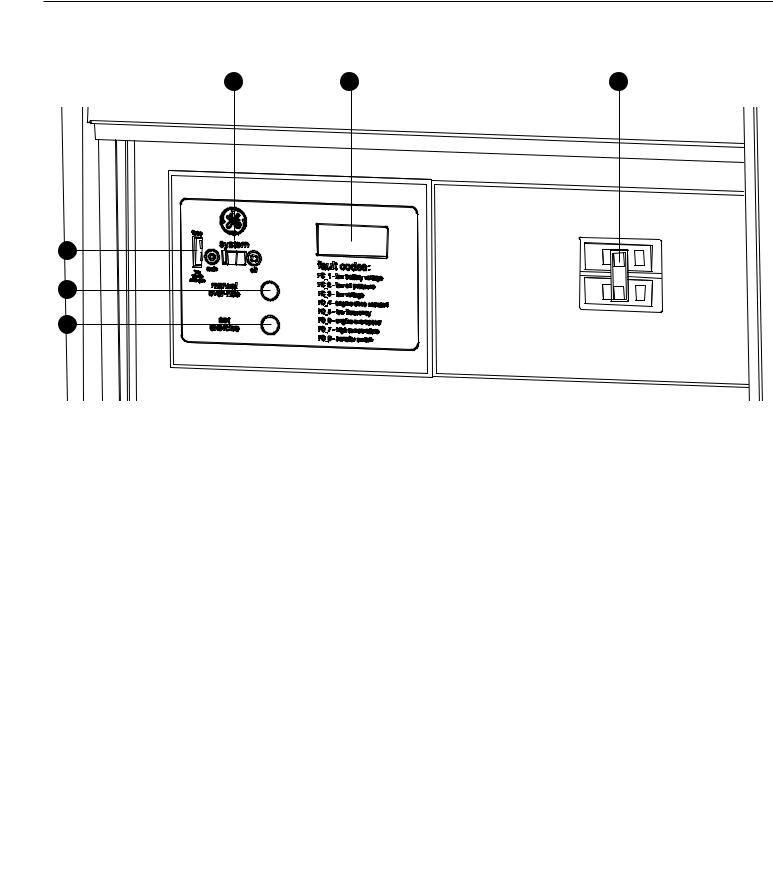
System Control Panel
Compare this control panel illustration with your generator to familiarize yourself with the location of these important controls:
D E F
C |
|
|
for |
B |
|
|
|
A |
|
|
|
|
|
|
|
A - SET EXERCISE— Used to set the exercise cycle start |
the engine stabilize internal temperatures, shuts off the |
||
|
|
Not |
generator, and waits for the next utility power outage. |
time and day-of-the-week. Exercise cycle only occu s in |
|||
AUTO mode. |
|
• “OFF” position turns off running generator, prevents |
|
B – MANUAL OVER-RIDE— With system switch in AUTO |
unit from starting and resets any detected faults. |
||
position, push the manual over-ride switch to start the |
E - Digital Display — Displays the total number of hours |
||
generator. To turn off the generator, push and hold the |
the generator has been running and fault codes. Used |
||
manual over-ride switch again until engine stops. |
to schedule maintenance tasks and for troubleshooting |
||
C - 15 Amp Fuse — Protects the home generator DC control |
operational problems with the home generator. A |
||
|
|
Reproduction |
|
circuits. If the fuse has ‘blown’ (melted open) or was |
constant number displayed indicates the total hours of |
||
removed, the engine cannot crank or start. Replace the |
operation. Fault conditions will flash “FC” followed by a |
||
fuse using only an identical ATO 15A fuse. |
fault code number. All fault conditions are described in |
||
D - System Switch — This two-position switch is the most |
Fault Detection System. |
||
important control on the system and is used as follows: |
F - Circuit Breaker — Protects the generator from shorts and |
||
• “AUTO” position is the normal operating position. If a |
other over-current conditions. Must be ON to supply power |
||
|
utility power outage is sensed, the system will start the |
to the automatic transfer switch. |
|
generator. When utility power is restored, AUTO lets
12

Access Ports
The home generator is equipped with an enclosure that has |
Each home generator is suppied with a set of identical keys. |
||||
several access doors. The doors are named for a significant |
These keys fit the locks that secure the access doors. |
||||
component located behind them, as follows: |
To open access door: |
||||
A |
Control Panel door |
||||
1. Insert key into lock of access door handle and turn |
|||||
B Fuel Inlet Port (shown for reference) |
|||||
key one quarter turn counterclockwise. |
|||||
C |
Oil Drain door |
||||
2. Grasp door’s handle and turn one quarter turn |
|||||
D |
Exhaust Port (shown for reference) |
||||
counterclockwise to open. Remove key. |
|||||
E |
Oil Fill door |
To close access door: |
|||
|
|
||||
|
WARNING Contact with muffler and engine parts could result in |
1. Close door and turn door’s handle one quarter |
|||
|
serious burns. |
||||
|
turn clockwise. |
||||
|
|
||||
• |
DO NOT touch hot parts and AVOID hot exhaust gases. |
2. Insert key into lock of door handle and turn key one |
|||
quarter turn clockwise. Remove key. |
|||||
• |
Allow equipment to cool before touching. |
||||
Additional f |
rce may be required to fully close and |
||||
|
|
||||
The oil and control panel doors must be installed whenever |
|||||
lock |
he |
rs because they create a pressurized seal |
|||
the unit is running to assure proper cooling, reduce noise, |
for |
he generat enclosure. |
|||
and for added safety. |
for |
|
|
|
Not |
|
Reproduction |
A |
B |
C |
D |
E |
13
Operation
Important Owner’s Considerations
Engine Oil
NOTICE Any attempt to crank or start the engine before it has been properly serviced with the recommended oil will result in equipment failure.
•Refer to Maintenance in the operator’s manual and engine manual for oil fill information.
•Damage to equipment resulting from failure to follow this instruction will void engine and generator warranty.
 WARNING Battery posts, terminals and related accessories contain lead and lead compounds, chemicals known to the State of California to cause cancer and reproductive harm. Wash hands after handling.
With the battery installed, all wiring to transfer switch and home generator completed, utility power supplied to the automatic transfer switch, and the unit in AUTO mode, the battery receives a trickle charge while the engine is not
This engine is shipped from the factory pre-run and filled |
|
running. The trickle charge cannot be used to recharge a |
|
with synthetic oil (API SJ/CF 5W-30). This allows for system |
|
battery that is completely discharged. |
|
operation in a wide range of temperature and climate |
|
15 Amp Fuse |
|
conditions. Before starting the engine, check oil level as |
|
The generator’s 15 Amp fuse is critical to correct system |
|
described in the engine manual. |
|
|
|
|
|
pe ation. The 15 Amp fuse was removed at the factory to |
|
Battery |
|
|
|
|
|
prevent the un fr m starting during shipping. Your installer |
|
The installer must supply a valve-regulated, rechargeable |
|
will ensure he fuse s properly installed upon completion of |
|
12 volt DC starting battery. See Battery in Final Installa |
|
the installa ion. |
|
Considerations in the installation manual. Installer |
for |
||
must connect battery charge wire (wire #13) to p sitive |
|
|
|
battery terminal! |
Not |
|
|
Automatic Operation |
|
|
|
|
|
|
|
|
|
|
|
To select automatic operation, do the following: |
|
|
|
|
CAUTION With the system switch set to AUTO, the engine may |
||
|
|
|
|
1. Confirm 15 Amp fuse is installed in control panel. |
|
crank and start at any time without warning. |
|
2. Set the main distribution panel circuit breaker that |
|
• To prevent possible injury that may be caused by such sudden |
|
sends utility voltage to the transfer switch to ON. |
|
||
|
Reproductionstarts, always set the system switch to OFF if performing |
||
3. Set the generator’s circuit breaker to its ON position. |
|
maintenance on the system. |
|
4. Set the control panel system switch to AUTO. |
|
||
|
• Remove the 15 Amp fuse before working on or around the |
||
|
|
|
generator or transfer switch. |
14

Checking Automatic Operation
To check the system for proper automatic operation, proceed as follows:
1.Turn OFF the service disconnect or main distribution panel circuit breaker sending power to the automatic transfer switch.
When utility voltage is lost and the sensor has timed out, the engine will crank and start. Let the system go through its entire automatic operation sequence.
2.With generator output supplying its loads, turn ON the service disconnect or main distribution panel circuit breaker that supplies utility power to the automatic transfer switch.
3.The automatic transfer switch will transfer loads back to utility power after a 5 minute minimum run time and utility power is available.
4.The generator will run for one additional minute for engine cool down, then will shut down.
If utility is restored and generator does not shut down after 10 minutes, set system switch to OFF and contact your installer or local service center.
This completes the test procedures for automatic operation. The home generator will now start automatically and will supply power to the transfer switch when utility power is lost.
Setting Exercise Timer
The home generator is equipped with an exercise timer hat |
|
To perform he Set Exercise procedure: |
||
will start and exercise the system once every seven days. |
|
1. Choose he day and time you want your home |
||
During this exercise period, the unit runs for appr |
xima ely |
for |
generator to exercise. |
|
20 minutes and then shuts down. Electrical load transfer |
|
2. On that day and time, press and hold “SET EXERCISE” |
||
DOES NOT occur during the exercise cycle (unless an utility |
|
|||
|
|
for three seconds. |
||
power outage occurs). |
|
|
|
|
|
|
|
|
|
A button on the control panel is labeled “SETNotEXERCISE” (see |
|
The “Set Exercise” display will illuminate then turn off |
||
System Control Panel). The specific day and the specific |
|
|
to confirm that the exercise timer has been set. Then |
|
|
|
release the button. |
||
time of day this button is pressed is programmed into the |
|
|
||
|
|
The unit will crank and run the exercise cycle. During |
||
control board memory. This date and time is th |
us d to |
|
|
|
automatically initiate the system exercise cycle. The “SET |
|
|
the cycle, “Set Exercise” will illuminate. |
|
EXERCISE” legend on the control panel will flash until the set |
|
|
Once the exercise cycle is complete, the unit will turn |
|
exercise cycle is set. |
|
|
|
|
Reproductionoff and “Set Exercise” will no longer be displayed.
The exercise cycle may be discontinued at anytime by turning the System Switch to OFF.
3. The unit will then start and run it’s 20 minute exercise cycle.
For example, if you press SET EXERCISE on Sunday morning at 10:00 AM, the unit will run an immediate exercise cycle and an exercise cycle every following Sunday at 10:00 AM (+/- 1/2 hour).
“Set Exercise” will only work if the unit is in the AUTO mode and this exact procedure is followed. The exerciser will need to be re-set if the 15 Amp fuse is removed or changed, or if the starting battery is disconnected.
If you want to change the day and time the unit exercises, simply perform the “Set Exercise” procedure at the exact weekday and time you want it to take place.
Generator will not exercise if timer is not set.
15

Maintenance
Servicing the System
Before performing any generator maintenance, always perform the following steps:
1.Set generator’s circuit breaker to its OFF position.
2.Set control panel system switch to OFF.
3.Remove 15 Amp fuse from control panel.
4.Utility voltage is present at generator control panel.
Disconnect power before servicing control panel by removing the fuses from the transfer switch.
5.After all servicing has been completed, replace fuses in transfer switch, replace 15 Amp fuse in control panel, set system switch and circuit breaker ON and reset exercise timer. See Setting Exercise Timer
in Operation.
Low frequency |
ReproductionFC 5 |
||
Fault Detection System |
|
|
|
|
|
for |
|
The generator may have to run for long periods of time |
|
Reset Fault Detecti n System |
|
with no operator present. For that reason, the system is |
|
The pera or must reset the fault detection system each time |
|
|
Not |
|
|
equipped with sensors that automatically shut down he |
|
it activates. To do so, place the control panel system switch |
|
generator in the event of potentially damaging condi ions, |
|
in the OFF position for 30 seconds or more. Remedy the |
|
such as low oil pressure, high temperature, over speed, and |
|
fa lt ondition, then return the home generator to service |
|
other conditions. |
|
|
by placing the system switch in the AUTO position, installing |
The generator’s control panel has a digital display that |
|
the 15 Amp fuse, and resetting the exercise timer. See Setting |
|
shows fault codes, like “FC_1”. The table below lists the |
|
Exercise Timer in Operation. |
|
detected fault, the fault code as displayed the cont ol |
|
L w Battery Voltage (FC_1) |
|
panel. |
|
|
|
|
|
This fault is indicated by fault code FC_1. This condition |
|
|
|
|
|
Fault Description |
Fault Codes |
|
|
|
occurs if the generator cannot start because the starting |
||
Low battery voltage |
FC 1 |
|
battery output power is below that needed to crank the |
Low oil pressure |
FC 2 |
|
engine. Causes for this problem may be a faulty battery or |
|
|
|
battery charge circuit. |
Low voltage |
FC 3 |
|
|
|
To remedy the problem, contact your local service center to |
||
|
|
|
|
Engine does not start |
FC 4 |
|
|
|
check the battery charge output. Remove the 15 Amp fuse |
||
|
|
|
|
|
|
|
|
|
|
|
and disconnect the battery from the generator. Take the |
Engine overspeed |
FC_6 |
|
|
|
battery to a local battery store for analysis. |
||
|
|
|
|
High temperature |
FC_7 |
|
Reinstall the battery (replace if necessary - see Battery in |
|
|
|
|
Transfer switch fault |
FC_8 |
|
|
|
Final Installation Considerations in the installation manual). |
||
Then reset the fault detection system, as described earlier.
16
Low Oil Pressure (FC_2) |
|
|
Low Frequency (FC_5) |
||
This fault is indicated by fault code FC_2. The unit is equipped |
This fault is indicated by fault code FC_5. This feature |
||||
with an oil pressure switch that uses normally closed |
|
|
protects devices connected to the transfer switch by shutting |
||
contacts held open by engine oil pressure during operation. |
|
the generator down if the engine runs slower than 55 Hz for |
|||
Should oil pressure drop below the 8 psi range, switch |
|
|
three seconds. |
|
|
contacts close and the engine is shut down. |
|
|
This condition is caused by a failed engine component or by |
||
To remedy the low oil pressure condition, add the |
|
|
excessive loads on the generator. To remedy the problem, |
||
recommended oil to the FULL mark on the dipstick. |
|
|
contact your installer or an authorized dealer. |
||
If the low oil pressure condition still exists, the engine will |
|
|
Engine Overspeed (FC_6) |
||
start, then shut down again. The fault code will appear. In |
|
|
This fault is indicated by fault code FC_6. This feature |
||
this case, contact an authorized dealer. |
|
|
|||
|
|
protects devices connected to the transfer switch by shutting |
|||
Low Voltage (Generator, FC_3) |
|
|
|||
|
|
the generator down if the engine happens to run faster than |
|||
This fault is indicated by fault code FC_3. This condition |
|
|
the preset limit. |
|
|
is caused by a restriction in the fuel flow, a broken or |
|
|
The overspeed fault is detected as follows: |
||
disconnected signal lead, a failed alternator winding, the |
|
|
• If the generator output frequency is 65-70 Hz, after |
||
control panel circuit breaker is open, or the generator is |
|
|
three seconds, the generator will shut down. |
||
overloaded. |
|
|
• If the generator output frequency is greater than |
||
To remedy the problem, contact your installer or an |
|
|
|||
|
|
70 Hz, the generator will shut down immediately. |
|||
authorized dealer. |
|
|
|||
|
|
This condition is caused by a failed engine component. |
|||
Engine Does Not Start (FC_4) |
|
|
|||
|
|
To emedy the |
blem, c tact your installer or an |
||
This fault is indicated by fault code FC_4. This feature |
|
|
auth rized dealer. |
||
prevents the generator from damaging itself if it con inually |
|
High Tempera ure (FC_7) |
|||
attempts to start in spite of another problem, such as no |
uel |
This fault is indi |
ated by fault code FC_7. The contacts of |
||
supply. Each time the system is directed to start, the unit |
|
|
|||
|
for |
|
|||
will crank for 10 seconds, pause for 10 seconds, and repeat. |
|
the temperature switch are normally open. If the engine |
|||
|
temperat re exceeds approximately 149°C (300°F), the fault |
||||
If the system does not begin producing electricity after |
|
|
|||
|
|
is etected and the engine shuts down. |
|||
approximately 2 minutes, the unit will stop cranking. |
|
|
|||
|
|
|
|
||
Check to make sure the generator’s circuitNotbreaker is in the |
C mmon causes for this condition include running the unit |
||||
ON position in order for the sensing leads to verify that the |
|
with access panels removed, obstructed air inlet or exhaust |
|||
|
port, low oil level, or debris in the engine cylinder cooling fins. |
||||
unit is running. |
|
|
|||
|
|
To resolve the problem, let the engine cool down and remove |
|||
The most likely cause of this problem is no fu l su ly. Check |
|||||
any accumulated debris and obstructions. Ensure that all |
|||||
the internal and external fuel shut off valves to nsure th |
y |
|
|||
|
access panels are installed whenever the unit is running. |
||||
are fully open. Other causes could be failed spark plug(s), |
|
|
|||
|
|
Transfer Switch Fault (FC_8) |
|||
failed engine ignition, or the engine air filter is clogged. You |
|
||||
may need to contact your installer for assistance if you can’t |
This fault is indicated by fault code FC_8 (if transfer switch is |
||||
remedy these problems. |
|
|
|
|
|
Reproductionequipped with fault detection).
The most likely cause of this fault is a blown fuse in the transfer switch. To remedy the problem, contact your installer or an authorized dealer.
17
Generator Maintenance
The generator warranty does not cover items that have been subjected to operator abuse or neglect. To receive full value from the warranty, the operator must maintain the system as instructed in the engine operator’s manual.
All adjustments should be made at least once each season. Follow the requirements in the engine operator’s manual.
Generator maintenance consists of keeping the unit clean. Operate the unit in an environment where it will not be exposed to excessive dust, dirt, moisture or any corrosive vapors. Cooling air louvers on the enclosure must not become clogged with snow, leaves, or any other
foreign material. To prevent generator damage caused by overheating, keep the enclosure cooling inlets and outlets clean and unobstructed at all times.
Check the cleanliness of the unit frequently and clean when dust, dirt, oil, moisture or other foreign substances are visible on its exterior/interior surface. Inspect the air inlet and outlet openings inside and outside the enclosure to ensure air flow is not blocked.
DO NOT use direct spray from a garden hose to clean generator. Water can enter the engine and generator and cause problems.
Engine Oil
The engine is filled with synthetic oil (API SJ/CF 5W-30). This allows for system operation in the widest range of temperature and climate conditions.
The use of synthetic oil does not alter the required oil change |
for |
|||
intervals described in the engine operator’s manual. |
|
|||
|
|
Not |
||
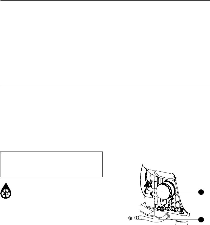
Changing Engine Oil |
|
|||
|
|
Shown here is the oil drain hose (B) and the oil filter location |
||
|
CAUTION Avoid prolonged or repeated skin contact with used |
|||
|
(A) for the generator: |
|||
motor oil. |
|
|
||
• |
Used motor oil has been shown to cause skin canc in |
rtain |
|
|
|
laboratory animals. |
|
|
|
• |
Thoroughly wash exposed areas with soap and water. |
|
|
|
|
|
Reproduction |
||
KEEP OUT OF REACH OF CHILDREN. DON’T POLLUTE. |
|
|
CONSERVE RESOURCES. RETURN USED OIL TO |
A |
|
COLLECTION CENTERS. |
||
|
1.Set control board system switch to OFF.
2.Remove 15 Amp fuse from control panel.
3.Place oil drain hose into an approved container.
4. Remove brass fitting from end of drain hose. |
B |
|
Change oil while the engine is still warm from running, as described in the engine operator’s manual.
5. When oil has drained, replace brass fitting on hose. 6. Add oil. See below.
18
To fill your engine with oil:
Follow the synthetic oil grade recommendation and oil fill instructions given in the engine operator’s manual.
If all engine servicing is complete, replace 15 Amp fuse in control panel and reset exercise timer. See Setting Exercise Timer in Operation.
NOTICE Any attempt to crank or start the engine before it has been properly serviced with the recommended oil will result in equipment failure.
•Refer to Maintenance in the operator’s manual and engine manual for oil fill information.
•Damage to equipment resulting from failure to follow this instruction will void engine and generator warranty.
Battery
Servicing of batteries is to be performed or supervised |
WARNING Ba ery p sts, terminals and related accessories |
||
by personnel knowledgeable of batteries and the |
contain lead and lead compounds, chemicals known to the State |
||
required precautions. Keep unauthorized personnel away |
of California to ause cancer and reproductive harm. Wash hands |
||
|
Not |
for |
|
from batteries. |
after handling. |
|
|
|
|
||
Servicing the Battery |
|
|
|
|
|
|
|
If it is necessary to service the battery, proce as follows: |
|
|
|
1. Set control board system switch to OFF. |
|
|
|
2. Remove 15 Amp fuse from control panel. |
|
|
|
3. Service or replace battery as required. See Battery |
|
C |
|
in Final Installation Considerations in the installation |
|
||
|
Reproduction |
|
|
manual for specific battery needed. |
|
|
|
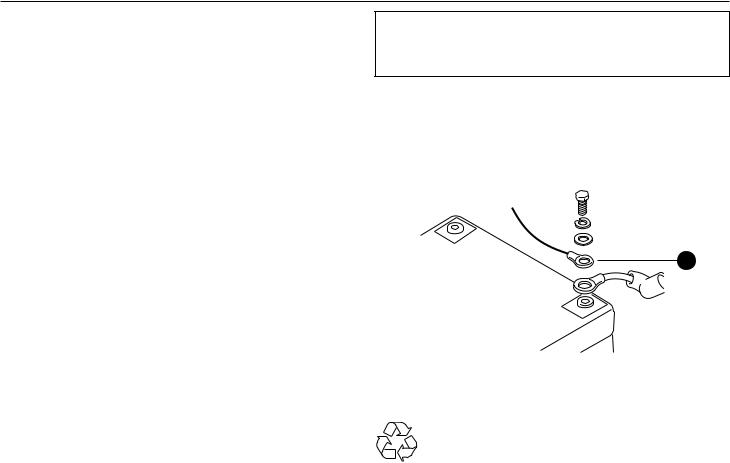
4.Connect red battery cable to battery positive terminal (indicated by POSITIVE, POS, or (+)).
5. |
Connect the battery charge wire (wire #13) shown |
8. Reinstall 15 Amp fuse in control panel. |
|
|
as (C) to the battery positive terminal (indicated by |
||
|
9. Set generator’s system switch to AUTO. |
||
|
POSITIVE, POS, or (+)): |
||
|
10. Reset exercise timer. See Setting Exercise Timer. |
||
6. |
Connect black negative battery cable to negative |
||
DON’T POLLUTE. CONSERVE RESOURCES, RETURN |
|||
|
battery terminal (indicated by NEGATIVE, NEG, or (-). |
||
7. |
Ensure hardware on both positive and negative |
USED BATTERY TO RECYCLING COLLECTION CENTER. |
|
|
battery terminals is secure and fully isolated.
19

Charging the Battery
If it is necessary to charge the battery, proceed as follows: 1. Set control board system switch to OFF.
2. Remove 15 Amp fuse from control panel.
3. Disconnect negative battery cable from negative battery terminal (indicated by NEGATIVE, NEG, or (-)).
NOTICE Failure to disconnect negative battery cable will result in |
|
||
CAUTION With the system switch set to AUTO, the engine may |
|||
equipment failure. |
|||
crank and start at any time without warning. |
|||
• |
DO NOT attempt to jump start the generator. |
||
|
|||
• |
Damage to equipment resulting from failure to follow this |
• To prevent possible injury that may be caused by such sudden |
|
|
instruction will void engine and generator warranty. |
||
|
4. Charge battery with battery charger at 2 Amps until |
starts, always set the system switch to OFF if performing |
|
|
maintenance on the system. |
||
battery holds 12 Volts. DO NOT exceed 13.7 volts when charging.
|
WARNING Storage batteries give off explosive hydrogen gas |
|
8. Set generator’s system switch to AUTO. |
|
|
during recharging. |
|
|
9. Reset exercise timer. See Setting Exercise Timer. |
|
Slightest spark will ignite hydrogen and |
|
||
|
|
|
||
|
cause explosion. |
|
|
|
|
Battery electrolyte fluid contains acid and is |
for |
||
|
extremely caustic. |
|
|
|
Contact with battery contents will cause severe chemical burns. |
|
|||
A battery presents a risk of electrical shock and high short |
|
|||
circuit current. |
|
|
||
• |
DO NOT dispose of battery in a fire. Recycle battery. |
|
||
• |
DO NOT allow any open flame, spark, heat, or lit cigare during |
|||
|
and for several minutes after charging a battery. |
|
||
|
|
|
||
• |
DO NOT open or mutilate the battery. |
|
|
|
• |
Wear protective goggles, rubber apron, rubber boots and |
|
|
|
|
rubber gloves. |
|
|
|
• |
Remove watches, rings, or other metal objects. |
|
|
|
• |
Use tools having insulated handles. |
Not |
|
|
|
|
|
||
|
|
|
|
|
Cleaning the Generator |
|
|
|
|
|
|
|
||
NOTICE Improper treatment of generator can damage it and |
|
3. Clean generator as desired. |
||
shorten its life. |
|
|
• Use a damp cloth to wipe exterior surfaces clean. |
|
|
|
|
|
|
• |
|
Reproduction |
||
DO NOT expose generator to excessive moisture, dust, dirt, or |
|
• Use a soft, bristle brush to loosen caked on dirt, etc. |
||
|
corrosive vapors. |
|
|
|
• DO NOT insert any objects through cooling slots. 1. Set control board system switch to OFF. 2. Remove 15 Amp fuse from control panel.
20
When Calling for Assistance
You must have the following information at hand if it is necessary to contact a local service center regarding service or repair of this unit:
1.Obtain the unit Model Number and Serial Number from the unit ID label. See Controls for location of the label or refer to the information recorded on the inside front cover of the installation manual.
2.Obtain the engine identification numbers from the engine label. See the engine operator’s manual for location of this information. Please note that several different engines are described in the engine manual, so your engine may vary from that shown.
Storage |
Reproduction |
|
|
||
|
|
for |
The home generator system is designed for long term service |
||
as a backup generator. There is no need to take any storage |
|
|
precautions. However, if it becomes necessary to take the |
|
|
system out of service for an extended period, call Technical |
|
|
|
Not |
|
Services at 888 575 8226, between 8:00 AM and 5:00 PM CT for specific recommendations. Refer to the engine perat r’s manual for additional information.
21
Troubleshooting
Problem |
|
|
Cause |
|
Correction |
|
|
|
|
|
|
|
1. |
Circuit breaker open or defective. |
1. |
Reset or replace circuit breaker. |
|
Engine is running, but no AC output |
2. |
Fault in generator control panel. |
2. |
Contact local service facility. |
|
is available. |
3. |
Poor wiring connections or |
3. |
Check and repair or contact |
|
|
|||||
|
|
defective transfer switch. |
|
local service facility. |
|
|
|
|
|
|
|
|
1. |
Short circuit in a connected load. |
1. |
Disconnect shorted |
|
|
|
|
|
|
electrical load. |
|
2. |
Generator is overloaded. |
2. |
Turn off one or more loads. |
|
Engine runs good at no-load but “bogs |
3. |
Shorted generator circuit. |
3. |
Contact local service facility. |
|
|
|
for |
|
|
|
Loss of power on circuits. |
Reproduction |
|
|
||
down” when loads are connected. |
4. |
Fuel pressure mixtu is |
4. |
See Gaseous Fuel System in the |
|
|
|
incorrect. |
|
i stallation manual. |
|
|
5. |
Kinked |
uel line between regulat r |
5. |
Remove kink. Replace |
|
|
and engine. |
|
if necessary. |
|
|
1. |
15 Amp fuse missing or blown. |
1. |
Install (new) 15 Amp fuse. |
|
|
|
|
|
|
See System Control Panel. |
Engine will not start; or starts and |
2. |
Fuel supply turned off or depleted. |
2. |
Open fuel valve(s); check |
|
runs rough. |
|
|
|
|
propane tank. |
|
3. |
Failed batte y. |
3. |
Replace battery. |
|
|
Not4. Clogged air filter. |
4. |
Clean or replace air filter. |
||
|
1. |
Fu l su |
ly turned off or depleted. |
1. |
Check fuel valves, fill |
|
|
|
|
||
Engine shuts down during operation. |
2. |
Fault code indicated. |
|
propane tank. |
|
|
2. |
Refer to Fault Detection System. |
|||
|
|
|
|
||
|
|
|
|
|
|
|
1. |
Generator circuit breaker is open. |
1. |
Reset circuit breaker. |
|
|
2. |
Transfer switch problems. |
2. |
See transfer switch manual. |
|
|
|
|
|
|
|
22

Warranty
Limited Warranty
Briggs & Stratton Power Products Group, LLC will repair or |
FITNESS FOR A PARTICULAR PURPOSE, ARE LIMITED TO ONE |
||
replace, free of charge, any part(s) of the equipment that |
YEAR FROM PURCHASE, OR TO THE EXTENT PERMITTED BY |
||
is defective in material or workmanship or both. Travel |
LAW. ANY AND ALL IMPLIED WARRANTIES ARE EXCLUDED. |
||
expenses are reimbursed as specified under the Briggs |
LIABILITY FOR INCIDENTAL OR CONSEQUENTIAL DAMAGES |
||
& Stratton Warranty Guidelines document to authorized |
IS EXCLUDED TO THE EXTENT EXCLUSION IS PERMITTED |
||
Briggs & Stratton dealers for performing applicable warranty |
BY LAW. Some states or countries do not allow limitations |
||
repair work. This warranty is effective for the time periods |
on how long an implied warranty lasts, and some states |
||
and subject to the conditions stated below. For all warranty |
or countries do not allow the exclusion or limitation of |
||
service, find the nearest Authorized Service Dealer in our |
incidental or consequential damages, so the above limitation |
||
dealer locator map at BRIGGSandSTRATTON.com. |
and exclusion may not apply to you. This warranty gives |
||
|
|
you specific legal rights and you may also have other rights |
|
THERE IS NO OTHER EXPRESS WARRANTY. IMPLIED |
which vary from state to state or country to country. |
||
for |
|||
WARRANTIES, INCLUDING THOSE OF MERCHANTABILITY AND |
|||
Warranty Period |
|
||
|
|
||
|
|
|
|
|
5 years or 1,800 h |
urs, whichever comes first |
|
|
Not |
|
|
The warranty period begins on the date of purchase by the |
NO WARRANTY REGISTRATION IS NECESSARY TO OBTAIN |
||
first retail consumer and continues for the riod of time |
WARRANTY ON BRIGGS & STRATTON PRODUCTS. SAVE YOUR |
||
stated above. |
|
PROOF OF PURCHASE RECEIPT. IF YOU DO NOT PROVIDE |
|
|
|
PROOF OF THE INITIAL PURCHASE DATE AT THE TIME |
|
|
|
WARRANTY SERVICE IS REQUESTED, THE MANUFACTURING |
|
|
|
DATE OF THE PRODUCT WILL BE USED TO DETERMINE THE |
|
ReproductionWARRANTY PERIOD.
Warranty Terms continue on next page
is a trademark of General Electric Company and is under license by Briggs & Stratton Power Products Group, LLC.
Copyright © 2010. All rights reserved. No part of this material may be reproduced or transmitted in any form without the express written permission of Briggs & Stratton Power Products Group, LLC.
23

About Your Warranty
We welcome warranty repair and apologize to you for |
|
|
• Other Exclusions: This warranty excludes starting |
|||
being inconvenienced. Any authorized service dealer may |
|
|
battery, accessory parts, wear items such as oil |
|||
perform warranty repairs. Most warranty repairs are handled |
|
gauges, o-rings, filters, fuses, or spark plugs, etc., or |
||||
routinely, but sometimes requests for warranty service |
|
|
|
damage or malfunctions resulting from accidents, |
||
may not be appropriate. For example, warranty service |
|
|
|
abuse, modifications, alterations, or improper |
||
would not apply if equipment damage occurred because |
|
|
|
servicing or freezing or chemical deterioration. |
||
of misuse, lack of routine maintenance, shipping, handling, |
|
|
This warranty excludes failures due to acts of |
|||
warehousing or improper installation. Similarly, the warranty |
|
|
God and other force majeure events beyond |
|||
is void if the manufacturing date or the serial number on |
|
|
|
the manufacturers control. And this warranty |
||
the equipment has been removed or the equipment has |
|
|
|
excludes used, reconditioned, and demonstration |
||
been altered or modified. During the warranty period, the |
|
|
|
equipment; equipment used for prime power in |
||
authorized service dealer, at its option, will repair or replace |
for |
place of utility power, equipment used in mobile |
||||
any part that, upon examination, is found to be defective |
|
or rental applicatio |
s, a d equipment used in life |
|||
under normal use and service. This warranty will not cover |
support appl cati |
s. |
||||
the following repairs and equipment: |
|
|
Enclosure s warranted against surface rust and |
|||
|
|
|
orros on for the first year of the warranty period. |
|||
• Normal Wear: Outdoor Power Equipment and |
|
Surfa e rust and corrosion is defined as any rust or |
||||
|
orrosion that has penetrated the paint but has not |
|||||
engines, like all mechanical devices, needs peri dic |
|
|
penetrated through the metal substructure. |
|||
parts and service to perform well. This warranty d |
es |
|
|
Enclosure is warranted against rust-through for the |
||
not cover repair when normal use has exhausted the |
|
|
||||
|
|
first two years of the warranty period. |
||||
life of a part or the equipment. |
Not |
|
|
Rust-through is defined as rust or corrosion that |
||
|
|
|
has penetrated completely through the paint and |
|||
|
|
|
metal substructure. |
|||
• Installation and Maintenance: This warranty does |
|
|
||||
|
|
Enclosure is not warranted for surface rust or |
||||
not apply to equipment or parts that have b |
|
|
|
|||
|
|
|
corrosion or complete rust-through that may result |
|||
subjected to improper or unauthorized installation |
|
|
||||
|
|
due to improper installation, damage to painted |
||||
or alteration and modification, misus , glig nc |
, |
|
|
surfaces that compromise the paint’s corrosion |
||
accident, overloading, overspeeding, improper |
|
|
|
prevention properties, or if the unit is installed in |
||
maintenance, repair or storage so as, in our |
|
|
|
environments that expose the generator to high levels |
||
judgment, to adversely affect its performance and |
|
|
of corrosive agents. |
|||
|
Reproduction |
|||||
reliability. This warranty also does not cover normal |
|
|
|
|
||
maintenance such as adjustments, fuel system |
|
|
Warranty terms effective November 1, 2009 - replaces all undated Warranties and |
|||
cleaning and obstruction (due to chemical, dirt, |
|
|
Warranties dated before November 1, 2009 207905E, Rev. D, 2 November 2009 |
|||
|
|
|
|
|
||
carbon, lime, and so forth).
24
 Loading...