


GTS21SCXASS
GE GTS21SCXASS, GTS21SBXASS, GTS21KCXAWW, GTS21KCXABB, GTS21KBXAWW Owner’s Manual
...
¢)
¢)
4..0
GEPpp/iances.com
Safety Instructions ............ 2-4
Operating Instructions
Automatic Icemaker ............. 9
Controls ....................... 5
Crispers and Pans ............. 7, 8
Shelves and Bins ................ 6
Care and Cleaning
Care and Cleaning .......... 10, 11
Replacing the i,ight Bulb ........ 11
Installation Instructions
Icemaker Installation ........ 13-16
Preparing to Install
the Refrigerator ............... 12
Reversing the Door Swing .... 21-25
Water i Jne Installation ....... 17-21
Moo#Is G7"t-12 I, GTL2 l
and G7"5"2l
Congdlateur supdrieur
Rdfrigdrateurs
La section frangaise commence _ la page 32
Congelador superior
®
Troubleshooting Tips ....... 26-29
Normal Operating Sounds ....... 26
Consumer Support
Consumer Support ..... Back Cover
Warranty fi)r
Canadian Customers ............ 30
Warranty for U.S. Customers ..... 31
Note to Installer - Be sure to leave
fllese instructions wifll file Consumer
Note to Consumer - Keep these
instructions f_n"fl_alre reference.
Note/_ l'installateur - Assurez-vous
de laisser ces insuucfions au
consolnlna[eilI-
Note au consommateur -
Conservez ces instructions pour
r_f_rence fl_U_re.
Nora al instalador - asegfirese
de dejar estas insmmciones con el
cons tltIlidoI_
Nora aL!consumidor - Conserve
estas instrucciones para refe.rencia fimm_.
Refrigeradores
Lasecci6n en espa_o/empieza en/apagina 65
Writethemodelandserial numbershere:
Model #
Serial #
Find these numbers on the gray label
on the lef_ side, near the top of the
refrigerator compartment.
_9707733P00_ 49-60505-2 04-09 JR

iMPORTANTSAFETYINFORMATION.
READALLiNSTRUCTiONSBEFOREUSING.
A WA
Use this appliance only for its intended purpose as described in this Owner's Manual
,!
m
SAFETYPRECAUTIONS
When using electrical appliances, basic safety precautions should be followed, including the following:
}}_This refligerator must be properly installed
and located in accordance with the Installation
Instructions before it is used.
Do not allow children to climb, stand or hang
on the shelves in the reflJgerator They could
dmnage the reflJgemtor and seriously i_jure
themselves.
}}_Do not touch the cold surfitces in the fleezer
compartment when hands are damp or wet.
Skin may stick to these extremely cold surf_tces.
}}_Do not store or use gasoline or other flammable
xapors and liquids in the vicinity of this or any
other appliance.
',_ In refligerators widl automatic icemake_,
avoid contact with the moving parts of the
eiector mechanism, or with the heating element
located on the bottom of the icemaker Do not
place finge_ or hands on the automatic
icemaldng mechanism while the refligemtor
is plugged in.
,,_Keep fingers out of file "pinch point" areas;
clearances between the doors and bet_,veen the
doors and cabinet are necessarily stuN1. Be carefhl
closing doors when chiMren are in the area.
}}_Unplug the refligerator before cleaning and
making repai_.
NOTE:Westronglyrecommendthatanyservicingbe
performedbyaqualifiedindividual
}}{_Setting either or both controls (some models only
have one control) to the 1 (Off) position does not
remove power to the light circuit.
}}{_Do not refleeze flozen foods which have
thawed completely.
2
GEPpp/iance&com
A
OF ,B
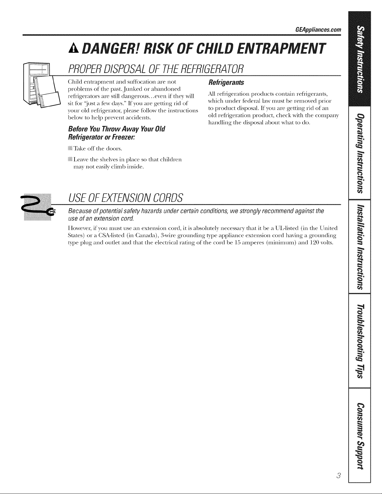
PROPERDISPOSALOFTHEREFRIGERATOR
Child entrapment and suftbcafion are not
problems of the past. Junked or abandoned
refligerators are still dangerous...even if they will
sit fbr 'just a few days." If you are getting rid of
your old refligeratox; please follow the instructions
below to help prevent accidents°
Before You7",hrowAway YourOld
Refrigeratoror Freezer:
} Take off the doors°
}i_i,eave the shelves in place so that children
may not easily climb inside.
Refrigerants
All refrigeration products contain refiigerams,
which under federal law must be removed prior
to product disposal If you are getting rid of an
old refiigeradon product, check with the company
handling the disposal about what to do.
USEOFEXTENSIONCORDS
Because of potential safety hazards under certain conditions, we strongly recommend against the
use of an extension cord,
However; if you must use an extension cord, it is absolutely necessary that it be a UL-listed (in the United
States) or a CSA-listed (in Canada), 3-wire grounding type appliance extension cord having a grounding
type plug and outlet and that the elecuJcal rating of the cord be 15 amperes (minimum) and 120 volts.
3

iMPORTANTSAFETYINFORMATION.
READALLiNSTRUCTiONSBEFOREUSING.
A WA
,!
m
HOWTOCONNECTELECTRICITY
Do not, under any circumstances, cut or remove the third (ground) prong from the power cord,
For personal safety, this appliance must be properly grounded,
The power cord of dlis appliance is equipped widl
a 3-prong (grounding) plug which mates wit1 a
standard 3-prong (grotmding) wall outlet to
minimize the possibility of elecuic shock hazard
fiom this appliance°
Have the wall oudet and drcuit checked by a
qualified electrician to make sure the outlet is
properly grounded.
Where a standard 2-prong wall oudet is
encotmmred, it is your pet_onN responsibility and
obligadon to have it replaced with a properly
grounded 3-prong wall outlet.
The refligerator should ah,vays be plugged into its
own individual electrical outlet which has a voltage
rating that matches the rating plate.
This proxides the best performance and also
prevents overloading house wiring circuits which
could cause a fire hazard fiom overheated wires.
Never unplug your refligerator by pulling on the
power cord° Ah,vays g_ip plug firefly and pull
straight out fiom the otlflet.
Repair or replace immediately all power cords flint
have become fiwed or otherwise damaged. Do not
use a cord that shows crocks or abrasion damage
along its length or at either end.
When moving the refligerator away flom the
wall, be careflfl not to roll over or damage the
power cord.
READANDFOLLOWTHISSAFETYINFORMAtiONCAREFULLY.
SAVETHESEINSTRUCTIONS
4
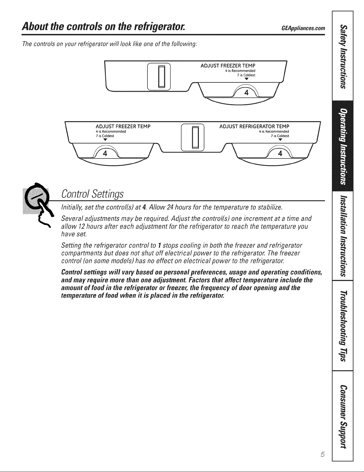
About the controlsonthe refrigerator.
Thecontrols on your refrigerator will looklikeone of the following:
GEApp/iances.com
i _ ADJUST FREEZER TEMP i
I _ | I 4iS Recommended #
I I III ,,sCCdestj
ADJUST FREEZER TEMP _ ADJUST REFRIGERATOR TEMP /
4 is Recommended l I l I 4is Recommended l
7 is Coldest J I I I zis Coldest
v
ControlSettings
Initially, set the control(s) at 4. Allow 24 hours for the temperature to stabilize.
Several adjustments may be required. Adjust the control(s) one increment at a time and
allow 12hours after each adjustment for the refrigerator to reach the temperature you
have set.
Setting the refrigerator control to I stops cooling in both the freezer and refrigerator
compartments but does not shut off electrical power to the refrigerator. The freezer
control (on some models) has no effect on electrical power to the refrigerator.
Control settings will vary based on personal preferences, usage and operating conditions,
and may require more than one adjustment. Factors that affect temperature include the
amount of food in the refrigerator or freezer, the frequency of door opening and the
temperature of food when it is placed in the refrigerator.
5

Aboutthe shelves andbins.
Not all features are on all models,
Rearranging the Shelves
Shelves in the refligerator and fleezer compamnents are adjustable.
Refrigerator Compartment
Half-WidthShelves
One end of the shelf rests on a
molded side-wall support; a bracket
on file oilier end hooks into a track
on file rear cabinet wall.
TOremove:
O Tilt the shelf up at the flont.
0 i,iff the support off and out of the track.
d_Titt up
o- 4
f./---
Toreplace:
0 While tilting the shelf up, insert the top
hook at the back of the shelf in a slot
on the track.
0 Lower the flont of the shelf undl the
bottom of the shelf locks into place.
NOTE:Theshelf to theright of the trackis
designedtohookinto theright-handslot,the
shelf to theleft isdesignedtohookinto the
left-handslot
Freezer Compartment
Toremove:
Lift up the left side of the shelf and
slide it left into the center of the shelf
supports.
Rotate the fight side of the shelf up and
out of the shelf supports.
Toreplace:
il
i _!i!
6
0 HoMing the shelf diagonally; insert the
left end of the shelf into the center of
the shelf supports on the side wail.
0 Insert the right end of the shelf into
the shelf supports on the side wall.
Rest each end of the shelf on the
bottom of the shelf supports.
Aboutthecrispersandpans. C App,ia,ces.com
Not all features are on all models,
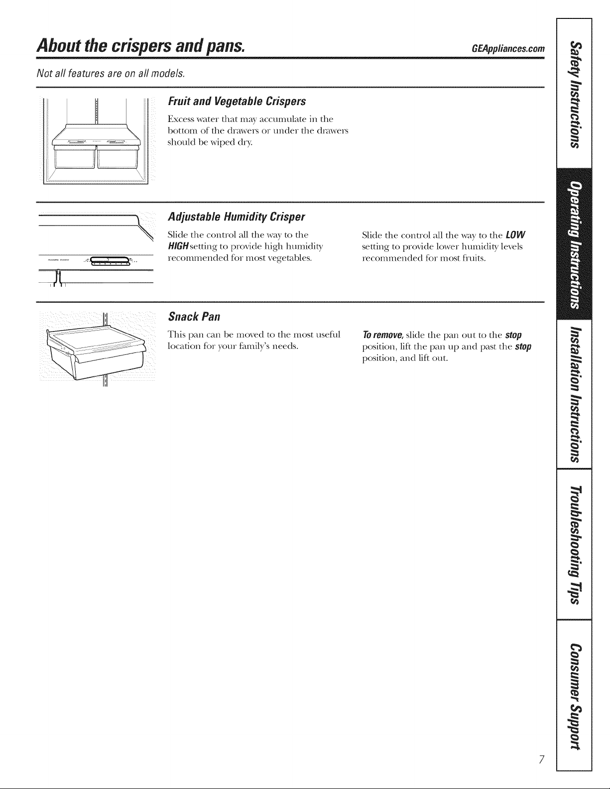
Fruit and Vegetable Crispers
Excess water that may accmmflate in the
bottom of the dra\,ve_ or under the dm\,ve_
shoukt be wiped d_T.
Pdjustab/e Humidity Crisper
Slide the control all the way to the
H/GHsetting to provide high lmmidity
recommended K_r most vegetables.
Snack Pan
Slide the control all the way to the LOW
setting to provide lower humidity levels
recommended fbr most fluits.
This pan can be moved to the most useflfl
location fbr your fhmily's needs.
Toremove,slide the pan out to the stop
position, lif_ the pan up and past the stop
position, and lif_out.
7
Aboutcrisperremoval
Not all features are on all models,
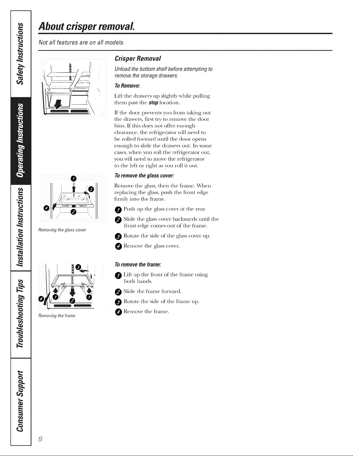
Crisper Removal
ii! I "
Unload the bottom shelf before attempting to
remove the storage drawers.
ToRemove:
l,if_ the drawers tap slightly while pulling
them p_Lstthe stop locafiono
If file door prevents you flom taldng out
the drawea_, first try to rein<we the door
bins° If this does not offbr enough
clearance, the refligemtor will need to
be rolled fbrward until the door opens
enough to slide the drawea_ out. In some
cases, when you roll the refligerator out,
you will need to re(we the refligerator
to the left or right as you roll it ()tat.
Toremovetheglasscover:
Remove the glass, then the flame. _,rhen
replacing the glass, push the flont edge
firefly into the flame.
Removingtheglasscover
Removing the frame
0 Push tap the glass cover at the rein:
0 Slide the glass cover backwards until the
flont edge comes out of the flame.
0 Rotate the side of the glass cover tap.
Remove the glass covea;
Toremove the frame:
0 Lif_ up the flont of the flame using
both hands°
Slide the f}ame fbn,vard.
0 Rotate the side of the flame tap.
O Remove the flame.
8
Abouttheautomaticicemaker. CEA,,,ia.ce .com
A newly-installed refrigerator may take 12-24 hours to begin making ice,
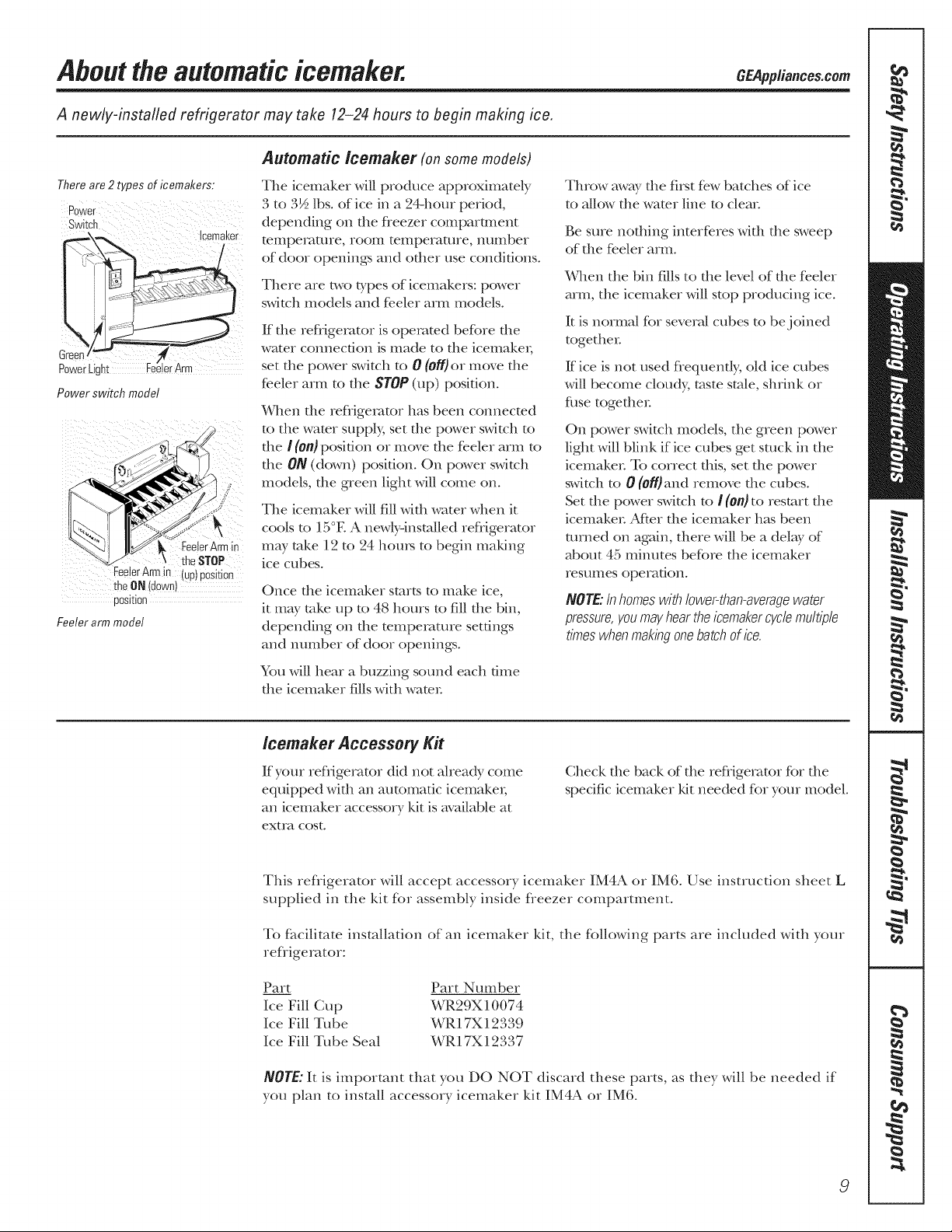
Automatic lcemaker (onsomemodels)
There are 2 types of icemakers:
Power
Switch
_x_. !cemaker
G;)
Po;er
Power switch model
FeelerArmin
FeelerArm n
theON ieowm
ooskion
Feeler arm model
theSTOP
uoJDOSkion
The icemaker will produce approximately
3 to 3½ lbs. of ice in a 24-hour period,
depending on the fleezer compartment
telnperat/]re, rooIll telllperat/lre, ntl[llbei
of door openings and other use conditions.
There are two types of icemakers: power
switch models and fe.eler arIn models.
If tlle refligerator is operated before tile
water connection is made to the icemake_;
set tile power switch to 0 (off) or move the
feeler arI-n to tile STOP(up) position.
¼qlen file refligemtor has been connected
to tile wamr supply, set tlle power switch to
the I (On}posidon or IIlove the feeler arm to
tile ON (down) position. On power swimh
models, die green light will come on.
The icemaker will fill widl water when it
cools to 15°E A new/y-installed refligerator
may rake 12 to 24 hom_ to begin making
ice cubes.
Once file icemaker starts to make ice,
it may rake up to 48 hours to fill file bin,
depending on the mmpemmre settings
and nmnber of door openings.
You will hear a buzzing sound each dine
the icemaker fills with wate,:
Throw away tile first few batches of ice
to allow the water line to clear
Be sure nothing interfe.res with tile sweep
of tile feeler arm.
When the bin fills to the level of tile feeler
arIn, tile icemaker will stop producing ice.
It is normal for several cubes to be joined
together
ff ice is not used flequently; old ice cubes
will become cloudy, taste stole, shrink or
fuse together
On power switch Inodels, tile green power
light will blink if ice cubes get stuck in tlle
icemake_: To correct this, set die power
switch to 0 (0ff)and remove the cubes.
Set tile power switch to / (Oft)to restart die
icemaker After the icemaker has been
turned on again, there will be a del W of
about 45 minutes before tile icemaker
res uIIles operation.
NOTE:Inhomeswithlower@an-averagewater
pressure,youmayheartheicemakercyclemultiple
timeswhenmakingonebatchof lee.
/cemaker Accessory Kit
If your refligerator did not aheady come
equipped with an automatic icemake_;
an icemaker accesso_ T ldt is available at
extra cost.
This refligerator will accept accessory icemaker IM4A or IM6. Use instruction sheet L
supplied in the kit for assembly inside fleezer compamnent.
To facilitate installation of an icemaker kit, the fbllowing parts are included with your
refligerator:
Part Part Number
Ice Fill Cup WR29X10074
Ice Fill Tube WR17X 12339
Ice Fill Tube Seal WR l7X 12337
NOTE:It is important that you DO NOT discard these parts, as they will be needed if
you plan to install accessory icemaker kit IM4A or IM6.
Check tile back of tile refligerator for tile
specific icemaker kit needed for your model.
9
Careandcleaningoftherefrigerator.
Cleaning the Outside
Thedoorhandlesandtrim.Clean with
a clod1 dampened widl soapy water:
Dry with a soR cloth.
Keep theoutsideclean.Wipe with a clean
clod1 ligbdy dampened with kitchen
appliance wax or mild liquid dish
dem_gent. Dry and polish with a clean,
soR clodL
Thestainless steel panels and doorhandles
(on some models) can be cleaned with
Cleaning the Inside
a commercially available stainless steel
cleaner. Do not use appliance wax or polish
on the stainless smel.
Donot wipetherefrigeratorwithasoileddishcloth
orwettowel Thesemayleavea residuethat
canerodethepaint Donotusescouringpads,
powderedcleaners,bleachorcleanerscontaining
bleachbecausetheseproductscanscratchand
weakenthepaintfinish.
Tohelp prevent odors,leave an open box of
baldng soda in file flesh food and fleezer
compartments.
Unplug the refrigerator before cleaning. If this
is not practical, wring excess moisture out
of sponge or cloth when cleaning around
switches, lights or conuols.
Use/,vaiIi}./,vilteI and baking soda solution--
about a tablespoon (15 ml) of baldng soda
to a quart (1 limr) of wam_: Tiffs both cleans
and neutralizes odors. Thoroughly IJnse
and wipe dry.
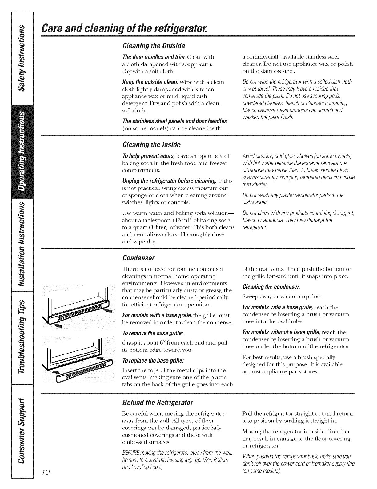
Condenser
There is no need for roudne condenser
cleanings in nomm/home opemdng
environments. Howevei; in environI_Ttents
that may be particularly dusty or greasy; the
condenser should be cleaned periodically
for efficient reflJgemtor operation.
Formodelswitha basegrille,d_e gqille must
be removed in order to clean die condenser
Toremovethebase grille:
Grasp it about 6" flom each end and pull
its bottom edge toward you.
Toreplacethebasegrille:
Insert tlle tops of the metal clips into the
ova/vents, making sure one of the plastic
tabs on tile back of tile grille goes into each
Avoid cleaning cold glass shelves(onsomemodels)
with hot water becausethe extreme temperature
difference maycausethem tobreak.Handleglass
shelvescarefully Bumpingtemperedglasscan cause
it to shatter
Donot washangplasticrefrigeratorpartsinthe
dishwasher
Donotcleanwithangpreductscontainingdetergent,
bleachorammonia.Theymaydamagethe
refrigerator
of die oval vents. Then push die bottom of
the grille fbrward until it snaps into place.
Cleaningthecondenser:
Sweep away or vacuum up dust.
For models win a base grille, reach d_e
condenser by inserting a brush or vacuum
hose into the ova/boles.
For models wiNout a base grille, reach d_e
condenser by inserting a brush or vacuum
hose under tile bottom of the reflJgerator
For best results, use a brush specially
designed for dfis purpose. It is available
at most appliance parts stores.
10
Behind the Refrigerator
Be careflfl when moving the refligerator
away flom the wall. All t),pes of floor
coverings can be damaged, particularly
cushioned coverings and those with
embossed smfaces.
BEFOREmovingtherefrigeratorawayfromthewall,
besuretoadjustthelevelinglegsup.(SeeRollers
andLevelingLegs.)
Pull die refligerator smdght out and return
it to posidon by pushing it straight in.
McMng file refligerator in a side direction
may result in damage to the floor covering
or reflJgerator
Whenpushingtherefrigeratorback,makesureyou
don'trefloverthepowercordoricemakersupplyline
(onsomemodels).

Preparing for Vacation
GEPpp/iance&com
For long V_tCa[ioIIS Of _bsences_ ielnove
food and mlplug the refligeratoT. Move
file refligerator control to file 1 (Off}position
and clean file interior wifll a baking soda
solution of one tablespoon (15 ml) of
baking soda to one quart (1 limr) of wamr
i,eave the doo_ open.
Set the icemaker power switch to file 0 (Off)
position or move the feeler am1 to the STOP
(up) position (depending on model) and
shut off file water supply to file refligemtor
If the temperature can drop below fleezing,
have a qualified servicer drain the water
supply system (on some models) to prevent
serious property damage due to flooding.
Preparing to Move
Secure all loose items such as grille,
shelves and drawexs by taping them
securely in place to prevent damage.
Besuretherefrigeratorstaysin anuprightposition
&ring moving
Replacingthe fightbulb.
Setting either or both controls to 1 (off) does not remove power to the light circuit.
Refrigerator Compartment--Upper tight
A CAUTION:Light_u/_maybeh0t. 0 _epl.ce,,_l,_,,,.ppH.,,cet>,,lt>of
Unplug the refrigerator. _ Plug the refligerator back in.
The bulb is located at the top of file
compamnent near the opening.
the same or lower wattage.
11

st llati
m
rato
I structi
BEFORE YOU BEGIN
Read these instructions completely and carefully.
" IMPORTANT - S.ve hese
instructions if)r local inspector's use.
" IMPORTANT - Obse,ve.ll
governing codes and ordinances.
* Note to Installer - Be sure to leave these
instructions with tile ConsuH-ter
. Note to Consumer - Keep these instructions
for future reference.
* Skill level - Installation of this appliance requires
basic mechanical skills.
* Completion time - Refligerator Installation
15 minutes.
* Proper installation is the responsibility of the
installer.
* Product failure due to improper installation is not
covered under the Warranty.
WATER SUPPLY TO THE ICENIAKER
{ON SOME MODELS)
If the refligerator has an icemakm; it will have
to be connected to a cold water line. AGE water
supply kit (containing robing, slmtoff valve, fittings
and instructions) is available at extra cost flom your
dealer or by visiting our Website at GEAppliances.com
or Parts and Accessories, 800.626.2002.
REFRIG ERATOR LOCATION
" Do not install file refligerator where the mmperamre
will go below 60°F (16°C) because it will not run often
enough to maintain proper temperatures.
" Do not install file refligerator where the mmperatme
will go above 100°F (37°C) because it will not perfbrxn
properly:
- Install it on a floor strong enough to support it flflly
loaded.
Models GTH21,GT/_21and GTS21
CLEARANCES
Allow the ff>llowing clearances fin ease of installation,
proper air circulation and plumbing and electrical
COllllectioIls.
"Sides 1/8" (3 ram)
"Top 1"(25 ram)
"Back 1" (25 ram)
If the refligerator is to be installed next to a wall on the
binge side, allow 5/16" (8 ram) door clearance.
ROLLERS AND LEVELING LEGS
Rollers allow you to mcwe file refligemtor away flom file
wall for cleaning.
Leveling Legs near each flont corner of file refligerat(n;
next to the rollers, shouM be adj usmd if any of the
fbllowing occurs:
" Refligerator wobbles due to flont roller not being firefly
positioned on the floor
" Door(s) do not close easily when opened to 45 °.
NOTE:
" BEFORE moving die refligemtor away flom file wall,
be sure to turn the leveling legs cotmterclockwise so that
the weight of the reflJgerator is fiflly mmsfe.rred to the
flont rolle_.
" The refligemtor will not be level flora flont to back. It
will have a slight backward flit for proper doo>closing.
To adjust the leveling legs,
turn the two flont leveling
legs dockwise to raise the
flont of the refligerator and
counterclockwise to lower it.
__4)iiwi seto
raise
refrigerator
12

Installation instructions
ICENIAKER iNSTALLATiON
BEFORE YOU BEGIN
Read each step thoroughly before proceeding.
CAUTION - U,,pl.:the
Refligerator To eliminate the danger
of electric shock during installation,
you must unplug the refligerator flom
its electrical outlet.
TOOLS YOU WILL NEED
FlatbladeandPhillips Pliers
screwdrivers
PARTS INCLUDED
iNSTRUCTIONS
_] REMOVE THE OUTLET COVER
• Remove the outlet cover
with a fiat-blade screwdriver
Side Back
_PREPARE FOR INSTALLATION
Inside the fleezeL loosen the h,vo mounting screws,
but do not screw them all the way out. If your model
does not have the screws aheady in the fieezer wall,
look for t_,vo plug buttons. Remove the plug buttons
and insert the two Phillips head screws. The screws
should extend approximately 1/2" (13ram) out
flom the fleezer wall
©
2
NO. DESCRIPTION QUANTITY
1 WaterFill Tube 1
2 IceFill Guide 1
3 WaterFill TubeSeal 1
m INSTALL FILL TUBE
• If the refligerator aheady has a
water tube inlet on the back of the
refiigerator, go to Step 2.
• Remove and discard the white plug
flom the lower left back corner of
the fleezer wall.
* Go to the back of the refligerator. Find the small
label in the upper right band corner and peel it
off_Then discard the label.
Peel one side of the paper away _ Seat
flom the water fill tube seal, slide Ir'___
the seal along the tube and affix u -_-o4_._,'X,x
to the back side of the water
robe inlet flange.
Remove the adhesive
bacMng on the opposite side
of the water fill robe sea/and
slide the robe into the hole _
near the top at the back of the refiigeratcn: Fhmly
press on the inlet to secure it to the refligerator
Mounting
screws
3
[-4-]SETPOWER SWITCH TO 0 (off)
Set the icemaker power switch to O (of_). Leave
the power switch in the O (offc) position undl the
refiigerator is connected to the water supply to
prevent premature operation.
_ Holef?r
wiretie
SwitchP°wer ......__+...........- -%
(Appearance may vary)
13
Installation instructions
ICEMAKER
iNSTALLATiON iNSTRUCTiONS (CONT.I
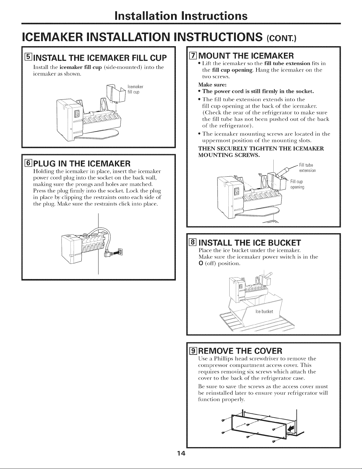
[_INSTALL THE ICEMAKER FiLL CUP
Install tile icemaker fill cup (skte-mounted) into tile
icemaker as shown.
Icemal<er
fill cup
[_PLUG IN THE ICEMAKER
Hokling die icemaker in place, insert tile icemaker
power cord plug into the socket on tile back wall,
maMng sure tile prongs and boles are matched.
Press tile plug firmly into tile socket, i,ock the plug
in place by clipping the resuaints onto each side of
tile plug. Make sure tile restraints click into place.
[-/-]MOUNT THE ICEMAKER
, Lift tile icemaker so tile fill tube extension fits in
tile fir cup opening. Hang tile icemaker on tile
two screws.
Make sure:
*The power cord is still firmly in the socket.
* Tile fill tube extension extends into the
fill cup opening at tile back of tile icemaker
(Check tile rear of file refligerator to make sure
tile fill tube has not been pushed out of tile back
of tile refligerator).
* Tile icemaker Illotlnfing sclews are located in tile
uppermost position of tile mounting slots.
THEN SECURELY TIGHTEN THE ICEMAKER
MOUNTING SCREWS.
[_ INSTALL THE ICE BUCKET
Place tile ice bucket under tile icemaker.
Make sure tile icemaker power switch is in tile
0 (off) position.
_]REMOVE THE COVER
Use a Phillips head screwdriver to remove tile
conlpressor compartulent access cover. This
requires removing six screws which attach tile
cover to tile back of tile refligerator case.
Be sure to save tile screws as the access cover must
be reinstalled later to ensure your refligerator will
flmcdon properl>
14
Installation instructions
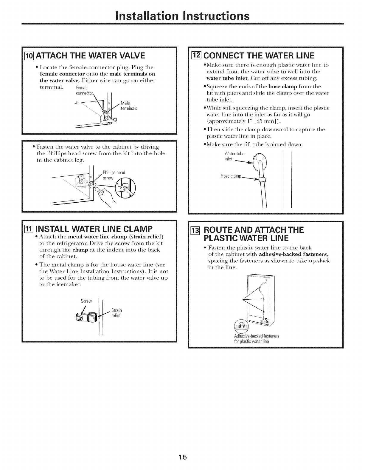
[TO-]ATTACH THE WATER VALVE
* Locate the female connector plug. Plug the
female connector onto the male terminals on
the water valve. Either wire can go on either
terminal. Female
0I/Male
_,_ terminals
* Fasten the water valve to the cabinet by driving
the Phillips head screw flom the kit into the hole
in the cabinet leg.
_ I Phiitipshead
o / screw
[i-27CONNECT THE WATER LINE
*Make sure there is enough plastic water line to
extend flom the water valve to well into the
water tube inlet. Cut off any excess robing.
*Squeeze the ends of the hose clamp flom the
ldt with pliers and slide the clamp over the wamr
robe inlet.
*While still squeezing the clamp, insert the plastic
water line into the inlet as flu as it will go
(approximately 1" [25 IIlIIl]).
*Then slide the clamp dowm,vard to capture the
plasdc water line in place.
*Make sure the fill robe is aimed down.
Water tube
inlet __
Hose clamp._
[_] INSTALL WATER LINE CLAMP
• Attach the metal water line clamp (strain relief)
to the refligerator. Drive the screw flom the kit
through the clamp at the indent into the back
of the cabinet.
* The metal clamp is for the house water line (see
the Water Line Installation Instructions). It is not
to be used for the robing flom the water valve up
to the icemaker.
ROUTE AND ATTACH THE
PLASTIC WATER LINE
Fasten the plastic water line to the back
of the cabinet with adhesive-backed fasteners,
spacing the f_steners as shown to take up slack
in the line.
Adhesive-backedfasteners
for plasticwater line
15

Installation instructions
ICEMAKER iNSTALLATiON iNSTRUCTiONS (CONT.)
WATER VALVE iNSTALLED
Refer to the Water i,ine Installation Instructions
for connection to the home water supply: After
water line installation is completed, set the
icemaker power switch to I (on).
The icemahing cycle will not begin until the icemaher
and freezer compartment reach operating temperature,
then icemahing will begin automatically.
[_ATTACH WARRANTY LABEL
A label is provided with this kit to record the date
of installation for warran V purposes. Apply it to the
back of the rehigerato_: The icemaker installation
inside the heezer is now complem.
16
Installation instructions
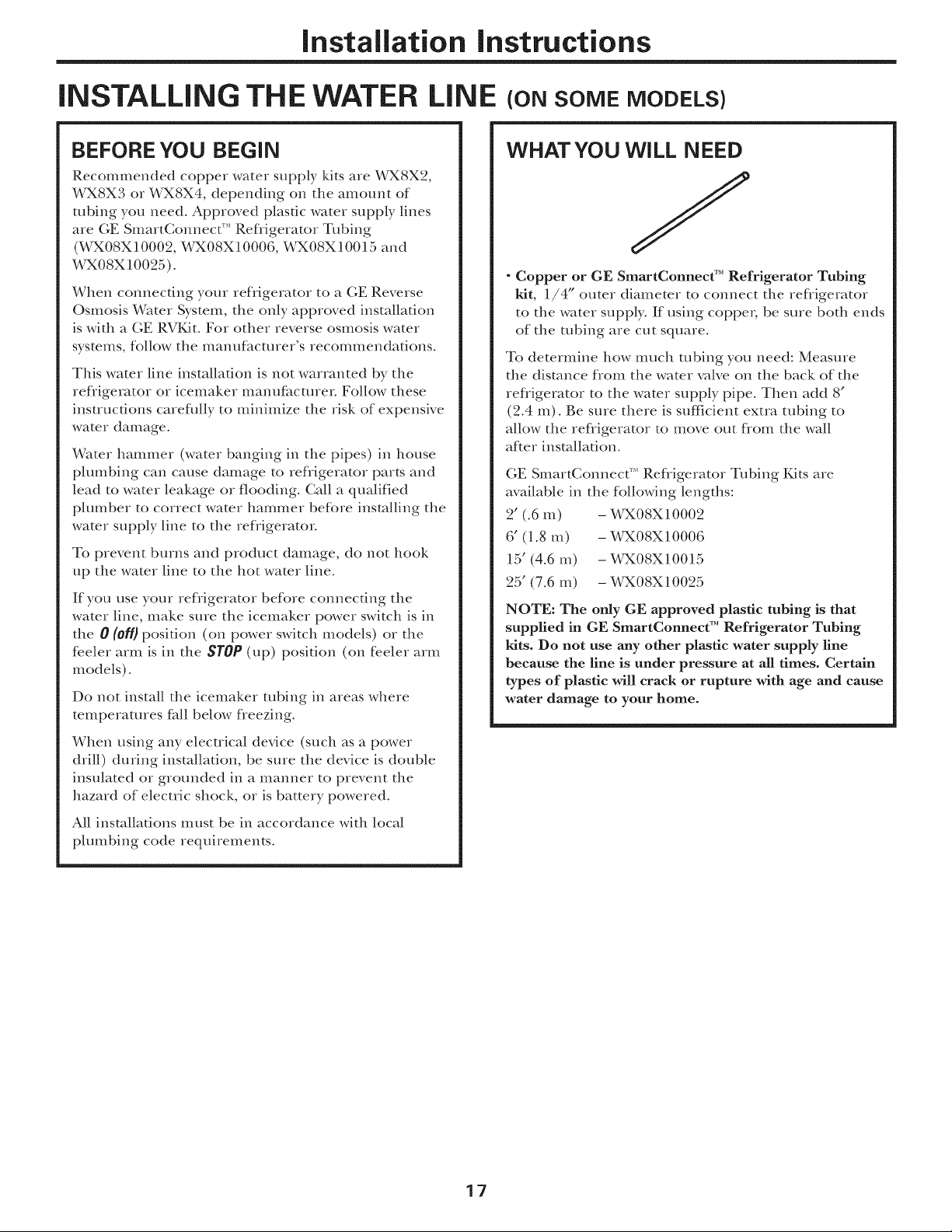
iNSTALLiNG THE WATER LiNE (ONSOMEMODELS)
BEFORE YOU BEGIN
Recommended copper water supply kits are WX8X2,
WX8X3 or WX8X4, depending on the amount of
ulbing you need. Approved plastic water supply lines
are GE SmartConnect F''Refiigerator Tubing
(WX08X10002, WX08X10006, WX08X10015 and
WX08X10025).
When connecting your refligerator to a GE Reverse
Oslnosis Water System, the only approved installation
is with a GE RVKIt. For other reverse osmosis water
systems, follow the manufhcmrer's recommendations.
This water line installation is not warranted by the
refiigerator or icemaker manufacturer. Follow these
instructions careflflly to minimize the risk of expensive
water damage.
Water hammer (water banging in the pipes) in house
plumbing can cause damage to refiigerator parts and
lead to water leakage or flooding. Call a qualified
plumber to correct water hammer before installing the
water supply line to the refiigerator.
To prevent burns and product damage, do not hook
up the water line to the hot water line.
If you use your refligerator before connecting the
water line, make sme the icemaker power switch is in
the 0 (off} position (on power switch models) or the
feeler arm is in the STOP (up) position (on feeler arIll
models).
Do not install the icemaker robing in areas where
temperatures f_dl below fieezing.
When using any electrical device (such as a power
drill) during installation, be sure the device is double
insulated or grounded in a manner to prevent the
hazard of electric shock, or is battery powered.
All installations Inust be in accordance with local
plumbing code requirements.
WHAT YOU WiLL NEED
J
" Copper or GE SmartConnect TM Refrigerator Tubing
kit, 1/4" outer diameter to connect the refligerator
to the water supply. If using coppm; be stue both ends
of the robing are CUt square.
To determine how much tubing you need: Measure
the distance fiom the water valve on the back of the
refiigerator to the water supply pipe. Then add 8"
(2.4 m). Be sure there is sufficient extra robing to
allow the refiigerator to move out flom the wall
after installation.
GE SmartConnect _"Refligerator Tubing Kits are
available in the following lengths:
2' (.6 m) - %_X08X10002
6" (1.8 m) - %PX08X10006
15' (4.6 m) - %PX08X10015
25' (7.6 m) - %_X08X10025
NOTE: The only GE approved plastic tubing is that
supplied in GE SmartConnect TM Refrigerator Tubing
kits. Do not use any other plastic water supply line
because the line is under pressure at all times. Certain
types of plastic will crack or rupture with age and cause
water damage to your home.
17
Installation instructions
iNSTALLiNG THE WATER LiNE
WHAT YOU WiLL NEED (CONT.)
" A GE water supply Mt (containing tubing, shutoff
valve and fittings listed below) is available at extra
cost flom your dealer or flom Parts and Accessories,
800.626.2002.
" A cold water supply. The water pressme must be
between 20 and 120 p.s.i. (1.4-8.1 bar).
- Power drill.
- 1/2" or adjustable wrench.
- Straight and Phillips blade screwdriver.
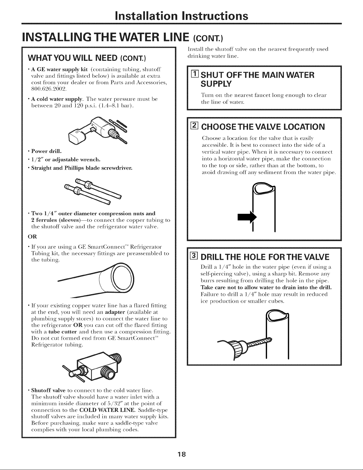
(CONT.)
Install the shutoff valve on the nearest f_equendy used
drinking water line.
m SHUT OFFTHE MAiN WATER
SUPPLY
Tmn on the nearest faucet long enough to clear
the line of water
[2-]CHOOSE THE VALVE LOCATION
Choose a location for the valve that is easily
accessible. It is best to connect into the side of a
vertical water pipe. When it is necessary to connect
into a horizontal water pipe, make the connection
to the top or side, rather than at the bottom, to
avoid drawing off any sediment flom the water pipe.
" Two 1/4" outer diameter compression nuts and
2 ferrules (sleeves)--to connect the copper robing to
the shutoff valve and the refligerator water valve.
OR
" If you are using a GE SmartConnect '_'Refiigerator
Tubing kit, the necessary fittings are preassembled to
the tubing.
" If your exisdng copper water line has a flared fitting
at the end, you will need an adapter (available at
plumbing supply stores) to connect the water line to
the refligerator OR you can cut off the flared fitting
with a tube cutter and then use a compression fitdng.
Do not cut formed end flom GE SmartConnect _''
Refligerator robing.
[-3-]DRILLTHE HOLE FOR THE VALVE
Drill a 1/4" hole in the water pipe (even if using a
self'piercing valve), using a sharp bit. Remove any
burrs resulting fiom drilling the hole in the pipe.
Take care not to allow water to drain into the drill.
Faihue to drill a 1,/4" hole may result in reduced
ice production or smaller cubes.
- Shutoff valve to connect to the cold water line.
The shutoff valve should have a water inlet with a
minimum inside diameter of 5/32" at the point of
connection to the COLD WATER LINE. Saddle-type
shutoff valves are included in many water supply kits.
Before purchasing, make sure a saddle-type valve
complies with your local phunbing codes.
18

Installation instructions
[] FASTEN THE SHUTOFF VALVE
Fasten the shutoff valve to the cold water pipe with
the pipe clamp.
PipeClamp_
Saddle-Type_/' l
ShutoffValve
NOTE: Commonwealth of Massachusetts Plumbing
Codes 248CMR shall be adhered to. Saddle valves
are illegal and use is not permitted in Massachusetts.
Consult with your licensed plumber.
VerticalCold
WaterPipe
_] TIGHTEN THE PIPE CLAMP
Tighten the clamp screws until the sealing washer
begins to swell.
NOTE: Do not overtighten or you may crush the
tubing.
PipeClamp--
Clamp
Washer
CONNECTTHE TUBING
TO THE VALVE
Place the compression nut and ferrule (sleeve)
for copper tubing onto the end of the tubing and
connect it to the shutoff valve.
Make sure the tubing is flflly inserted into the valve.
Tighten the compression nut securely.
For plastic tubing flom a GE SmartConnect _'*
Ref_igerator Tubing kit, insert the molded end
of the robing into the shutoff valve and tighten
compression nut until it is hand-fight; then tighten
one additional mrn with a wrench. Overflghtening
may cause leaks.
r-----Compression
Saddle-Type_ J_
ShutoffValve _,
PackingNut_
OutletValve.-/
NOTE: Commonwealth of Massachusetts Plumbing
Codes 248CMR shall be adhered to. Saddle valves
are illegal and use is not permitted in Massachusetts.
Constflt with your licensed plumber.
Nut
|SmartConnect _
[] ROUTETHETUBING
Route the robing between the cold water line and
the refligerator.
Route the robing through a hole drilled in the wall
or floor (behind the refrigerator or adjacent base
cabinet) as close to the wall as possible.
NOTE: Be sure there is sufficient extra tubing
to allow the refligerator to move out flom the wall
af*er installation.
FLUSH OUTTHETUBING
Turn the main water supply on and flush out the
robing until the water is clear
Shut the water off at the water valve after about
one quart (1 liter) of water has been flushed
through the robing.
19

Installation instructions
iNSTALLING THE WATER LINE (CONT.)
N-ICONNECTTHE TUBING TO THE
REFRIGERATOR
NOTES:
Before making the connection to the refligeratcm
be sure the refligerator power cord is not
plugged into the wall outlet.
We recommend installing a water filter if your
water supply has sand or particles that coukt clog
the screen of the refligerator's water valve° Install
it in the water line near the ref?igemtor. If using
GE SmartConnect r'' Refligerator Tubing kit, you
will need an additional robe (WX08X10002) to
connect the filter. Do not cut plastic tube to
install filter.
Remove the screws holding the right side of the
access cover Fold back the cover.
Remove the plastic flexible cap
flom the water valve
(refligerator connection).
Place the compression nut and
ferrule (sleeve) onto the end of
the tubing as shown. On (;E
SmartConnect'" Refligerator
Tubing kit, the nuts are aheady
assembled to the tubing.
Insert the end of the tubing into the water valve
connection as flu as possible. While holding the
tubing, tighten the fitting.
©
NI CONNECT THE TUBING TO THE
REFRIGERATOR (CONT.)
One of the illustrations below will look like the
connection on your refrigerator.
1/4"Tubing
3ressionNut
Ferrule(sleeve)
- Refrigerator
Tubing
Connection
[1-07TURN THE WATER ON ATTHE
SHUTOFF VALVE
Tighten any connections that leak.
For plastic robing flom a GE SmartConnect'"
Refligerator Tubing kit, insert the molded end
of the robing into the water valve connection and
tighten compression nut until it is hand-tight;
then tighten one additional turn with a wrench.
Overtightening may cause leaks.
Fasten the robing into the clamp provided to hokt
it in a vertical position. You may need to P_T open
the clamp.
Reatmch the access cover.
2O

Installation instructions
[] PLUG iN THE REFRIGERATOR
Arrange the coil of tubing so that it does not vibrate
against the back of the refrigerator or against the
wall. Push the refligerator back to the wall.
Makesureproper
groundexists
beforeuse.
IMPORTANT: PLEASE READ CAREFULLY
FOR PERSONAL SAFETY, THIS APPLIANCE
MUST BE PROPERLY GROUNDED.
Tile power cord of this appliance is equipped
with a 3-prong (grounding) plug that mates with
a standard 3-prong (grounding) wall receptacle
to minimize the risk of electric shock hazard f_om
this appliance. The customer should have the
wall receptacle and circuit checked by a qualified
electrician to make sure the receptacle is properly
grounded.
Where a standard two-prong wall receptacle is
encountered, it is the personal responsibility and
obligation of the customer to have it replaced with
a properly grounded 3-prong wall receptacle.
DO NOT, UNDER ANY CIRCUMSTANCES, CUT
OR REMOVE THE THIRD (GROUND) PRONG
FROM THE POWER CORD.
STARTTHE ICEMAKER
On power switch models, set the icemaker power
switch to the I (on}position. Oil feeler arm models,
move the feeler arm to the ON (down) position. The
icemaker will not begin to operate until it reaches
its operating temperauue of 15°F (-9°C) or below.
It will then begin operation automatically.
Powerswitch model
/7
//
........_ FeelerArminthe
...... STOP(up)position
FeelerArm in
the ON(down)position
Feelerarmmodel
NOTE: In lower water pressure conditions, the
water valve may Qun on tip to 3 times to deliver
enough water to the icemal<er.
REVERSING THE DOOR SWING
IMPORTANT NOTES
When reversing the door swing:
* Read the instructions all the way through before
starting.
* Handle parts carefldly to avoid scratching paint.
* Set screws down by their related parts to avoid using
them in the wrong places.
* Provide a non-scratching work surface for
the doors.
IMPORTANT: Once you begin, do not move the
cabinet until door-swing reversal is completed.
These instructions are for changing the binges flom
the right side to the lef_ side--if you ever want to change
the binges back to the right side, fbllow these same
instructions and reverse all references to lef* and right.
Unplug the refrigerator from its electrical outlet.
Empty all door shelves, including the dairy
compartment.
21
TOOLS YOU WILL NEED
5/16" socketandratchet
Phillipsscrewdriver
Maskingtape
Puttyknifeor
thin-bladescrewdriver
Installation instructions
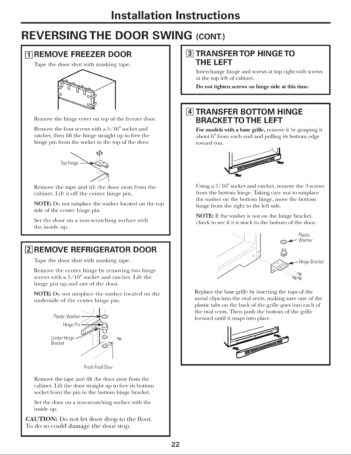
REVERSING THE DOOR SWING (CONT.)
TRANSFER TOP HINGE TO
[_ REMOVE FREEZER DOOR
Tape the door shut with masking tape.
Remove the binge cover on top of the fleezer doom
Remove the four screws with a 5/16" socket and
ratchet, then lift the binge straight up to flee the
binge pin flom the socket in the top of the door
TopHinge
%
THE LEFT
Interchange binge and screws at top right with screws
at the top left of cabinet.
Do not tighten screws on hinge side at this time.
[-4]TRANSFER BOTTOM HINGE
BRACKET TO THE LEFT
For models with a base grille, reIIlove it by grasping it
about 6" flom each end and pulling its bottom edge
toward you.
Remove the tape and tilt the door away flom the
cabinet, i,iR it off the center binge pin.
NOTE: Do not misplace the washer located on the top
side of the center binge pin.
Set the door on a non-scratching smf_tce with
the inside up.
REMOVE REFRIGERATOR DOOR
Tape the door shut with masking tape.
Remove the center binge by removing two binge
screws with a 5/16" socket and ratchet. Elf1 the
binge pin up and out of the door
NOTE: Do not misplace the washer located on the
underside of the center binge pin.
Plastic
'""--- I
Hinc
Using a 5/16" socket and ratchet, reiD.ore die 3 screws
flom the bottom binge. Taking care not to misplace
the washer on the bottom binge, move the bottom
binge flom the Hgbt to the left side.
NOTE: ff the washer is not on the binge bracket,
check to see if it is stuck to the bottom of the doo_:
Plastic
i
©_--_ Washer
Bracket
Replace die base grille by inserting die tops of the
metal clips into the ova/vents, maMng sure one of the
plasdc tabs on the back of the grille goes into each of
the ova/vents. Then push the bottom of the gnlle
fbrward until it snaps into place.
/
FreshFoodDoor
Remove the rope and flit the door away flom the
cabinet. Lift the door straight up to flee its bottom
socket flom the pin in the bottom binge bracket.
Set the door on a non-scratching smf_ce with the
inside up.
CAUTION: Do not let door drop to the floor.
To do so could damage the door stop.
22
Installation instructions
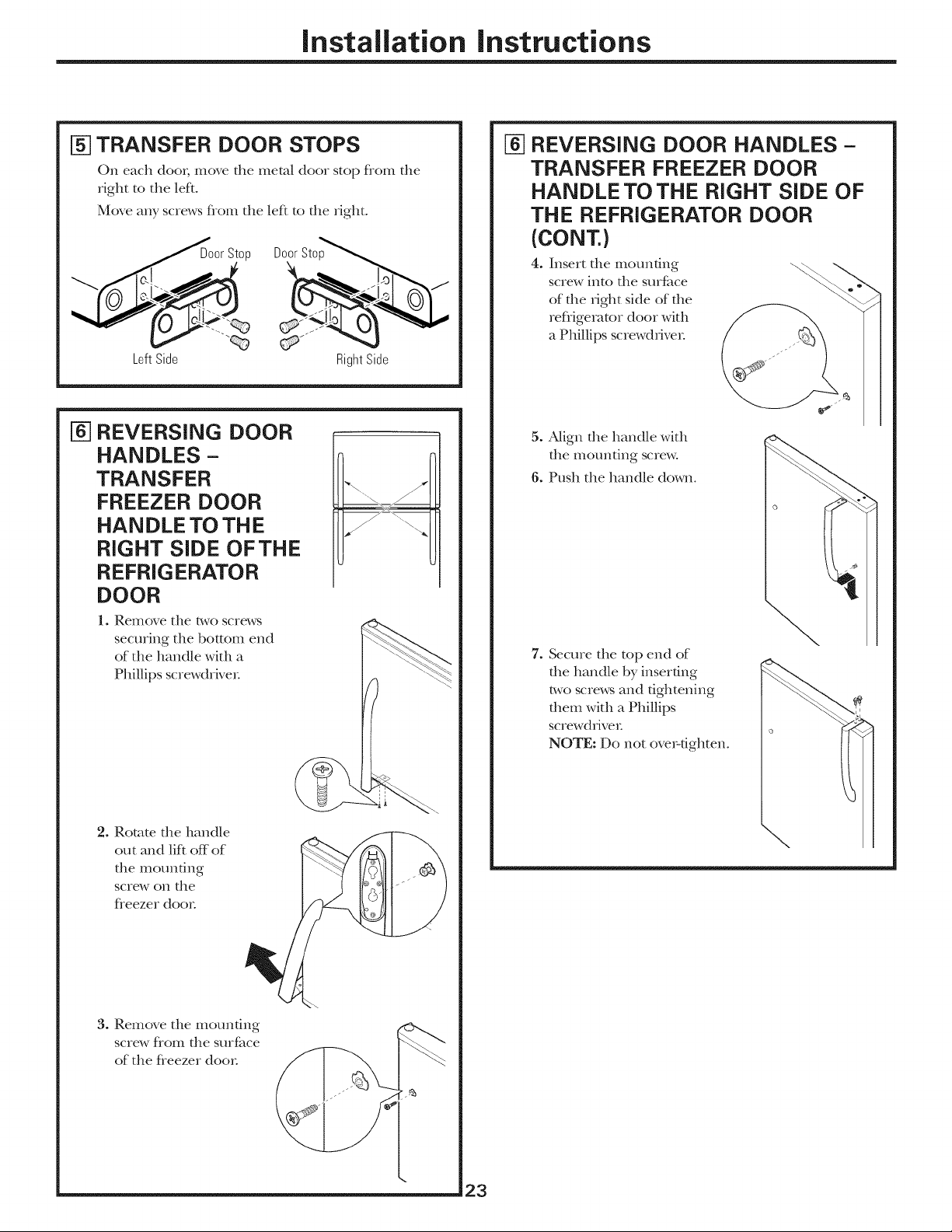
N1TRANSFER DOOR STOPS
On each do()/; move the metal door stop fiom the
right to the lefL
Move any screws fiom the leR to the _ight.
Door Stop Door Stop
LeftSide RightSide
[] REVERSING DOOR
HANDLES -
TRANSFER
FREEZER DOOR
HANDLE TO THE
RIGHT SIDE OF THE
REFRIGERATOR
DOOR
1. Remove the two screws
securing the bottom end
of the handle with a
Phillips screwdriver:
[] REVERSING DOOR HANDLES-
TRANSFER FREEZER DOOR
HANDLE TO THE RIGHT SiDE OF
THE REFRIGERATOR DOOR
(CONT.)
4. Insert file mounting
screw into the surface
of the IJght side of the
refiigemtor door with
a Phillips screwd_Jve,:
5. Align the handle with
the mounting screw°
6. Push the handle down°
7. Secure the top end of
die handle by inserting
two screws and tightening
them with a Phillips
screwdriver:
NOTE: Do not over-tighten.
2. Rotate file handle
out and lif* off of
file mounting
screw on the
fieezer do(n:
3. Remove the mounting
screw flom the surface
of the fieezer do(n:
\
23

Installation instructions
REVERSING THE DOOR SWING
_-] REVERSING DOOR HANDLES -
TRANSFER REFRIGERATOR
DOOR HANDLE TO THE RIGHT
SiDE OFTHE FREEZER DOOR
1. Remove the t_,voscrews
securing the top end of
file handle widl a Phillips
scre_,vdrive_:
2. Rotate die
handle out
and lift off of
the mounting
screw on file
reflJgerator
dooi:
(CONT.)
REVERSING DOOR HANDLES-
[]
TRANSFER REFRIGERATOR
DOOR HANDLE TO THE RIGHT
SiDE OFTHE FREEZER DOOR
(CONT.)
4. Insert file mounung screw
into the surfitce of the right
side of the fleezer door
with a Phillips screwdriver:
5. Align the handle with
the mounting screw°
6. Rotate the handle°
3. Remove the mounting
screw flom the surfime
of the reflJgemtor
dooi:
7. Secme the bottom end
of the handle by inserung
two screws and tightening
them with a Phillips
screwdriver
NOTE: Do not ore>tighten.
24

Installation instructions
NI REHANG THE REFRIGERATOR
DOOR
Lower the refligerator door onto the bottom
hinge pin°
Plastic
Screw die b,,voscrews into die center hinge location
on die left side with a 5/16" socket and ratchet.
Smdghten file door and place the center hinge pin
into the opening on top of file door Remember to
include tlle washer
Move the door into place, so you can align tlle center
hinge bracket over tlle center hinge holes on die left
side. Insert and tighten the two screws with a 5/16"
socket and ratchet.
NOTE: Ensure die washer is in place on top of die
hinge pin.
PlasticWasher_b
CenterHinge
Bracket
Hinge
I ..............
RefrigeratorDoor
[TO-]ADJUSTTHE DOORS
(IF NEEDED)
If the freezer door is too high:
Remove the hinge
cover on top of the
fleezer door and
loosen the four
screws with a 5/16"
socket and ratchet.
Replace tlle hinge
covei:
Loosenscrews. 5/16" __
%
I
If both doors are too high:
1. Remove
the hinge Loosenscrews.
cover on
top of tlle
door and
loosen the
f}om screws
with a
5/16"
fleezer _
socket and
ratchet.
.
Loosen die two center hinge screws wkh a 5/16"
socket and ratchet.
3. Slide tlle center hinge to die left to lower
tlle doors.
4. Fully tighten all screws and replace top hinge cove,:
%
5/16
_ oosen
5/16"
screwsand
slideleft to
lowerdoors.
[] REHANG THE FREEZER DOOR
Lower die fleezer door onto die center hinge pin.
Be sure die washer is in place.
igePin
Washer
iJfl die top hinge so die pin fits into die door socket.
Support the door on the handle side and make sme
the door is straight and the gap bet_,veen the doo_s is
even across the flont. While holding the door in
place, dghmn the top hinge screws.
25
If both doors are too low:
1. Remove die
hinge cover
on top of
the fleezer
door and
loosen the t
fbur screws
with a 5/16"
socket and t
ratchet.
2. Loosen the
bwo cenmr
hinge screws
wkh a a/16 socket and ratchet.
3.
Slide tlle center hinge to die fight to raise
the doors.
4. Fully dghten all screws and replace
top hinge cove_:
NOTE: Save the door spacer
Doo_ may settle with use. DoorSpacer
Loosenscrews. 5/16'_'
<&Loosen
5/16"
screwsand
sliderightto
raisedoors.
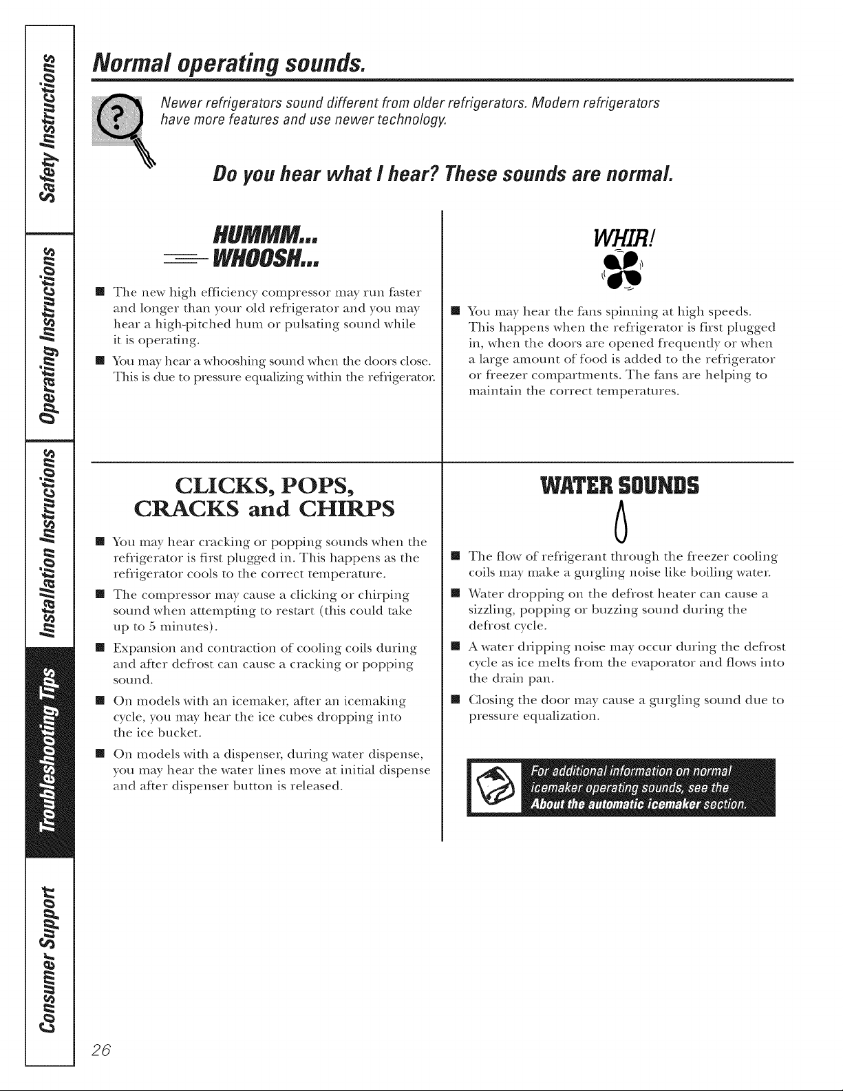
Normal operatingsounds.
Newer refrigerators sound different from older refrigerators, Modern refrigerators
have more features and use newer technology,
Do you hear what / hear? These sounds are normal
HUMMM.,
-- WHOOSH...
[] The new high efficiency compressor may run faster
and longer than yore old refligerator and you may
hear a high-pitched hum or pulsating sound while
it is operating.
[] You m W hear a whooshing sound when the doors close.
This is due to pressure equalizing within the refligerator
[] You may hear the rims spinning at high speeds.
This happens when the refrigerator is first plugged
in, when the doors are opened f}equently or when
a large amount of food is added to the ref_igerator
or freezer compamnents. The rims are helping to
maintain the correct temperatures.
CLICKS, POPS,
CRACKS and CHIRPS
[] You may hear cracking or popping sounds when the
refiigerator is first plugged in. This happens as the
refligerator cools to the correct temperature.
[] The compressor may cause a clicMng or chirping
sound when attempting to restart (this could rake
up to 5 minutes).
[] Expansion and contraction of cooling coils during
and after defrost can cause a cracking or popping
so/xxld.
[]
On models with an icemakm, after an icemaking
cycle, you may hear the ice cubes dropping into
the ice bucket.
[]
On models with a dispenser, during water dispense,
you may hear the water lines move at initial dispense
and af*er dispenser button is released.
WATERSOUNDS
6
[] The flow of refligeram fllrough file fleezer cooling
coils may make a gurgling noise like boiling water.
[] Water dropping on die deflost heater can cause a
sizzling, popping or buzzing sound during die
deflost cycle.
[] A water dripping noise may occur dming the deflost
cycle as ice melts flom the evaporator and flows into
the drain pan.
[] Closing the door may cause a gurgling sound due to
pressure equalization.
26

Beforeyouca//for service...
GEPpp/iances.com
Troubleshooting tips
Save time and money! Review the charts on the following
pages first and you may not need to call for service,
Possible Causes What ToDo
Freezer doorpops open This is normal if, after = This h_dk:ates that there is a good sea| on the fleezer
when refrigerator door popping open, the freezer docn: If the fleezer door does not automatically close after
is closed door closed on its own. popping open, the rollers need adjusting. See Rollers and
Leveling Legs.
Boor does not close Leveling legs need adjusting. • See Rollers and Leveling Legs.
by itself
Refrigerator does Refrigerator in defrost cycle. • Wak about 40 minutes for deft ost cycle to end.
not operate Refrigerator control in • Move the refligerator and fleezer control to a
1(Off)position. temperature setting.
Refrigerator is unplugged. • Push the plug completely into the Buffet.
The fuse is blown/ekcnit • Replace disc or reset the breaker:
breaker is tripped.
Vibration or rattling Refrigerator is not resting • Adjust leveling legs (See Rollers and Leveling Legs).
(slight vibration on all four rollers.
is normafl
Motor operates for Normal when refrigerator = Wait 24 hours for the refligerator to completely
long periods or cycles is first plugged in. coo/down°
on and off frequently
(Modern refrigerators Often occurs when large • This is nom_al.
with more storage
space and a larger placed in refrigerator.
freezer require more Door left open. + Check to see if package is hokting door open°
operating time. They
start and stop often Hot weather or frequent • This is nomlal.
tomaintain even door openings.
temperatures.) Temperature controls set + See About the controls.
Refrigerator orfreezer Temperature control not set • See About the controls.
compartment too warm cold enough.
Froster ice cn/stals Door left open. +Check to see if package is holdh_g door open.
on frozenfood
(frost within package
is normal) door openings.
amounts of food are
at the coldest setting.
Warm weather or frequent • Set the temperature control one step coldeL
door openings. See About the controls.
Door left open. • Check to see if package is hoMing door open.
Freezer door popped open. • See the problem Freezer door pops open when
refrigerator door is closed.
Too frequent or too long
Food blocking freezer air vents. • Move items away flom the back wall of the fleeze_:
Frequent"buzzing"
sound
Smallorhollow cubes
Icemaker power switch is in
the I (on) position, but the
water supply to the refrigerator
has not been connected.
Water f'flter clogged. *Replace filter cartridge with new cartridge or with plug.
*Set the power switch to the 0 (off) position. Keeping it
in the I(on)position will damage the water valve.
27
Beforeyoucall forservice..,
Troubleshooting tips
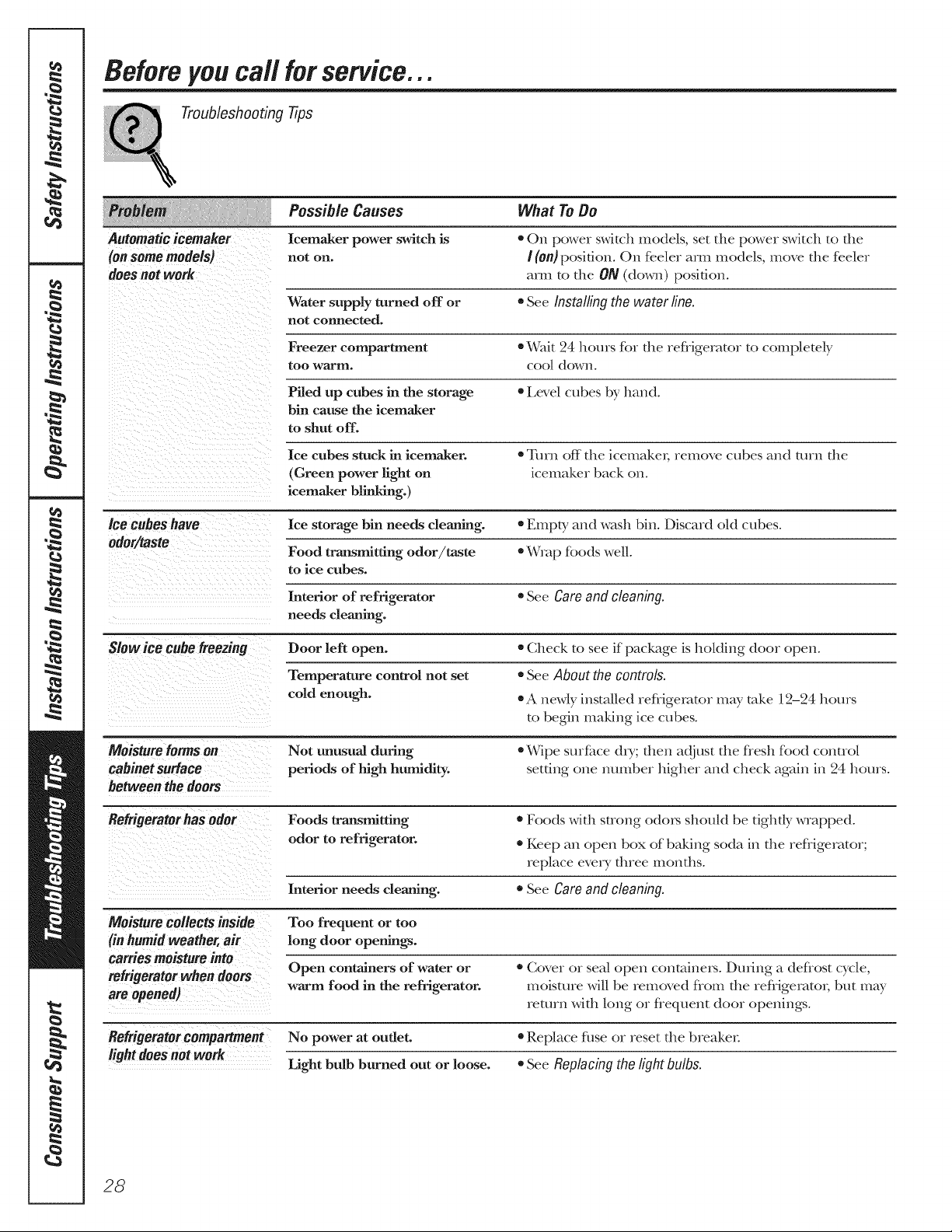
Possible Causes What ToDo
Automatic icemaker Icemaker power switch is = On power swkch models, set the power switch to the
(on some models) not on. I (on) position. On feeler am1 models, move the feeler
does not work am_ to the ON ((to\,_q_) position.
Water supply turned off or • See Installing the water line.
not connected.
Freezer compartment • Wait 24 hours fin the refligerator to completely
too warnl, coo[ down°
Piled up cubes in the storage • Level cubes by hand.
bin cause the icemaker
to shut off.
Ice cubes stuck in icemaker. • Turn off the icemake_; remove cubes and turn the
(Green power fight on icemaker back on.
icemaker blh_dng.)
Ice cubes have Ice storage bin needs cleaning. • Empty and wash bin. Dhcard oM cubes.
odor/taste
Food transmitting odor/taste = Wrap fbods well.
to ice cubes.
Interior of refrigerator • See Care and cleaning.
needs cleaning.
Slow ice cube freezing Door left open. • Check to see if package is hoMing door open.
Temperature control not set • See About the controls.
cold enough. • A newly insm|led refligerator may tnke l2-24 hours
to begin making ice cubes.
Moisture forms on Not unusual{ during • Wipe surfhce dry; then adjust the flesh fbod control
cabinet surface periods of high humidity, setting one nunlber higher and check again in 24 hours.
between the doors
Refrigerator has odor Foods transmJtting • Foods with strong o(kns should be tightly wrapped.
odor to refrigerator. • Keep an open box of baking soda in the refligerator;
replace every t]uee months.
Interior needs cleaning. • See Care and cleaning.
Moisture collects inside Too frequent or too
(in humid weather, air long door openings.
carries moisture into
refrigerator when doors Open containers of water or = Cover or seal open contnine_. DuAng a deflost cycle,
are opened) return with long or flequent door openings.
Refrigerator compartment No power at outlet. • Replace fl_se or reset the breaken
light doesnot work Light bulb burned out or loose. • See Replacing the light bulbs.
warm food in the refrigerator, moisture will be removed flom the refligerato_, but may
28
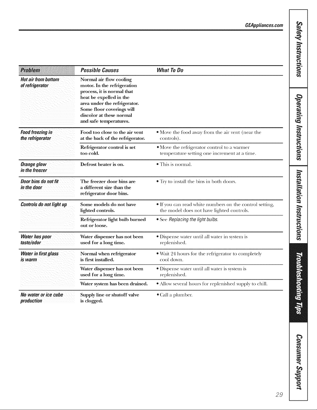
Possible Causes What ToDo
GEPpp/iance&com
Hotair frombottom
ofrefrigerator
Food freezing in Food too close to the air vent • Move the fbod mvay flora the ah vent (near the
the refrigerator at the back of the refrigerator, controls).
in the freezer
Boor bins do not fit The freezer door bins are • Try to inst_dl the |)ins in both doox_.
in the door a different size than the
Controlsdo aotlightup Some models do not have •l[f yo/_ can read whke m_tnbex_ on the control setting,
Normal air flow coofing
motor. In the refrigeration
process, it is normal that
heat be expelled in the
area under the refrigerator.
Some floor coverings will
discolor at these normal
and safe temperatures.
Refrigerator control is set * Move the refiigerator control to a warmer
too cold. temperature setting one increment at a time.
Defrost heater is on. * This is n(nmal.
refrigerator door bins.
lighted controls, the model does not have lighted controls.
Refrigerator light bulb burned • See Replacing the light bulbs.
out or loose.
Water has poor Water dispenser has not been * Dispense water until all water in system is
taste/odor used for a long time. replenished.
Water in firstglass Normal when refrigerator • Wak 24 hours for the refligemtor to completely
iS warm is first installed, coo/down.
Water dispenser has not been • Dispense water undl all water is system is
used for a long time. replenished.
Water system has been drained. • Allow several hours hn replenished supply to chill°
No water orice cube Supply line or shutoff valve • (]all a plumbe_:
production is clogged.
29
 Loading...