


 Loading...
| <![if ! IE]> <![endif]>Disposall® |
<![if ! IE]> <![endif]>Food Waste Disposer |
GEAppliances.com
Safety Instructions
Connecting Electricity . . . . . 2, 3
Safety Precautions . . . . . . . . . . 2
Installation Instructions
Attaching the
Discharge Elbow . . . . . . . . . . . . 6 Components and Installation
of Sink Flange . . . . . . . . . . . . . 5 Connecting Disposer
to Sink Flange . . . . . . . . . . . . . .7 Dimensions/Typical
Installations . . . . . . . . . . . . . . . .8 Dishwasher Connection . . . . . . 6
Operating Instructions
Batch Feed Models . . . . . . . . . .9
Care and Maintenance . . . . . .10
Continuous Feed Models . . . . .9
Troubleshooting Tips
Before You Call for Service . . . .11
Consumer Support
Warranty . . . . . . . . . . . . . . . . 12
Write the model and serial numbers for your disposall here:
Model # ______________________
Serial # ______________________
You can find them on a label on the bottom of the disposer.
Owner’s Manual
& Installation
Instructions
Model Line Series
GFC320
GFC520
GFC530
GFC720
GFC1020
GFB760
165D4700P250 49-5924 04-02 JR
IMPORTANT SAFETY INSTRUCTIONS.
READ ALL INSTRUCTIONS BEFORE USING.
INSTRUCTIONS PERTAINING TO A RISK OF FIRE, ELECTRIC SHOCK OR INJURY TO PERSONS
 WARNING!
When using electrical appliances, basic safety precautions should be followed, including the following:
SAFETY PRECAUTIONS
■Use this appliance only for its intended purpose as described in this Owner’s Manual.
■Read all the instructions before using the appliance.
■To reduce the risk of injury, close supervision is required when an appliance is used near children.
■To reduce the risk of injury by materials that may be expelled by a waste disposer, do not put the following into a disposer:
a)Clam or oyster shells.
b)Caustic drain cleaners or similar products.
c)Glass, china or plastic.
■Do not put fingers or hands into a waste disposer.
■Turn the power switch (normally a wall switch) to the off position before attempting to clear a jam or remove an object from the disposer.
■When attempting to loosen a jam in a waste disposer, use a long wooden object such as a wooden spoon or the wooden handle of a broom or mop.
■When attempting to remove objects from a waste disposer, only use long-handled, non-magnetic tools or utensils, since the disposer may be actuated magnetically.
d)Large whole bones.
e)Metal, such as bottle caps, tin cans, utensils or aluminum foil.
f)Hot grease or other hot liquids.
g)Whole corn husks.
■When not operating a disposer, leave the drain stopper in place to reduce the risk of objects falling into the disposer.
■For proper grounding instructions, see the ELECTRICAL CONNECTION portion of this manual.
 WARNING!
HOW TO CONNECT ELECTRICITY
If you are not familiar with electrical power and procedures, call a qualified electrician.
DANGER: Improper connection of the equipmentgrounding conductor can result in a risk of electric shock. Check with a qualified electrician or serviceman if you are in doubt as to whether the appliance is properly grounded. Do not modify the plug provided with the appliance if it will not fit the outlet; have a proper outlet installed by a qualified electrician.
For Models Equipped with a Grounded Cord:
GROUNDING INSTRUCTIONS: This appliance must be grounded. In the event of a malfunction or breakdown, grounding provides a path of least resistance for electric current to reduce the risk of electric shock. This appliance is equipped with a cord having an equipment-grounding conductor and a grounding plug. The plug must be plugged into an appropriate outlet that is properly installed and grounded in accordance with all local codes and ordinances. Most houses have electrical outlets under the sink that are half-hot. This means one outlet is controlled by the wall switch, while the other is always hot. The batch-feed or “TC” model connects to the hot side, while the continuous feed model connects to the switch side.
2
GEAppliances.com
 WARNING!
HOW TO CONNECT ELECTRICITY (cont.)
If you are not familiar with electrical power and procedures, call a qualified electrician.
The power cord and/or connections must comply with the National Electrical Code, Section 422 and/or local codes and ordinances.
For Models Not Equipped with a Cord:
If your disposer does not come equipped with a cord, you can connect it in two ways:
1.Attach a power cord, minimum 18″ in length and not to exceed 36″ in length. GE Kit #PM3X115 provides the parts needed to make this connection.
or
2.Wire the disposer directly into the house current.
GE recommends that a qualified electrician make this connection.
To Attach a Power Cord:
GROUNDING INSTRUCTIONS: This appliance must be grounded. In the event of malfunction or breakdown, grounding provides a path of least resistance for electric current to reduce the risk of electric shock. The power cord (to be installed) must have an equipment-grounding conductor and a grounding plug. The plug must be plugged into an appropriate outlet that is properly installed and grounded in accordance with all local codes and ordinances.
In the absence of local codes and/or ordinances, the outlet must comply with NEC requirements.
DANGER: Improper connection of the equipmentgrounding conductor can result in a risk of electric shock. Check with a qualified electrician or serviceman if you are in doubt as to whether the appliance is properly grounded.
NOTE: Disconnect electric power to disposer circuit before installation. Turn the circuit breaker to the OFF position or remove the fuse.
A.Connect the disposer to 110–120 Volt, 60 Hz AC current only.
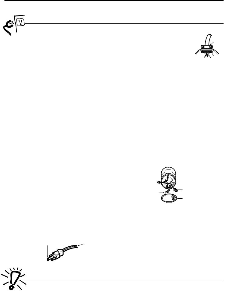
B.If a plug-in cord is used, use a three-prong plug. Ground wire should be attached to the ground screw in the bottom of the disposer (end bell).
Trace lead connected to this |
Ribbed |
blade and attach that lead |
|
to white wire on disposer. |
Side |
NOTE: When viewing face of electrical plug with grounding pin at top, the larger left blade is connected to the identified wire.
C. Use a cable clamp strain relief |
|
connector where power cord |
Strain |
enters the disposer. |
Relief |
To Wire Your Disposer Directly into
the House Current:
Nut
GE recommends that a qualified electrician make this connection.
GROUNDING INSTRUCTIONS: This appliance must be connected to a grounded, metal, permanent wiring system; or an equipment-grounding conductor must be run with the circuit conductors and connected to the equipment-grounding terminal or lead on the appliance.
DANGER: Improper connection of the equipmentgrounding conductor can result in a risk of electric shock. Check with a qualified electrician or serviceman if you are in doubt as to whether the appliance is properly grounded.
A.If you use BX cable:
1.Install the cable connector in the hole.
2.Connect white wire to white lead of disposer.
3.Connect black wire.
4.Connect bare ground wire.
If BX cable is not used, provide a separate ground wire to the nearest grounded connection, using the screw in the end bell for the ground wire.

 Red Reset Button

 Ground Screw
To House Current |
Wire Nuts |
|
Remove |
||
or Power Cord |
||
|
Cover Plate |
Bottom of the Disposer (end bell)
B.If your power supply does not include a ground wire, you must provide one unless metal cable is used. Attach a copper wire securely to disposer ground screw and attach other end of wire to the nearest grounded connection. Use only UL approved ground clamp. If plastic pipe is used in your home, a qualified electrician should install a proper ground. Most houses have electrical outlets under the sink that are halfhot. This means one outlet is controlled by the wall switch, while the other is always hot. The batch-feed or “TC” model connects to the hot side, while the continuous feed model connects to the switch side.
READ AND FOLLOW THIS SAFETY INFORMATION CAREFULLY.
SAVE THESE INSTRUCTIONS |
3 |

Installation Disposer
Instructions
If you have questions, call 800.GE.CARES (800.432.2737) or Visit our Website at: GEAppliances.com
BEFORE YOU BEGIN
Read these instructions completely and carefully.
• IMPORTANT – Save these
instructions for local inspector’s use.
• IMPORTANT – Observe all
governing codes and ordinances.
• Note to Installer – Be sure to leave these instructions with the Consumer.
• Note to Consumer – Keep these instructions for future reference.
•Skill level – Installation of this appliance requires basic mechanical skills.
•Completion time – 1 hour
•Proper installation is the responsibility of the installer.
•Product failure due to improper installation is not covered under the Warranty.
PREPARATION
1.Disconnect electrical power supply to disposer.
2.Remove old disposer or sink flange assembly.
3.Inspect drain line. If it is heavily coated with hardened grease and accumulations, rout out with a plumber’s snake.
4.Remove old sealing materials and gasketing from sink opening, both top and bottom.
NOTE: Top and bottom of sink surfaces must be free of any materials to prevent leaks.
WHAT YOU WILL NEED
• Phillips and flat blade screwdrivers
• Channel lock pliers, slip joint |
• Hammer |
• Nut driver
ADDITIONAL MATERIALS YOU MAY NEED
•Steel punch or wooden dowel
•Petroleum jelly or liquid soap
•Hose clamp
•Dishwasher drain connector
•Adjustable pipe wrench
•Plumber’s putty (for cast sinks)
•Stepped rubber drain adapter
•Wire nuts
•Cable connector
•Flexible drain pipe
•Power cord kit (Part Number PM3X215GDS)
4

Installation Instructions
1 COMPONENTS AND INSTALLATION
COMPONENTS
|
*Stopper |
|
|
*Removable |
|
|
Splash Guard |
|
|
Sink Flange |
|
|
Rubber Sink |
|
|
Flange Gasket |
|
Sink Flange |
|
Sink |
|
|
|
Assembly |
Fiber Gasket |
|
|
||
|
Support Ring |
|
|
(Note Arrows |
|
|
Indicating Up) |
|
|
Mount Ring |
|
|
Tightening Ears |
|
|
Cushion Mount |
|
Groove |
Dishwasher |
|
|
Discharge Inlet |
|
|
Elbow Gasket |
|
Hopper |
|
|
Disposer |
|
Screws |
|
Elbow |
Discharge |
End Bell |
Flange |
|
|
Elbow |
|
(Electrical |
|
|
Rating Label |
|
|
Connections) |
|
|
|
in This Area |
|
*Not used with batch feed model
INSTALLATION OF SINK FLANGE
(Read completely before starting.)
Correctly Installed Sink Flange
Sink Flange |
Rubber Gasket |
|
Fiber Gasket |
Sink |
|
Support Ring |
||
Bottom Bead of |
||
Sink Flange |
||
Cushion Mount |
||
|
||
Open Area No Obstruction |
Mount Ring should be free |
|
|
to move up and down |
Groove 
 Cushion Mount
Bottom Bead
(shown for proper orientation)
NOTE: Pay close attention to the order of the sink flange parts, as they have been correctly assembled by the factory.
A.Disassemble the sink flange assembly from the disposer by turning the mount ring to the left (clockwise) and removing it.
B.Raise the mount ring toward the top of the sink flange. Remove the cushion mount and the mount ring. You may want to practice installing the cushion mount at this point before you are under the sink.
C.Unscrew the support ring from the sink flange and remove the fiber gasket. You are now left with the sink flange and the rubber gasket.
D.The rubber gasket is used instead of plumbers putty with stainless steel sinks.
E.If no putty is used, insert the sink flange through the rubber gasket into the sink opening. Do not turn the flange once it is seated.
F.If you use putty instead of the gasket, form a ring around the underside of the sink flange. Insert the flange into the sink opening, press down hard to squeeze out excess putty. From under the sink, trim off excess putty flush with the bottom edge of the sink opening. Use putty sparingly on cast iron sinks.
G. From underneath the sink, slip the fiber gasket onto the exposed sink flange. With
arrows pointing up, screw the support ring onto the sink flange and hand tighten until the sink flange will not move. At
this point you may want to insert the stopper in the sink and fill with water to check the sink flange seal and insure there are no leaks.
H.Place the mount ring over the sink flange and hold in place while installing the cushion mount (large side down). Make sure the groove on the inside of the cushion mount fits over the
lip on the sink flange, |
|
|
Cushion Mount Detail |
similar to putting the lid |
|
Top |
|
on a plastic container. |
Groove |
||
|
|
||
Run your fingers |
Bottom |
|
|
around the entire |
|
||
cushion mount with |
Bead |
|
|
|
|
|
|
slight pressure. Do not press too hard. When the cushion mount is properly seated, the mount ring can be pulled downward over the cushion mount and will be free to turn.
5
Installation Instructions
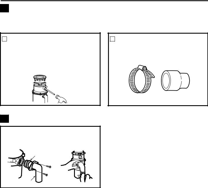
2 DISHWASHER CONNECTION (IF REQUIRED)
If you are connecting to a dishwasher, complete the following step. If a dishwasher is not to be connected, go on to “Attaching the Discharge Elbow” section.
1 KNOCK OUT PLUG
Using a blunt instrument (steel punch or wooden dowel), knock out entire plug. Do not use a screwdriver or sharp instrument. When knockout plug falls into disposer, you may remove it or simply grind it up when the disposer is used. This will not damage the disposer in any way, but may take some time to grind, over the course of several
uses.
 Knock out
  plug
plug
2 CONNECT HOSE
Connect the dishwasher hose using a hose clamp. If the hose size is different, you will need a stepped rubber adapter.
Hose Clamp |
Stepped Rubber Adapter |
3 ATTACHING THE DISCHARGE ELBOW
CONNECT DISCHARGE ELBOW
Connect the discharge elbow to the disposer.* Make sure all plumbing connections are tight.
Rubber
Gasket
*Some installations (see page 8 for examples) may require the use of a flexible drain pipe.
Discharge
Elbow
6
Installation Instructions
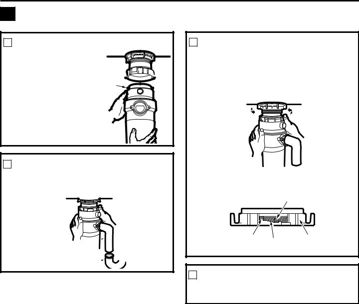
4 CONNECTING DISPOSER TO SINK FLANGE
1 ATTACH TO SINK FLANGE
Line up the disposer under the sink flange. Guide the hopper projections into the mount ring slots. Turn the mount ring about 1/4″ to the right so that the disposer is temporarily supported.
Mount
Ring Slot 

Hopper
Projection
2 LINE UP WITH OUTLET PIPE
Turn the mount ring and the disposer until the disposer discharge elbow lines up with the outlet pipe (see page 8).
Discharge 
Elbow
Outlet Pipe 
3 LOCK MOUNT RING
Turn the mount ring slowly to the right until it locks up tight. Hopper projections must be to the extreme left of the mounting slots. If the mount ring is hard to turn, you may add a small amount of petroleum jelly or liquid soap to the hopper projection. Run water and check for leaks.
Locking Detail
Hopper Projection in
“Supported” Position
|
|
|
|
|
|
|
Mount |
|
|
|
|
|
|
|
|
||
|
|
|
|
|
|
|
||
Hopper Projection |
|
|
|
|
||||
Mounting Slot |
||||||||
in “Locked” Position |
Ring |
|||||||
4 CHECK FOR LEAKS
Check the unit for leaks 24 hours after installation and first operation.
7
Installation Instructions
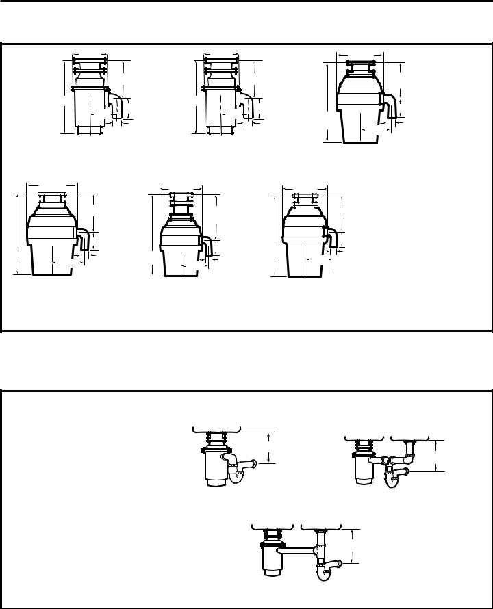
DIMENSIONS
5 3/16” |
5 3/16” |
73/4” |
63/16” |
63/16” |
615/16” |
1211/16” |
1211/16” |
|
|
|
|
53/8” |
41/2” |
|
53/8” |
41/2” |
|
|
|
|
4 1/2” |
|
|
|
|
|
|
|
137/16” |
|
|
|
11/2” |
||
|
|
|
|
|
11/2” |
|
|
11/2” |
|
|
|
||
|
|
|
|
|
|
|
|
|
|
|
|||
|
|
|
|
|
|
|
|
|
|
|
|
|
53/8” |
|
|
|
|
GFC320 |
|
|
GFC520 |
|
|
|
|
|
GFC530 |
|
|
|
|
GFC325 |
|
|
GFC525 |
|
|
|
|
|
|
|
|
|
|
|
|
|
|
|
|
|
|
|
GFC535 |
|
|
|
8 1/2” |
|
8 1/2” |
|
|
|
8 1/2” |
|
|
|
|
|
|
|
|
7 1/4” |
|
|
93/8” |
|
7 |
1 |
/4” |
||
|
|
|
|
|
|
|
|
|
|||||
|
|
|
|
4 1/2” |
|
|
4 1/2” |
|
|
4 1/2” |
|||
14 |
1 |
/2” |
|
11/2” |
165/8” |
|
161/16” |
5 9/16” |
|
1 |
1 |
/2” |
|
|
5 9/16” |
9 |
11/2” |
|
|
|
|||||||
|
|
|
|
|
5 |
|
/16” |
|
|
|
|
|
|
|
|
|
GFC720 |
|
GFB760 |
|
|
|
GFC1020 |
|
|
|
|
Batch Feed Operation
SOME TYPICAL INSTALLATIONS
Direct replacement for most makes & models.
*9″ for model GFC320, GFC520, GFC325 & GFC525.
SINGLE BOWL |
DOUBLE BOWL |
|
CENTER OUTLET** |
*Approx. |
*Approx.
*10″ for models GFC530, |
|
GFC535, GFC720 |
|
& GFC1020. |
|
*12″ for model GFB760. |
DOUBLE BOWL |
|
END OUTLET** |
NOTE: It is essential for the proper |
|
operation of the disposer that this |
*Approx. |
dimension be 9″–12″, depending upon the |
|
models listed above, to avoid standing water |
|
in disposer motor housing. |
|
**Flexible drain pipe may be necessary for this application.
8
Loading...