


GFDS260GF2WW
GE GFDS260GF2WW, GFDS260EF2WW, GFDR275GH1MC, GFDR275GH0MC, GFDR275EH1MC Owner’s Manual
...
0
GEAppliances.com
Safety Instructions ........... 2-4
Operating Instructions
Controls ........................... 4-8
Quick Start ........................... 9
Using the Dryer ...................... 9
Features ............................ 10
Care and Cleaning ............ 11
Installation Instructions
Before You Begin ............... 12- 14
Connecting the inlet Hoses ......... 15
Connecting a Gas Dryer ......... 16-19
Connecting an
Electric Dryer .................... 20-22
Exhausting the Dryer ............ 23-29
Final Setup .......................... 30
Reversing the Door Swing ....... 31-35
Stacking the Washer
and Dryer ....................... 36-38
GFDR485
GFDR480
GFDS5 75
GFDS5 70
GHDS565
GHDS560
GFDR275
GFDR270
GFD5265
GFD5260
GFD5255
GFDS250
S cheuses
Troubleshooting Tips....... 39-42
Consumer Support
Consumer Support ........ Back Cover
Warranty (Canada) ................. 44
Warranty (U.S.)..................... 43
/ i _
Write the model ond serial
numbers here:
Model #
Lo section frangaise commence _ la page 45
Secadoras
La secci6n en espafiol empieza en la p6gina 91
Printed inthe United States
Seriol #
They are on the label on the front
of the dryer behind the door.
49-90519-1
11-14GE
IMPORTANT SAFETY INFORMATION.
READ ALL INSTRUCTIONS BEFORE USING.
A Thisis the safety alert symbol. This symbol alerts to potential hazards that can kill or hurt and others. All
safety messages will follow the safety alert symbol and the word "DANGER","WARNING', or "CAUTION".These words
are defined as:
_ Indicates a hazardous situation which, if not avoided, will result in death or serious inJury.
Indicates a hazardous situation which, if not avoided, could result in death or serious injury.
Indicates a hazardous situation which, if not avoided, could result in minor or moderate inJury.
you you you
IMPORTANT SAFETYINSTRUCTIONS
To reduce the riskof fire, explosion,electric shock, or injury to persons when using your appliance, follow basic
precautions, including the following:
[] Readall instructionsbefore usingtheappliance.
[] DONOTdry articles that have been previously cleaned in,washed in, soaked in or spotted with gasoline, dry-cleaning
solvents, or other flammable or explosive substances, as they give off vapors that could ignite or explode.
[] DONOTallow children to play on or in this appliance. Close supervision of children is necessary when this appliance
is used near children. Before the appliance is removed from service or discarded, remove the door to the drying
compartment.
[] DONOTreach into the appliance if the drum is moving.
[] DONOTinstall or store this appliance where it will be exposed to the weather.
[] DONOTtamper with controls, repair or replace any part of this appliance or attempt any servicing unless specifically
recommended in the user maintenance instructions or in published user repair instructions that you understand and have
the skills to carry out.
[] DONOTuse fabric softeners or products to eliminate static unless recommended by the manufacturer of the fabric
softener or product.
[] DONOTuse heat to dry articles containing foam rubber or similarly textured rubber-like materials.
[] Clean lint screen before or after each load. DONOToperate the dryer without the lint filter in place.
[] Donot store combustible materials, gasoline or other flammable liquids near the dryer. Keep area around the exhaust opening
and adjacent surrounding areas free from the accumulation of lint, dust and dirt. Keepdryer area clear and free from items
that would obstruct the flow of combustion and ventilation air.
[] The interior of the appliance and exhaust duct should be cleaned periodically by qualified service personnel.
[] DONOTplace items exposed to cooking oils in your dryer. Items contaminated with cooking oils may contribute to a
chemical reaction that could cause a load to catch fire.
[] Keepthe floor around your appliances clean and dry to reduce the possibility of slipping.
[] Unplugthe appliance or turn offthe circuit breaker before servicing. Pressingthe Power or Start/Pause button DOESNOT
disconnect power.
[] DONOToperate this appliance if it isdamaged, malfunctioning, partially disassembled, or has missingor broken parts, including a
damaged cord or plug.
[] DONOTspray any type of aerosol into, on or near dryer at any time. Do not use anytype of spray cleanerwhen cleaning dryer
interior. Hazardous fumes or electrical shock could occur.
[] See "Electrical Connection" located in the Installation Instructions for grounding instructions.
SAVETHESE INSTRUCTIONS
ADDITIONAL GAS DRYERWARNINGS
GEAppliances.com
I For your safety,the information in this manual must be followed to minimize the risk of fire or explosion
- DO NOTstore or use gasoline or other flammable vapors and liquids in the vicinity of this or any other appliance.
- WHATTODOIFYOUSMELLGAS:
• DONOTtry to light any appliance.
• DONOTtouch any electrical switch; DONOTuseany phone in your building.
• Clearthe room, building, or area ofany occupants.
• Immediately callyour gassupplier from a neighboCsphone.Follow the gas supplier's instructions.
• Ifyou cannot reachyour gassupplier, call the fire department.
- Installation and service must beperformed bya qualified installer, serviceagency, or the gassupplier.
or to prevent damage, personal injury, or death.
State of California Proposition 65 Warnings:
TheCaliforniaSafeDrinkingWater and ToxicEnforcementAct requiresthe governor of Californiato publisha listof substancesknown
to the stateto causecancer, birth defectsor other reproductive harm and requires businessesto warn of potential exposureto such
substances.
Thisproduct contains one or more chemicals known to the State of Californiato cause cancer,birth defects or
other reproductive harm.
Gasappliances can cause low-levelexposureto some of these substances,including benzene,carbon monoxide,formaldehyde and
soot,causedprimarily by the incomplete combustion of natural gas or LPfuels. Exposureto these substancescan be minimized by
properlyventing the dryerto the outdoors.
I
SAVE THESE INSTRUCTIONS
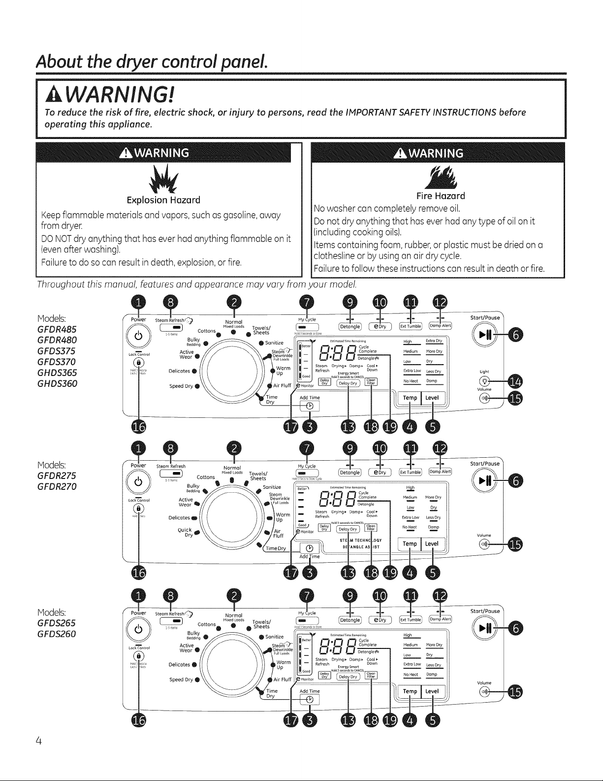
About the dryer control panel.
A WARNING!
To reduce the risk of fire, electric shock, or injury to persons, read the IMPORTANTSAFETYINSTRUCTIONSbefore
operating this appliance.
Explosion Hazard
Keepflammable materials and vapors,such as gasoline,away
from dryer.
DO NOT dry anything that has ever had anything flammable on it
(even after washing).
Failure to do so can result in death, explosion, or fire.
Throughout this manual, features and appearance may vary from your model.
Hodels:
GFDR485
GFDR480
GFDS$75
GFDS370
GHDS365
GHDS$60
Models:
GFDR275
GFDR270
DelicatesO
Speed Dry_
Nowasher cancompletely removeoil.
Donot dry anything that hasever had anytype of oil on it
(includingcooking oils).
Itemscontaining foam, rubber,or plastic must bedried on a
clotheslineor byusingan air dry cycle.
Failureto follow these instructions can resultin death or fire.
Ny Cycle ..................................................
st_m_ted Time Remair ag
_ i _ _ Cycle
CI CI C1......... _,°__...._,y
CI,O O_ Low
Steam Drying_ Damp_ Cool_
Refresh Down ExtraLOW Less Dry
I Cycle
Complete
Fire Hazard
Start/Pause %
0
Light
Volume
StartJPause _
0
Hodels:
GFDS255
GFDS250
Power Steam Refresh_) Normal Hy Cycle
I terns
Lock'_ontrol Active
Cottons _ Sheets _o__s_o,_tos_r_
Bulky
Bedding _ 0 Sanitize
Wear
Delicates
Speed DW_
MixedCoeds Towels/
_O._G ..........
::1!!"/TempILevelANGLE T L__ _ ___
.............................x m am er
I Cyde
Complete Hore Dry
Dry
Damp
Volume
_m
Start/Pause %
0
Volume
0
Control settings.
GEAppliances.com
Hodels:
GFD5255
GFD5250
_er Ste_sh_
£iems
(_ Cottons 0
Lock_ontrol Active
Deticates
Speed Dry
Bulky
8eddlng
Wear
Time Add Time
-- %
Start/Pause
VoJume
®--0
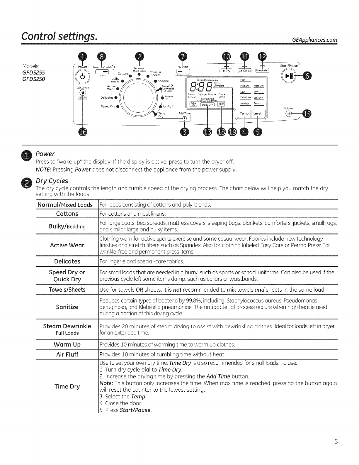
Power
Press to "wake up" the display. If the display is active, press to turn the dryer off.
NOTE: Pressing Power does not disconnect the appliance from the power supply.
Dry Cycles
The dry cycle controls the length and tumble speed af the drying process. The chart below will help yau match the dry
setting with the loads.
Normal/Mixed Loads Forloads consisting of cottons and poly-blends.
Cottons Farcottons and most linens.
Farlarge coats, bed spreads,mattress covers,sleeping bugs, blankets,comforters, jackets, small rugs,
Bulky/Bedding and similar large and bulky items.
Clothing worn for active sports exerciseand some casual wear. Fabricsincludenew technology
Active Wear finishes and stretch fibers such as Spandex.Alsofor clothing labeled EasyCareor Permu Press:For
wrinkle-free and permanent press items.
Delicates Forlingerie and special-carefabrics.
0
Speed Dry or For small loads that are needed in a hurry, such assports or school uniforms. Canalso be used if the
Quick Dry Dreviouscycleleft some items damp, such ascollars or waistbands.
Towels/Sheets Usefor towels ORsheets. It is not recommended to mix towels and sheets in the same load.
Reducescertain types of bacteria by 99.8%,including: Staphylococcus aureus, Pseudomonas
Sanitize aeruginosa, and Klebsiellapneumoniae. Theantibacterial process occurs when high heat is used
during a portion of this drying cycle.
Steam Dewrinkle Provides 20 minutes of steam drying to assist with dewrinkling clothes. Idealfor loads left indryer
FullLoads for an extended time.
Warm Up Provides10 minutes of warming time to warm up clothes.
Air Fluff Provides 10 minutes of tumbling time without heat.
Useto set your own dry time. Time Dry isalso recommended for small loads.To use:
i. Turn dry cycle dial to Time Dry.
2. Increase the drying time by pressing the Add Time button.
Time Dry
Note: This button only increases the time. When max time is reached, pressing the button again
will reset the counter to the lowest setting.
3. Select the Temp.
4. Close the door.
5. PressSturt/Pause.
Control settings.
Add Time
®1
[
Temp I
Level
!
)
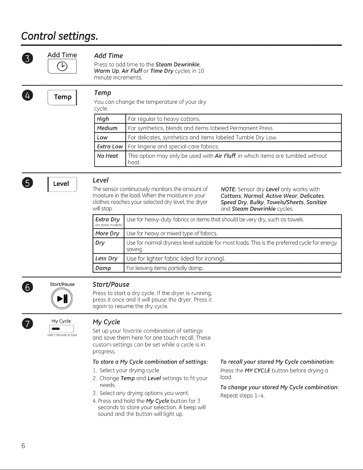
Add Time
Press to add time to the Steam Dewrinkle,
Warm Up, Air Fluff or Time Dry cycles in !0
minute increments.
Temp
You can change the temperature of your dry
cycle.
High
Medium
Low
Extra Low
No Heat
Level
Thesensor continuously monitors the amount of
moisture in the load. When the moisture inyour
clothes reaches your selected dry level,the dryer
will stop.
Extra Dry Usefor heavy-duty fabrics or items that should be very dry,such astowels.
(on some models)
More Dry Use for heavy or mixed type offabrics.
Dry Usefor normal drynesslevelsuitable for most loads.This isthe preferred cycle for energy
Less Dry Use for lighter fabric (ideal for ironing).
Damp Forleaving items partially damp.
For regular to heavy cottons.
For synthetics, blends and items labeled Permanent Press.
For delicates, synthetics and items labeled Tumble Dry Low.
For lingerie and special-care fabrics.
This option may only be used with Air Fluff, in which items are tumbled without
heat.
NOTE: Sensor dry Level only works with
Cottons, Normal, Active Wear, Delicates,
Speed Dry, Bulky, Towels/Sheets, Sanitize
and Steam Dewrinkle cycles.
saving.
Start/Pause
Ply Cycle
Hold 3 Seconds to Store
Start/Pause
Press to start a dry cycle. If the dryer is running,
press it once and it will pause the dryer. Press it
again to resume the dry cycle.
My Cycle
Set up your favorite combination of settings
and save them here for one touch recall. These
custom settings can be set while a cycle is in
progress.
To store a Ply Cycle combination of settings:
!. Select your drying cycle.
2. Change Temp and Level settings to fit your
needs.
3. Select any drying options you want.
4. Pressand hold the My Cycle button for 3
seconds to store your selection. A beep will
sound and the button will light up.
To recall your stored Ply Cycle combination:
Pressthe PlYCYCLEbutton before drying a
load.
To change your stored Ply Cycle combination:
Repeat steps !-/4.
GEAppliances.com
Steam RefreshC
_-5terns
!
Detangil
!
[EXtTUmb!e
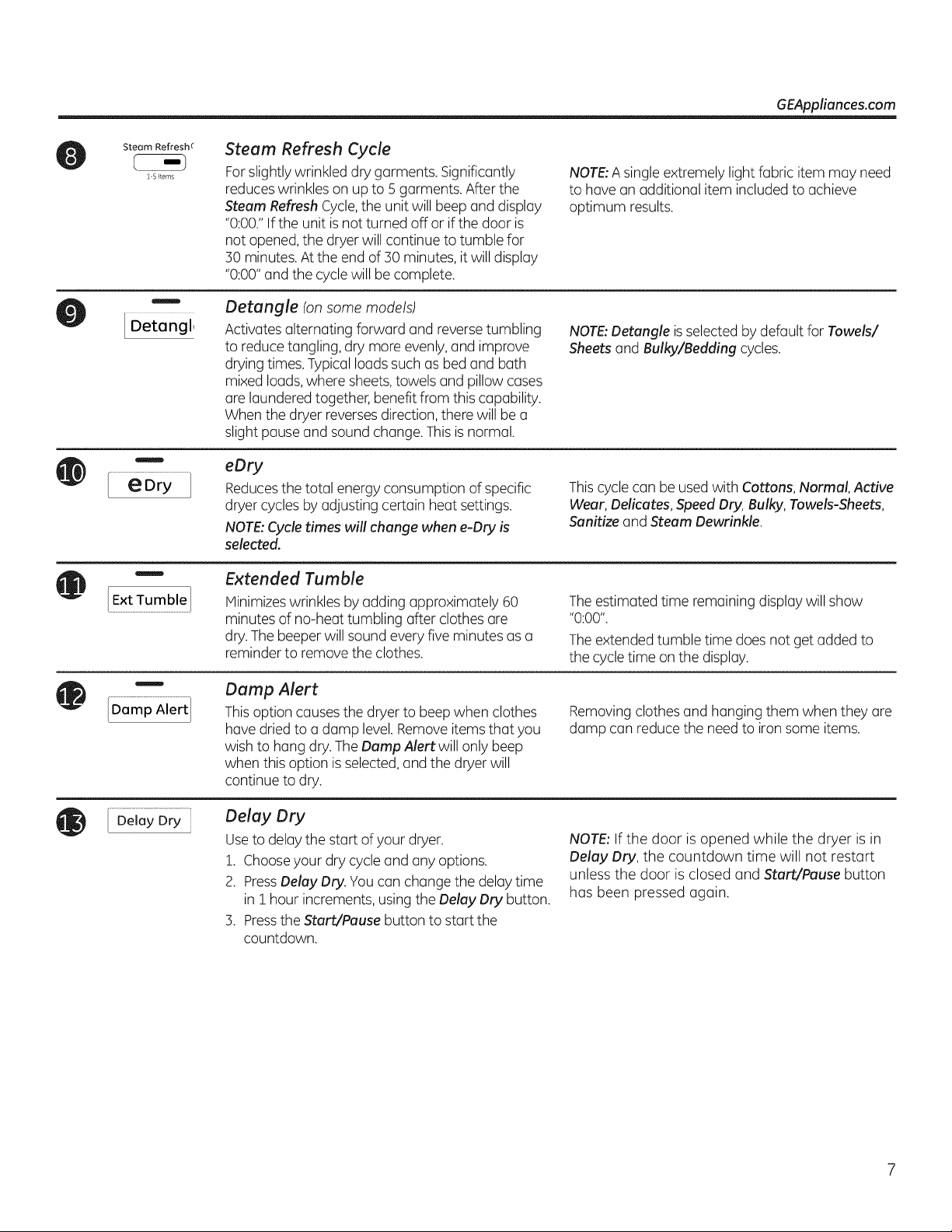
Steam Refresh Cycle
Forslightly wrinkled dry garments. Significantly
reduceswrinkles on up to 5 garments. After the
Steam Refresh Cycle,the unit will beep and display
"0:00."If the unit is not turned off or ifthe door is
not opened,the dryer will continue to tumble for
30 minutes. At the end of 30 minutes, itwill display
"0:00" and the cyclewill be complete.
Detangle (on some models)
Activates alternating forward and reversetumbling
to reduce tangling, dry more evenly,and improve
drying times.Typical loadssuch as bedand bath
mixed loads, where sheets,towels and pillow cases
are laundered together, benefit from this capability.
When the dryer reversesdirection,there will be a
slight pause and sound change. Thisis normal.
eDry
Reducesthe total energy consumption of specific
dryer cycles by adjusting certain heat settings.
NOTE: Cycle times will change when e-Dry is
selected.
Extended Tumble
Minimizeswrinkles by adding approximately 60
minutes of no-heat tumbling after clothes are
dry. The beeper will sound every five minutes as a
reminder to remove the clothes.
NOTe A singleextremely light fabric item may need
to have an additional item included to achieve
optimum results.
NOTE:Detangle isselected bydefault for Towels/
Sheets and Bulky/Bedding cycles.
Thiscyclecan be used with Cottons, Normal, Active
Wear, Delicates, Speed Dry, Bulky, Towels-Sheets,
Sanitize and Steam Dewrinkle.
Theestimated time remaining display will show
"0:00".
Theextended tumble time does not get added to
the cycletime on the display.
Damp Alert
Thisoption causesthe dryer to beepwhen clothes
hove dried to a damp level.Removeitems that you
wish to hang dry. TheDamp Alert will only beep
when this option is selected,and the dryer will
continue to dry.
Delay Dry
Use to delay the start of your dryer.
1. Choose your dry cycle and any options.
2. Press Delay Dry. Youcan change the delay time
in i hour increments, using the Delav Dry button.
3. Press the Start/Pause button to start the
countdown.
Removingclothes and hanging them when they are
damp can reduce the need to iron some items.
NOTE:If the door is opened while the dryer is in
Delay Dry, the countdown time will not restart
unless the door is closed and Start/Pause button
has been pressed again.
Control settings.
Light
@
Volume
B
LockControl
®
Hold 3Secsto
Lock / Unlock
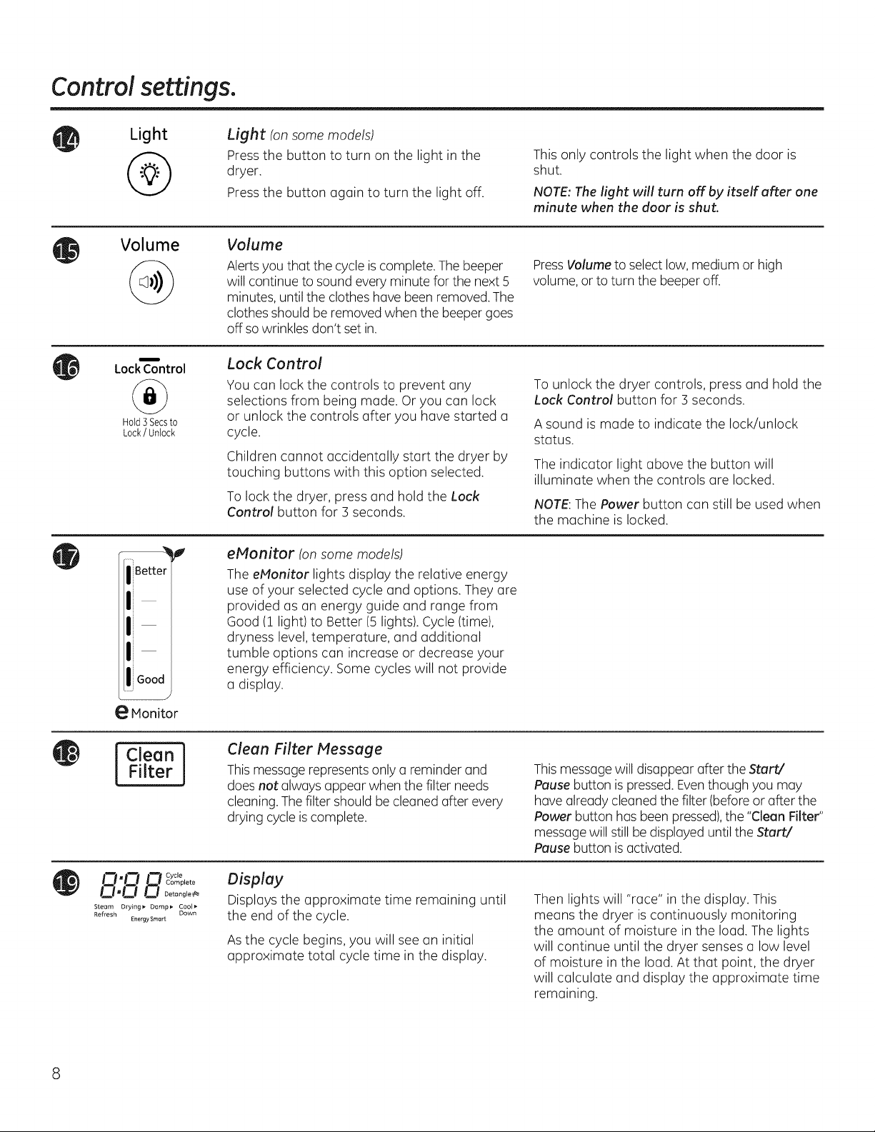
Light (on some models)
Press the button to turn on the light in the
dryer.
Press the button again to turn the light off.
Volume
Alerts you that the cycle iscomplete. The beeper
will continue to sound every minute for the next 5
minutes, until the clothes have been removed.The
clothes should be removed when the beeper goes
off so wrinkles don't set in.
Lock Control
You can lock the controls to prevent any
selections from being made. Or you can lock
or unlock the controls after you have started a
cycle.
Children cannot accidentally start the dryer by
touching buttons with this option selected.
To lock the dryer, press and hold the Lock
Control button for 3 seconds.
This only controls the light when the door is
shut.
NOTE:The light will turn off by itself after one
minute when the door is shut.
PressVolume to select low, medium or high
volume, or to turn the beeper off.
To unlock the dryer controls, press and hold the
Lock Control button for 3 seconds.
A sound is made to indicate the lock/unlock
status.
The indicator light above the button will
illuminate when the controls are locked.
NOTE:The Power button can still be used when
the machine is locked.
g
e Monitor
Filter
Clean i
O'O n cyc'°
0"0 Q Detangle_
Steam Drying_ Damp_ Cool_
Refresh Down
Complete
Energy Smart
eMonitor (on some models)
The eMonitor lights display the relative energy
use of your selected cycle and options. They are
provided as an energy guide and range from
Good (1 light) to Better (5 lights). Cycle (time),
dryness level, temperature, and additional
tumble options can increase or decrease your
energy efficiency. Some cycles will not provide
a display.
Clean Filter Message
This message represents only a reminder and
does not always appear when the filter needs
cleaning. The filter should be cleaned after every
drying cycle is complete.
Display
Displays the approximate time remaining until
the end of the cycle.
Asthe cycle begins, you will see an initial
approximate total cycle time in the display.
This message will disappear after the Start/
Pause button is pressed. Eventhough you may
have alreadycleaned the filter (before or after the
Power button has been pressed),the "Clean Filter"
messagewill still be displayed until the Start/
Pause button is activated.
Then lights will "race" in the display. This
means the dryer is continuously monitoring
the amount of moisture in the load. The lights
will continue until the dryer senses a low level
of moisture in the load. At that point, the dryer
will calculate and display the approximate time
remaining.
Using the dryer. GEAppliances.com
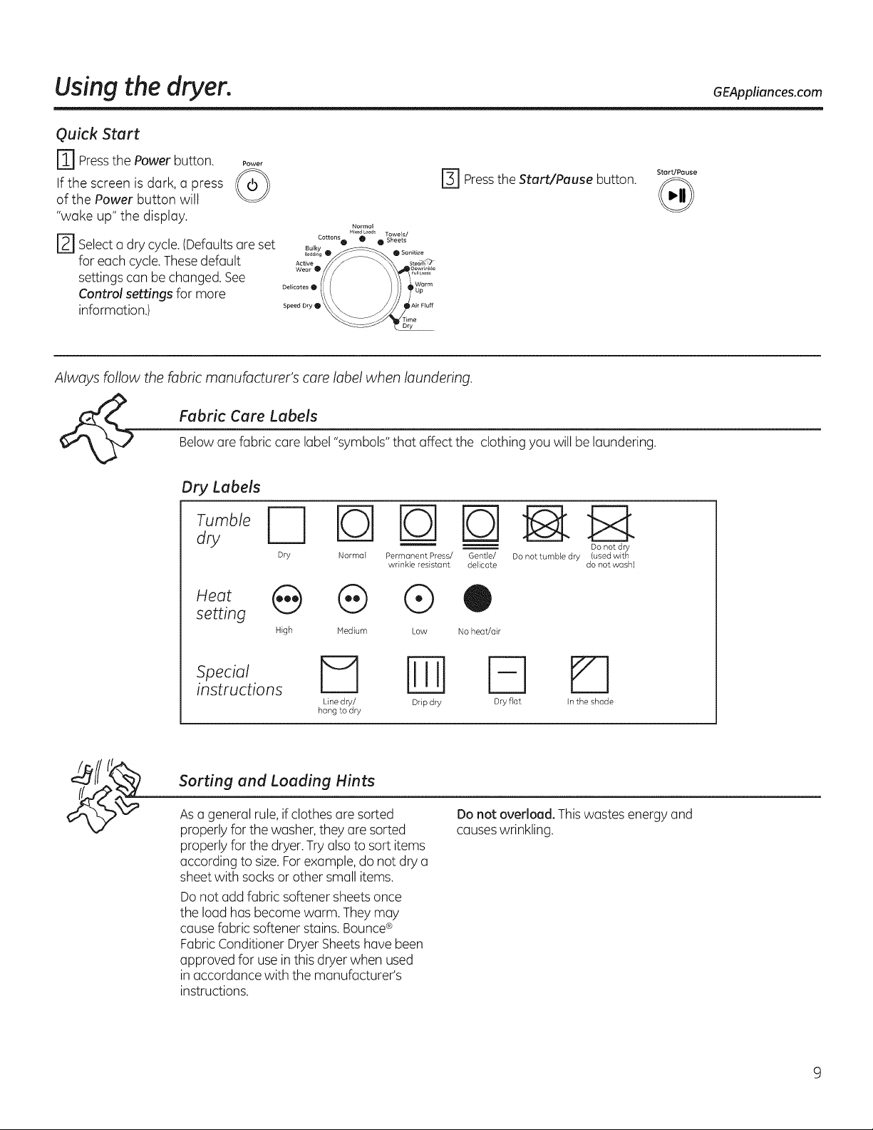
Quick Start
r_ Pressthe Power button.
If the screen is dark, a press
Power
r_ Press the Start/Pause button.
of the Power button will
"wake up" the display.
r_ Selecta dry cycle.(Defaultsare set
for each cycle.Thesedefault
settings can be changed. See
Control settings for more
information.)
Delicates • _U_parm
Speed Dry O
Dry
Always follow the fabric manufacturer's care label when laundering.
Fabric Care LabelsBelow are fabric care label "symbols" that affect the clothing you willbe laundering.
Dry Labels
--'1 _ DOnot dry
Dry Normal Permanent Press/ Gentle/ Do not tumble dry (used with
wrinkle resistant delicate do not wash)
Start/Pause
setting
High Medium Low No heat/air
_Psetcialtions El _] _]
Line dry/ Drip dry Dry fiat In the shade
hang to dry
Sorting and Loading Hints
Asa general rule, if clothes are sorted
properly for the washer,they are sorted
properly for the dryer.Try also to sort items
according to size.Forexample, do not dry a
sheet with socksor other small items.
Do not add fabric softener sheets once
the load has become warm. They may
cause fabric softener stains.Bounce®
Fabric Conditioner Dryer Sheetshave been
approved for use in this dryer when used
in accordance with the manufacturer's
instructions.
Do not overload. Thiswastes energy and
causeswrinkling.
About dryer features.
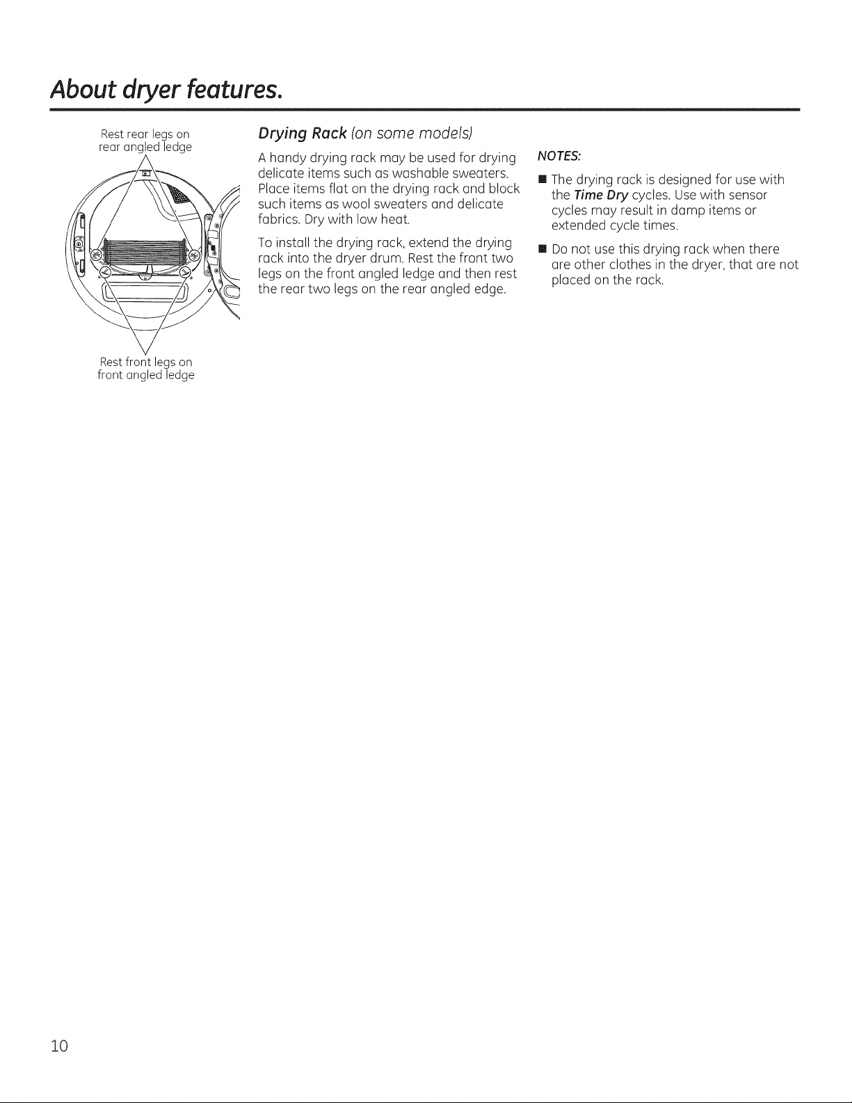
Rest rear legs on
rear angled ledge
Restfront legs on
front angled ledge
Drying Rack (onsome models)
A handy drying rack may be used for drying
delicate items such as washable sweaters.
Place items flat on the drying rack and block
such items as wool sweaters and delicate
fabrics. Dry with low heat.
To install the drying rack, extend the drying
rack into the dryer drum. Rest the front two
legs on the front angled ledge and then rest
the rear two legs on the rear angled edge.
NOTES:
[] The drying rack is designed for use with
the Time OrV cycles. Use with sensor
cycles may result in damp items or
extended cycle times.
[] Do not use this drying rack when there
are other clothes in the dryer, that are not
placed on the rack.
10
Care and Cleaning of the Dryer. GEAppliances.com
The Exterior'. Wipe or dust any spills or
washing compounds with a dump cloth.
Dryer control panel and finishes may be
damaged by some laundry pretreatment
soiland stain remover products. Applythese
products away from the dryer. The fabric
may then be washed and dried normally.
Damage to your dryer caused by these
products is not covered by your warranty.
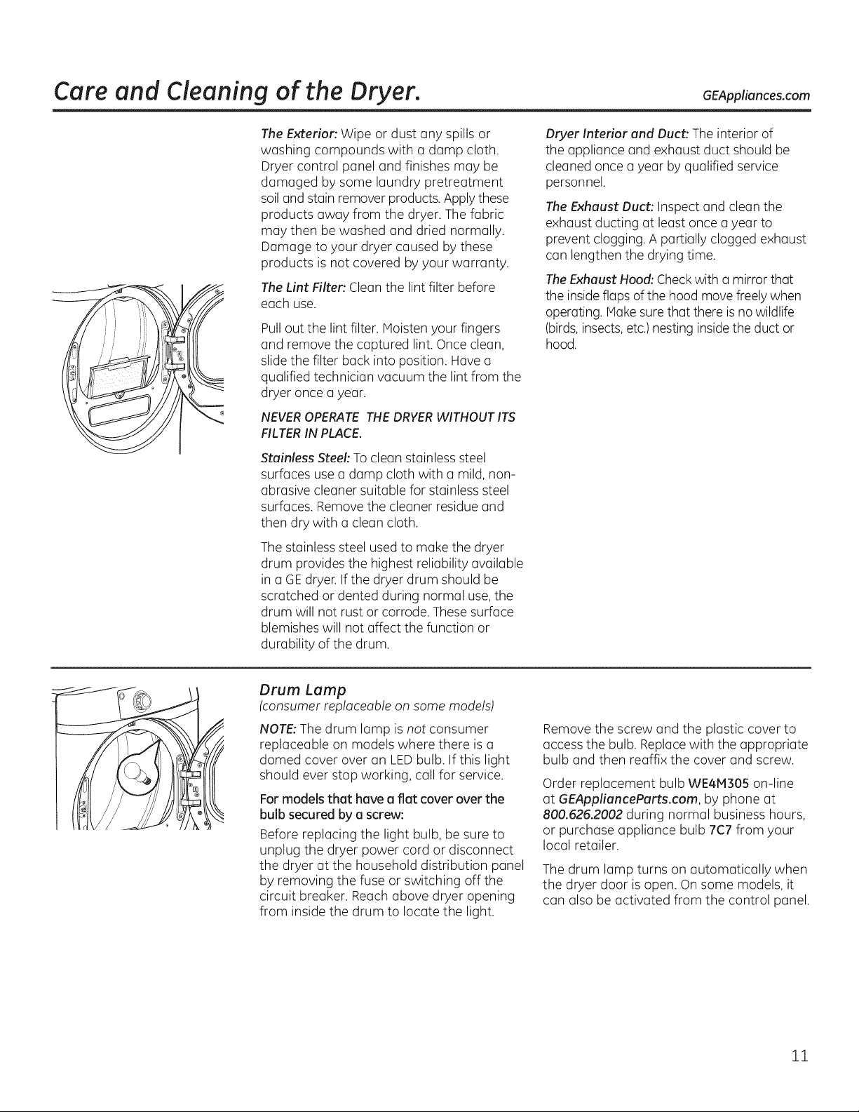
The Lint Filter'. Clean the lint filter before
each use.
Pull out the lint filter. Moisten your fingers
and remove the captured lint. Once clean,
slide the filter back into position. Have a
qualified technician vacuum the lint from the
dryer once a year.
NEVER OPERATE THE DRYER WITHOUT ITS
FILTER IN PLACE.
Stainless Steel: To clean stainless steel
surfaces usea damp cloth with a mild, non-
abrasive cleaner suitable for stainless steel
surfaces. Removethe cleaner residue and
then dry with a clean cloth.
Thestainless steel used to make the dryer
drum provides the highest reliability available
in a GEdryer. If the dryer drum should be
scratched or dented during normal use, the
drum will not rust or corrode. These surface
blemishes will not affect the function or
durability of the drum.
Drver Interior and Duct: The interior of
the appliance and exhaust duct should be
cleaned once a year by qualified service
personnel.
The Exhaust Duct: Inspect and clean the
exhaust ducting at least once a year to
prevent clogging. A partially clogged exhaust
can lengthen the drying time.
TheExhaust Hood: Checkwith a mirror that
the insideflaps of the hood move freely when
operating. Make surethat there is no wildlife
(birds,insects,etc.) nesting insidethe duct or
hood.
Drum Lump
(consumer replaceable on some models)
NOTE:The drum lamp is not consumer
replaceable on models where there is a
domed cover over an LEDbulb. If this light
should ever stop working, call for service.
For models that have a flat cover over the
bulb secured by a screw:
Before replacing the light bulb, be sure to
unplug the dryer power cord or disconnect
the dryer at the household distribution panel
by removing the fuse or switching off the
circuit breaker. Reach above dryer opening
from inside the drum to locate the light.
Remove the screw and the plastic cover to
access the bulb. Replacewith the appropriate
bulb and then reaffix the cover and screw.
Order replacement bulb WE4NI305 on-line
at GEApplianceParts.com, by phone at
800.626.2002 during normal business hours,
or purchase appliance bulb 7C7 from your
local retailer.
The drum lamp turns on automatically when
the dryer door is open. On some models, it
can also be activated from the control panel.
11
Installati
n
Dryers
Instructi
Questions? Call 800.GE.CARES (800.432.2737) or visit our Web site at: GEAppliances.com
In Canada, call 1.800.561.3344 or visit www.GEAppliances.ca
_4_ Thisis the safety alert symbol.Thissymbol alertsyou to potential hazardsthat can killyou or hurt you and others.
Allsafety messageswill follow the safety alert symbol and the word "DANGER","WARNING",or"CAUTION".These
words are defined as:
Indicates a hazardous situation which, if not avoided, will result in death or serious injury.
Indicates a hazardous situation which, if not avoidec could resultin death or serious injury.
_ Indicates a hazardous situation which, if not avoidec could resultin minor or moderate inJury.
BEFORE YOU BEGIN
Readthese instructions completely and carefully.
• IMPORTANT- Savethese instructions for local
electrical inspector's use.
• IMPORTANT- Observeall governing codes and
ordinances.
• Installthe clothes dryer according to the manufacturer's
instructions and local codes.
• Note to Installer - Be sure to leave these instructions
with the Consumer.
• Note to Consumer - Keepthese instructions for future
reference.
• Clothes dryer installation must be performed by a
qualified installer.
• Thisdryer must be exhausted to the outdoors.
, Before the old dryer is removed from service or
discarded, remove the dryer door.
, Service information and the wiring diagram are located
in the control console.
, Do not allow children on or in the appliance. Close
supervision of children is necessary when the appliance
isused near children.
, Proper installation is the responsibility of the installer.
, Product failure due to improper installation isnot
covered under the Warranty.
• Install the dryer where the temperature is above 50°F
for satisfactory operation of the dryer control system.
, Remove and discard existing plastic or metal foil duct
and replace with UL-listed duct.
ns
- Fire Hazard
• Clothes dryer installation must be performed by a
qualified installer.
• Install the clothes dryer according to these
instructions and local codes.
DO NOT install a clothes dryer with flexible plastic
venting materials. If flexible metal (semi-rigid or
foil-type) duct is installed, it must be UL-listed and
installed in accordance with the instructions found
in "Connecting the Dryer to House Vent" later in
this manual. Flexible vent materials are known to
collapse, be easily crushed and trap lint. These
conditions will obstruct dryer airflow and increase
the risk of fire.
DO NOT install or store this appliance in any
location where it could be exposed to water or
weather.
To reduce the risk of severe injury or death, follow
all installation instructions.
Save these instructions. (Installers: Be sure to leave
these instructions with the customer.)
12

Installation Instructions
UNPACKING YOUR DRYER
Tilt the dryer sideways and remove the foam
shipping pads by pulling at the sides and breaking
them away from the dryer legs. Be sure to remove all
of the foam pieces around the legs.
Remove the bag containing the literature.
DRYER 28"
DIMENSIONS _ (71.12cm)
Front View
*NOTE: _
With Legs: 40 1/2" (102.5 cm) - (3/4" (1.9cm) adjustability)
With Built-In PedestaF": 46" (117 cm) - (5/4" (1.9 cm) adjustabiFty)
With Optional Pedestal {GF×P1308): 52" (152.1 cm) - (5/4" (1.9 cm) adjustabiFty)
Stacked: 78 1/4" (198.8 cm)
39"* 46"*
(99cm) (llTcm)
STEAM WATER HOSES:
GEstrongly recommends the useof factory specifiedparts.
Thesehoses are manufactured and tested to meet GE
specifications.
GEstrongly recommends the useof new water supply hoses.
Hosesdegrade overtime and need to be replaced every 5
years to reduce the risk of hose failures and water damage.
Parts and Accessories
Order on-line at GEApplianceParts.com, 24 hours aday or by
phone at 800.626.2002during normal businesshours.
54 3/8"* (!38.1cm)
7/8" (83.5cm) I
Side View
Part Number
WE25MB3
OR
WElt4847 Long Hose and
WEl14848 Short Hose
Accessory
CompleteKit(hoses,Y-adapter
washers)(included)
39"* 46"*
(99cm) (117cm)
Built-In
PedestalTM
models
only
J
POWER CORDS:
GEstrongly recommends the useof factory specified parts.
Selectthe power cord to fit your installation requirements.
Order on-line at GEApplianceParts.com, 24 hours aday or
by phone at 800.626.2002during normal businesshours.
Part Number Type Length Amperage
WX9X2 :]-Prong . 4 Feet _ 30
WX9X3 3-Prong 5 Feet 30
WX9X4 :]-Prong 6 Feet 30
WX9X18 4-Prong 4 Feet 30
WX9X19 4-Prong 5 Feet 30
WX9X20 4-Prong 6 Feet 30
13
Instollotion Instructions
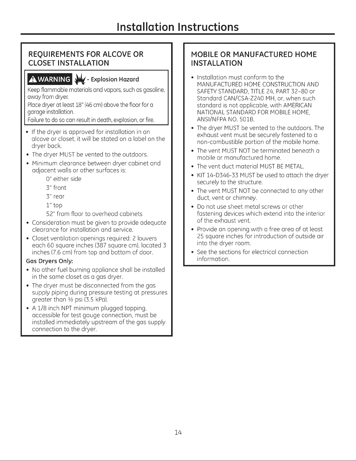
REQUIREMENTS FOR ALCOVE OR
CLOSET INSTALLATION
_- Explosion Hazard
Keepflammable materialsand vapors,suchasgasoline,
awayfrom dryer.
Placedryerat least 18"(46cm)abovethe floorfor a
garageinstallation.
Failuretodo socan resultin death,explosion,orfire.
, If the dryer is approved for installation in an
alcove or closet, it will be stated on a label on the
dryer back.
, The dryer MUST be vented to the outdoors.
, Minimum clearance between dryer cabinet and
adjacent walls or other surfaces is:
0" either side
3" front
3" rear
l" top
52" from floor to overhead cabinets
Consideration must be given to provide adequate
clearance for installation and service.
, Closet ventilation openings required: 2 louvers
each 60 square inches (387 square cm), located 3
inches (7.6 cm) from top and bottom of door.
Gas Dryers Only:
, No other fuel burning appliance shall be installed
in the same closet as a gas dryer.
, The dryer must be disconnected from the gas
supply piping during pressure testing at pressures
greater than 1,_psi (3.5 kPa).
, A 1/8 inch NPT minimum plugged tapping,
accessible for test gauge connection, must be
installed immediately upstream of the gas supply
connection to the dryer.
MOBILE OR MANUFACTURED HOME
INSTALLATION
,, Installation must conform to the
MANUFACTURED HOME CONSTRUCTION AND
SAFETYSTANDARD, TITLE 24, PART32-80 or
Standard CAN/CSA-Z240 MH, or, when such
standard is not applicable, with AMERICAN
NATIONAL STANDARD FOR MOBILE HOME,
ANSI/NFPA NO. 50lB.
, The dryer MUST be vented to the outdoors. The
exhaust vent must be securely fastened to a
non-combustible portion of the mobile home.
,, The vent MUST NOT be terminated beneath a
mobile or manufactured home.
, The vent duct material MUST BE METAL.
,, KIT 14-D346-33 MUST be used to attach the dryer
securely to the structure.
, The vent MUST NOT be connected to any other
duct, vent or chimney.
, Do not use sheet metal screws or other
fastening devices which extend into the interior
of the exhaust vent.
, Provide an opening with a free area of at least
25 square inches for introduction of outside air
into the dryer room.
, See the sections for electrical connection
information.
14
Installation Instructions
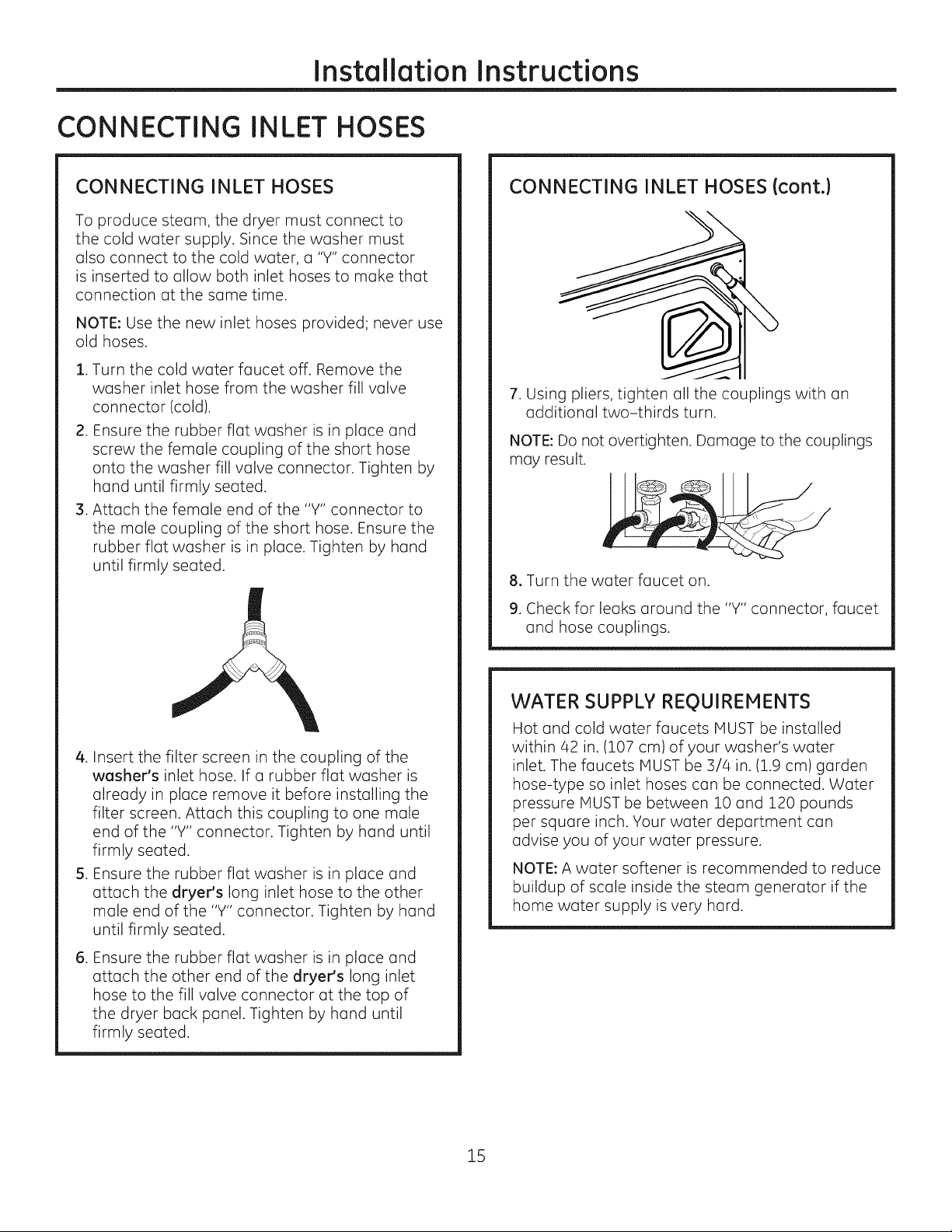
CONNECTING INLET HOSES
CONNECTING INLET HOSES
To produce steam, the dryer must connect to
the cold water supply. Since the washer must
also connect to the cold water, a "Y" connector
is inserted to allow both inlet hoses to make that
connection at the same time.
NOTE: Use the new inlet hoses provided; never use
old hoses.
. Turn the cold water faucet off. Remove the
washer inlet hose from the washer fill valve
connector (cold).
2. Ensure the rubber flat washer is in place and
screw the female coupling of the short hose
onto the washer fill valve connector. Tighten by
hand until firmly seated.
3. Attach the female end of the "Y" connector to
the male coupling of the short hose. Ensure the
rubber flat washer is in place. Tighten by hand
until firmly seated.
CONNECTING INLET HOSES (cont.)
7. Using pliers, tighten all the couplings with an
additional two-thirds turn.
NOTE: Do not overtighten. Damage to the couplings
may result.
8. Turn the water faucet on.
9. Check for leaks around the "Y" connector, faucet
and hose couplings.
4. Insert the filter screen in the coupling of the
washer's inlet hose. If a rubber flat washer is
already in place remove it before installing the
filter screen. Attach this coupling to one male
end of the "Y" connector. Tighten by hand until
firmly seated.
5. Ensure the rubber flat washer is in place and
attach the dryer's long inlet hose to the other
male end of the "Y" connector. Tighten by hand
until firmly seated.
.
Ensure the rubber flat washer is in place and
attach the other end of the dryer's long inlet
hose to the fill valve connector at the top of
the dryer back panel. Tighten by hand until
firmly seated.
WATER SUPPLY REgUIREMENTS
Hot and cold water faucets MUST be installed
within 42 in. (107 cm) of your washer's water
inlet. The faucets MUST be 3/4 in. (1.9 cm) garden
hose-type so inlet hoses can be connected. Water
pressure MUST be between 10 and 120 pounds
per square inch. Your water department can
advise you of your water pressure.
NOTE: A water softener is recommended to reduce
buildup of scale inside the steam generator if the
home water supply is very hard.
15
Installation Instructions
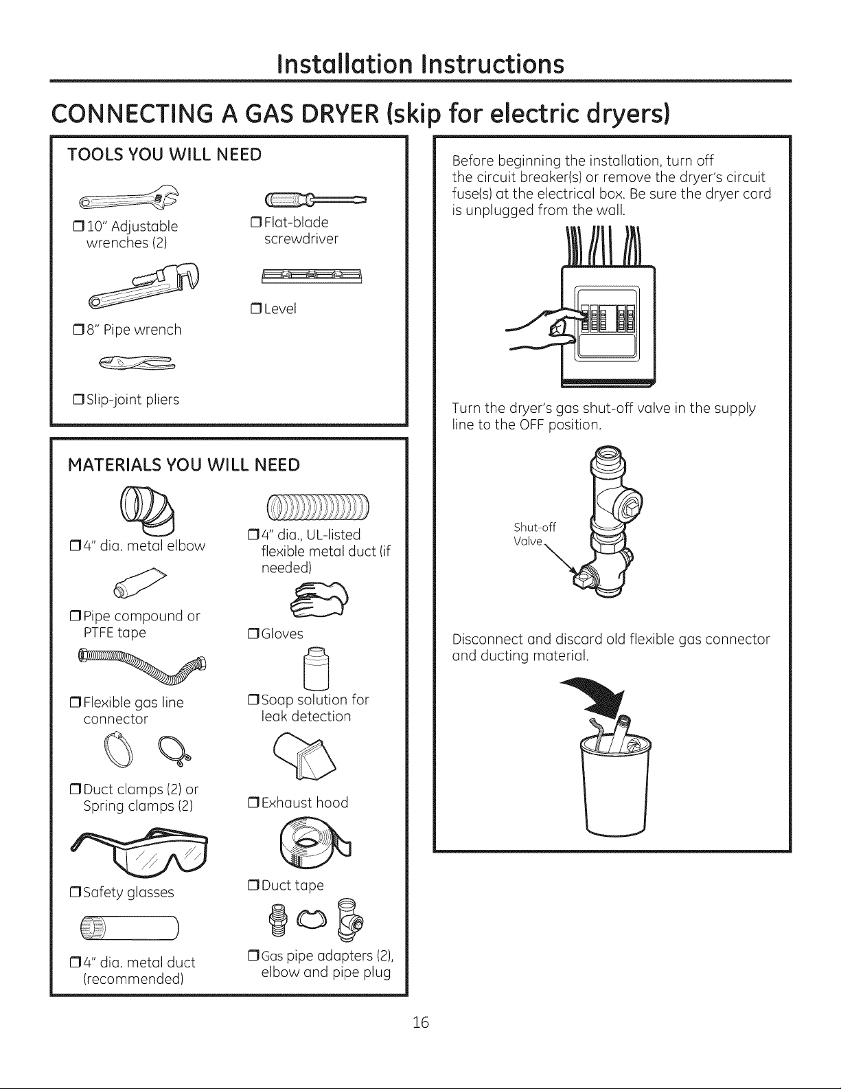
CONNECTING A GAS
TOOLS YOU WILL NEED
17lO" Adjustable
wrenches (2)
178" Pipe wrench
17Slip-joint pliers
MATERIALS YOU WILL NEED
0 Flat-blade
screwdriver
13Level
DRYER(ski
) for electric dryers)
Before beginning the installation, turn off
the circuit breaker(s) or remove the dryer's circuit
fuse(s) at the electrical box. Be sure the dryer cord
is unplugged from the wall.
Turn the dryer's gas shut-off valve in the supply
line to the OFF position.
04" dia. metal elbow
OPipe compound or
PTFEtape
17Flexible gas line
connector
%
17Duct clamps (2) or
Spring clamps (2)
1:3Safety glasses
174" dia., UL-listed
flexible metal duct (if
needed)
17Gloves
0
C1Soap solution for
leak detection
13Exhaust hood
17Duct tape
Shut-off
Valve
Disconnect and discard old flexible gas connector
and ducting material.
}
04" dia. metal duct
(recommended)
OGas pipe adapters (2),
elbow and pipe plug
16
Installation Instructions
GAS REQUIREMENTS
_'- Explosion Hazard
Use a new CSA International approved flexible
gas supply line. Never reuse old flexible
connectors.
o
Install a shut-off valve.
o
Securely tighten all gas connections.
o
If connected to LP gas, have a qualified person
make sure gas pressure does not exceed 13"
water column.
. Examples of a qualified person include: licensed
heating personnel, authorized gas company
personnel, and authorized service personnel.
. Failure to do so can result in death, explosion,
or fire.
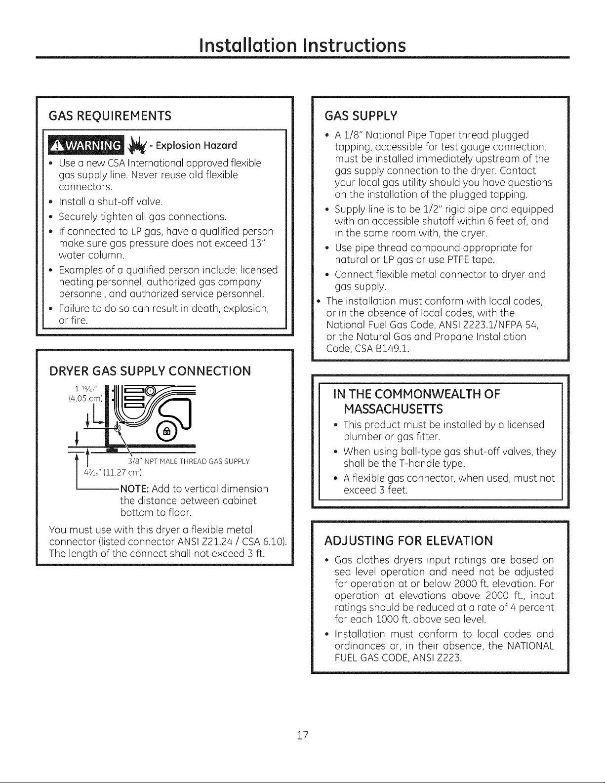
DRYER GAS SUPPLY CONNECTION
i i%2"
(4.05 cm)
47/ld ' (11.27 cm)
t 3/8" NPT MALE THREAD GAS SUPPLY
NOTE: Add to vertical dimension
the distance between cabinet
bottom to floor.
GAS SUPPLY
, A 1/8" National Pipe Taper thread plugged
tapping, accessible for test gauge connection,
must be installed immediately upstream of the
gas supply connection to the dryer. Contact
your local gas utility should you have questions
on the installation of the plugged tapping.
, Supply line is to be 1/2" rigid pipe and equipped
with an accessible shutoff within 6 feet of, and
in the same room with, the dryer.
, Use pipe thread compound appropriate for
natural or LP gas or use PTFEtape.
, Connect flexible metal connector to dryer and
gas supply.
The installation must conform with local codes,
or in the absence of local codes, with the
National Fuel Gas Code, ANSI Z223.1/NFPA 54,
or the Natural Gas and Propane Installation
Code, CSA B149i.
IN THE COMMONWEALTH OF
MASSACHUSETTS
. This product must be installed by a licensed
plumber or gas fitter.
. When using ball-type gas shut-off valves, they
shall be the T-handle type.
. A flexible gas connector, when used, must not
exceed 3 feet.
You must use with this dryer a flexible metal
connector (listed connector ANSI Z21.24 / CSA 6i0).
The length of the connect shall not exceed 3 ft.
ADJUSTING FOR ELEVATION
Gas clothes dryers input ratings are based on
sea level operation and need not be adjusted
for operation at or below 2000 ft. elevation. For
operation at elevations above 2000 ft., input
ratings should be reduced at a rate of 4 percent
for each 1000 ft. above sea level.
Installation must conform to local codes and
ordinances or, in their absence, the NATIONAL
FUEL GAS CODE, ANSI Z223.
17

Installation Instructions
CONNECTING A GAS DRYER (cont,)
CONNECTING THE DRYER TO THE GAS
SUPPLY
Install a female 3/8" NPT elbow at the end of the
@
dryer gas inlet.
Install a 3/8" flare union adapter to the female
elbow.
IMPORTANT: Use a pipe wrench to securely hold
on to the end of the dryer gas inlet to prevent
twisting the inlet.
NOTE: Apply pipe compound or PTFEtape to the
threads of the adapter and dryer gas inlet.
New Metal
Flexible Gas
Line Connector
Ada
]/8" NPT
Items not supplied
rB1 Attach the flexible metal gas line connector to
the adapter.
Adapter
!/8" NPT
Pipe Plug for
Checking Gas
Inlet Pressure
Shut-Off Valve
Pipe size at
least 1/2"
CONNECTING THE DRYERTO THE GAS
SUPPLY(cont.)
@Install a 1/8" NPT plugged tapping to the dryer
gas line shut-off valve for checking gas inlet
pressure.
Install a flare union adapter to the plugged
tapping.
NOTE: Apply pipe compound or PTFEtape
to the threads of the adapter and plugged
tapping.
Apply pipe compound
or PTFEtape to all
male threads.
Shut-Off
Valve
r_ Tighten all connections, using two adjustable
wrenches. Do not overtighten.
Plugged
Apply pipe compound
adapter and dryer gas inlet.
rc1 Tighten the flexible gas line connection, using
two adjustable wrenches.
[] Open the gas shut-off valve.
18
Installation Instructions
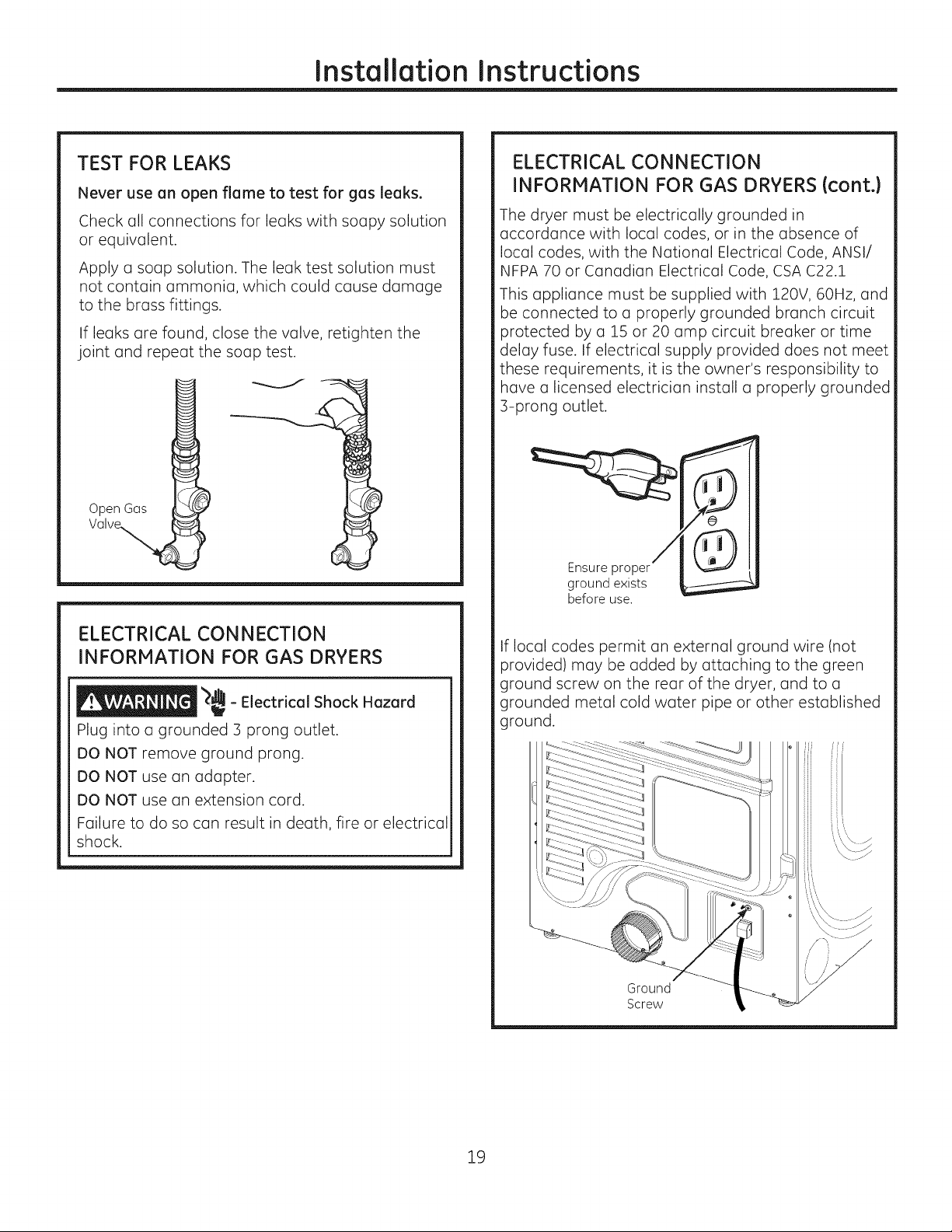
TEST FOR LEAKS
Never use an open flame to test for gas leaks.
Check all connections for leaks with soapy solution
or equivalent.
Apply a soap solution. The leak test solution must
not contain ammonia, which could cause damage
to the brass fittings.
If leaks are found, close the valve, retighten the
joint and repeat the soap test.
Open Gas
ELECTRICAL CONNECTION
INFORMATION FOR GAS DRYERS (cont.}
The dryer must be electrically grounded in
accordance with local codes, or in the absence of
local codes, with the National Electrical Code, ANSI/
NFPA 70 or Canadian Electrical Code, CSA C22.1
This appliance must be supplied with 120V, 60Hz, and
be connected to a properly grounded branch circuit
protected by a 15 or 20 amp circuit breaker or time
delay fuse. If electrical supply provided does not meet
these requirements, it is the owner's responsibility to
have a licensed electrician install a properly grounded
3-prong outlet.
Ensure proper
ground exists
before use.
ELECTRICAL CONNECTION
INFORMATION FOR GAS DRYERS
_ - Electrical Shock Hazard
Plug into a grounded 3 prong outlet.
DO NOT remove ground prong.
DO NOT use an adapter.
DO NOT use an extension cord.
Failure to do so can result in death, fire or electrical
shock.
If local codes permit an external ground wire (not
provided) may be added by attaching to the green
ground screw on the rear of the dryer, and to a
grounded metal cold water pipe or other established
ground.
Ground
Screw
19
Instollotion Instructions
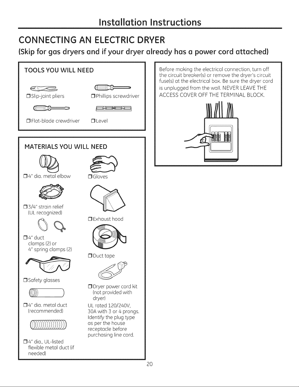
CONNECTING AN ELECTRIC DRYER
(Skip for gos dryers ond if your dryer olreody hos o power cord ottoched)
TOOLS YOU WILL NEED
OSlip-joint pliers 0 Phillips screwdriver
0 Flat-blade crewdriver 0 Level
MATERIALS YOU WILL NEED
04" dia. metal elbow
O3/4" strain relief
(UL recognized)
OGIoves
0 Exhaust hood
Before making the electrical connection, turn off
the circuit breaker(s) or remove the dryer's circuit
fuse(s) at the electrical box. Be sure the dryer cord
is unplugged from the wall. NEVER LEAVE THE
ACCESS COVER OFF THE TERMINAL BLOCK.
04" duct
clamps (2) or
4" spring clamps (2)
0 Safetyglasses
)
O4" dia. metal duct
(recommended)
O4" dia., UL-listed
flexible metal duct (if
needed)
0 Duct tape
O Dryer power cord kit
(not provided with
dryer)
UL rated 120/240V,
30A with 3 or 4 prongs.
Identify the plug type
as per the house
receptacle before
purchasing line cord.
20
Installation Instructions
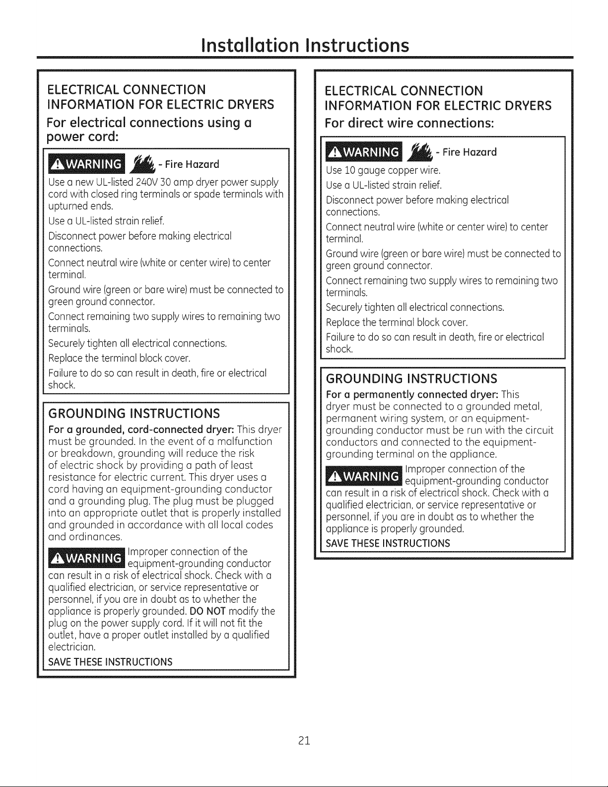
ELECTRICAL CONNECTION
INFORMATION FOR ELECTRIC DRYERS
For electrical connections using a
power cord:
- Fire Hazard
Use a new UL-listed 240V :30amp dryer power supply
cord with closed ring terminals or spade terminals with
upturned ends.
Use a UL-listed strain relief.
Disconnect power before making electrical
connections.
Connect neutral wire (white or center wire) to center
terminal.
Ground wire (green or bare wire) must be connected to
green ground connector.
Connect remaining two supply wires to remaining two
terminals.
Securely tighten all electrical connections.
Replace the terminal block cover.
Failure to do so can result in death, fire or electrical
shock.
GROUNDING INSTRUCTIONS
For a grounded, cord-connected dryer: This dryer
must be grounded. In the event of a malfunction
or breakdown, grounding will reduce the risk
of electric shock by providing a path of least
resistance for electric current. This dryer uses a
cord having an equipment-grounding conductor
and a grounding plug. The plug must be plugged
into an appropriate outlet that is properly installed
and grounded in accordance with all local codes
and ordinances.
Improper connection of the
equipment-grounding conductor
can result in a risk of electrical shock. Check with a
qualified electrician, or service representative or
personnel, if you are in doubt as to whether the
appliance is properly grounded. DO NOT modify the
plug on the power supply cord. If it will not fit the
outlet, have a proper outlet installed by a qualified
electrician.
SAVE THESE INSTRUCTIONS
ELECTRICAL CONNECTION
INFORMATION FOR ELECTRIC DRYERS
For direct wire connections:
- Fire Hazard
Use Z0 gauge copper wire.
Use a UL-Jisted strain relief.
Disconnect power before making electrical
connections.
Connect neutral wire (white or center wire) to center
terminal.
Ground wire (green or bare wire) must be connected to
green ground connector.
Connect remaining two supply wires to remaining two
terminals.
Securely tighten all electrical connections.
Replace the terminal block cover.
Failure to do so can result in death, fire or electrical
shock.
GROUNDING INSTRUCTIONS
For a permanently connected dryer: This
dryer must be connected to a grounded metal,
permanent wiring system, or an equipment-
grounding conductor must be run with the circuit
conductors and connected to the equipment-
grounding terminal on the appliance.
Improper connection of the
equipment-grounding conductor
can result in a risk of electrical shock. Check with a
qualified electrician, or service representative or
personnel, if you are in doubt as to whether the
appliance is properly grounded.
SAVETHESE INSTRUCTIONS
21
Instollotion Instructions
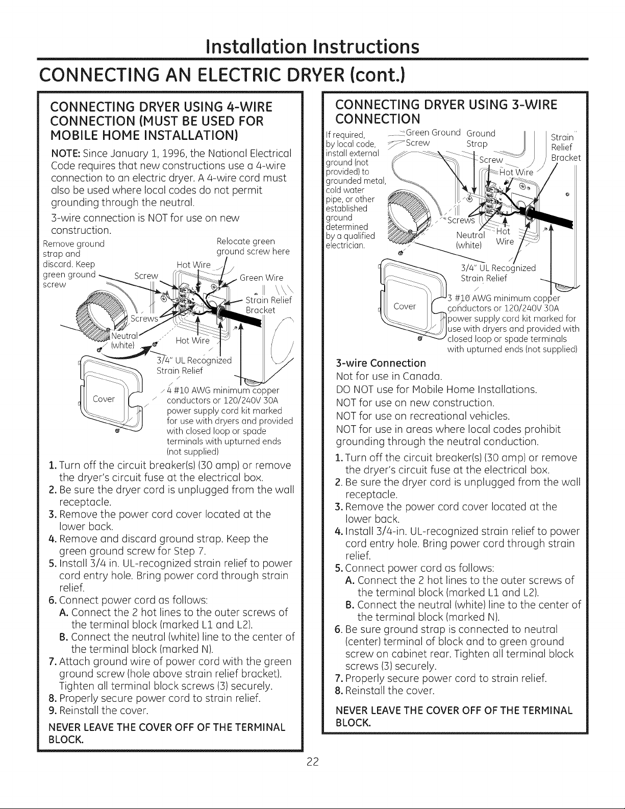
CONNECTING AN ELECTRIC DRYER (cont.)
CONNECTING DRYER USING 4-WIRE
CONNECTION (MUST BE USED FOR
MOBILE HOME INSTALLATION)
NOTE: Since January 1, 1996, the National Electrical
Code requires that new constructions use a 4-wire
connection to an electric dryer. A 4-wire cord must
also be used where local codes do not permit
grounding through the neutral.
3-wire connection is NOT for use on new
construction.
Remove ground Relocate green
strap and ground screw here
discard. Keep Hot Wire
greenground Screw GreenWire
screw
Strain Relief
.-4 #!0 AWG minimum copper
conductors or 120/240V 30A
power supply cord kit marked
for use with dryers and provided
with closed loop or spade
terminals with upturned ends
(not supplied)
1. Turn off the circuit breaker(s) (30 amp) or remove
the dryer's circuit fuse at the electrical box.
2. Be sure the dryer cord is unplugged from the wall
receptacle.
3. Remove the power cord cover located at the
lower back.
4. Remove and discard ground strap. Keep the
green ground screw for Step 7.
5. Install 3/4 in. UL-recognized strain relief to power
cord entry hole. Bring power cord through strain
relief.
6. Connect power cord as follows:
A. Connect the 2 hot lines to the outer screws of
the terminal block (marked LI and L2).
B. Connect the neutral (white)line to the center of
the terminal block (marked N).
7. Attach ground wire of power cord with the green
ground screw (hole above strain relief bracket).
Tighten all terminal block screws (3) securely.
8. Properly secure power cord to strain relief.
9. Reinstall the cover.
NEVER LEAVE THE COVER OFF OF THE TERMINAL
BLOCK.
oII
Strain Relief
Bracket
CONNECTING DRYER USING 3-WIRE
CONNECTION
If required, __ -:Green Ground
by local code, _Screw
install external
ground (not
provided)to
grounded metal,
cold water
pipe,or other
established
ground
determined
by aqualified
electrician.
e"
3-wire Connection
Not for use in Canada.
DO NOT use for Mobile Home Installations.
NOT for use on new construction.
NOT for use on recreational vehicles.
NOT for use in areas where local codes prohibit
grounding through the neutral conduction.
1. Turn off the circuit breaker(s) (30 amp) or remove
the dryer's circuit fuse at the electrical box.
2. Be sure the dryer cord is unplugged from the wall
receptacle.
3. Remove the power cord cover located at the
lower back.
4. Install 3/4-in. UL-recognized strain relief to power
cord entry hole. Bring power cord through strain
relief.
5. Connect power cord as follows:
A. Connect the 2 hot lines to the outer screws of
the terminal block (marked L1 and L2).
B. Connect the neutral (white)line to the center of
the terminal block (marked N).
6. Be sure ground strap is connected to neutral
(center) terminal of block and to green ground
screw on cabinet rear. Tighten all terminal block
screws (3) securely.
7. Properly secure power cord to strain relief.
8. Reinstall the cover.
NEVER LEAVE THE COVER OFF OF THE TERMINAL
BLOCK.
Ground IIII
Strap /11
HotWire "
Strain Relief
J
3 #]O"AWG minimum copper
f
9onductors or !20/240V 30A
3/4" UL Recogn
power supply cord kit marked for
use with dryers and provided with
closed loop or spade terminals
with upturned ends (not supplied)
22
Installation Instructions
EXHAUSTING THE DRYER
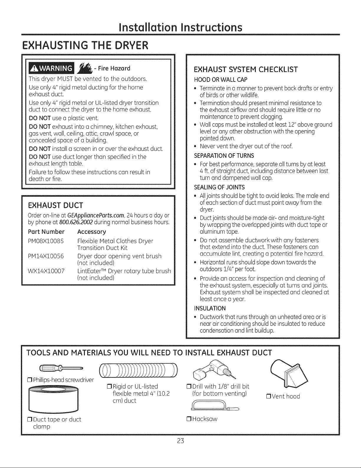
- Fire Hazard
This dryer MUST be vented to the outdoors.
Use only 4" rigid metal ducting for the home
exhaust duct.
Use only 4" rigid metal or UL-listed dryer transition
duct to connect the dryer to the home exhaust.
DO NOT use a plastic vent.
DO NOT exhaust into a chimney, kitchen exhaust,
gas vent, wall, ceiling, attic, crawl space, or
concealed space of a building.
DO NOT install a screen in or over the exhaust duct.
DO NOT use duct longer than specified in the
exhaust length table.
Failure to follow these instructions can result in
death or fire.
EXHAUST DUCT
Order on-line at GEApplianceParts.com, 24 hours a day or
by phone at 800.626.2002 during normal business hours.
Part Number
PMO8XIO085
PMI4XIOO56
WXI4XIO007
Accessory
Flexible Metal Clothes Dryer
Transition Duct Kit
Dryer door opening vent brush
(not included)
LintEater TM Dryer rotary tube brush
(not included)
EXHAUST SYSTEM CHECKLIST
HOOD OR WALL CAP
• Terminate in a manner to prevent back drafts or entry
of birds or other wildlife.
• Termination should present minimal resistance to
the exhaust airflow and should require little or no
maintenance to prevent clogging.
• Wall caps must be installed at least 12" above ground
level or any other obstruction with the opening
pointed down.
• Never vent the dryer out of the roof.
SEPARATIONOFTURNS
• For best performance, separate all turns by at least
4 ft. of straight duct, including distance between last
turn and dampened wall cap.
SEALINGOFJOINTS
• Alljoints should be tight to avoid leaks. The male end
of each section of duct must point away from the
dryer.
• Ductjoints should be made air- and moisture-tight
by wrapping the overlapped joints with duct tape or
aluminum tape.
• Do not assemble ductwork with any fasteners
that extend into the duct. These fasteners can
accumulate lint, creating a potential fire hazard.
• Horizontal runs should slope down towards the
outdoors 1/4" per foot.
Provide an access for inspection and cleaning of
the exhaust system, especially at turns and joints.
Exhaust system shall be inspected and cleaned at
least once a year.
INSULATION
• Ductwork that runs through an unheated area or is
near air conditioning should be insulated to reduce
condensation and lint buildup.
TOOLS AND MATERIALS YOU WILL NEED TO INSTALL EXHAUST DUCT
17Phillips-head screwdriver
17Rigid or UL-listed
flexible metal 4" (10.2
cm) duct
C1Duct tape or duct
clamp
17Drill with 1/8" drill bit
(for bottom venting)
17Hacksaw
23
%
C1Vent hood
Installation Instructions
EXHAUSTING THE DRYER(cont.)
CONNECTING THE DRYER TO HOUSE
VENT
RIGIDMETAL TRANSITION DUCT
• For best drying performance, a rigid metal transition
duct is recommended.
• Rigid metal transition ducts reduce the risk of crushing
and kinking.
UL-LISTEDFLEXIBLEMETAL(SEMI-RIGID}TRANSITION
DUCT
• Ifrigid metal duct cannot be used, then UL-listed
flexible metal (semi-rigid)ducting can be used (Kit
WX08X10077).
• Never install flexible metal duct in walls, ceilings, floors
or other enclosed spaces.
• Total length of flexible metal duct should not exceed 7'
9"(2.4m).
• For many applications, installing elbows at both
the dryer and the wall ishighly recommended (see
illustrations at right). Elbows allow the dryer to sit
close to the wall without kinking and/or crushing the
transition duct, maximizing drying performance.
• Avoid resting the duct on sharp objects.
UL-LISTEDFLEXIBLEMETAL(FaIL-PIPE} TRANSITION
DUCT
• In special installations, it may be necessary to connect
the dryer to the house vent using a flexible metal
(foil-type) duct. A UL-listed flexible metal (foil-type)duct
may be used ONLY in installations where rigid metal or
flexible metal (semi-rigid) ducting cannot be used AND
where a 4" diameter can be maintained throughout
the entire length of the transition duct.
• In Canada and the United States, only the flexible
metal (foil-type) ducts that comply with the "Outline for
Clothes Dryer Transition Duct Subject 2158A" shall be
used.
Never install flexible metal duct in walls, ceilings, floors
or other enclosed spaces.
Total length of flexible metal duct should not exceed 7'
9"12.4m).
Avoid resting the duct on sharp objects.
For best drying performance:
1.Slide one end of the duct over the clothes dryer
outlet pipe.
2.Secure the duct with a clump.
3.With the dryer in its permanent position, extend
the duct to itsfull length. Allow 2" of duct to
overlap the exhaust pipe. Cut off and remove
excess duct. Keep the duct as straight as
possible for maximum airflow.
4.Secure the duct to the exhaust pipe with the
other clump.
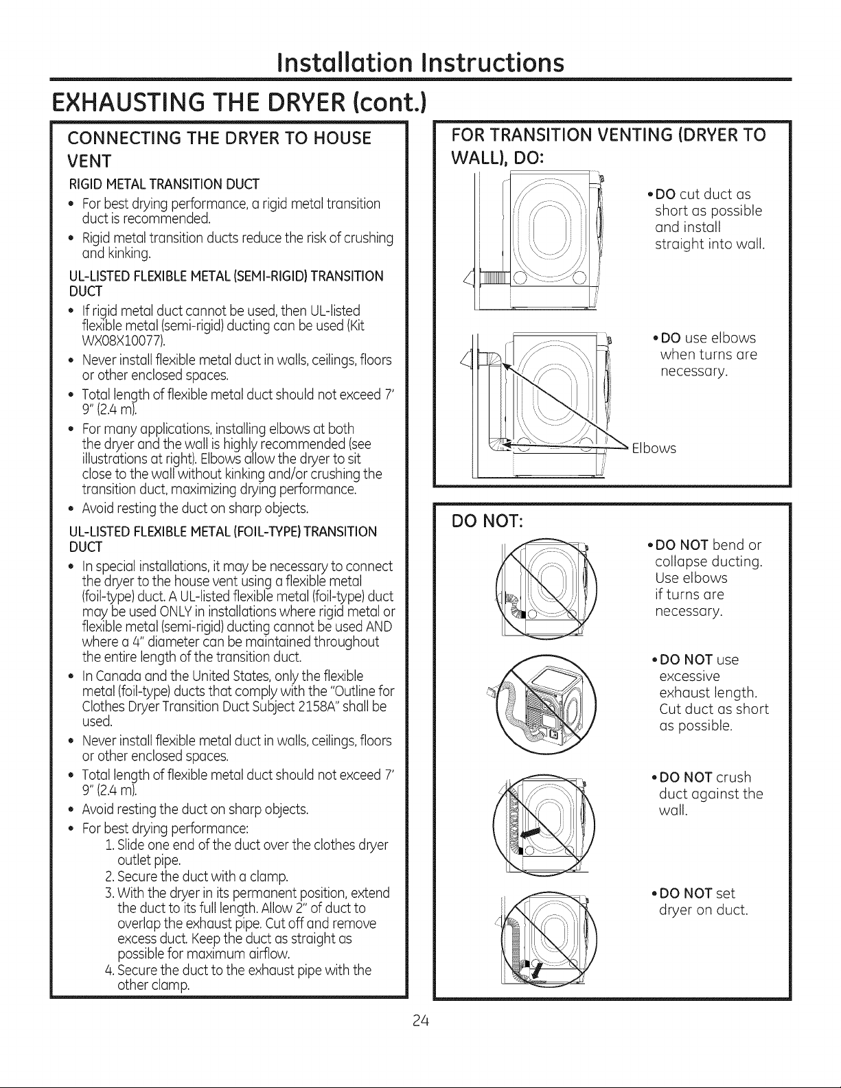
FOR TRANSITION VENTING (DRYER TO
WALL}, DO:
,DO cut duct as
short as possible
and install
straight into wall.
,DO use elbows
when turns are
necessary.
bows
DO NOT:
S_
I
• DO NOT bend or
collapse ducting.
Use elbows
if turns are
necessary.
, DO NOT use
excessive
exhaust length.
Cut duct as short
as possible.
, DO NOT crush
duct against the
wall.
, DO NOT set
dryer on duct.
24
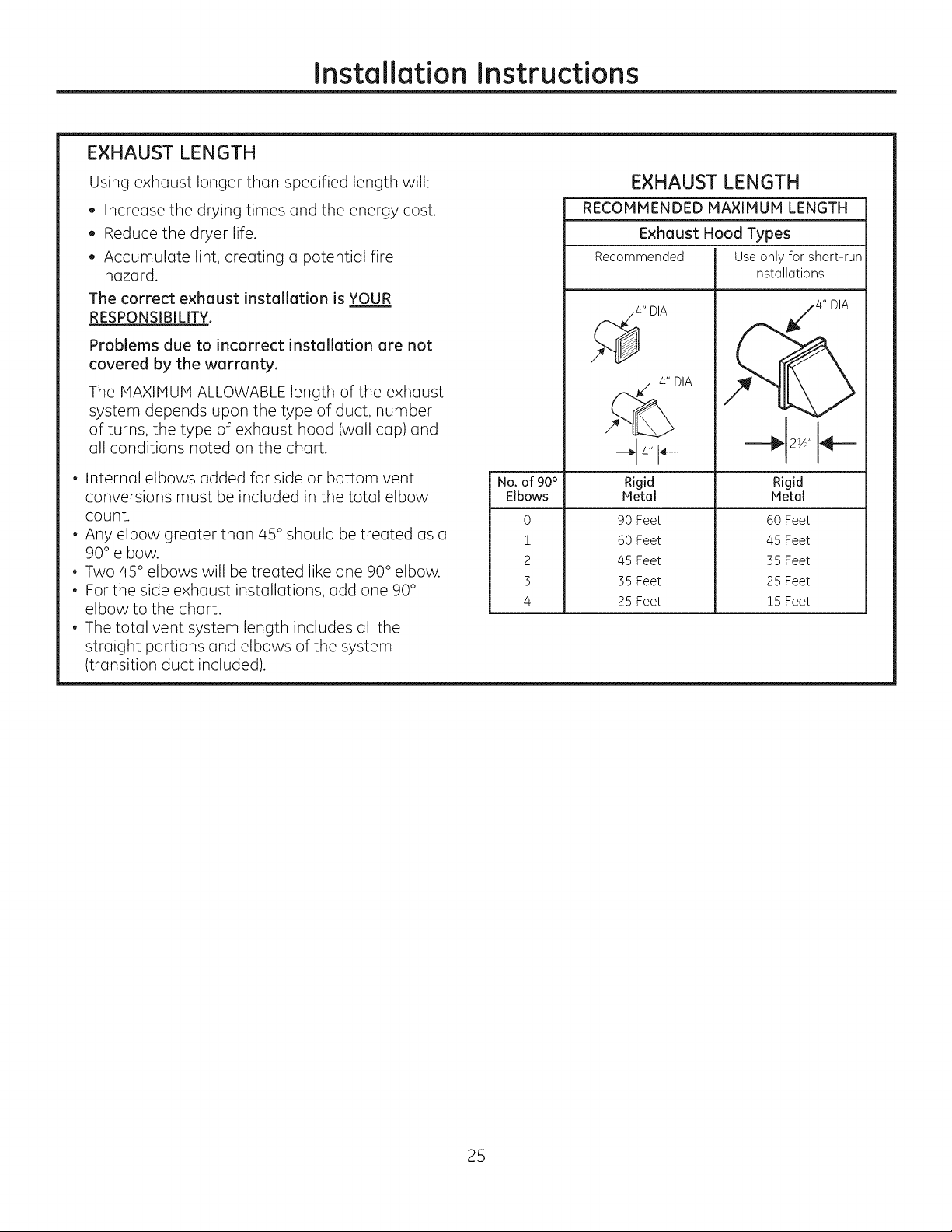
EXHAUST LENGTH
Installation Instructions
Using exhaust longer than specified length will:
, Increase the drying times and the energy cost.
, Reduce the dryer life.
, Accumulate lint, creating a potential fire
hazard.
The correct exhaust installation is YOUR
RESPONSIBILITY.
Problems due to incorrect installation are not
covered by the warranty.
The MAXIMUM ALLOWABLE length of the exhaust
system depends upon the type of duct, number
of turns, the type of exhaust hood (wall cap) and
all conditions noted on the chart.
, Internal elbows added for side or bottom vent
conversions must be included in the total elbow
count.
, Any elbow greater than 45 ° should be treated as a
90° elbow.
, Two 45 ° elbows will be treated like one 90° elbow.
, For the side exhaust installations, add one 90 °
elbow to the chart.
, The total vent system length includes all the
straight portions and elbows of the system
(transition duct included).
No. of 90°
Elbows
0
1
2
3
4
EXHAUST LENGTH
RECOMMENDED MAXIMUM LENGTH
Exhaust Hood Types
Recommended Use only for short-run
4" DIA
4" DIA
installations
/4" DIA
2w'14---
Rigid
Metal
90 Feet
60 Feet
45 Feet
35 Feet
25 Feet
Rigid
Metal
60 Feet
45 Feet
35 Feet
25 Feet
15 Feet
25
Installation Instructions
EXHAUSTING THE DRYER(cont.)
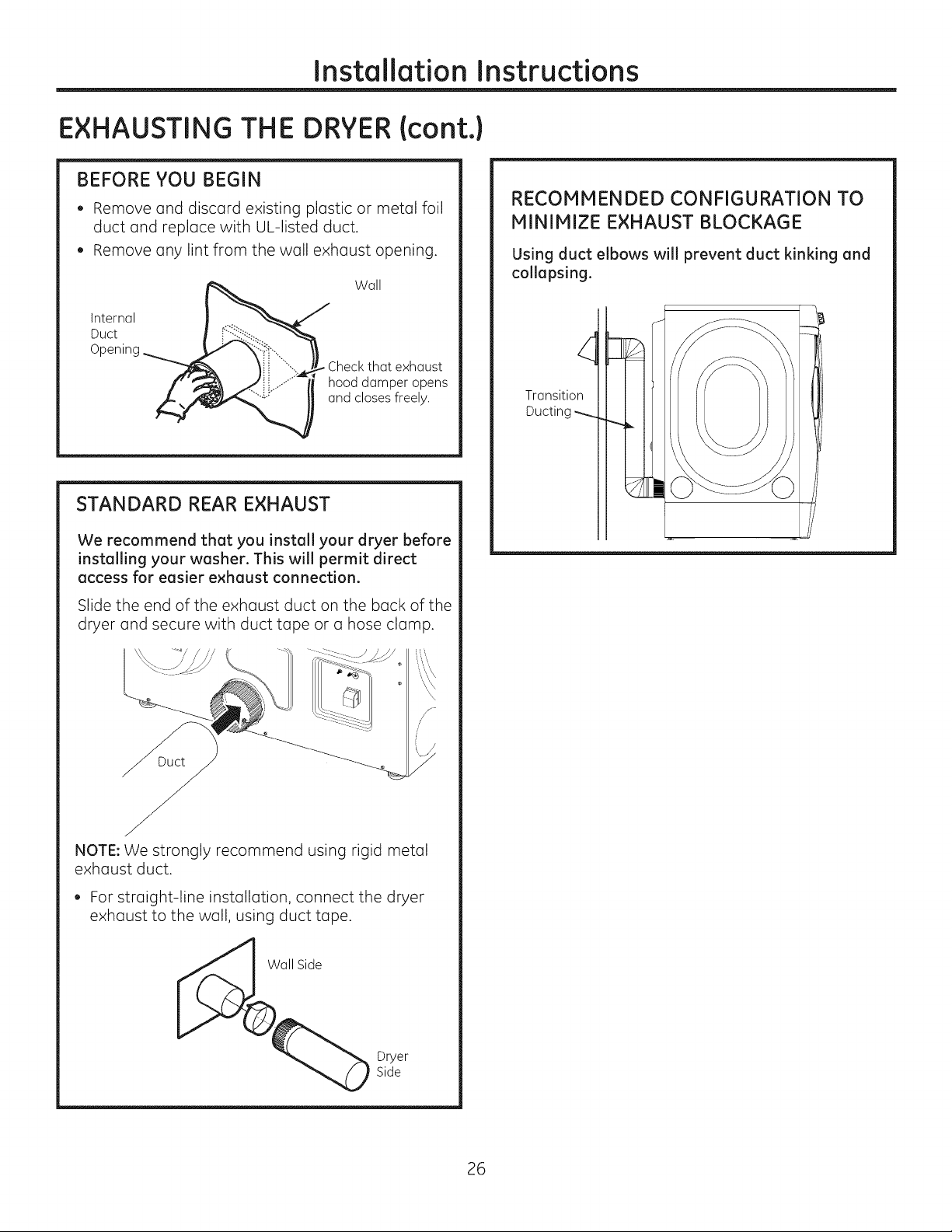
BEFORE YOU BEGIN
, Remove and discard existing plastic or metal foil
duct and replace with UL-listed duct.
, Remove any lint from the wall exhaust opening.
Wall
Internal
Duct
Check that exhaust
hood damper opens
and closes freely.
STANDARD REAR EXHAUST
RECOMMENDED CONFIGURATION TO
MINIMIZE EXHAUST BLOCKAGE
Using duct elbows will prevent duct kinking and
collapsing.
Transition
Ducting
We recommend that you install your dryer before
installing your washer. This will permit direct
access for easier exhaust connection.
Slide the end of the exhaust duct on the back of the
dryer and secure with duct tape or a hose clamp.
\ \
\
,/
r
NOTE: We strongly recommend using rigid metal
exhaust duct.
For straight-line installation, connect the dryer
exhaust to the wall, using duct tape.
all Side
Dryer
Side
26
Installation Instructions
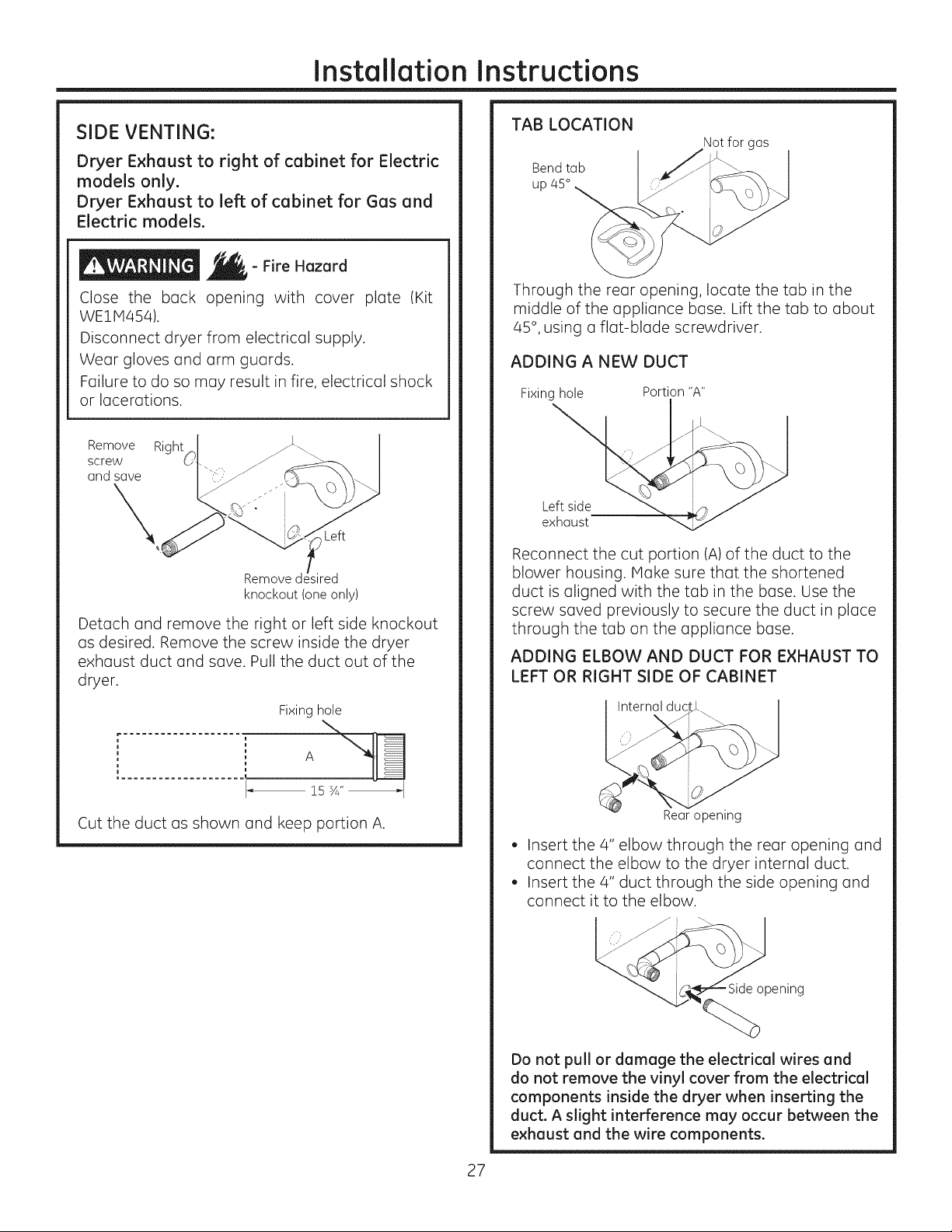
SIDE VENTING:
Dryer Exhaust to right of cabinet for Electric
models only.
Dryer Exhaust to left of cabinet for Gas and
Electric models.
- Fire Hazard
Close the back opening with cover plate (Kit
WEl1454).
Disconnect dryer from electrical supply.
Wear gloves and arm guards.
Failure to do so may result in fire, electrical shock
or lacerations.
Remove Right I
screw _t'- -.
and_ U
Left
Remove
knockout (one only)
Detach and remove the right or left side knockout
as desired. Remove the screw inside the dryer
exhaust duct and save. Pull the duct out of the
dryer.
Fixing hole
.................... "-,,
TAB LOCATION
Notfor gas
Bend tab
up 45°
Through the rear opening, locate the tab in the
middle of the appliance base. Lift the tab to about
45°, using a flat-blade screwdriver.
ADDING A NEW DUCT
Fixing hole Portion "A"
Left side
exhaust
Reconnect the cut portion (A)of the duct to the
blower housing. Make sure that the shortened
duct is aligned with the tab in the base. Use the
screw saved previously to secure the duct in place
through the tab on the appliance base.
ADDING ELBOW AND DUCT FOR EXHAUST TO
LEFT OR RIGHT SIDE OF CABINET
Internal duc
Cut the duct as shown and keep portion A.
Rear opening
, Insert the 4" elbow through the rear opening and
connect the elbow to the dryer internal duct.
, Insert the 4" duct through the side opening and
connect it to the elbow.
opening
Do not pull or damage the electrical wires and
do not remove the vinyl cover from the electrical
components inside the dryer when inserting the
duct. A slight interference may occur between the
exhaust and the wire components.
27

Installation Instructions
EXHAUSTING THE DRYER{cont.)
SIDE VENTING (cont.)
ADDING ELBOW AND DUCT FOR EXHAUST TO
LEFT OR RIGHT SIDE OF CABINET (cont.)
, Apply duct tape as
shown on thejoint
between the dryer
internal duct and the
elbow, and also the joint
between the elbow and
the side duct.
Use 4" rigid metal ducting
only inside the dryer. Internal duct joints must be
secured with tape, otherwise they may separate
and cause a safety hazard.
ADDING COVER PLATE TO REAR OF CABINET
(SIDE EXHAUST)
BOTTOM VENTING:
Dryer Exhaust to the bottom of cabinet for
Gas and Electric models.
- Fire Hazard
Close the back opening with cover plate (Kit
WEllV1454).
Disconnect dryer from electrical supply.
Wear gloves and arm guards.
Failure to do so may result in fire, electrical shock
or lacerations.
Remove
screw
and save
Bottom Rem_ove desired
knockout (one only)
(Kit WE!IVb54)
Connect standard metal elbows and ducts to
complete the exhaust system. Cover back opening
with a plate (Kit WE1P1454) available from your
local service provider. Place dryer in final location.
NEVER LEAVE THE BACK OPENING WITHOUT THE
PLATE. (Kit WEIM454.)
Remove the screw inside the dryer exhaust duct
and save. Pull the duct out of the dryer. Detach
and remove the bottom knockout.
Fixing hole
, A
..................... 15 _Z_
Cut the duct as shown and keep portion A.
28
Installation Instructions
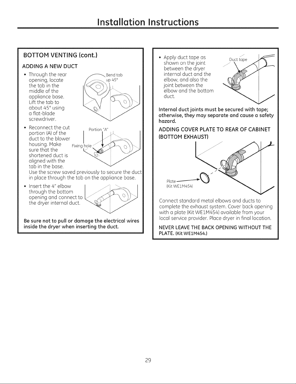
BOTTOM VENTING (cont.)
ADDING A NEW DUCT
o Through the rear
opening, locate
the tab in the
middle of the
appliance base.
Lift the tab to
about 45 ° using
a flat-blade
screwdriver.
Reconnect the cut Portion "A"
portion (A)of the
duct to the blower
housing. Make Fixing
sure that the
shortened duct is
aligned with the
tab in the base.
Use the screw saved previously to secure the duct
in place through the tab on the appliance base.
Insert the/4" elbow
through the bottom
opening and connect to
the dryer internal duct.
Be sure not to pull or damage the electrical wires
inside the dryer when inserting the duct.
Bend tab
up 45°
Apply duct tape as
shown on the joint
between the dryer
internal duct and the
elbow, and also the
joint between the
elbow and the bottom
duct.
Internal duct joints must be secured with tape;
otherwise, they may separate and cause a safety
hazard.
ADDING COVER PLATE TO REAR OF CABINET
(BOTTOM EXHAUST)
Plate -_'_"_'--_ /
(Kit WE1M454)
Connect standard metal elbows and ducts to
complete the exhaust system. Cover back opening
with a plate (Kit WE1M4541 available from your
local service provider. Place dryer in final location.
NEVER LEAVE THE BACK OPENING WITHOUT THE
PLATE. (Kit WEIH454.)
J
Duct tape
29
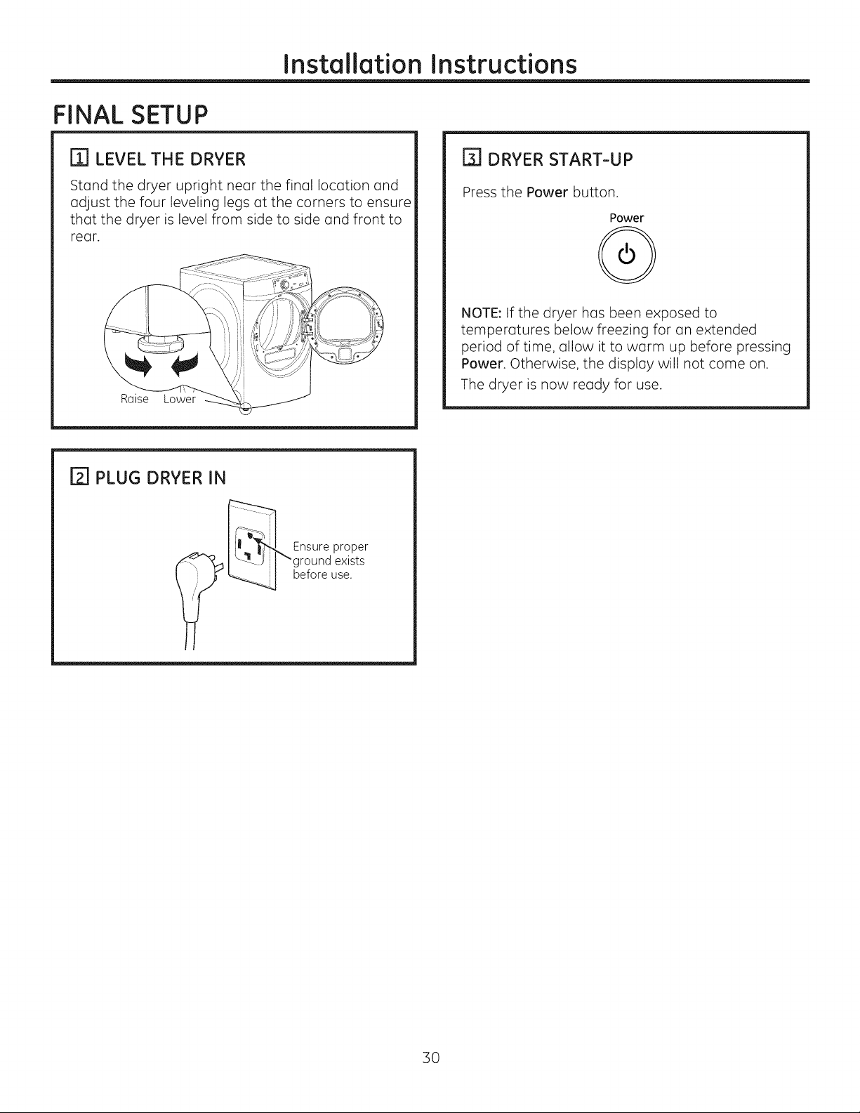
FINAL SETUP
Installation Instructions
[] LEVEL THE DRYER
Stand the dryer upright near the final location and
adjust the four leveling legs at the corners to ensure
that the dryer is level from side to side and front to
rear.
[] PLUG DRYER IN
__-_ Ensure proper
[] DRYER START-UP
Press the Power button.
Power
NOTE: If the dryer has been exposed to
temperatures below freezing for an extended
period of time, allow it to warm up before pressing
Power. Otherwise, the display will not come on.
The dryer is now ready for use.
L..___ before use.
l _-_J i l "ground exists
]0
 Loading...