


Refrigerators
Bottom Freezer
ge.com
Safety Instructions . . . . . . . . . . .2, 3
Operating Instructions
Additional Features . . . . . . . . . . . . .9
Automatic Icemaker . . . . . . . . . . .12
Controls . . . . . . . . . . . . . . . . . . . .4–6
Crispers and Pans . . . . . . . . . . . . .10
Freezer . . . . . . . . . . . . . . . . . . . . . .11
Shelves and Bins . . . . . . . . . . . . .8, 9
Water Filter . . . . . . . . . . . . . . . . . . .7
Care and Cleaning . . . . . . . .13–15
Installation Instructions
Installing the Refrigerator . . . .17–21 Installing the Water Line . . . . .31–33 Preparing to Install
the Refrigerator . . . . . . . . . . . . . . .16 Removing and Replacing the Freezer Drawer . . . . . . . . . . . .22, 23 Reversing the Door Swing
(Single Door Refrigerator
Models only) . . . . . . . . . . . . . .24–27 Removing and Replacing
the Doors (Double Door Refrigerator Models only) . . . .28–30
Troubleshooting Tips . . . . . . .34–38
Normal Operating Sounds . . . . . .34
Consumer Support
Consumer Support . . . . .Back Cover Performance Data Sheet . . . . . . . .45 Product Registration
for Canadian Customers . . . . .41, 42 Product Registration
for U.S. Customers . . . . . . . . .39, 40 Warranty for Canadian
Customers . . . . . . . . . . . . . . . . . . .43 Warranty for U.S. Customers . . . . .44
Write the model and serial numbers here:
Model # ______________________
Serial # ______________________
Find these numbers on a label on the right side, near the top of the refrigerator compartment.
Owner’s Manual and
Installation Instructions
Models 20 and 22
Congélateur inférieur
Réfrigérateurs
Manuel d’utilisation et d’installation
La section française commence à la page 47
Congelador inferior
Refrigeradores
Manual del propietario y instalación
La sección en español empieza en la página 89
3828JL8069C 197D4618P008 49-60452 01-06 JR

Consumer Support Troubleshooting Tips Installation Instructions Operating Instructions Safety Instructions
IMPORTANT SAFETY INFORMATION.
READ ALL INSTRUCTIONS BEFORE USING.
 WARNING!
Use this appliance only for its intended purpose as described in this Owner’s Manual.
SAFETY PRECAUTIONS
When using electrical appliances, basic safety precautions should be followed, including the following:
■This refrigerator must be properly installed and located in accordance with the Installation Instructions before it is used.
■Do not allow children to climb, stand or hang on the shelves in the refrigerator. They could damage the refrigerator and seriously injure themselves.
■Do not touch the cold surfaces in the freezer compartment when hands are damp or wet. Skin may stick to these extremely cold surfaces.
■Do not store or use gasoline or other flammable vapors and liquids in the vicinity of this or any other appliance.
■Keep fingers out of the “pinch point” areas; clearances between the doors and between the doors and cabinet are necessarily small. Be careful closing doors when children are in the area.
■In refrigerators with automatic icemakers, avoid contact with the moving parts of the ejector mechanism, or with the heating element that releases the cubes. Do not place fingers or hands on the automatic icemaking mechanism while the refrigerator is plugged in.
■Unplug the refrigerator before cleaning and making repairs.
NOTE: We strongly recommend that any servicing be performed by a qualified individual.
■Setting either or both controls to 0 (off) does not remove power to the light circuit.
■Do not refreeze frozen foods which have thawed completely.
 DANGER! RISK OF CHILD ENTRAPMENT
PROPER DISPOSAL OF THE REFRIGERATOR
Child entrapment and suffocation are not problems of the past. Junked or abandoned refrigerators are still dangerous…even if they will sit for “just a few days.” If you are getting rid of your old refrigerator, please follow the instructions below to help prevent accidents.
Before You Throw Away Your Old Refrigerator or Freezer:
■Take off the doors.
■Leave the shelves in place so that children may not easily climb inside.
Refrigerants
All refrigeration products contain refrigerants, which under federal law must be removed prior to product disposal. If you are getting rid of
an old refrigeration product, check with the company handling the disposal about what to do.
USE OF EXTENSION CORDS
Because of potential safety hazards under certain conditions, we strongly recommend against the use of an extension cord.
However, if you must use an extension cord, it is absolutely necessary that it be a UL-listed (in the United States) or a CSA certified (in Canada), 3-wire grounding type appliance extension cord having a grounding
2type plug and outlet and that the electrical rating of the cord be 15 amperes (minimum) and 120 volts.

ge.com
 WARNING!
HOW TO CONNECT ELECTRICITY
Do not, under any circumstances, cut or remove the third (ground) prong from the power cord. For personal safety, this appliance must be properly grounded.
The power cord of this appliance is equipped with a 3-prong (grounding) plug which mates with a standard 3-prong (grounding) wall outlet to minimize the possibility of electric shock hazard from this appliance.
Have the wall outlet and circuit checked by a qualified electrician to make sure the outlet is properly grounded.
Where a standard 2-prong wall outlet is encountered, it is your personal responsibility and obligation to have it replaced with a properly grounded 3-prong wall outlet.
The refrigerator should always be plugged into its own individual electrical outlet which has a voltage rating that matches the rating plate.
This provides the best performance and also prevents overloading house wiring circuits which could cause a fire hazard from overheated wires.
Never unplug your refrigerator by pulling on the power cord. Always grip plug firmly and pull straight out from the outlet.
Repair or replace immediately all power cords that have become frayed or otherwise damaged. Do not use a cord that shows cracks or abrasion damage along its length or at either end.
When moving the refrigerator away from the wall, be careful not to roll over or damage the power cord.
READ AND FOLLOW THIS SAFETY INFORMATION CAREFULLY.
SAVE THESE INSTRUCTIONS
3
Support Consumer Tips Troubleshooting Instructions Installation Instructions Operating Instructions Safety

Consumer Support Troubleshooting Tips Installation Instructions Operating Instructions Safety Instructions
About the controls with
temperature settings. (for other models, see next page)
NOTE: The refrigerator is shipped with protective film covering the temperature controls.
If this film was not removed during installation, remove it now.
The temperature controls are preset in the factory at 37°F for the refrigerator compartment and 0°F for the freezer compartment. Allow 24 hours for the temperature to stabilize to the preset recommended settings.
The temperature controls can display both the SET temperature as well as the actual temperature in the refrigerator and freezer. The actual temperature may vary slightly from the SET temperature based on usage and operating environment.
Setting either or both controls to OFF stops cooling in both the freezer and refrigerator compartments, but does not shut off electrical power to the refrigerator.
Changing the Temperature
To change the temperature, press and release the
WARMER or COLDER pad. The SET light will come on and the display will show the set temperature. To change the temperature, tap either the WARMER or COLDER pad until the desired temperature is displayed. Refrigerator temperatures can be adjusted between 34°F and 47°F and the freezer temperatures can be adjusted between –6°F and +8°F.
Once the desired temperature has been set, the temperature display will return to the actual refrigerator and freezer temperatures after 5 seconds. Several adjustments may be required.
Each time you adjust controls, allow 24 hours for the refrigerator to reach the temperature you have set.
To turn the cooling system off, tap the WARMER pad for either the refrigerator or the freezer until the display shows OFF. To turn the unit back on, press the
COLDER pad for either the refrigerator or freezer. The SET light will illuminate on the side you selected. Then press the COLDER pad again (on the side where the SET light is illuminated) and it will go to the preset points of 0°F for the freezer and 37°F for the refrigerator. Setting either or both controls to OFF stops cooling in both the freezer and refrigerator compartments, but does not shut off electrical power to the refrigerator.
Performance Air Flow System
The Performance Air Flow System is designed to |
wall of the refrigerator and the Air Tunnel on the |
maximize temperature control in the refrigerator |
bottom portion of the freezer rear wall. Placing |
and freezer compartments. This unique special |
food in front of the louvers on these components |
feature consists of the Air Tower along the back |
will not affect performance. |
4

About TurboCool.™ (on some models) |
ge.com |
How it Works
TurboCool rapidly cools the refrigerator compartment in order to more quickly cool foods. Use TurboCool when adding a large amount of food to the refrigerator compartment, putting away foods after they have been sitting out at room temperature or when putting away warm leftovers. It can also be used if the refrigerator has been without power for an extended period.
Once activated, the compressor will turn on immediately and the fans will cycle on and off at high speed as needed for eight hours. The compressor will continue to run until the refrigerator compartment cools to approximately 34°F (1°C), then it will cycle on and off to maintain this setting. After 8 hours, or if TurboCool is pressed again, the refrigerator compartment will return to the original setting.
How to Use
Press TurboCool. The refrigerator temperature display will show 
 .
.
After TurboCool is complete, the refrigerator compartment will return to the original setting.
NOTES: The refrigerator temperature cannot be changed during
TurboCool.
The freezer temperature is not affected during TurboCool.
When opening the refrigerator door during TurboCool, the fans will continue to run if they have cycled on.
About Door Alarm (on some models)
The door alarm will sound if either door is open for more than 2 minutes. The beeping stops when you close the door.
5
Support Consumer Tips Troubleshooting Instructions Installation Instructions Operating Instructions Safety

Consumer Support Troubleshooting Tips Installation Instructions Operating Instructions Safety Instructions
About the controls with numbered settings.
NOTE: The refrigerator is shipped with protective film covering the temperature controls.
If this film was not removed during installation, remove it now.
Initially, set the refrigerator control at 5 and the freezer control at 5 and allow 24 hours for the temperature to stabilize.
Several adjustments may be required. Adjust the controls one increment at a time, and allow 24 hours after each adjustment for the refrigerator to reach the temperature you have set.
Setting either or both controls to 0 stops cooling in both the refrigerator and freezer compartments, but does not shut off electrical power to the refrigerator.
Performance Air Flow System
The Performance Air Flow System is designed to |
wall of the refrigerator and the Air Tunnel on the |
maximize temperature control in the refrigerator |
bottom portion of the freezer rear wall. Placing |
and freezer compartments. This unique special |
food in front of the louvers on these components |
feature consists of the Air Tower along the back |
will not affect performance. |
6

About the water filter. (on some models) |
ge.com |
Water Filter Cartridge |
Filter Bypass Plug |
The water filter cartridge is located in the back upper right corner of the refrigerator compartment.
When to Replace the Filter
There is a replacement indicator
light for the water filter cartridge on the temperature display. This light will turn orange to tell you that you need to replace the filter soon. The filter cartridge should be replaced when the replacement indicator light turns red or if the flow
of water to the dispenser or icemaker decreases.
Installing the Filter Cartridge
If you are replacing the cartridge, first remove the old one. Open the cartridge cover by pressing in on the tab at the front and pulling down.
Remove the cartridge by slowly rotating it counterclockwise. A small amount of water may drip down.
 CAUTION: If air has been trapped in the system, the filter cartridge may be ejected as it is removed. Use caution when removing.
Remove the protective foil from the end of the cartridge.
|
Lining up the arrow on the cartridge |
|
and the cartridge holder, slowly rotate |
|
the cartridge clockwise until it stops. |
|
When the cartridge is properly |
|
installed, you will feel it “click” as it |
|
locks into place. The blade on the end |
|
of the cartridge should be positioned |
(on some models) |
vertically. Do not overtighten. |
|
Close the cartridge cover. |
|
Run water from the dispenser for |
|
3 minutes (about 11⁄2 gallons) to clear |
|
the system and prevent sputtering. |
|
See To Use the Dispenser section. |
|
Press and hold the RESET WATER FILTER |
|
pad for 3 seconds. |
You must use the filter bypass plug when a replacement filter cartridge is not available. The icemaker will not operate without the filter or filter bypass plug.
Replacement Filters:
To order additional filter cartridges
in the United States, visit our Website, ge.com, or call GE Parts and Accessories, 800.626.2002.
Filter Model GSWF
Customers in Canada should consult the yellow pages for the nearest Camco Service Center.
NOTE: A newly-installed water filter cartridge may cause water to spurt from the dispenser.
7
Support Consumer Tips Troubleshooting Instructions Installation Instructions Operating Instructions Safety

Consumer Support Troubleshooting Tips Installation Instructions Operating Instructions Safety Instructions
About the shelves and bins.
Not all features are on all models.
Rearranging the Shelves
Shelves in the refrigerator compartment are adjustable.
Refrigerator Compartment
To remove:
 Tilt the shelf up at the front.
Lift the shelf up at the back and bring the shelf out.
Some models have wire shelves that can be adjusted in the same manner.
To replace:
While tilting the shelf up, insert the top hook at the back of the shelf in a slot on the track.
Lower the front of the shelf until the bottom of the shelf locks into place.
Spillproof Shelves (on some models)
Spillproof shelves have special edges to help prevent spills from dripping to lower shelves. To remove or replace the shelves, see Rearranging the Shelves.
Slide-Out Spillproof Shelf (on some models)
The slide-out spillproof shelf allows you to reach items stored behind others. The special edges are designed to help prevent spills from dripping to lower shelves.
To remove:
 Remove all items from shelf.
 Slide the shelf out until it stops.
Lift the front edge of the shelf until the central tabs are above the front bar.
 Continue pulling the shelf forward until it can be removed.
To replace:
Place the rear shelf tabs just in front of the central notches on the shelf frame.
 Slide the shelf in until the central tabs are slightly behind the front bar.
Lower the shelf into place until it is horizontal and slide the shelf in.
Make sure that the shelf sits flat after reinstallation and doesn’t move freely from side to side.
Make sure you push the shelves all the way in before you close the door.
8

ge.com
Finger hold
Snugger
Adjustable Bins on the Door
Adjustable bins can easily be carried from refrigerator to work area.
To remove: Lift bin straight up, then pull out.
To replace or relocate: Engage the bin in the molded supports of the door, and push in. Bin will lock in place.
The snugger helps prevent tipping, spilling or sliding of small items stored on the door shelf. Grip the finger hold near the rear of the snugger and move it to fit your needs.
Non-Adjustable Shelves on the Door
To remove: Lift the shelf straight up, then pull out.
To replace: Engage the shelf in the molded supports on the door and push down.
It will lock in place.
About the additional features.
Not all features are on all models.
Shelf Saver Rack (on some models)
Slide-out beverage rack holds twelve cans of |
To remove, slide the rack out to the stop |
soda or two wine/water bottles (lengthwise). |
position, lift the rack up and past the stop |
It can be removed for cleaning. |
position and lift it out. |
9
Support Consumer Tips Troubleshooting Instructions Installation Instructions Operating Instructions Safety

Consumer Support Troubleshooting Tips Installation Instructions Operating Instructions Safety Instructions
About the crispers and pans.
Not all features are on all models.
Fruit and Vegetable Crisper
Excess water that may accumulate in the bottom of the drawers or under the drawers should be wiped dry.
Adjustable Humidity Crisper (on some models)
|
|
|
Slide the control all the way to the |
Slide the control all the way to the LOW |
LOW |
HIGH HIGH |
LOW |
HIGH setting to provide high humidity |
setting to provide lower humidity levels |
|
|
|
||
|
|
|
recommended for most vegetables. |
recommended for most fruits. |
|
|
|
Snack Pan (on some models) |
|
|
|
|
This pan can be moved to the most useful |
To remove, slide the pan out to the stop |
|
|
|
location for your family’s needs. |
position, lift the pan up and past the stop |
|
|
|
|
position and lift it out. |
Adjustable Temperature Deli Pan (on some models)
When the pan is placed in the 7th slot from the bottom of the track and the lever is set at COLDEST, air from the freezer is forced around the pan to keep it very cold.
You can move the pan to any location if you don’t want the extra cold storage.
The settings can be adjusted anywhere between cold  and coldest
 .
.
When set at cold, the pan will stay at the normal refrigerator temperature.
The coldest setting provides the coldest storage area.
Crisper Removal
To Remove:
These drawers can be removed easily by lifting up slightly while pulling the drawer past the stop location.
When the door cannot be fully opened, remove the drawer farthest from the door first. Make sure the drawer closest to the door is fully closed. There is a latch at the front of the center slide rail. Push down on the latch and slide the center slide rail, to which the drawer is attached, away from the door. Remove the drawer.
10
About the freezer. |
ge.com |
Not all features are on all models.
or |
Appearance and features may vary
Freezer Shelves and Baskets
Depending on your model, your freezer may feature:
A deep full-width basket |
A full-width wire shelf |
A shallow full-width basket |
A shelf above the ice storage bin |
A half-width basket |
|
Appearance may vary
 Hook
Hook
Tab
Appearance may vary
Basket/Shelf Removal
To remove the deep full-width basket on freezer drawer models:
 Open the freezer drawer until it stops.
The freezer basket rests on a frame inside the freezer drawer. Lift the basket up at the back.
To remove the half-width basket:
 Pull the basket out to the stop location.
Lift the basket up at the front to release it from the slides.
 Lift the back up and out of the slide.
Lift the front up and lift the entire basket up and out of the drawer.
When replacing the basket, make sure that the wire tabs and wire hooks on the sides of the basket go into the slots in the top of the upper basket slides.
NOTE: Always be sure to fully close this basket. You will know it is fully closed when you feel it “click” into place.
To remove the deep full-width baskets on freezer door models, the shallow full-width basket and the full-width wire shelf:
Pull the basket/shelf out to the stop location.
Lift the front up and over the stop location.
 Lift the basket/shelf up and out.
Appearance may vary
To remove the shelf above the ice bin:
Shelf |
Pull the shelf straight out. |
Ice Bin
11
Support Consumer Tips Troubleshooting Instructions Installation Instructions Operating Instructions Safety

Consumer Support Troubleshooting Tips Installation Instructions Operating Instructions Safety Instructions
About the automatic icemaker.
A newly installed refrigerator may take 12 to 24 hours to begin making ice.
Power |
|
Automatic Icemaker (on some models) |
Switch |
Icemaker |
The icemaker will produce seven cubes |
|
||
|
|
per cycle—approximately 100–130 cubes |
|
|
in a 24-hour period, depending on freezer |
|
|
compartment temperature, room |
|
|
temperature, number of door openings |
|
|
and other use conditions. |
Green |
Feeler Arm |
See below for how to access ice and reach |
Power Light |
the power switch. |
|
|
|
If the refrigerator is operated before the |
|
|
water connection is made to the icemaker, |
|
|
set the power switch in the O (off) position. |
|
|
The icemaker power light will turn green |
|
|
when the freezer light switch is pressed in |
|
|
or when the freezer door is closed. |
|
|
When the refrigerator has been connected |
|
|
to the water supply, set the power switch to |
|
|
the l (on) position. |
|
|
The icemaker will fill with water when it |
|
|
cools to 15°F (–10°C). A newly installed |
|
|
refrigerator may take 12 to 24 hours to begin |
|
|
making ice cubes. |
You will hear a buzzing sound each time the icemaker fills with water.
Throw away the first few batches of ice to allow the water line to clear.
Be sure nothing interferes with the sweep of the feeler arm.
When the bin fills to the level of the feeler arm, the icemaker will stop producing ice. It is normal for several cubes to be joined together.
If ice is not used frequently, old ice cubes will become cloudy, taste stale and shrink.
NOTE: In homes with lower-than-average water pressure, you may hear the icemaker cycle multiple times when making one batch of ice.
Shelf
Ice Bin
To reach the power switch.
Accessing Ice and Reaching
the Power Switch
To reach the icemaker power switch, pull the shelf above the ice bin straight out. Always be sure to replace the shelf.
To access ice, simply pull the bin forward.
Shelf
Ice Bin
To access ice.
Icemaker Accessory Kit
If your refrigerator did not come already |
Check the back of the refrigerator for |
equipped with an automatic icemaker, |
the specific icemaker kit needed for |
an icemaker accessory kit is available at |
your model. |
extra cost. |
|
To Use the Dispenser (on some models)
The water dispenser is located on the left wall inside the refrigerator compartment.
To dispense water:
 Hold the glass against the recess.
 Push the water dispenser button.
 Hold the glass underneath the dispenser for 2–3 seconds after releasing the dispenser button.
12 Water may continue to dispense after the button is released.
If no water is dispensed when the refrigerator is first installed, there may be air in the water line system. Press the dispenser button for at least 2 minutes to remove trapped air from the water line and to fill the water system. During this process, the dispenser noise may be loud as the air is purged from the water line system. To flush out impurities in the water line, throw away the first 6 glassfuls of water.
NOTE: To avoid water deposits, the dispenser should be cleaned periodically by wiping with a clean cloth or sponge.

Care and cleaning of the refrigerator. |
ge.com |
Cleaning the Outside |
|
The door handles and trim. Clean with a cloth dampened with soapy water. Dry with a soft cloth. Do not use wax on the door handles and trim.
Keep the outside clean. Wipe with a clean cloth lightly dampened with kitchen appliance wax or mild liquid dish detergent. Dry and polish with a clean, soft cloth.
Do not wipe the refrigerator with a soiled dish cloth or wet towel. These may leave a residue that can erode the paint. Do not use scouring pads, powdered cleaners, bleach or cleaners containing bleach because these products can scratch and weaken the paint finish.
The stainless steel panels and door handles.
Stainless steel (on some models) can be cleaned with a commercially available stainless steel cleaner. A spray-on stainless steel cleaner works best.
Do not use appliance wax or polish on the stainless steel.
Cleaning the Inside
To help prevent odors, leave an open box of baking soda in the refrigerator and freezer compartments.
Unplug the refrigerator before cleaning. If this is not practical, wring excess moisture out of sponge or cloth when cleaning around switches, lights or controls.
Use an appliance wax polish on the inside surface between the doors.
Use warm water and baking soda solution— about a tablespoon (15 ml) of baking soda to a quart (1 liter) of water. This both cleans and neutralizes odors. Rinse and wipe dry.
After cleaning the door gaskets, apply a thin layer of petroleum jelly to the door gaskets at the hinge side. This helps keep the gaskets from sticking and bending out of shape.
Avoid cleaning cold glass shelves with hot water because the extreme temperature difference may cause them to break. Handle glass shelves carefully. Bumping tempered glass can cause
it to shatter.
Do not wash any plastic refrigerator parts in the dishwasher.
13
Support Consumer Tips Troubleshooting Instructions Installation Instructions Operating Instructions Safety

Consumer Support Troubleshooting Tips Installation Instructions Operating Instructions Safety Instructions
Care and cleaning of the refrigerator.
Behind the Refrigerator
Be careful when moving the refrigerator away from the wall. All types of floor coverings can be damaged, particularly cushioned coverings and those with embossed surfaces.
Pull the refrigerator straight out and return it to position by pushing it straight in. Moving the refrigerator in a side direction may result in damage to the floor covering or refrigerator.
When pushing the refrigerator back, make sure you don’t roll over the power cord or icemaker supply line (on some models).
Preparing for Vacation
For long vacations or absences, remove food and unplug the refrigerator. Move the freezer control to the 0 (off) position, and clean the interior with a baking soda solution of one tablespoon (15 ml) of baking soda to one quart (1 liter) of water. Leave the doors open.
Set the icemaker power switch to the O (off) position and shut off the water supply to the refrigerator.
If the temperature can drop below freezing, have a qualified servicer drain the water supply system (on some models) to prevent serious property damage due to flooding.
Preparing to Move
Secure all loose items such as base grille, |
Be sure the refrigerator stays in an upright |
shelves and drawers by taping them |
position during moving. |
securely in place to prevent damage. |
|
When using a hand truck to move the |
|
refrigerator, do not rest the front or back |
|
of the refrigerator against the hand truck. |
|
This could damage the refrigerator. Handle |
|
only from the sides of the refrigerator. |
|
14

Replacing the light bulbs. |
ge.com |
Turning the control to the 0 (off) position does not remove power to the light circuit.
Refrigerator Lights
 CAUTION: Light bulbs may be hot.
 Unplug the refrigerator.
The bulbs are located at the top of the refrigerator compartment behind the controls. To remove the light shield, grasp the shield at the back and pull out to release the tabs at the back.
Rotate the shield down and then forward to release the tabs at the front of the shield.
After replacing with an appliance bulb of the same or lower wattage, replace the shield.
 Plug the refrigerator back in.
Appearance may vary
Freezer Light
 CAUTION: Light bulbs may be hot.
 Unplug the refrigerator.
 The bulb is located at the top of the freezer inside a light shield. To remove the shield, grasp the shield at the back and pull out to release the tabs at the back.
Rotate the shield down and then forward to release the tabs at the front of the shield.
 After replacing with an appliance bulb of the same or lower wattage, replace the shield.
 Plug the refrigerator back in.
15
Support Consumer Tips Troubleshooting Instructions Installation Instructions Operating Instructions Safety
Installation |
Refrigerator |
Instructions |
Models 20 and 22 |
Questions? Call 800.GE.CARES (800.432.2737) or Visit our Website at: ge.com
In Canada, call 1.800.361.3400 or Visit our Website at: www.geappliances.ca
BEFORE YOU BEGIN
Read these instructions completely and carefully.
• IMPORTANT — Save these
instructions for local inspector’s use.
• IMPORTANT — Observe all governing codes and ordinances.
•Note to Installer – Be sure to leave these instructions with the Consumer.
•Note to Consumer – Keep these instructions for future reference.
•Skill level – Installation of this appliance requires basic mechanical skills.
•Completion time – Refrigerator Installation
20 minutes
Water Line Installation
30minutes
•Proper installation is the responsibility of the installer.
•Product failure due to improper installation is not covered under the Warranty.
PREPARATION
MOVING THE REFRIGERATOR INDOORS
If the refrigerator will not fit through a doorway, the refrigerator door and freezer drawer or door (depending on model) can be removed.
•To remove the refrigerator door, see Step 1 in the Reversing the Door Swing section.
•To remove the freezer drawer, see the
Removing the Freezer Drawer section.
•To remove the freezer door, see Steps 2 and 3 in the Reversing the Door Swing section.
PREPARATION (cont.)
WATER SUPPLY TO THE ICEMAKER AND DISPENSER (ON SOME MODELS)
If the refrigerator has an icemaker, it will have to be connected to a cold water line. A GE water supply kit (containing tubing, shutoff valve, fittings and instructions) is available at extra cost from your dealer, by visiting our Website at ge.com (in Canada at www.geappliances.ca) or from Parts and Accessories, 800.626.2002 (In Canada 1.888.261.3055).
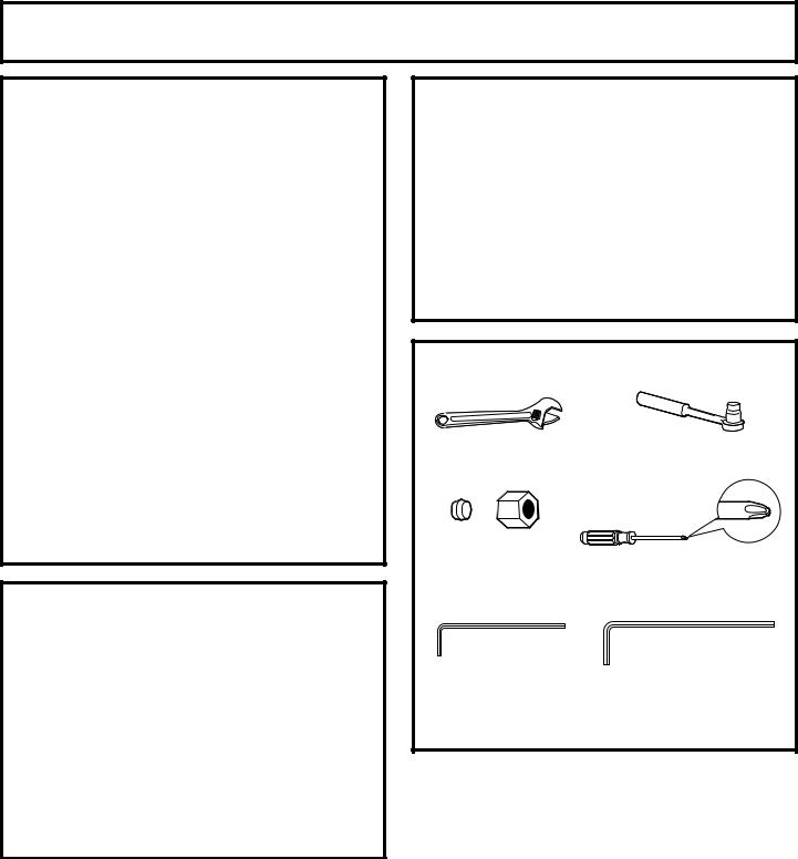
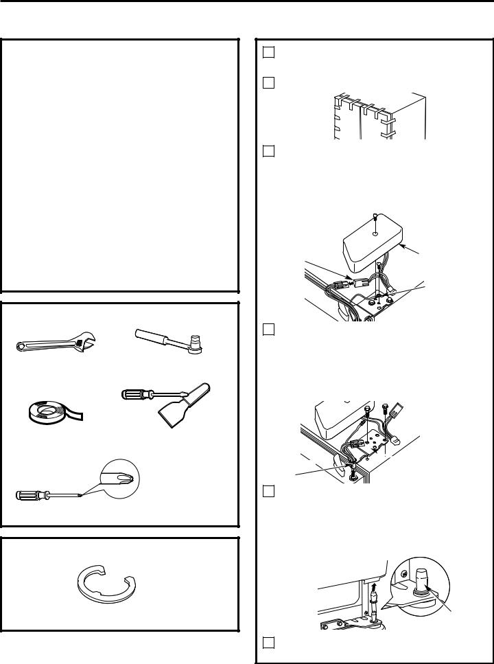
TOOLS YOU MAY NEED |
||
Adjustable Wrench |
3/8″ and 10 mm Socket |
|
Ratchet/Driver |
||
|
||
1/4″ Outer Diameter |
|
|
Compression Nut |
Phillips Head Screwdriver |
|
and Ferrule (sleeve) |
||
|
||
(icemaker models only) |
|
|
3/32″ Allen wrench |
1/4″ Allen wrench supplied |
|
supplied for use on |
||
for changing handle |
||
Stainless steel |
||
fasteners location |
||
refrigerator handles |
||
(on some models) |
||
(on some models) |
||
|
||
16
Installation Instructions
INSTALLING THE REFRIGERATOR
REFRIGERATOR LOCATION
•Do not install the refrigerator where the temperature will go below 60°F (16°C) because it will not run often enough to maintain proper temperatures.
•Do not install the refrigerator where the temperature will go above 100°F (37°C) because it will not perform properly.
•Install it on a floor strong enough to support it fully loaded.
CLEARANCES
Allow the following clearances for ease of installation, proper air circulation and plumbing and electrical connections.
Sides |
1/8″ (4 mm) |
Top |
1″ (25 mm) |
Back |
1″ (25 mm) |
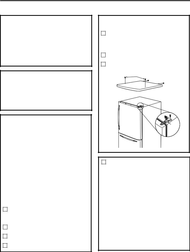
REMOVE TOP CAP (on some models)
•IMPORTANT NOTE: This refrigerator is 34-1/2″ deep.
Doors and passageways leading to the installation location must be at least 36″ wide in order to leave the doors and handles attached to the
refrigerator while transporting it into the installation location. If passageways are less than 36″, the refrigerator doors and handles can easily be scratched and damaged. The top cap and doors can be removed to allow the refrigerator to be safely moved indoors. Start with Step A.
•If it is not necessary to remove doors, skip Step A. Leave tape and all packaging on doors until the refrigerator is in the final location.
•SKID REMOVAL: Tilt refrigerator to each side to remove skid.
•NOTE: Use a padded hand truck to move this refrigerator. Place the refrigerator on the hand truck with a side against the truck. We strongly recommend that TWO PEOPLE move and complete this installation.
ALocate and remove the two Phillips head screws on the top of the refrigerator. Remove the two screws on each side at the rear of the top cap. Lift off and remove top cap.
BRemove the fresh-food door. Refer to Steps 1 through 3 of “Reversing the Door Swing” section.
CRemove the bottom freezer drawer. Refer to “Removing Freezer Drawer” section.
DMove refrigerator to the installation location.
REMOVE TOP CAP (cont.) (on some models)
REINSTALL DOORS, DRAWERS AND TOP CAP
ECarefully lower the door onto the center hinge. Reinstall top hinge. NOTE: Ensure the door is properly aligned to the case top to avoid readjustment of the door during top cap reinstallation.
FPlace cap over the top of the refrigerator. Reinstall the original screws in the top and back of the cap.
GReinstall the bottom freezer drawer. Refer to “Replacing the Freezer Drawer” section.
A.
Top Hinge |
B. |
1CONNECTING THE REFRIGERATOR TO THE HOUSE WATER LINE
(icemaker and dispenser models)
A cold water supply is required for automatic icemaker operation. If there is not a cold water supply, you will need to provide one. See
Installing the Water Line section.
NOTES:
•Before making the connection to the refrigerator, be sure the refrigerator power cord is not plugged into the wall outlet.
•If your refrigerator does not have a water filter, we recommend installing one if your water supply has sand or particles that could clog the screen of the refrigerator’s water valve. Install it in the water line near the refrigerator. If using GE SmartConnect™ Refrigerator Tubing Kit, you will need an additional tube (WX08X10002) to connect the filter. Do not cut plastic tube to install filter.
17

Installation Instructions
INSTALLING THE REFRIGERATOR (cont.)
1CONNECTING THE REFRIGERATOR TO THE HOUSE WATER LINE (cont.)
AIf you are using copper tubing, place a compression nut and ferrule (sleeve) onto the end of the tubing coming from the house cold water supply.
If you are using the GE SmartConnect™ tubing, the nuts are already assembled to the tubing.
BIf you are using copper tubing, insert the end of the tubing into the refrigerator
connection, at the back of the refrigerator, as far as possible. While holding the tubing, tighten the fitting.
If you are using GE SmartConnect™ tubing, insert the molded end of the tubing into the refrigerator connection, at the back of the refrigerator, and tighten the compression nut until it is hand tight. Then tighten one additional turn with a wrench. Overtightening may cause leaks.
CFasten the tubing into the clamp provided to hold it in position. You may need to pry open the clamp.
One of the illustrations below will look like the connection on your refrigerator.
Icemaker-Ready models
1/4″ |
Tubing |
|
Copper |
Clamp |
|
Tubing |
||
|
1/4″ Compression Nut
|
Ferrule |
|
|
(sleeve) |
|
SmartConnect™ |
Refrigerator |
|
Tubing |
||
Connection |
||
|
Icemaker-Installed Models
Refrigerator |
Ferrule |
|
(sleeve) |
||
Connection |
||
1/4″ Tubing |
||
SmartConnect™ |
|
|
Tubing |
|
|
1/4″ |
|
|
Compression |
|
|
Nut |
|
|
|
Tubing Clamp |
18
2 TURN ON THE WATER SUPPLY
(icemaker and dispenser models)
Turn the water on at the shutoff valve (house water supply) and check for any leaks.
3 PLUG IN THE REFRIGERATOR
On models with an icemaker, before plugging in the refrigerator, make sure the icemaker power switch is set to the O (off) position.
See the grounding information attached to the power cord.
4PUT THE REFRIGERATOR IN PLACE
Move the refrigerator to its final location.
Installation Instructions
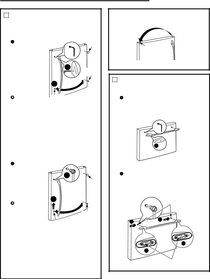
5REMOVE THE FRESH FOOD DOOR HANDLE
(For placement in the installation location or reversal of the handles – on some models)
Stainless steel (on some models): |
|
||
A REMOVING |
|
|
|
THE DOOR |
|
|
Badge |
HANDLE: Loosen |
|
|
|
the set screws |
|
|
|
with the 3/32″ |
|
|
|
Allen wrench |
|
|
|
and remove |
|
A |
Plug |
the handle. NOTE: |
|
|
|
|
|
Button |
|
For Double Door |
|
|
|
|
|
|
|
models follow the |
|
|
|
same procedure |
|
B |
|
on the opposite |
|
|
|
door. |
Mounting |
|
|
REVERSING THE |
|
||
DOOR HANDLE: |
Fasteners |
|
|
•Remove the |
|
(appearance may vary) |
|
handle mounting fasteners with a 1/4″ Allen |
|||
wrench and transfer |
handle mounting |
||
fasteners to the right side. |
|
||
•Remove and transfer the plug button and |
|||
logo badge to the |
|
side of the fresh food |
|
door. NOTE: Use a |
|
plastic edge to prevent |
|
damaging the door Remove any adhesive on |
|||
the door with a mild detergent. Remove the |
|||
paper covering on |
|
adhesive backing on |
|
the logo badge prior |
carefully attaching the |
||
badge to the door. |
|
|
|
Plastic handle (on some models): |
|
||
A REMOVING |
|
|
|
THE DOOR |
|
|
|
HANDLE: Slide |
|
B |
|
the handle up |
|
|
|
|
|
Badge |
|
on the handle |
|
|
|
mounting |
|
|
|
fasteners and |
|
|
|
remove the |
|
|
|
handle. |
A |
|
|
REVERSING THE |
|
|
|
DOOR HANDLE: |
|
|
|
•Remove the |
|
|
Plug |
handle |
|
|
Button |
mounting |
|
Mounting Fasteners |
|
fasteners with a |
|
(appearance may vary) |
|
3/8″ or 10 mm |
|
||
socket wrench and transfer the handle mounting fasteners to the right side.
•Remove and transfer the plug button and logo badge to the left side of the fresh food door. NOTE: Use a flat plastic edge to prevent damaging the door. Remove any adhesive on the door with a mild detergent. Remove the paper covering on the adhesive backing on the logo badge prior to carefully attaching the badge to the door.
After removing the handle: Move the small plug button from the top right side of the door top and insert it into the hole on the opposite side.
Small
 Plug
Plug
Button
(appearance may vary)
6REMOVE THE FREEZER DOOR HANDLE
Stainless steel handle:
ALoosen the set screws located on the underside of the handle with the 3/32″ Allen wrench and remove the handle.
NOTE: If the handle mounting fasteners need to be tightened or removed use a 1/4″ Allen wrench.
A 
Plastic handle:
ASlide the handle to the right on the handle mounting fasteners and remove the handle.
NOTE: If the handle mounting fasteners need to be tightened or removed use a 3/8″ or 10 mm socket wrench.
Mounting fasteners
A
A
A
A |
|
|
(appearance may vary) |
Slots on back |
|
of handle |
||
|
19

Installation Instructions
INSTALLING THE REFRIGERATOR (cont.)
7ATTACH THE FRESH FOOD DOOR HANDLE
Stainless steel handle:
AAttach the handle to the handle
mounting |
|
A |
Badge |
fasteners and |
|
||
tighten the set |
|
|
|
screws with a |
|
|
|
3/32″ Allen |
|
|
|
wrench. |
Mounting |
|
|
NOTE: For |
Fasteners |
|
|
Double Door |
|
|
|
models follow the |
|
|
|
same procedure |
Plug |
|
|
on the opposite |
|
Button |
|
door.
(appearance may vary)
Plastic handle:
AAttach the handle to the handle mounting fasteners by aligning the slots with the handle mounting fasteners.
 Slide it down until it is firmly locked into position.
A
Mounting
fasteners Slots on back of handle
A
8ATTACH THE FREEZER DOOR HANDLE
Stainless steel handle:
AAttach the handle firmly to the mounting
fasteners and tighten the set screws on the bottom of the handle with a 3/32″ Allen wrench.
A
(appearance may vary)
Plastic handle:
AAttach the handle to the mounting fasteners by aligning the slots with the mounting fasteners.
 Slide it to the left until it is firmly locked into position.
Mounting fasteners
A
A
Slots on back (appearance may vary) of handle
NOTE: A properly locked handle will be centered on the freezer.
(appearance may vary)
20
Installation Instructions
9 LEVEL THE REFRIGERATOR
The leveling legs have 3 purposes:
1)Leveling legs adjust so the door closes easily when opened about halfway.
(Front of the refrigerator should be 1/4″ [6 mm] higher than the rear of the refrigerator).
2)Leveling legs adjust so the refrigerator is firmly positioned on the floor and does not wobble.
3)Leveling legs serve as a stabilizing brake to hold the refrigerator securely in position during operation and cleaning.
ATurn the leveling legs clockwise to raise the refrigerator, counterclockwise to lower it.
 CAUTION: To avoid possible personal injury or property damage, the leveling legs must be firmly touching the floor.
BInstall the base grille by aligning the prongs on the back of the grille with the holes in the cabinet. Push forward until the grille snaps into place.
Freezer  Door (hinge) models only
10 SET THE CONTROLS
Set the controls to the recommended setting.
11REMOVE PACKAGING START ICEMAKER
(icemaker models)
A)Remove all tape, foam and protective packing from shelves and drawers.
B)Remove the tie downs from the freezer baskets.
C)Place half width basket onto drawer slides. See About the freezer section for instructions.
Set the icemaker power switch to the I (on) position. The icemaker will not begin to operate until it reaches its operating temperature of 15°F (–9°C) or below. It will then begin operation automatically. It will take 2–3 days to fill the ice bin.
Power switch
NOTE:
In lower water pressure conditions, the water valve may turn on up to 3 times to deliver enough water to the icemaker.
21
Installation Instructions
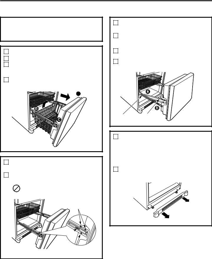
REMOVING THE FREEZER DRAWER (on some models)
The freezer drawer can be removed, if needed, to fit through tight areas.
Read these instructions completely and carefully.
1 REMOVE THE BASKET
AOpen the freezer drawer until it stops.
BThe freezer basket rests on a frame inside the freezer drawer. Lift the basket up at the back.
CLift the front up and lift the entire basket up and out of the drawer.
A
2REMOVE THE DRAWER FRONT FROM THE SLIDES
ARemove the Phillips head screw on each side of the railing.
DO NOT remove the hex head screws from the rail assemblies.
DO NOT remove hex head screws
Phillips Screw
DO NOT remove hex head screws
2REMOVE THE DRAWER FRONT FROM THE SLIDES (cont.)
BLift up on both sides of the freezer drawer handle to separate the drawer railings from the rail assemblies.
CSet the drawer front on a nonscratching surface.
DPush the rail assemblies back into locking position.
Rail
Assembly Drawer
Assembly
3 REMOVE THE BASE GRILLE
(if needed)
If, after removing the freezer drawer and refrigerator door, the refrigerator will still not fit through a doorway, the base grille can be removed.
ARemove the base grille by grasping it at the bottom and pulling it straight out.
22

Installation Instructions
REPLACING THE FREEZER DRAWER (on some models)
Two people may be required to complete this procedure.
1ATTACH AND SECURE THE DRAWER FRONT TO THE SLIDES
APull out the rail assemblies to the full length on each side of the cabinet.
BLocate the slots on the inside of the rail assemblies near the back.
Slot
Rail assembly
CInsert the hooks at the back of the drawer railings into the slots on the rail assemblies.
DLower the front of the drawer, making
sure |
the railings |
fit into |
assemblies. |
1ATTACH AND SECURE THE DRAWER FRONT TO THE SLIDES
(cont.)
EReplace the Phillips head screws on both rail assemblies.
Phillips
Screw
2 REPLACE THE FREEZER BASKET
Replace the lower freezer basket by lowering it into the frame.
Hook
Slot

 Tab
Tab
23

Installation Instructions
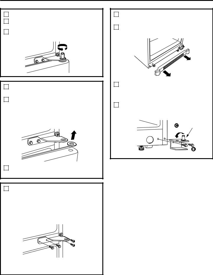
REVERSING THE DOOR SWING (Single Door Refrigerator Models only)
IMPORTANT NOTES |
1 |
REMOVE THE |
|
||
When reversing the door swing: |
|
REFRIGERATOR DOOR |
|
|
Tape the door shut with masking tape. |
NOTE: Door swing is not reversible on some |
A |
|
|
||
stainless steel models. |
|
|
•Read the instructions all the way through before starting.
•Handle parts carefully to avoid scratching paint.
• Set screws down by their related parts to avoid using them in the wrong places.
• Provide a non-scratching work surface for the doors.
IMPORTANT: Once you begin, do not move |
|
|
|
|
the cabinet until door-swing reversal is |
|
|
|
|
completed. |
|
Remove the hinge cover on top of the |
||
B |
||||
|
||||
These instructions are for changing the |
|
refrigerator door by squeezing it and |
||
hinges from the right side to the left side—if |
|
pulling it up. |
||
you ever want to change the hinges back to |
|
Using a 3/8″ or 10 mm socket |
||
C |
||||
the right side, follow these same instructions |
|
ratchet/driver, remove the bolts securing |
||
and reverse all references to left and right. |
|
the top hinge to the cabinet. Then lift the |
||
• Once door swing is finalized, ensure |
|
hinge straight up to free the hinge pin |
||
the logo badge is properly aligned and |
|
from the socket in the top of the door. |
||
permanently secured to the door by |
|
|
|
|
removing the adhesive cover on the back |
|
|
|
|
side. NOTE: If necessary call Customer |
|
|
|
|
|
|
Hinge Cover |
||
Service for a replacement badge. |
|
|
||
Unplug the refrigerator from its electrical outlet.
Empty all door shelves, including the dairy compartment.
|
|
Top Hinge |
TOOLS YOU WILL NEED |
|
|
|
D |
Remove the tape and tilt the door away |
|
|
from the cabinet. Lift the door off the |
|
3/8″ and 10 mm Socket |
center hinge pin. Ensure that the white |
Adjustable Wrench |
hinge pin thimble remains on the hinge pin |
|
|
Ratchet/Driver |
or inside door hinge pin hole located in the |
|
|
|
|
|
bottom of the door. |
Masking Tape |
Putty Knife or |
|
|
Thin-blade Screwdriver |
|
|
E |
Set the door on a non-scratching surface |
Phillips Screwdriver |
|
with the inside up. |
|
|
|
|
24 |
|
Installation Instructions
2 REMOVE THE CENTER HINGE PIN
AOn models with a freezer door, tape the door shut with masking tape.
BUsing an adjustable wrench, remove the center hinge pin.
3 REMOVE THE FREEZER DOOR
(freezer door models)
ARemove the tape and tilt the door away from the cabinet. Lift the door off the bottom hinge pin.
NOTE: There is a plastic washer between the hinge and the top of the freezer door. Do not lose.
BSet the door on a non-scratching surface with the inside up.
4 REMOVE CENTER HINGE
Using a 3/8″ or 10 mm socket ratchet/driver and Phillips head screwdriver, remove the bolts and screws securing the center hinge to the cabinet. Set hinge, bolts, screws, washer (on freezer door models) and hinge pin aside.
On models with a freezer drawer, skip to Step 7.
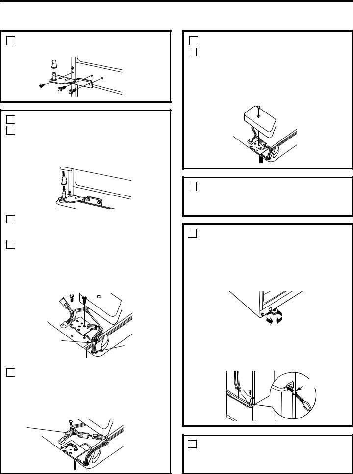
5TRANSFER BOTTOM HINGE BRACKET (freezer door models)
ARemove the base grille by grasping it at the bottom and pulling it straight out.
BUsing a 3/8″ or 10 mm socket ratchet/driver, remove the screws securing the bottom hinge bracket to the cabinet.
CUsing an adjustable wrench, remove the hinge pin and washer(s) from the right side of the bracket and install on the left.
Washer(s)
25

Installation Instructions
REVERSING THE DOOR SWING (cont.)
5TRANSFER BOTTOM HINGE BRACKET (freezer door models, cont.)
DInstall the bottom hinge bracket on the left side of the cabinet.
EReplace the base grille by aligning the prongs on the back of the grille with the holes in the cabinet. Push forward until the grille snaps into place.
6 TRANSFER FREEZER DOOR STOP
(freezer door models)
ARemove the door stop on right side of the bottom of the freezer door by removing the two screws.
BMove the plastic hinge hole thimble to the opposite hole.
CInstall the door stop on the left side.
7 INSTALL CENTER HINGE
ATransfer the plug button and screws in the hinge holes on the left side to the right side.
B Install the center hinge on the left side.
8 HANG THE FREEZER DOOR
(freezer door models)
Lower the freezer door onto the bottom hinge pin, then shut the door, making sure to align the door with the cabinet. Make sure the gasket on the door is flush against the cabinet.
A
Bottom of Freezer Door |
|
Bottom of Freezer Door |
(Right Side) |
|
(Left Side) |
|
|
|
26

Installation Instructions
9 INSTALL CENTER HINGE PIN
AInstall the center hinge pin.
NOTE: On models with a freezer door, be sure to put the washer between the top of the freezer door and the bottom of the center hinge.
Freezer Door Models |
Freezer Drawer Models |
10TRANSFER REFRIGERATOR DOOR STOP
ARemove the door stop on right side of the bottom of the refrigerator door by removing the two screws.
BMove the plastic hinge hole thimble to the opposite hole.
CInstall the door stop on the left side, making sure to line up the screw holes in the door stop with the holes in the bottom of the door.
A
Bottom of |
|
Bottom of |
Refrigerator Door |
|
Refrigerator Door |
(Right Side) |
|
(Left Side) |
|
|
|
11TRANSFER REFRIGERATOR DOOR HANDLE TO RIGHT
Refer to Remove the Fresh Food Door Handle and Attach the Fresh Food Door Handle sections for instructions.
12 REHANG REFRIGERATOR DOOR
ALower the refrigerator door onto the center hinge pin. Ensure that the white hinge pin thimble is on the center hinge pin or inside door hinge pin hole located in the bottom of the door.
BInsert the top hinge pin into the hinge hole on top of the refrigerator door. Make sure the door is aligned with the cabinet. Attach the hinge to the top of the cabinet loosely with the bolts.
CMake sure the gasket on the door is flush against the cabinet and is not folded. Support the door on the handle side and make sure the door is straight and the gap between the doors is even across the front. While holding the door in place, tighten the top hinge bolts. Replace the hinge cover.
27
Installation Instructions
REMOVING THE DOORS (Double Door Refrigerator Models only)
IMPORTANT NOTES
NOTE: Door swing is not reversible.
•Read the instructions all the way through before starting.
•Handle parts carefully to avoid scratching paint.
•Set screws down by their related parts to avoid using them in the wrong places.
•Provide a non-scratching work surface for the doors.
IMPORTANT: Once you begin, do not move the cabinet.
These instructions are for removing the doors.
Unplug the refrigerator from its electrical outlet.
Empty all door shelves, including the dairy compartment.
TOOLS YOU WILL NEED |
|
Adjustable Wrench |
3/8″ and 10 mm Socket |
|
Ratchet/Driver |
Masking Tape |
Putty Knife or |
|
Thin-blade Screwdriver |
Phillips Screwdriver |
|
PARTS INCLUDED
C Spacer (on some models)
1REMOVE THE REFRIGERATOR DOORS
ATape the doors shut with masking tape.
BRemove the screw securing each hinge cover, lift the hinge cover and place to the side on top of the refrigerator.
Carefully disconnect the wire connector and remove the screw securing the ground wire.
Wire |
Hinge Cover |
|
Connector |
||
|
||
|
Ground Wire |
|
|
(appearance may vary) |
CUsing a 3/8″ or 10 mm socket ratchet/driver, remove the bolts securing the top hinge to the cabinet. Then lift the hinge straight up to free the hinge pin from the hinge pin hole in the top of the door. Carefully remove the wires from the hinge pin through the slot.
Hinge Pin
Slot
 Top Hinge
(appearance may vary)
DRemove the tape and tilt the door away from the cabinet. Lift the door off the center hinge pin. Ensure that the white hinge pin thimble remains on the center hinge pin or inside door hinge pin hole located in the bottom of the door.
Hinge Pin
Thimble
ESet the door on a non-scratching surface with the inside up.
28

Installation Instructions
2 REMOVE CENTER HINGE
Using a 3/8″ or 10 mm socket ratchet/driver and Phillips head screwdriver, remove the bolts and screw securing the center hinge to the cabinet. Set hinge, bolts, and screw aside.
3 REMOVE OPPOSITE DOOR
Follow the same procedure on the opposite door.
4 REMOVE FREEZER DRAWER
Refer to the Removing the Freezer Drawer section for instructions.
29
Installation Instructions
REPLACING THE DOORS (Double Door Refrigerator Models only)
1 INSTALL CENTER HINGE
Install the center hinge on each side.
2 REHANG REFRIGERATOR DOORS
ALower the refrigerator door onto the center hinge pin. Ensure that the white hinge pin thimble is on the center hinge pin or inside door hinge pin hole located in the bottom of the door.
Hinge Pin 

Thimble
BSecurely tape the door shut with masking tape or have a second person support the door.
CRoute wires through top hinge pin slot. Insert the top hinge pin into the hinge hole on top of the refrigerator door. Make sure the door is aligned with the cabinet and opposite door. Attach the hinge to the top of the cabinet loosely with the bolts.
Top Hinge |
Top Hinge |
|
Pin |
||
Pin Slot |
||
(appearance may vary) |
||
|
DReconnect the wire connector and reconnect the ground wire using the screw removed earlier. Ensure that the wire connector is fully engaged.
IMPORTANT: The ground wire must be reinstalled to ensure a proper ground.
Wire
Connector
Ground Wire
2 REHANG REFRIGERATOR DOORS (CONT.)
EMake sure the gasket on the door is
flush against the cabinet and is not folded. Make sure the door is straight and the gap between the doors is even across the front. While holding the aligned door in place, tighten the top hinge bolts. Replace the hinge cover and screw.
Hinge Cover 
Top Hinge Bolts


(appearance may vary)
3 REPLACE OPPOSITE DOOR
Follow the same procedure on the opposite door.
4 ALIGN DOUBLE DOORS
If the top of the doors are uneven, first try to raise the lowest door by turning the leveling leg on the same side as the door until the doors are even. If the unit rocks, re-adjust the leveling legs to the extent that the unit is stable.
If the doors remain uneven, use a C spacer to align the doors. While lifting the door on the hinge side with one hand, insert a C spacer with pliers. Continue to add C spacers until the doors are even.
C Spacer
5 REPLACE FREEZER DRAWER
Refer to the Replacing the Freezer Drawer section for instructions.
30
 Loading...