


g
GEI M1010-A
GE Energy
Motor Installation
And Maintenance Instructions
Vertical AC Small Industrial Motors
NEMA 182 to 5011 Frame
NEMA Type P Base, Solid Shaft, TEFC Normal Thrust and Aeration Pump Motors
© Copyright 2011 General Electric Company |
2011/6/13 |

|
|
GEI M1010-A |
Table of Contents |
|
|
I. |
General Information................................................................................................................................................. |
1 |
|
A. How to Properly Use this Instruction Manual ................................................................................. |
1 |
|
B. Safety Symbols ............................................................................................................................................. |
1 |
|
C. Safe Motor Operation Information ...................................................................................................... |
2 |
|
D. Description of Labels and Nameplates ............................................................................................. |
3 |
|
E. Model and Serial Numbers ...................................................................................................................... |
3 |
|
F. Relevant Industry Standards .................................................................................................................. |
3 |
II. |
Receiving ....................................................................................................................................................................... |
3 |
|
A. Unpacking....................................................................................................................................................... |
3 |
|
B. Temporary Storage..................................................................................................................................... |
4 |
|
C. Extended Storage ........................................................................................................................................ |
4 |
|
D. Handling .......................................................................................................................................................... |
4 |
III. |
Installation.................................................................................................................................................................... |
4 |
|
A. Location ........................................................................................................................................................... |
4 |
|
B. Mounting.......................................................................................................................................................... |
5 |
|
C. Power Supply and Connections ............................................................................................................ |
6 |
IV. |
Operation…………………………………………… .................................................................................................................... |
6 |
|
A. Steps Prior to Starting................................................................................................................................ |
6 |
|
B. Initial Start....................................................................................................................................................... |
7 |
|
C. Jogging and Repeated Starts................................................................................................................. |
8 |
V. |
Maintenance................................................................................................................................................................ |
8 |
|
A. General ............................................................................................................................................................. |
8 |
|
B. General Cleanliness .................................................................................................................................... |
8 |
|
C. Division 1 Explosion Proof Motors........................................................................................................ |
8 |
|
D. Insulation and Windings .......................................................................................................................... |
8 |
|
E. Vacuum and Compressed Air Cleaning ............................................................................................. |
9 |
|
F. Cleaning with Water and Detergent.................................................................................................... |
9 |
|
G. Anti-Friction Bearings and Lubrication.............................................................................................. |
9 |
VI. |
Operational Difficulties ......................................................................................................................................... |
11 |
VII. |
Failure ........................................................................................................................................................................... |
12 |
VIII. |
Repair............................................................................................................................................................................ |
12 |
IX. |
Renewal Parts ........................................................................................................................................................... |
12 |
X. |
Tightening Torque for SAE Hardware............................................................................................................. |
13 |
XI. |
Motor Lubrication Guide....................................................................................................................................... |
14 |
© Copyright 2011 General Electric Company
GEI M1010-A
I. GENERAL INFORMATION
A. How to Properly Use this Instruction Manual
This installation and maintenance manual has been written to assist the user with proper procedures when handling, installing, operating and maintaining the equipment. All of the safety warnings and instructions in this book must be followed to prevent injury to personnel.
This manual must be kept for future reference during installation, operation and maintenance.
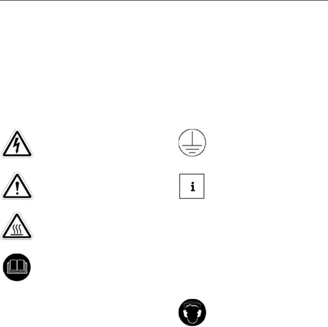
B. Safety Symbols
Below is a safety symbol table that identifies the safety symbols that appear in this manual and on the motors.
The use of a lightning bolt within an arrowhead symbol, enclosed in a yellow triangle warns of dangerous electrical voltage that could cause an electric shock to a person.
The use of an exclamation point within a yellow triangle indicates to the user that important installation, operating and maintenance instructions must be followed.
The use of wavy lines, enclosed in a yellow triangle, indicates that the motor can be hot and should not be touched without taking proper precautions.
This symbol instructs one to read the manufacturer’s instruction manual before installation, operation and maintenance.
This symbol identifies a terminal, which is intended for connection to an external grounding conductor for protection against electric shock in case of a fault.
The use of a small case “i” enclosed in a square indicates a general note.
Indicates a procedure or condition that, WARNING: if not strictly observed, could result in
personal injuries or death.
Indicates a procedure or condition that, CAUTION: if not strictly observed, could result in
minor injuries to personnel.
This symbol indicates the need to wear hearing protection.
© Copyright 2011 General Electric Company |
1 |
GEI M1010-A
C. Safe Motor Operation Information
WARNINGS: High voltage and rotating parts can cause serious or fatal injuries. Qualified personnel should perform installation, operation and maintenance of electrical machinery. For equipment covered by this instruction book, it is important to observe safety precautions to protect
personnel from possible injury. Be sure to keep the installation and maintenance information for future reference. All warnings and cautions must be followed.
Installation
•Avoid contact with energized circuits and rotating parts.
•Avoid bypassing or rendering inoperative any safeguards or protective devices.
•Avoid use of automatic-reset thermal protection where unexpected starting of equipment might be hazardous to personnel.
•Avoid contact with capacitors until safe discharge procedures have been followed.
•Be sure the motor shaft key is captive before the motor is energized.
•Avoid long exposure in close proximity to machinery with high noise levels.
•When the motor is coupled to equipment, ensure that system vibrations are within acceptable limit (per ISO 10816- 1) to avoid failure of the motor.
•Use proper protective gear, care and procedures when handling, lifting, installing, operating and maintaining the motor.
•If eyebolts are used for lifting motors, they must be securely tightened, and the direction of the lift must not exceed a 15° angle from the shank of the eyebolt. Do not use eyebolts in an ambient below 0°F. At temperatures below 0° F, the eyebolt could fail resulting in injury to personnel and/or damage to equipment. Drop-forged eyebolts per American Society of Testing Materials A489 or equivalent must be used.
•Do not use the motor shaft as a means for lifting.
•Do not lift both the motor and driven equipment with the motor lifting means.
•Do not stand on or place objects on the motor.
Maintenance
Safe maintenance practices performed by qualified personnel are imperative. Before starting maintenance procedures, be positive that:
•Equipment connected to the shaft will not cause mechanical rotation.
•Main motor windings and all accessory devices associated with the work area are disconnected from electrical power sources.
•The motor has been given time to cool.
Failure to properly ground the frame of the motor can cause serious injury to personnel. Grounding should be in accordance with National and local Standards and consistent with sound practice.
These instructions do not purport to cover all the details in motors nor to provide for every possible contingency to be met in connection with installation, operation or maintenance. Should further information be desired or should particular problems arise which are not covered sufficiently for the purchaser’s purposes, the matter should be referred to the General Electric Company.
This document contains proprietary information of General Electric Company, USA and is furnished to its customer solely to assist that customer in the installation, testing, operating and/or maintenance of the equipment described. This document shall not be reproduced in whole or in part, nor shall its contents be disclosed to any third party without the written approval of GE Energy.
© Copyright 2011 General Electric Company |
2 |

GEI M1010-A
D. Description of Labels and Nameplates
Motor rating and identification data are furnished on labels and nameplates. Packing nameplates provide a permanent record of motor characteristics, plant identification and date of manufacture. Below is an example of a label that is attached to the shipping package.
MOD – GE model number KW = Motor power rating
RPM = Motor speed at full load
VOL – Motor voltage ENCL = Enclosure code FR = Frame size
MASS = Motor mass
Figure 1: Packing Label
E. Model and Serial Numbers
As discussed in section D, every motor that is manufactured by GE Energy has a model and serial number, which are permanently marked on the motor nameplate. When contacting a GE Energy Service Shop or representative, please provide to the model and serial numbers.
Data and information regarding an individual motor model can be obtained from the Data Pack for the motor or through EliteNet or by contacting your local GE Energy representative.
F.Relevant Standards
1.Motors shipped with this installation instruction have been designed and built to the latest revision of the following standards:
a.NEMA MG-1
2.Motors that have the IECEx designation have also been designed to meet the requirements of the following standards:
a.IEC and/or BS/EN 60079-0
b.IEC and/or BS/EN 60079-15
3.Motors with the CE Mark have also been designed to meet the requirements of the following EU directives:
a.Machinery safety
b.Low Voltage
c.Electromagnetic Compatibility
d.Conformity Assessment
II.RECEIVING
Each shipment should be carefully inspected upon arrival. Motor rating and identification data are furnished on a packing label for verification purposes. Any damage should be reported promptly to the carrier and a claim filed. The nearest GE Energy sales office may provide additional guidance.
A. Unpacking
If the motor has been exposed to low temperatures, unpack it only after it has reached the temperature of the room in which it will be unpacked. Otherwise the motor windings will be exposed to condensing moisture.
© Copyright 2011 General Electric Company |
3 |

GEI M1010-A
B. Temporary Storage (Up to 6 Months)
If the motor will not be put into service immediately, certain precautions should be taken to protect the motor while in storage. It is recommended the motor be placed under cover in a clean, dry location.
During storage, windings should be protected from excessive moisture by some safe and reliable method of heating, such as space heaters, to keep the temperature of windings above the temperature of the surrounding air. It is recommended the motor in storage be inspected at periodic intervals, the windings meggered and a log kept of pertinent data. (Refer to the OPERATION section.) Any significant drop in insulation resistance should be investigated.
Precautions are taken by the factory to guard against corrosion. The machined parts are coated to prevent rust during shipment. If the equipment is to be stored, examine the machined parts carefully for rust and moisture and recoat where necessary.
The bearings of grease-lubricated motors are greased at the factory with the grease cavity approximately 50% full. Rotate the shaft of all grease-lubricated motors 10-20 revolutions at two-month intervals.
If the purchaser has specified the machine be packaged for long-term storage, the foregoing recommendations do not apply and the packing should be left intact during the period of storage.
C. Extended Storage (Longer than 6 months)
In the event the motor is to be stored longer than six months, please refer to GE instruction manual GEK-97427.
D. Handling
WARNING: Lifting lugs on the motor are designed for handling only the motor. They are not to be used to lift the motor plus additional equipment such as pumps, compressors or other driven equipment. In the case of assemblies on a common base, lugs or eyebolts provided on the motor are not to be used to
lift the assembly and base. The assembly should be lifted by a sling around the base or by other lifting means provided on the base. In the case of unbalanced loads (such as couplings or other attachments), additional slings or other effective means should be used to prevent tipping.
III. Installation
WARNING: Installation should be in accordance with the ‘USA-National Electric Code’ or ‘BS/EN 60204- 1’ and ‘BS/EN 60204-11’ and consistent with sound National and local practices. Coupling, belt and chain guards should be installed as needed to protect against accidental contact with moving parts.
Motors accessible to personnel should be further guarded by screening, guard rails, etc., to prevent them from coming in contact with the equipment.
A. Location
Install the motor in a well-ventilated area. Make sure there is a minimum clearance of one foot around the motor to allow normal flow of air.
1.Drip-proof motors are intended to be used in a well-ventilated place reasonably free of dirt and moisture.
2.General Purpose enclosed motors can be used where they are exposed to dirt, moisture, and most outdoor conditions.
3.Severe-duty enclosed motors can be used in highly corrosive or excessively moist areas.
© Copyright 2011 General Electric Company |
4 |
 Loading...