


GFDN240GL0WW
GE GFDN240GL0WW, GFDN245GL0MS, GFDN245GL1BB, GFDN245GL1MG, GFDN245GL1MS Installation Guide
...
Installation
Instructions
Questions on Installation? Call: 1-800-GECARES (US)or 1-800-561-3344 (Canada)
BEFORE YOU BEGIN
Readthese instructions
completely and carefully.
•IMPORTANT- save these
instructions for local inspector's
use.
•IMPORTANT- Observe all
governing codes and ordinances.
• Note to Installer - Be sure to
leave these instructions with the
customer.
• Note to Customer - Keep
these instructions with your
Useand Cure Book for future
reference.
• Before the old dryer is removed
from service or discarded,
remove the dryer door.
• Service information and the
wiring diagram are located in
the control console.
• Do not allow children on or in
the appliance. Closesupervision
of children is necessary when
the appliance is used near
children.
• Install the dryer where the
temperature isabove 50°F for
satisfactory operation of the
dryer control system.
GasDryer l@
20 ®
or Visit our Web site at: www.GEAppliances.com (US)
-&WARNING RISK OF FIRE
•To reduce the risk of severe injury or death, follow all installation instructions.
• Clothes dryer installation must be performed by a qualified installer.
• Install the clothes dryer according to these instructions and in accordance with local
codes.
• California Safe Drinking Water and Toxic Enforcement Act
This act requires the governor of California to publish a list of substances known to the
state to cause cancer, birth defects or other reproductive harm and requires businesses
to warn customers of potential exposure to such substances. Gas appliances can
cause minor exposure to four of these substances, namely benzene, carbon monoxide,
formaldehyde and soot, caused primarily by the incomplete combustion of natural gas
or LPfuels. Properly adjusted dryers will minimize incomplete combustion. Exposure to
these substances can be minimized further by properly venting the dryer to the outdoors.
• This dryer must be exhausted to the outdoors.
• Use only rigid metal 4" diameter ductwork inside the dryer cabinet and use only UL
approved transition ducting between the dryer and the home duct.
• DONOTinstall a clothes dryer with flexible plastic ducting materials. If flexible metal
(semirigid or foil-type) duct is installed, it must be ULlisted and installed inaccordance
with the instructions found in "Connecting The Dryer To House Vent" on page 5 of this
manual. Flexible venting materials are known to collapse, be easily crushed, and trap
lint. Theseconditions will obstruct dryer airflow and increase the risk of fire.
• Do not install or store this appliance in any location where it could be exposed to
water and or weather.
• Savethese instructions. (Installers: Be sure to leave these instructions with the
customer).
IN THE COMMONWEALTH OF MASSACHUSETTS
• This product must be installed by a licensed plumber or gas fitter.
• When using ball-type gas shut-off valves, they shall bethe T-handle type.
• A flexible gas connector, when used, most not exceed 3 feet.
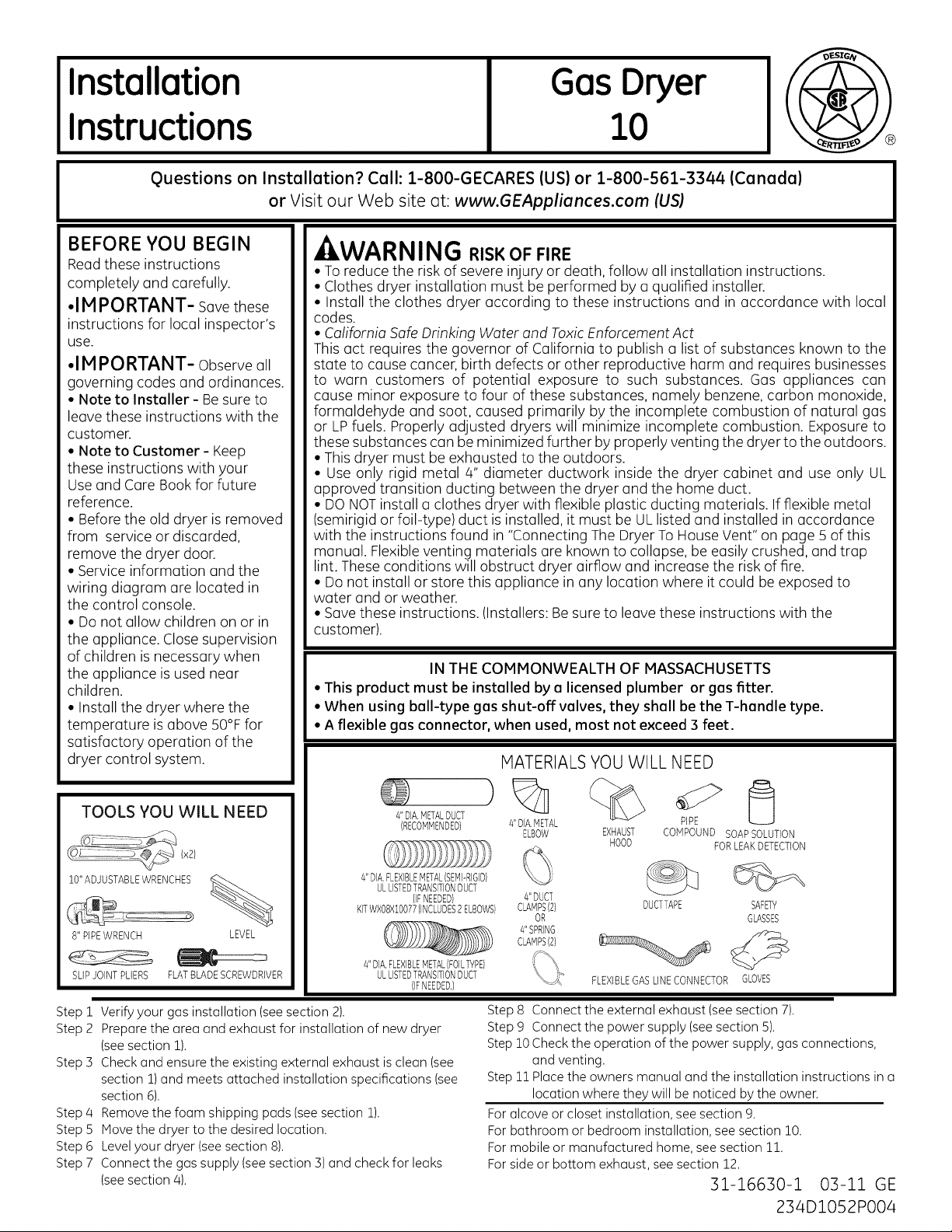
MATERIALSYOU WILL NEED
TOOLS YOU WILL NEED
10"ADJUSTABLEWRENCHES
8" PIPEWRENCH LEVEL
SLIPJOINTPLIERS FLATBLADESCREWDRIVER
Step 1
Verify your gas installation (see section 2).
Prepare the area and exhaust for installation of new dryer
Step 2
(seesection 1).
Step 5
Check and ensure the existing external exhaust is clean (see
section 1)and meets attached installation specifications (see
section 6).
Remove the foam shipping pads (see section 1).
Step 4
Step 5
Move the dryer to the desired location.
Step 6
Level your dryer (seesection 8).
Step 7
Connect the gas supply (seesection 3) and check for leaks
(seesection 4).
)
4"DIA,METALDUCT
(RECOMMENDED}
4"DIA,FLEXIBLEMETAL(SEMI-RIGID}
ULLISTEDTRANSITIONDUCT
KITWXO8X10077(INCLUDES2ELBOWS}
4"DIA,FLEXIBLEMETAL(FOILTYPE}
(IFNEEDED}
ULLISTEDTRANSITIONDUCT
(IFNEEDED.}
Step8 Connectthe externalexhaust(seesection7).
Step9 Connectthe powersupply(seesection5).
Step10Checkthe operationof the powersupply,gasconnections,
Step11Placethe ownersmanualandthe installationinstructionsina
Foralcoveor closet installation,see section9.
Forbathroomor bedroominstallation,seesection10.
Formobileor manufacturedhome,seesection 11.
Forsideor bottom exhaust,seesection12.
4"DIA,METAL
ELBOW EXHAUST
4"DUCT
CLAMPS(2}
OR
4"SPRING
CLAMPS(2}
FLEXIBLEGASLINECONNECTOR GLOVES
HOOD
PIPE
CONPOUND SOAPSOLUTION
FORLEAKDETECTION
DUCTTAPE SAFETY
GLASSES
and venting.
locationwheretheywillbe noticedbythe owner.
31-16630-1 03-11 GE
234D1052P004
Installation Instructions
Minimum Clearance Other Than Alcove or Closet Installation
Minimum clearance to combustible surfaces and for air opening are: 0 in. clearance both sides, 1 in. front 3 in. rear.
Consideration must be given to provide adequate clearance for installation and service.
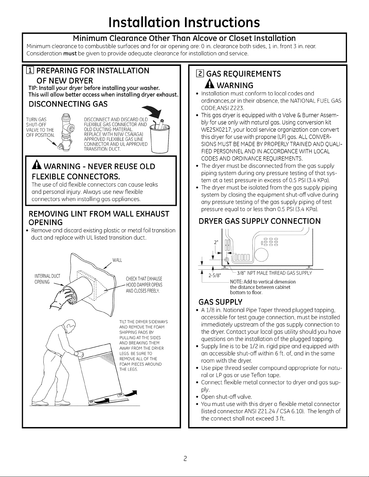
m PREPARING FOR INSTALLATION
OF NEW DRYER
TIP:Install your dryer before installing your washer.
This will allow better access when installing dryer exhaust.
DISCONNECTING GAS
TURN GAS _ DISCONNECT AND DISCARD OLu_. _
SHUT-OFF IF:;_ FLEXIBLEGAS CONNECTOR AND _-h_-__,--_
VALVETOTHE _t_ _ OLD DUCTING MATERIAL
OFF POSITION._ REPLACEWITH NEW CSA(AGA)
APPROVED FLEXIBLEGAS LINE
CONNECTOR AND UL APPROVED
TRANSITIONDUCT.
A
WARNING - NEVER REUSE OLD
FLEXIBLE CONNECTORS.
The use of old flexible connectors can cause leaks
and personal injury. Always use new flexible
connectors when installing gas appliances.
REMOVING LINT FROM WALL EXHAUST
OPENING
• Removeand discard existing plastic or metal foil transition
duct and replace with ULlisted transition duct.
Izl GAS REQUIREMENTS
-_ WARNING
• Installation must conform to local codes and
ordinances,or intheir absence, the NATIONALFUELGAS
CODE,ANSIZ223.
• This gas dryer is equipped with o Valve & Burner Assem-
blyfor use only with natural gas. Usingconversion kit
WE25X0217,your local service organization con convert
this dryer for usewith propane (LP)gas. ALLCONVER-
SIONSMUSTBEMADEBYPROPERLYTRAINEDANDQUALI-
FIEDPERSONNELAND IN ACCORDANCEWITHLOCAL
CODESANDORDINANCEREQUIREMENTS.
• The dryer must be disconnected from the gas supply
piping system during any pressure testing of that sys-
tem at a test pressure in excess of 0.5 PSI(3.4 KPa).
• The dryer must be isolated from the gas supply piping
system by closing the equipment shut-off valve during
any pressure testing of the gas supply piping of test
pressure equal to or less than 0.5 PSI(3.4 KPa).
DRYER GAS SUPPLY CONNECTION
J#
WALL
INTERNALDUCT
OPENING ODDAMPEROPENS
CHECKTHATEXHAUSE
ANDCLOSESFREELY.
TILTTHE DRYERSIDEWAYS
AND REMOVETHE FOAM
SHIPPING PADS BY
PULLING ATTHE SIDES
AND BREAKING THEM
AWAY FROM THE DRYER
LEGS, BE SURE TO
REMOVEALL OF THE
FOAM PIECESAROUND
THE LEGS,
3/8" NPT MALE THREADGAS SUPPLY
NOTE:Add to vertical dimension
the distance between cabinet
bottom to floor.
GAS SUPPLY
• A 1/8 in. National PipeTaper thread plugged tapping,
accessible for test gauge connection, must be installed
immediately upstream of the gas supply connection to
the dryer. Contact your local gas utility should you have
questions on the installation of the plugged tapping.
• Supply line is to be 1/2 in. rigid pipe and equipped with
an accessible shut-off within 6 ft. of, and in the same
room with the dryer.
• Use pipe thread sealer compound appropriate for natu-
ral or LPgas or use Teflon tape.
• Connect flexible metal connector to dryer and gas sup-
ply.
• Open shut-off valve.
• You must use with this dryer a flexible metal connector
(listed connector ANSIZ21.24 / CSA6.10). The length of
the connect shall not exceed 3 ft.
2
Installation Instructions
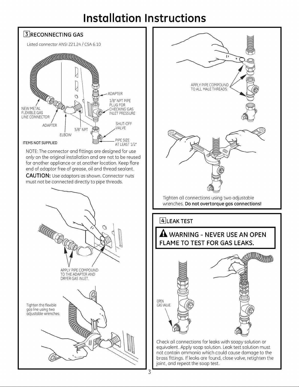
F3-IRECON NECTING GAS
Listed connector ANSI Z2!.24 / CSA 6.!0
1/8" NPTPIPE
PLUGFOR
NEWMETAL GAS
FLEXIBLEGAS INLETPRESSURE
LINECONNECTOR
ADAPTER SHUT-OFF
3/8" NPT VALVE
ELBOW
__PIPESIZE
ITEMSNOT SUPPLIED AT LEASTi/2"
NOTE: The connector and fittings are designed for use
only on the original installation and ore not to be reused
for another appliance or at another locution. Keep flare
end of adaptor free of grease, oil and thread sealant.
CAUTION: Use adaptors ms shown. Connector nuts
must not be connected directly to pipe threads.
APPLYPIPECOMPOUND
TOALL rVlALETHREADS.
©
Tighten the flexible
gas line using two
adjustable wrenches.
\
APPLYPIPECOMPOUND
TOTHE ADAPTERAND
DRYERGASINLET.
Tighten all connections using two adjustable
wrenches. Do not overtorque gas connections!
r4-]LEA K TEST
-_ WARNING- NEVER USE AN OPEN
FLAME TO TEST FOR GAS LEAKS.
GASVALVE.
OPEN
Check all connections for leaks with soapy solution or
equivalent. Apply soap solution. Leak test solution must
not contain (]mmonia which could cause damage to the
brass fittings. If leaks (]re found, close valve, retighten the
joint, and repeat the soup test.
Installation Instructions
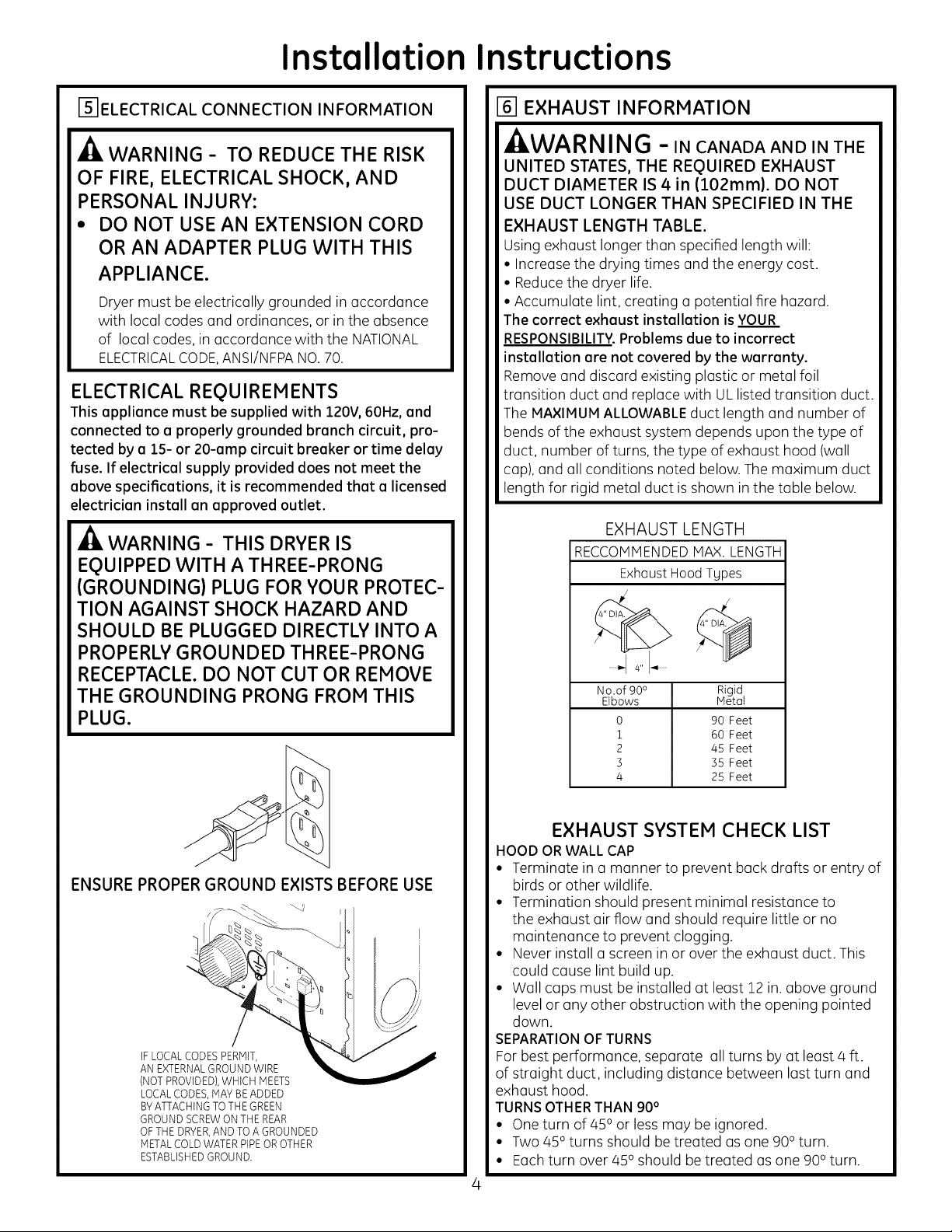
F5]ELECTRICAL CONNECTION INFORMATION
A
WARNING- TO REDUCE THE RISK
OF FIRE, ELECTRICAL SHOCK, AND
PERSONAL INJURY:
• DO NOT USE AN EXTENSION CORD
OR AN ADAPTER PLUG WITH THIS
APPLIANCE.
Dryer must be electrically grounded in accordance
with local codes and ordinances, or in the absence
of local codes, in accordance with the NATIONAL
ELECTRICALCODE,ANSI/NFPANO.70.
ELECTRICAL REQUIREMENTS
This appliance must be supplied with 120V,60Hz, end
connected to e properly grounded branch circuit, pro-
tected by e 15- or 20-amp circuit breaker or time delay
fuse. If electrical supply provided does not meet the
above specifications, it is recommended that a licensed
electrician install an approved outlet.
WARNING - THIS DRYER IS
EQUIPPED WITH A THREE-PRONG
(GROUNDING) PLUG FOR YOUR PROTEC-
TION AGAINST SHOCK HAZARD AND
SHOULD BE PLUGGED DIRECTLY INTO A
PROPERLY GROUNDED THREE-PRONG
RECEPTACLE. DO NOT CUT OR REMOVE
THE GROUNDING PRONG FROM THIS
PLUG.
161EXHAUST INFORMATION
WARNÁNG -IN CANADAANDINTHE
UNITED STATES, THE REQUIRED EXHAUST
DUCT DIAMETER IS 4in (102mm). DO NOT
USE DUCT LONGER THAN SPECIFIED IN THE
EXHAUST LENGTH TABLE.
Using exhaust longer than specified length will:
• Increase the drying times and the energy cost.
• Reduce the dryer life.
• Accumulate lint, creating a potential fire hazard.
The correct exhaust installation is YOUR
RESPONSIBILITY.Problems due to incorrect
installation are not covered by the warranty.
Remove and discard existing plastic or metal foil
transition duct and replace with UL listed transition duct.
The MAXIMUM ALLOWABLE duct length and number of
bends of the exhaust system depends upon the type of
duct, number of turns, the type of exhaust hood (wall
cap), and all conditions noted below. The maximum duct
length for rigid metal duct is shown in the table below.
EXHAUST LENGTH
RECCOMMENDEDMAX. LENGTH
ExhaustHoodTypes
I
......._1 4" _ ......
No.of 90°
Elbows
0
1
2
3
4
Rigid
Metal
90 Feet
60 Feet
45 Feet
35 Feet
25 Feet
ENSURE PROPER GROUND EXISTS BEFORE USE
IF LOCAL CODES PERMIT,
AN EXTERNALGROUND WIRE
(NOT PROVIDED), WHICH MEETS
LOCAL CODES, MAY BEADDED
BYATTACHING TO THE GREEN
GROUND SCREW ON THE REAR
OF THE DRYER,AND TO A GROUNDED
METAL COLD WATER PIPE OR OTHER
ESTABLISHED GROUND.
EXHAUST SYSTEM CHECK LIST
HOOD OR WALL CAP
• Terminate in a manner to prevent back drafts or entry of
birds or other wildlife.
• Termination should present minimal resistance to
the exhaust air flow and should require little or no
maintenance to prevent clogging.
• Never install a screen in or over the exhaust duct. This
could cause lint build up.
• Wall caps must be installed at least 12 in. above ground
level or any other obstruction with the opening pointed
down.
SEPARATIONOFTURNS
For best performance, separate all turns by atleast 4 ft.
of straight duct, including distance between last turn and
exhaust hood.
TURNSOTHERTHAN 90°
• One turn of 45oor less may be ignored.
• Two 45° turns should be treated as one 900turn.
• Each turn over 45° should be treated as one 900 turn.

Installation Instructions
SEALING OF JOINTS
• All joints should be tight to avoid leaks. The male end of
each section of duct must point away from the dryer.
• The duct shall not be assembled with screws or other
fastening means that extend into the duct and catch lint.
• Duct joints can be made air and moisture-tight by
wrapping the overlapped joints with duct tape.
• Horizontal runs should slope down toward the outdoors
1/2 inch per foot.
INSULATION
Duct work that runs through an unheated area or is
near air conditioning should be insulated to reduce
condensation and lint build-up.
I-7-1EXHAUST CONNECTION
- WARNING - TO REDUCE THE RISK
OF FIRE OR PERSONAL INJURY:
• This clothes dryer must be exhausted to the outdoors.
• Use only 4" rigid metal ducting for the home exhaust
duct.
• Use only 4" rigid metal or UL-listed flexible metal (semi-
rigid or foil-type) duct to connect the dryer to the home
exhaust duct. It must be installed in accordance with
the instructions found in "Connecting the Dryer to
House Vent" on pages 5-6 of this manual.
• Do not terminate exhaust in a chimney, a wall, a ceiling,
gas vent, crawl space, attic, under an enclosed floor,
or in any other concealed space of a building. The
accumulated lint could create a fire hazard.
• Never terminate the exhaust into a common duct with
a kitchen exhaust system. A combination of grease and
lint creates a potential fire hazard.
• Do not use duct longer than specified in the exhaust
length table. Longer ducts can accumulate lint, creating
a potential fire hazard.
• Never install a screen in or over the exhaust duct. This
will cause lint to accumulate, creating a potential fire
hazard.
• Do not assemble ductwork with any fasteners that
extend into the duct. These fasteners can accumulate
lint, creating a potential fire hazard.
• Do not obstruct incoming or exhausted air.
• Provide an access for inspection and cleaning of the
exhaust system, especially at turns and joints. Exhaust
system shall be inspected and cleaned at least once a year.
THIS DRYER COMES READY FOR REAR
EXHAUSTING. IF SPACE IS LIMITED, USE
THE INSTRUCTIONS IN SECTION 12 TO
EXHAUST DIRECTLY FROM THE SIDES OR
BOTTOM OF THE CABINET.
STANDARD REAR EXHAUST
(Vented at floor level)
For straight line installation, connect
the dryer exhaust to the external
exhaust hood using duct tape or
clamp.
DUCT TAPE OR
DUCT CLAMP
4" METALDUCT CUT
TO PROPERLENGTH
JCT
DUCT TAPEOR
DUCT CLAMP
NOTE: WE STRONGLYRECOMMENDSOLID
METALEXHAUSTDUCTING. HOWEVER,IF
FLEXIBLEDUCTING ISUSEDIT MUST BE
UL-LISTEDMETAL,NOT PLASTIC.
STANDARD REAR EXHAUST
(Vented above floor level)
ELBOWHIGHLY
ELBOW HIGHLY
RECOMMENDED--
NOTE: ELBOWS WILL PREVENT DUCT
KINKING AND COLLAPSING.
CONNECTING THE DRYERTO HOUSE VENT
RIGID METAL TRANSITION DUCT
• For best drying performance, a rigid metal transition duct
is recommended.
• Rigid metal transition ducts reduce the risk of crushing and
kinking.
UL-LISTED FLEXIBLE METAL (SEMI-RIGID) TRANSITION
DUCT
• If rigid metal duct cannot be used, then UL-listed flexible
metal (semi-rigid) ducting can be used (Kit WXO8XlO077).
• Never install flexible metal duct in walls, ceilings, floors or
other enclosed spaces.
• Total length of flexible metal duct should not exceed 8 feet
(2.4m).
 Loading...