


GEK±91584D
VERTICAL DRILLING MOTOR
TYPE GE752
CONTENTS |
CONTENTS (CONT'D) |
Page
INTRODUCTION . . . . . . . . . . . . . . . . . . . . . . . . . . . . . 2 GENERAL DESCRIPTION . . . . . . . . . . . . . . . . . . . . 2 DATA . . . . . . . . . . . . . . . . . . . . . . . . . . . . . . . . . . . . . . . 4 SPECIAL TOOLS AND EQUIPMENT . . . . . . . . . . . 8 GROUNDING INSTRUCTIONS . . . . . . . . . . . . . . . . 8
GROUNDING PROCEDURES . . . . . . . . . . . . . . . 9
OVERHAUL . . . . . . . . . . . . . . . . . . . . . . . . . . . . . . . . . 9 LUBRICATION . . . . . . . . . . . . . . . . . . . . . . . . . . . . . . . 9
GREASE TUBES AND PIPE PLUGS . . . . . . . . . 9
INSPECTION . . . . . . . . . . . . . . . . . . . . . . . . . . . . . . . 10
MONTHLY . . . . . . . . . . . . . . . . . . . . . . . . . . . . . . . . 10 SEMI±ANNUALLY . . . . . . . . . . . . . . . . . . . . . . . . . 13
BASIC REPAIRS . . . . . . . . . . . . . . . . . . . . . . . . . . . . 13
BRUSH REPLACEMENT . . . . . . . . . . . . . . . . . . . 13 BRUSHHOLDER REPLACEMENT . . . . . . . . . . 13 BRUSHHOLDER CLEARANCE
ADJUSTMENT . . . . . . . . . . . . . . . . . . . . . . . . . . 14 COMMUTATOR RESURFACING . . . . . . . . . . . . 14
BASIC OVERHAUL . . . . . . . . . . . . . . . . . . . . . . . . . 19
TESTING BEFORE DISASSEMBLY . . . . . . . . . 19 TABLE 2. DRAWING REFERENCE . . . . . . . . . . 20 DISASSEMBLY . . . . . . . . . . . . . . . . . . . . . . . . . . . 20 CLEANING . . . . . . . . . . . . . . . . . . . . . . . . . . . . . . . 30
INSPECTION AND TEST OF
DISASSEMBLED MOTOR . . . . . . . . . . . . . . . . . . . 31
BEARING INSPECTION . . . . . . . . . . . . . . . . . . . 31 ARMATURE . . . . . . . . . . . . . . . . . . . . . . . . . . . . . . 31 COMMUTATOR . . . . . . . . . . . . . . . . . . . . . . . . . . . 32 ARMATURE SHAFT INSPECTION . . . . . . . . . . 32 MOTOR FRAME . . . . . . . . . . . . . . . . . . . . . . . . . . 32 BRUSHHOLDERS . . . . . . . . . . . . . . . . . . . . . . . . . 35
REPAIR . . . . . . . . . . . . . . . . . . . . . . . . . . . . . . . . . . . . 35
LUBRICATION OF BOLTS . . . . . . . . . . . . . . . . . 35
Revisions are indicated by margin bars.
Page BRUSHHOLDER SLEEVE REPLACEMENT . . 36 ARMATURE . . . . . . . . . . . . . . . . . . . . . . . . . . . . . . 37 TABLE 3. STANDARD BOLT TORQUE
VALUES . . . . . . . . . . . . . . . . . . . . . . . . . . . . . . . . 37 TEST AFTER REPAIR (Armature) . . . . . . . . . . . 44 MOTOR FRAME FIELD COIL
REPLACEMENT . . . . . . . . . . . . . . . . . . . . . . . . . 45 TEST AFTER REPAIR
(Coiled Frame Without Armature) . . . . . . . . . . 55 TABLE 4. VARNISH VISCOSITY CHART
FOR DIPPING COILED FRAME . . . . . . . . . . . . . 55 VARNISH TREATMENT (ARMATURE) . . . . . . . 56 BALANCING ARMATURE . . . . . . . . . . . . . . . . . . 56 REASSEMBLY . . . . . . . . . . . . . . . . . . . . . . . . . . . . 56 BRUSHHOLDER CLEARANCE
ADJUSTMENT . . . . . . . . . . . . . . . . . . . . . . . . . . 65 BRUSH INSTALLATION . . . . . . . . . . . . . . . . . . . . 65 HUB MOUNTING . . . . . . . . . . . . . . . . . . . . . . . . . 66
TESTING AFTER OVERHAUL . . . . . . . . . . . . . . . 67
TESTING SERIES MACHINES
(Models 5GE752AUP, AUT) . . . . . . . . . . . . . . . 67 TESTING SHUNT MACHINES
(Models 5GE752UP and US) . . . . . . . . . . . . . . 68
REMOVING ARMATURE
LOCKING ARRANGEMENT . . . . . . . . . . . . . . . . . . 69 LOCKING THE ARMATURE FOR SHIPMENT . . 69 SHIPPING . . . . . . . . . . . . . . . . . . . . . . . . . . . . . . . . . . 69
HANDLING . . . . . . . . . . . . . . . . . . . . . . . . . . . . . . . 69 CLEANING AND SLUSHING . . . . . . . . . . . . . . . 69 SKIDDING . . . . . . . . . . . . . . . . . . . . . . . . . . . . . . . 70 PROTECTION . . . . . . . . . . . . . . . . . . . . . . . . . . . . 70 ARMATURES . . . . . . . . . . . . . . . . . . . . . . . . . . . . . 70 PREPARATION OF BOX . . . . . . . . . . . . . . . . . . . 70 BOXING THE ARMATURE . . . . . . . . . . . . . . . . . 71
STORAGE . . . . . . . . . . . . . . . . . . . . . . . . . . . . . . . . . 71
PLACING INTO STORAGE . . . . . . . . . . . . . . . . . 71 REMOVING FROM STORAGE . . . . . . . . . . . . . 72
Copyright 1992, 1993, 2005 General Electric Company. All rights reserved. This copyrighted document may be reproduced free of charge by General Electric Company customers (OEM's) and their customers, if such reproduction is used exclusively in connection with equipment used in those customers' internal operations.
These instructions do not purport to cover all details or variations in equipment nor to provide for every possible contingency to be met in connection with installation, operation, or maintenance. Should further information be desired or should particular problems arise which are not covered sufficiently for the user's purposes, the matter should be referred to the General Electric Company. Any applicable Federal, State or local regulations or company safety or operating rules must take precedence over any instructions given in this material. GE has no obligation to keep the material up to date after the original publication.
THERE ARE NO WARRANTIES OF ACCURACY, MERCHANTABILITY OR FITNESS FOR PARTICULAR PURPOSE.
Verify numbers for parts, tools, or material by using the Renewal Parts or Tool Catalogs, or contact your General Electric representative for assistance.
Do not order from this publication.
GEK±91584D, Vertical Drilling Motor, Type GE752
GENERAL DESCRIPTION
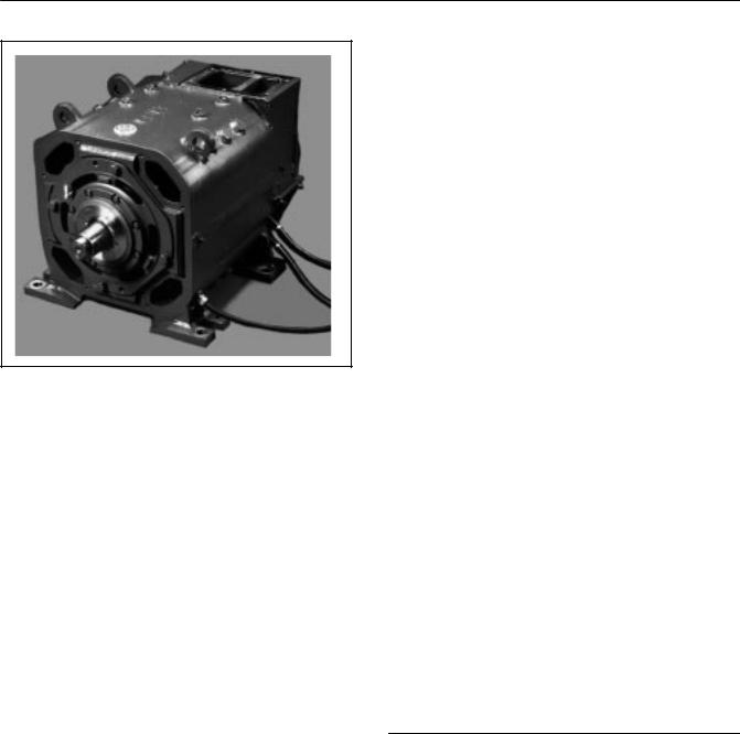
FIG. 1. GE752 VERTICAL DRILLING MOTOR.
E±39088.
INTRODUCTION
GE752 drilling motors designed for vertical operation, Fig. 1, are available in GE's UP, AUP, US and AUT series. This instruction provides inspection, maintenance and basic overhaul procedures for all of these motors. See Table I (page 3) for the models covered.
These motors have a ball bearing and a reinforced framehead at the commutator end to support the armature shaft vertically. They also have a shaft extension at the commutator end for installation of a brake. Mounting feet are precision machined to align with the rotational ovals of the motor.
Refer to GEK±64271C for coverage of GE752 models designed for horizontal operation.
GE752 motors are used by the oil and gas industry to power offshore and land±based drill rigs. Designed for vertical operation, they are d±c machines which require a nominal 750 volt d±c power source.
With suitable switching, they will operate equally well in either rotational direction. The following provides a listing of basic features.
The GE752UP and US models are of the ªShuntº class of motors which means they are separately excited with shunt wound fields.
The GE752AUP and AUT models are of the ªSeriesº class of motors which means they are self excited with series wound fields.
GE752UP and AUP motors are original design motors introduced in 1983. GE752US and AUT motors are Hi±Torque motors with:
1.A new shallow slot design and split conductor arrangement reduce heat generating eddy currents. Kapton insulation and new slot design allow more copper cross±section and allow the field windings and armature to operate at increased power levels.
2.The spiral groove commutator provides better commutator and brush cooling, better commutation ability, and increased brush life.
3.An additional six exhaust openings in the motor drive end framehead and revised air flow passage increases air flow and the motor's ability to transfer generated heat.
*Kapton is a registered trademark of E.I. duPont de Nemours & Co.
2
|
Vertical Drilling Motor, Type GE752, GEK±91584D |
||
|
TABLE 1. MODEL DIFFERENCES |
|
|
|
|
|
|
Motor |
Model Differences |
Superseded By |
|
|
|
|
|
752UP1 |
This is a shunt motor with the following distinctions: |
|
|
|
± Has internal greasing tubes for both drive end (pinion end) |
|
|
|
and commutator±end bearings |
|
|
|
± Has a double±ended shaft. |
|
|
|
|
|
|
752UP2 |
Same as UP1 except: |
|
|
|
± Has armored cable |
|
|
|
± Has no grease tubes at commutator end |
|
|
|
|
|
|
Motor |
Model Differences |
Superseded By |
|
|
|
|
|
752UP3 |
Same as UP2 except: |
|
|
|
± Has a single grease tube at drive end which is part of the |
|
|
|
framehead/bearing assembly for ease of armature |
|
|
|
disassembly. |
|
|
|
|
|
|
752UP3A |
Same as UP3 except: |
|
|
|
± Has class H Kapton wrapped exciting coils |
|
|
|
|
|
|
752UP4 |
Same as UP3A except: |
|
|
|
± Has an ABS certified shaft. |
|
|
|
|
|
|
752UP5 |
Same as UP3A except: |
|
|
|
± Has a thermal sensor embedded in each of its exciting and |
|
|
|
commutating coils. |
|
|
|
|
|
|
752UP6 |
Same as UP3A except: |
|
|
|
± Has an improved commutator±end bearing assembly and an |
|
|
|
ABS±certified armature shaft. |
|
|
|
|
|
|
752US1 |
This is a shunt motor with the following distinctions: |
|
|
|
± Same as UP3 except: |
|
|
|
± Has an AG type armature with an AF commutator and |
|
|
|
a standard AUP flash ring. |
|
|
|
± Has AG type commutating coils and poles with brazed |
|
|
|
instead of bolted connections. |
|
|
|
± Has air vents in the drive±end framehead |
|
|
|
± Has a frame specially machined for mounting the |
|
|
|
customer gearbox at the drive end. |
|
|
|
± Has a different drive±end grease arrangement. |
|
|
|
± Has rubber hardtop brushes instead of regular duplex |
|
|
|
brushes. |
|
|
|
|
|
|
752US2 |
Same as US1 except: |
|
|
|
± Has an improved commutator±end bearing assembly and an |
|
|
|
ABS±certified armature shaft. |
|
|
|
|
|
|
752AUP1 |
This is a series motor with the following distinctions: |
|
|
|
± Has internal greasing tubes for both drive end and |
|
|
|
commutator±end bearings |
|
|
|
± Has a double±ended shaft. |
|
|
|
|
|
|
752AUP2 |
Same as AUP1 except: |
|
|
|
± Has armored cable |
|
|
|
± Has no grease tubes at commutator end |
|
|
|
± Mounting feet have dowel holes for vertical mounting. |
|
|
|
|
|
|
3

GEK±91584D, Vertical Drilling Motor, Type GE752
TABLE 1 (Cont'd) MODEL DIFFERENCES
Motor |
Model Differences |
Superseded By |
|
|
|
752AUP3 |
Same as AUP2 except: |
|
|
± Has a single grease tube at drive end which is |
|
|
part of framehead/bearing assembly for ease of |
|
|
armature disassembly. |
|
|
|
|
752AUP4 |
Same as AUP3 except: |
|
|
± Has improved insulation for higher temperatures. |
|
|
|
|
752AUP5 |
Same as AUP4 except: |
|
|
± Has an improved commutator±end bearing assembly and an |
|
|
ABS±certified armature shaft. |
|
|
|
|
752AUT1 |
This is a series motor with the following distinctions: |
|
|
± Same as 752AUP3 except: |
|
|
± Has an AG type armature with an AF commutator and |
|
|
a standard AUP flash ring. |
|
|
± Has AG type commutator coils and poles with brazed |
|
|
instead of bolted connections. |
|
|
± Has air vents in the drive±end framehead |
|
|
± Has a frame specially machined for mounting the |
|
|
customer gearbox at the drive end. |
|
|
± Has a different drive±end grease arrangement. |
|
|
± Has rubber hardtop brushes instead of regular duplex |
|
|
brushes. |
|
|
|
|
752AUT2 |
Same as AUT1 except: |
|
|
± Has an improved commutator±end bearing assembly and an |
|
|
ABS±certified armature shaft. |
|
|
|
|
DATA
Max. Permissible Speed (rpm) . . . . . . . . . . . . . . . . . . . . . . . . . . . . . . . . . . . . . . . . . . . . . . . . . |
. . . . . . . . . . . . . . . |
. . . 1800 |
Max. Permissible Vibration (Commutator End) (in.) . . . . . . . . . . . . . . . . . . . . . . . . . . . . . . . . . |
. . . . . . . . . . . . . . |
. . 0.002 |
ªResistance at 25 C (Ohms): |
Min. |
Max. |
Armature |
|
|
Model 752UP . . . . . . . . . . . . . . . . . . . . . . . . . . . . . . . . . . . . . . . . . . . . . . . . . . . . . . . . . . |
0.00912 |
0.00949 |
Model 752AUP . . . . . . . . . . . . . . . . . . . . . . . . . . . . . . . . . . . . . . . . . . . . . . . . . . . . . . . . . |
0.00912 |
0.00949 |
Model 752US . . . . . . . . . . . . . . . . . . . . . . . . . . . . . . . . . . . . . . . . . . . . . . . . . . . . . . . . . . |
0.00749 |
0.00800 |
Model 752AUT . . . . . . . . . . . . . . . . . . . . . . . . . . . . . . . . . . . . . . . . . . . . . . . . . . . . . . . . . |
0.00749 |
0.00800 |
Exciting Field (With Cables) |
|
|
Model 752UP . . . . . . . . . . . . . . . . . . . . . . . . . . . . . . . . . . . . . . . . . . . . . . . . . . . . . . . . . . |
1.25 |
1.33 |
Model 752UP (After 3/88) . . . . . . . . . . . . . . . . . . . . . . . . . . . . . . . . . . . . . . . . . . . . . . . . |
1.13 |
1.22 |
Model 752AUP . . . . . . . . . . . . . . . . . . . . . . . . . . . . . . . . . . . . . . . . . . . . . . . . . . . . . . . . . |
0.00512 |
0.00558 |
Model 752US . . . . . . . . . . . . . . . . . . . . . . . . . . . . . . . . . . . . . . . . . . . . . . . . . . . . . . . . . . |
1.13 |
1.22 |
Model 752AUT . . . . . . . . . . . . . . . . . . . . . . . . . . . . . . . . . . . . . . . . . . . . . . . . . . . . . . . . . |
0.00486 |
0.00535 |
Commutating Field (With Cables) |
|
|
Model 752UP . . . . . . . . . . . . . . . . . . . . . . . . . . . . . . . . . . . . . . . . . . . . . . . . . . . . . . . . . . |
0.00508 |
0.00540 |
Model 752UP (After 3/88) . . . . . . . . . . . . . . . . . . . . . . . . . . . . . . . . . . . . . . . . . . . . . . . . |
0.00439 |
0.00534 |
Model 752AUP . . . . . . . . . . . . . . . . . . . . . . . . . . . . . . . . . . . . . . . . . . . . . . . . . . . . . . . . . |
0.00439 |
0.00477 |
Model 752US . . . . . . . . . . . . . . . . . . . . . . . . . . . . . . . . . . . . . . . . . . . . . . . . . . . . . . . . . . |
0.00432 |
0.00480 |
Model 752AUT . . . . . . . . . . . . . . . . . . . . . . . . . . . . . . . . . . . . . . . . . . . . . . . . . . . . . . . . . |
0.00432 |
0.00480 |
4

Vertical Drilling Motor, Type GE752, GEK±91584D
DATA (Cont'd)
Carbon Brushes
Type . . . . . . . . . . . . . . . . . . . . . . . . . . . . . . . . . . . . . . . . . . . . . . . . . . . . . . . . . . . . . . . . . . . . . . . . . . . . . . . . . . . . . . T900 Size (in.) . . . . . . . . . . . . . . . . . . . . . . . . . . . . . . . . . . . . . . . . . . . . . . . . . . . . . . . . . . . . . . 3/4 x 2±1/4 x 2
Minimum Brush Length (length at which brush becomes inoperative) (in.) . . . . . . . . . . . . . . . . . . . . . . . . . 1±3/32 (brush is measured on the longest side)
Spring Pressure on Brush, Preset (lb.) . . . . . . . . . . . . . . . . . . . . . . . . . . . . . . . . . . . . . . . . . . . . . . . . . . . . . . . . 10±12
Brushholder
Clearance to Commutator (in.) . . . . . . . . . . . . . . . . . . . . . . . . . . . . . . . . . . . . . . . . . . . . . . . . . . . . . . . . . . . . 1/16±3/32
Clamp Bolt Torque (lb.±ft.) . . . . . . . . . . . . . . . . . . . . . . . . . . . . . . . . . . . . . . . . . . . . . . . . . . . . . . . . . . . . . . . . . 225±250
Commutator
Side Mica Thickness (in.) . . . . . . . . . . . . . . . . . . . . . . . . . . . . . . . . . . . . . . . . . . . . . . . . . . . . . . . . . . . . . . . . . . . . 0.060 Slot Depth (in.) . . . . . . . . . . . . . . . . . . . . . . . . . . . . . . . . . . . . . . . . . . . . . . . . . . . . . . . . . . . . . . . . . . . . . . . . . . . . . 0.047 Undercutting Saw:
Width (in.) . . . . . . . . . . . . . . . . . . . . . . . . . . . . . . . . . . . . . . . . . . . . . . . . . . . . . . . . . . . . . . . . . . . . . . . . . . . . 0.063 Diameter (in.) . . . . . . . . . . . . . . . . . . . . . . . . . . . . . . . . . . . . . . . . . . . . . . . . . . . . . . . . . . . . . . . . . . . . . . . . . . 1.000
Diameter: (in.)
New . . . . . . . . . . . . . . . . . . . . . . . . . . . . . . . . . . . . . . . . . . . . . . . . . . . . . . . . . . . . . . . . . . . . . . . . . . . . . . . . . 16.625 Worn (minimum permissible) . . . . . . . . . . . . . . . . . . . . . . . . . . . . . . . . . . . . . . . . . . . . . . . . . . . . . . . . . . . . 15.375 Riser Width (minimum permissible) (in.) . . . . . . . . . . . . . . . . . . . . . . . . . . . . . . . . . . . . . . . . . . . . . . . . . . . . . . . 0.625
Dust Groove: (in.)
Width . . . . . . . . . . . . . . . . . . . . . . . . . . . . . . . . . . . . . . . . . . . . . . . . . . . . . . . . . . . . . . . . . . . . . . . . . . . . . . . . . 0.250
Depth . . . . . . . . . . . . . . . . . . . . . . . . . . . . . . . . . . . . . . . . . . . . . . . . . . . . . . . . . . . . . . . . . . . . . . . . . . . . . . . . . 0.125
Commutator (Cont'd)
Concentricity ± New Commutator (in.)
Total Indicated Runout, TIR . . . . . . . . . . . . . . . . . . . . . . . . . . . . . . . . . . . . . . . . . . . . . . . . . . . . . . . . . . . . . . 0.001 Variation of Indicator Runout within (in.)
any Group of 20 Bars . . . . . . . . . . . . . . . . . . . . . . . . . . . . . . . . . . . . . . . . . . . . . . . . . . . . . . . . . . . . . . . . . . 0.0004 Variation of Indicator Reading between (in.)
any Two Adjacent Bars . . . . . . . . . . . . . . . . . . . . . . . . . . . . . . . . . . . . . . . . . . . . . . . . . . . . . . . . . . . . . . . . 0.0001 Concentricity ± Used Commutator (in.)
(Resurface if runout exceeds 0.010 TIR or 0.003 within any group of 6 bars):
After Resurfacing, TIR (in.) . . . . . . . . . . . . . . . . . . . . . . . . . . . . . . . . . . . . . . . . . . . . . . . . . . . . . . . . . . 0.001 Bar±To±Bar Test (500 v) Voltage
Variation Bar±To±Bar . . . . . . . . . . . . . . . . . . . . . . . . . . . . . . . . . . . . . . . . . . . . . . . . . . . . . . . . . . . . . . . . . . +/± 5%
Armature Balance |
|
|
Commutator End . . . . . . . . . . . . . . . . . . . . . . . . . . . . . . . . . . . . . . . . . . . . . . . . . . . . . . . |
. . . . . . . . |
12 grams (0.42 oz.) |
Drive End . . . . . . . . . . . . . . . . . . . . . . . . . . . . . . . . . . . . . . . . . . . . . . . . . . . . . . . . . . . . . . |
. . . . . . . |
10 grams (0.35 oz.) |
Armature Bearings |
Min. |
Max. |
Diametral Clearance, Assembled (In.) |
|
|
Drive End . . . . . . . . . . . . . . . . . . . . . . . . . . . . . . . . . . . . . . . . . . . . . . . . . . . . . . . . . |
0.005 |
0.009 |
Commutator End . . . . . . . . . . . . . . . . . . . . . . . . . . . . . . . . . . . . . . . . . . . . . . . . . . . |
0.0005 |
0.0035 |
Runout Measured from Shaft to Outer Race (in.): |
|
|
Drive End . . . . . . . . . . . . . . . . . . . . . . . . . . . . . . . . . . . . . . . . . . . . . . . . . . . . . . . . . . |
. . . . . . . . |
. . . . . . . . . . . 0.004 |
Commutator End . . . . . . . . . . . . . . . . . . . . . . . . . . . . . . . . . . . . . . . . . . . . . . . . . . . . |
. . . . . . . . |
. . . . . . . . . . . 0.003 |
5

GEK±91584D, Vertical Drilling Motor, Type GE752
DATA (Cont'd)
Pole Bore Diameter (measured at center of pole) (in.) |
|
|
Motors: |
Min. |
Max. |
Exciting Poles (Shunt models) . . . . . . . . . . . . . . . . . . . . . . . . . . . . . . . . . . . . . . . |
19.606 |
19.640 |
Exciting Poles (Series models) . . . . . . . . . . . . . . . . . . . . . . . . . . . . . . . . . . . . . . . |
19.613 |
19.640 |
Commutating Poles (Both Shunt and Series models) . . . . . . . . . . . . . . . . . . . . |
19.956 |
19.998 |
Impedance Test |
|
Voltage Drop |
|
|
(Coiled Frame Without Armature): |
|
Min. |
Max. |
|
Exciting Field (With Cables) |
|
|
|
|
Model 752UP (0.5 Amps @ 60 Hz) . . . . . . . . . . . . . . . . . . . . . . . . . . . . . . . . . . . . . . . . |
59.0 |
66.6 |
||
Model 752AUP (24 Amps @ 60 Hz) . . . . . . . . . . . . . . . . . . . . . . . . . . . . . . . . . . . . . . . |
13.1 |
15.6 |
||
Model 752US (0.5 Amps @ 60 Hz)* . . . . . . . . . . . . . . . . . . . . . . . . . . . . . . . . . . . . . . . |
59.0 |
66.6 |
||
Model 752AUT (24 Amps @ 60 Hz) . . . . . . . . . . . . . . . . . . . . . . . . . . . . . . . . . . . . . . . |
13.1 |
15.6 |
||
Commutating Field (With Cables) |
|
|
|
|
Model 752UP (24 Amps @ 60 Hz) . . . . . . . . . . . . . . . . . . . . . . . . . . . . . . . . . . . . . . . . |
7.3 |
8.5 |
||
Model 752AUP (24 Amps @ 60 Hz) . . . . . . . . . . . . . . . . . . . . . . . . . . . . . . . . . . . . . . . |
7.2 |
8.5 |
||
Model 752US (24 Amps @ 60 Hz)** . . . . . . . . . . . . . . . . . . . . . . . . . . . . . . . . . . . . . . . |
7.3 |
8.1 |
||
Model 752AUT (24 Amps @ 60 Hz) . . . . . . . . . . . . . . . . . . . . . . . . . . . . . . . . . . . . . . . |
7.7 |
8.5º |
||
Lubrication* ± Armature Bearings |
|
|
|
|
Grease Capacities (oz.): |
|
|
|
|
Drive End . . . . . . . . . . . . . . . . . . . . . . . . . . . . . . . . . . . . . . . . . . . . . . . . . . . . . . . . . . . . . |
. |
. . . . . . . . |
. . . . . . . . . 39.1 |
|
Commutator End . . . . . . . . . . . . . . . . . . . . . . . . . . . . . . . . . . . . . . . . . . . . . . . . . . . . . . . |
. |
. . . . . . . . |
. . . . . . . . . 31.8 |
|
Lubricant . . . . . . . . . . . . . . . . . . . . . . . . . . . . . . . . . . . . . . . . . . . . . . . . . . . . . . . . . . . . . . |
. |
. . . . . . . |
GE±D6A2C10* |
|
**See Grease Specification at the end of the DATA table.
Weights (lb.) (approx.)
Complete . . . . . . . . . . . . . . . . . . . . . . . . . . . . . . . . . . . . . . . . . . . . . . . . . . . . . . . . . . . . . . . . . . . . . . . . . . . . . . . . . . . 6720
Armature Only . . . . . . . . . . . . . . . . . . . . . . . . . . . . . . . . . . . . . . . . . . . . . . . . . . . . . . . . . . . . . . . . . . . . . . . . . . . . . . 2100
High±Potential Test |
|
60 Hz, a±c, to ground for one minute (All Windings) (volts): |
|
New or Rewound Armature . . . . . . . . . . . . . . . . . . . . . . . . . . . . . . . . . . . . . . . . . . . . . . |
. . . . . . . . . . . . . . . . . 3500 |
Reconditioned . . . . . . . . . . . . . . . . . . . . . . . . . . . . . . . . . . . . . . . . . . . . . . . . . . . . . . . . . . |
. . . . . . . . . . . . . . . . 2000 |
Megger Test |
Minimum Megohmmeter |
Reading (megohms) |
|
Shunt Models |
|
A1±A2 . . . . . . . . . . . . . . . . . . . . . . . . . . . . . . . . . . . . . . . . . . . . . . . . . . . . . . . . . . . . . |
. . . . . . . . . . . . . . . . . . 1.4 |
F1±F2 . . . . . . . . . . . . . . . . . . . . . . . . . . . . . . . . . . . . . . . . . . . . . . . . . . . . . . . . . . . . . |
. . . . . . . . . . . . . . . . . . 0.3 |
Series Models |
|
A1±A2 . . . . . . . . . . . . . . . . . . . . . . . . . . . . . . . . . . . . . . . . . . . . . . . . . . . . . . . . . . . . . |
. . . . . . . . . . . . . . . . . . 1.4 |
F1±F2 . . . . . . . . . . . . . . . . . . . . . . . . . . . . . . . . . . . . . . . . . . . . . . . . . . . . . . . . . . . . . |
. . . . . . . . . . . . . . . . . . 1.4 |
* With Commutating Poles (CP) out. **Excitation Field in.
6

|
Vertical Drilling Motor, Type GE752, GEK±91584D |
|
|
DATA (Cont'd) |
|
Motor Ratings* |
|
Continuous |
|
|
Max. HP |
Shunt (UP)
Volts . . . . . . . . . . . . . . . . . . . . . . . . . . . . . . . . . . . . . . . . . . . . . . . . . . . . . . . . . . . . . . . . . . . . . . . . . . . . . . . . . . . . 750
Armature Amps . . . . . . . . . . . . . . . . . . . . . . . . . . . . . . . . . . . . . . . . . . . . . . . . . . . . . . . . . . . . . . . . . . . . . . . . . 1050
Field Amps . . . . . . . . . . . . . . . . . . . . . . . . . . . . . . . . . . . . . . . . . . . . . . . . . . . . . . . . . . . . . . . . . . . . . . . . . . . . . . . 57
RPM . . . . . . . . . . . . . . . . . . . . . . . . . . . . . . . . . . . . . . . . . . . . . . . . . . . . . . . . . . . . . . . . . . . . . . . . . . . . . . . . . . 1050
Horsepower . . . . . . . . . . . . . . . . . . . . . . . . . . . . . . . . . . . . . . . . . . . . . . . . . . . . . . . . . . . . . . . . . . . . . . . . . . . . 1000
Series (AUP)
Volts . . . . . . . . . . . . . . . . . . . . . . . . . . . . . . . . . . . . . . . . . . . . . . . . . . . . . . . . . . . . . . . . . . . . . . . . . . . . . . . . . . . . 750
Armature Amps . . . . . . . . . . . . . . . . . . . . . . . . . . . . . . . . . . . . . . . . . . . . . . . . . . . . . . . . . . . . . . . . . . . . . . . . . 1050
Field Amps . . . . . . . . . . . . . . . . . . . . . . . . . . . . . . . . . . . . . . . . . . . . . . . . . . . . . . . . . . . . . . . . . . . . . . . . . . . . 100%
RPM . . . . . . . . . . . . . . . . . . . . . . . . . . . . . . . . . . . . . . . . . . . . . . . . . . . . . . . . . . . . . . . . . . . . . . . . . . . . . . . . . . . 975
Horsepower . . . . . . . . . . . . . . . . . . . . . . . . . . . . . . . . . . . . . . . . . . . . . . . . . . . . . . . . . . . . . . . . . . . . . . . . . . . . 1000
*NOTE: With 2800 SCFM air flow. |
|
|
|
|
Motor Ratings** |
Continuous |
Continuous |
Intermittent |
|
|
Max. HP |
Max. Torque |
Duty Cycle |
|
Shunt (US) |
|
|
|
|
Volts . . . . . . . . . . . . . . . . . . . . . . . . . . . . . . . . . . . . . . . . . . . |
. . . 750 |
650 |
750 |
|
Armature Amps . . . . . . . . . . . . . . . . . . . . . . . . . . . . . . . . . |
. . 1185 |
1250 |
1435 |
|
Field Amps* . . . . . . . . . . . . . . . . . . . . . . . . . . . . . . . . . . . . |
. . . 60 |
60 |
60 |
|
RPM . . . . . . . . . . . . . . . . . . . . . . . . . . . . . . . . . . . . . . . . . . . |
. 1040 |
900 |
1065 |
|
Torque . . . . . . . . . . . . . . . . . . . . . . . . . . . . . . . . . . . . . . . . . . |
. 5705 |
5995 |
6745 |
|
Horsepower . . . . . . . . . . . . . . . . . . . . . . . . . . . . . . . . . . . . . |
. 1130 |
1030 |
1365 |
|
Series (AUT) |
|
|
|
|
. . . . . . . . . . . . . . . . . . . . . . . . . . . . . . . . . . . . . . . . . . . .Volts |
. . 750 |
570 |
750 |
|
Armature Amps . . . . . . . . . . . . . . . . . . . . . . . . . . . . . . . . . . |
. 1150 |
1250 |
1400 |
|
. . . . . . . . . . . . . . . . . . . . . . . . . . . . . . . . . . .Field Strength |
. 100% |
100% |
100% |
|
RPM |
965 |
700 |
920 |
|
|
||||
Torque . . . . . . . . . . . . . . . . . . . . . . . . . . . . . . . . . . . . . . . . . . |
. 5900 |
6620 |
7530 |
|
Horsepower . . . . . . . . . . . . . . . . . . . . . . . . . . . . . . . . . . . . . |
. 1085 |
880 |
1320 |
|
|
|
|
|
|
**NOTE: With 2800 SCFM air flow and ABS temperature rise standards, 155 C over 40 C ambient.
Grease Specification
D6A2C10 grease is a lithium soap base grease with added antioxidant. It contains an oil of heavy viscosity and is especially suitable for high speed, high temperature open or shielded bearings in drilling motors. Specifications:
Worked Consistency, 77 F, MM/10 . . . . . . . . . . . . . . . . . . . . . . . . . . . . . . . . . . . . . . . . . . . . . . . . . . . . . 220±240 Dropping Point, Degrees F (Min) . . . . . . . . . . . . . . . . . . . . . . . . . . . . . . . . . . . . . . . . . . . . . . . . . . . . . . . . . . . 380 Mineral Oil Viscosity At 100 F, SSU . . . . . . . . . . . . . . . . . . . . . . . . . . . . . . . . . . . . . . . . . . . . . . . . . . . . 475±525 Free Alkali, Percent (Max) . . . . . . . . . . . . . . . . . . . . . . . . . . . . . . . . . . . . . . . . . . . . . . . . . . . . . . . . . . . . . . . . . 0.50 Free Acid, Percent (Max) . . . . . . . . . . . . . . . . . . . . . . . . . . . . . . . . . . . . . . . . . . . . . . . . . . . . . . . . . . . . . . . . . . . Nil Color . . . . . . . . . . . . . . . . . . . . . . . . . . . . . . . . . . . . . . . . . . . . . . . . . . . . . . . . . . . . . . . . . . . . . . . . . . . . . . . . . Amber Base (With Antioxidant) . . . . . . . . . . . . . . . . . . . . . . . . . . . . . . . . . . . . . . . . . . . . . . . . . . . . . . . . . . . . . . . . Lithium Oxidation Resistance Time To Reach 20 psi Drop At 210 F, Hr. (Min) . . . . . . . . . . . . . . . . . . . . . . . . . . 1000 Corrosion . . . . . . . . . . . . . . . . . . . . . . . . . . . . . . . . . . . . . . . . . . . . . . . . . . . . . . . . . . . . . . . . . . . . . . . . . Must Pass Approved Vendor . . . . . . . . . . . . . . . . . . . . . . . . . . . . . . . . . . . . . . . . . . . . . . . . . . . . . . . . . . . . . . . . . . . . . Shell Oil Brand Name . . . . . . . . . . . . . . . . . . . . . . . . . . . . . . . . . . . . . . . . . . . . . . . . . . . . . . . . . . . . . . . . . . . . . . Cyprina RA
7

GEK±91584D, Vertical Drilling Motor, Type GE752
SPECIAL TOOLS
AND EQUIPMENT
CAUTION: This machine is of open splash±proof construction. It is force±ventilated and requires an ample supply of cooling air. The cooling air should not contain combustible gases. If it is applied in an environment which may contain combustible gases, an adequate supply of non± contaminated cooling air must be provided.
The following items are required to maintain, repair and overhaul the motors:
Part
Megohmmeter (or ªMeggerº*)
600 volts . . . . . . . . . . . . . . . . 111X910 or equivalent
Voltmeter . . . . . . . . . . Simpson Multimeter, Model 260
or equivalent
Puller Tools . . . . . . . . . . . . . . . . . . . . . . . 41E903423G1
Commutator Grinder . . . . . . . . . . . . . . . . . 427C592G1
Resurfacing Stones:
Medium Grade . . . . . . . . . . . . . . . . . . . 8828492P11
Finish Grade . . . . . . . . . . . . . . . . . . . . . . 8828492P8
Brush±Seater Stone (White) . . . . . . . . . . . 106X98
Lifting Eye . . . . . . . . . . . . . . . . . . . . . . . . . . P9945894P8
Crows±Foot Pressing Tool . . . . . . . . . . 41C685430G1
Ball and Socket Tool . . . . . . . . . . . . . . . 41C685080G1
Guide Pins, Three (3) Recommended
for Armature Asm. In Frame . . . . . . . . 6717114P1
Spanner Wrench . . . . . . . . . . . . . . . . . . . . . 8843522G1
Spring Scale (for brush±spring
pressure check) . . . . . . . . . . . . . . 0±20 lb. capacity
Hub Assembly Gauge . . . . . . . . . . . . . . 41D790941G1
Hub Puller (Less Pump) . . . . . . . . . . . . 41B535703G1
Pump (For Above) . . . . . . . . . . . . . . . . . . . . 8843947G1
GROUNDING INSTRUCTIONS
Grounding motor frames is required to safeguard personnel from electric shock in event of an insulation failure in the machine.
WARNING: Failure to properly ground electrical equipment may expose personnel to a potentially hazardous condition in which serious or fatal injury from electrical shock is possible.
Grounding conductors must be provided between the machine frame and the supporting structure to avoid hazardous potential difference between the machine frame and the adjacent surface on which a person may be standing while touching the machine.
NOTE: This type of ground connection is referred to in electrical standards as ªequipment groundingº or ªenclosure groundingº which is not to be confused with ªsystemº or ªcircuitº grounding. Drilling drive systems normally do not have intentional circuit ground connections, except through high impedance detectors.
Grounding conductors must be provided on drilling units on which the construction of the unit and/or the installation of the machines do not inherently insure positive grounding of the equipment. Examples are those portable (modular) platform rigs and land rigs which do not already have ground cables to all machinery structures. Offshore rigs with equipment fastened to the
*Tradename of James G. Biddle Co. |
FIG. 2. DRILLING MOTOR ± FRAME GROUNDING |
|
CABLE CONNECTIONS. E±28717. |
||
|
8

Vertical Drilling Motor, Type GE752, GEK±91584D
decks by bolting or welding should not require additional grounding. (References: ABS Rules for Building and Classing Steel Vessels, Section 35.9.6, and IEEE Standard 45±1977, Recommended Practice for Electrical Installations on Shipboard, Section 21.4.)
GROUNDING PROCEDURES (Fig. 2)
Most GE drilling machines have extra tap blocks on the frame for mounting of the connection boxes. One of these may be used for attaching the grounding cable. If one is not available, use the lower chain case mounting boss on the end opposite the drive end in accordance with Step 2.
1.To attach the ground cable to a tap block, obtain a 0.75±10 bolt with length of 1.0 to 1.5 in. and a lockwasher. Also obtain a cable lug to fit the ground cable and large enough for the 0.75 diameter bolt.
2.To attach the cable to the chain case boss, obtain a 1.25±7 bolt with length of 1.0 to 1.75 in. and a lockwasher. Prepare a copper plate at least 1/8 in. thick with a 1.25 in. diameter hole for bolting to the chain case boss, and with enough extra area for holes to attach a cable lug. Drill hole(s) in plate for cable lug. Clean all paint, rust and oil from the chain case boss and bolt the copper plate to the chain case boss.
3.Prepare a ground conductor* long enough to run from the motor frame to an existing ground conductor system or to a suitable equipment ground point as defined by the National Electrical Code Article 250 or other applicable regulation. Check that the system ground detector is also connected to the Common ground point for the rig and make connection if necessary.
4.Install terminal lugs on cable. Remove paint, rust and oil from the surfaces to which the cables are to be attached and bolt the lugs securely to these surfaces.
*Use 4/0 size or larger copper cable for GE752 machines. (Reference: National Electrical Code, 1978 Edition, Table 250±95.)
5.Use a digital ohmmeter to check that the bolted connections are solid, low resistance connections from the cable conductor to the ground point and to the motor frame. The meter reading should be 0.2 ohms or less.
OVERHAUL
Overhaul intervals will depend on the severity of ser vice seen by the machine. However, General Electric Co. recommends that an overhaul be performed every 18,000 hours (approximately every two years) on all machines subjected to normal operation.
The motor should be removed, disassembled, cleaned, inspected and reconditioned as necessary (including varnish treatment of armature and fields). Motor bearings should be repacked with grease. See the DATA section for grease type and quantity.
LUBRICATION
Periodic lubrication is required on all GE752 drilling machines designed for vertical operation between scheduled overhaul periods. Every six months or 2500 hours, whichever comes first, apply approximately 2 oz. of grease at each end.
GREASE TUBES AND PIPE PLUGS
The following lists grease tube and pipe plug configurations for all models covered in this publication:
1.UP1 and AUP1 Ð Four grease tubes with pipe plugs, two at each end.
2.UP2 and AUP2 Ð Two grease tubes with pipe plugs, one at each end.
3.UP3, UP3A, UP4, UP5, UP6, AUP3, AUP4, AUP5 ± One grease tube with a pipe plug at the drive end, one pipe plug only at the commutator end.
4.US1, US2, AUT1, AUT2 ± One pipe plug only at each end.
Pipe plugs are provided on bearing caps and on the ends of all grease tubes to prevent the ingress of dirt or other contamination.
Remove the pipe plugs and install grease fittings to facilitate lubrication. Replace the pipe plugs after adding lubricant. See the DATA section for recommended grease type.
9
GEK±91584D, Vertical Drilling Motor, Type GE752
INSPECTION
MONTHLY
Inspect the exterior of the machine, including cables, for damage.
Covers, Seals, Latches
Clean the outside of the machine and remove the inspection covers. Use clean, dry compressed air and blow the dirt and carbon dust from the interior of the machine.
WARNING: When using compressed air for cleaning purposes, flying debris and particles may present a hazard to personnel in the immediate area. Personnel should be provided with, and trained in the use of, personal protective equipment as specified by applicable federal or state safety regulations.
Check exterior covers to be sure felt seals are intact. If seals are missing or covers are damaged, replace seals or covers as necessary. Make sure covers fit properly and cover latches work properly.
Brushholders (Fig. 5)
Satisfactory operation of the drilling motor requires the brushholders to be in good condition. Of particular importance is the inside dimension of the carbonways. Operation may also be impaired by brushholders which have been mechanically damaged or sustained damage as the result of motor flashovers.
Inspect the brushholders for damage. If they require replacement, refer to BASIC REPAIRS, Brushholder Replacement section for instructions.
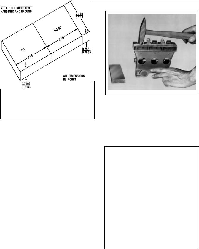
When new, brushholder carbonways should measure 0.753 +/±0.002 in x 2.2575 +/±0.0025 in. If or when the 0.753 in. dimension exceeds 0.765 in., the brushholder should be scrapped. If it falls between 0.758 and 0.765 in., the carbonway can be restored to its proper dimension according to the following instructions:
1.Remove the brushholder. Position it as shown in Fig. 3 and tap the metal ridge with a hammer.
FIG. 3. RESIZING BRUSHHOLDER
CARBONWAYS. E±11281.
Start at one end and work along the ridge to the other end.
2.Check progress frequently by means of a ªGo/ No±Goº gage made to the dimensions shown in Fig. 4.
FIG. 4. BRUSHHOLDER CARBONWAY
GAGE. E±11283A.
10
Vertical Drilling Motor, Type GE752, GEK±91584D
3.Continue tapping as described in Step 1 until the 0.753 dimension falls between 0.751 and 0.755.
4.If, due to excessive pounding, the inside dimension becomes less than 0.751 in., file back to size with a fine mill file.
Additional repairs can be made to restore damaged brushholder bodies. Brushholder damage is fairly typical when flashovers have occured, resulting in some burning or melting of metal at the corners of the brushholder. Metal thus removed can be restored according to the following instruction, unless more than 1/4 in. buildup of metal is required in the affected area, in which case the brushholder should be scrapped. Proceed as follows:
1.Thoroughly clean the affected area by wire brushing, and grind off any metal flow resulting from a flashover.
2.Apply a suitable brazing flux such as GE±A10B15 to the area to be built up.
3.Insert a carbon brush into the brushholder to prevent the brazing material from flowing into the carbonway.
4.Using a brazing torch and a 1/16 in. diameter brass brazing rod, puddle in sufficient metal to restore the metal that had been removed.
5.Check the carbonway for size with the ªGo/No± Goº gage after the brushholder has cooled to room temperature.
6.Resize as required using the preceding method.
Brushholder Sleeves
spots caused by flashovers. Replace any damaged brushholder or one having a damaged sleeve.
WARNING: MEK is a volatile solvent. The fumes should not be inhaled. Use only in a well±ventilated area and take adequate precautions to protect eyes, skin and hands.
NOTE: Never paint these sleeves. Periodically wipe them clean with a dry cloth or a cloth dipped in an approved non±oily cleaning solvent.
Inspect the brushholder cables and make sure all terminal bolts and all brushholder clamp bolts are tight.
Brush Spring Pressure
Lift the brush pressure fingers to the ªtoggled±upº position, Fig. 5, and check for free movement of the spring assembly.
Inspect the brush springs for obvious failure or damage. Check brush±spring pressure by comparing spring pressure with a spring known to be good. Refer to the DATA section for brush spring±pressure value.
BRUSH PRESSURE FINGER (IN TOGGLED±UP POSITION)
TEFLON |
PRESSURE |
|
SLEEVES |
||
SPRING |
||
|
||
|
CARBONWAY |
BRUSH±SHUNT
TERMINAL
SCREWS
Use a clean, lintless cloth and wipe dirt and grease from the Teflon* brushholder sleeves, Fig. 5. If necessary, use a cleaner such as MEK (methyl ethyl ketone) to clean the sleeves. Inspect sleeves for cracks and thin
FIG. 5. BRUSH SPRING ARRANGEMENT.
E±18963.
*Product of E.I. duPont de Nemours Company.
11

GEK±91584D, Vertical Drilling Motor, Type GE752
Brushes |
brush±shunt terminal connections and all brush- |
|
holder cable connections are tight. |
Brush wear is determined by measuring actual brush length from the top of the carbon. Lift the brush spring, remove the brush and measure brush length on the longest side.
NOTE: If brush replacement is not required, be sure that brushes are of sufficient length to last until the next inspection.
If one or more brushes are worn to or near the minimum length listed in the DATA section it is generally recommended that all twelve brushes be replaced at the same time.
WARNING: To avoid possible electrical shock or injury from rotating equipment, do not remove or replace brushes while equipment is energized or rotating.
If brushes are to be replaced, see the BASIC REPAIRS, Brush Replacement section for brush installation instructions.
If brushes are not to be replaced, the following brush inspection should be made:
CAUTION: When replacing brushes, use only the GE recommended grade. Mixing of brush grades in the same motor or changing brushes to another grade may seriously affect commutation, surface film, commutator and brush life. See the DATA section for brush grade.
1.Inspect all brushes to be sure they are not chipped or broken. Make sure brush shunts are not frayed or broken. Replace any brush which shows damage of any kind.
NOTE: Chipped, burned or rough±faced brushes may indicate the commutator needs resurfacing.
2.Move the brushes up and down in their carbonways to be sure brushes slide freely.
3.Check brush shunts to be sure they are not twisted or out of position, Fig. 6. Make sure all
Commutator
Inspect the commutator for possible flashover damage. The commutator should be clean, smooth, glossy and free of high mica, high bars, flat spots or rough surfaces.
If there are indications that the commutator is out± of±round (as evidenced by variations in width of the ridge between brush paths), check the concentricity of the commutator with a dial indicator. Condemning limits for concentricity are listed in the DATA section.
If the commutator requires grinding, refer to Commutator Resurfacing in the BASIC REPAIRS section of this manual for instructions.
Creepage Band
Clean the creepage band (located on the commutator cap) with a clean cloth dipped in an approved solvent. Inspect the band for possible flashover damage.
Make sure the creepage band is tight on the commutator cap.
Flash Ring
Examine the flash ring for possible flashover damage. Wipe the flash ring clean. Keep ring free of dirt and varnish.
BRUSH |
|
KEEP SHUNTS CLEAR |
SHUNTS |
|
OF LEVER ARMS |
|
|
|
|
|
|
FIG. 6. CORRECT POSITION OF BRUSH
SHUNTS. E±22568.
12

|
Vertical Drilling Motor, Type GE752, GEK±91584D |
|
Insulation |
ger over the center of each brush. See the DATA |
|
|
section for limits. |
|
Measure the insulation resistance with a meg± ohmmeter (Megger) to determine the condition of the insulation. If reading is low, make a further inspection to determine if insulation failure or excessive moisture is causing the low megohmmeter reading. Correct the cause of low readings before returning the motor to service.
Inspect all accessible parts of the field coil insulation for cracking and evidence of overheating.
Power Cables
Inspect the power cables for signs of excessive heating, poor insulation or mechanical damage. Assure all terminals are tight. Replace any cables which show low insulation resistance or will not stand 75% above rated voltage.
Mounting Bolts
Check all mounting bolts to assure tightness.
SEMI±ANNUALLY
1.Perform inspection operations listed under Monthly section.
2.Refer to the DATA section for the Brushholder Clearance dimension, and check the clearance between the brushholders and the commutator surface.
If clearance adjustment is required, refer to the BASIC REPAIRS, Brushholder Clearance Adjustment section for instructions.
BASIC REPAIRS
BRUSH REPLACEMENT
NOTE: Brush spring pressure is pre±set and non±adjustable for the brushholders used on these machines. Any brushholder that is damaged or has a low spring pressure should be replaced before installing new brushes. Spring pressure can be measured with a 20±lb. spring scale pulling radially on the brush pressure fin-
1.Remove the commutator inspection covers.
2.Disconnect the brush shunt from the terminal screw, Fig. 5, located on the brushholder body.
3.Lift the pressure finger away from the brush to the toggled±up position. Remove the brush.
4.Use dry, compressed air and blow the carbon dust from the carbonway.
WARNING: When using compressed air for cleaning purposes, flying debris and particles may present a hazard to personnel in the immediate area. Personnel should be provided with, and trained in the use of, personal protective equipment as specified by applicable federal or state safety regulations.
5.Insert a new brush and make sure it slides freely in the carbonway.
6.Carefully lower the pressure finger on the brush. Do not allow the finger to snap down on the brush; this could damage the brush.
7.Bolt the brush shunt terminals to the brushholder(s). Arrange the brush shunt strands so they clear the pressure fingers, Fig. 6, and tighten the terminal screw(s). Make sure brush shunts are not positioned under the pressure fingers. Check and tighten all brushholder cable connections.
8.Seat the new brushes with a white seater stone.
CAUTION: When replacing brushes, use the GE recommended grade. Mixing of brush grades in the same motor or changing brushes to another grade will seriously affect commutation, surface film, commutator and brush life. See the DATA section for brush grade.
BRUSHHOLDER REPLACEMENT
Removal
1.Remove brushes from the brushholders and cover the commutator with heavy paper.
2.Disconnect the cable from the brushholder(s) involved.
13

GEK±91584D, Vertical Drilling Motor, Type GE752
3. Remove bolt, washer and brushholder clamp. |
COMMUTATOR RESURFACING |
Lift the brushholder out of the frame. |
|
Installation |
Prior to resurfacing, consider the following: |
|
1.Position the brushholder in the frame with the brushholder studs resting in the clamp surfaces of the brushholder support.
2.Install bolt and washer. Tighten bolt but do not torque until the brushholder±to±commutator clearance has been established. Refer to Brushholder Clearance Adjustment section for instructions to adjust brushholder clearance.
3.After brushholder clearance has been set, connect the brushholder cable and remove protective paper from commutator surface.
4.Check brushes to insure they exceed the minimum brush length dimension and are free of any damage. If they are long enough and are not damaged, they can be re±used. If not, replace with new brushes.
BRUSHHOLDER CLEARANCE
ADJUSTMENT
Refer to the DATA section for the brushholder±to± commutator clearance dimension and adjust brushholder as follows:
1.The brush surface diameter of the commutator must not be less than the minimum permissible diameter, listed in the DATA section, after resurfacing operations are completed.
2.The commutator can be resurfaced by sanding, stoning or grinding. Choose the method to be used based on the condition of the commutator.
NOTE: Outside power will be required to operate the motor for the following commutator±resurfacing procedure.
WARNING: For the safety of personnel during resurfacing operations, the following safety precautions must be adhered to:
1.A second person must be at the auxiliary power (welder) control station, ready to shut off power in case of an emergency during the grinding operation.
2.The grinding operator should wear goggles and a dust mask when resurfacing or blowing out the commutator.
3.To avoid electrical shock, do not touch any part of the machine interior during grinding operations.
1.Remove the brushes.
CAUTION: Do not allow the brushholder to touch, bump or rest on the commutator.
2.Insert a fiber gauge (equal in thickness to the clearance dimension) between the commutator and the brushholder. (Loosen brushholder first if below minimum allowable clearance.)
Do NOT use a metallic gauge.
3.Loosen the brushholder support bolt and move the brushholder against the fiber gauge so clearance±to±commutator is the same as the gauge thickness.
4.Torque bolt to 225±250 ft.±lb. and recheck the brushholder clearance gap.
Preparation For Operating Series Model
Machines For Commutator Resurfacing
1.Break the coupling (if applicable) so the machine can be operated from a d±c welding set or other outside d±c power source.
2.Lift all the brushes except two of opposite polarity (adjacent brushholders) which are necessary to operate the motor.
3.Connect the machine to an outside source of controlled d±c power; such as a 3±5 kw, 100 vdc welding set which is capable of driving it at a speed of 900±1000 rpm.
4.Refer to Fig. 7 for diagram of connections to run a series machine from a welding set. Connect
14

Vertical Drilling Motor, Type GE752, GEK±91584D
FIG. 7. DIAGRAM OF CONNECTIONS TO RUN A SERIES MACHINE FROM A WELDING SET.
E±28718.
leads so machine will operate as a series motor, and the armature will rotate counterclockwise (viewed from the commutator end).
Preparation For Operating Shunt Model
Machines For Commutator Resurfacing
1.Break the coupling (if applicable) so the machine can be run from a d±c power source.
2.Lift all brushes except two of opposite polarity (adjacent brushholders) which are necessary to operate the motor.
3.Connect the machine to an outside source of controlled d±c power, Fig. 8.
4.Apply power as follows:
a.Increase the field supply (0±50 v) to 32.0 volts at 25 amps.
b.Increase the armature supply (0±150 v) to 150 volts.
c.Slowly decrease the field supply to bring the speed up to 1000 rpm.
FIG. 8. CONNECTIONS TO RUN A SHUNT MACHINE FROM A D±C POWER SOURCE.
E±23930A.
NOTE: When shutting down, increase the field supply to maximum, and then turn off the armature supply. After the armature supply has been shut off, shut down the field supply.
Sanding Procedure
If the commutator is dirty, blackened or slightly rough, resurface it by sanding with 00 sandpaper, or finer, as follows:
1.Attach the fine sandpaper to a wooden block shaped to fit the commutator, Fig. 9.
2.Run the machine at approximately 1000 rpm and hold the block against the commutator with a light, even pressure. Move the block back and forth longitudinally to clean the commutator.
3.Use clean, dry compressed air, to remove dust and sand.
Hand Stoning Procedure
If the commutator surface is mildly grooved, threaded or burned, and only a small amount of copper has to be removed to correct the trouble, use a hand stone. Hand stoning will not correct an out±of±round commutator. See ªFixture Grindingº section.
1.Use a fine±grade stone ground to fit the commutator curvature, Fig. 10. It should also be of sufficient width to bridge any flat spots; otherwise, the stone will ride in and out of the flat and will not correct it.
2.Remove one brushholder for access to the commutator.
WOOD BLOCK |
|
||
SHAPED TO |
WOOD SCREW |
||
COMMUTATOR |
AND WASHER |
||
|
|
|
|
FINE |
|
||
SANDPAPER |
|
||
FIG. 9. METHOD OF SANDING COMMUTATOR.
E±18149.
15

GEK±91584D, Vertical Drilling Motor, Type GE752
CAUTION: Never use an emery cloth on this or any commutator. The abrasive particles on emery cloth scratch the commutator surface and lodge in the groves between commutator segments. The condition creates the possibility of an eventual flashover which could seriously damage the machine.
WARNING: Do not come into close proximity of an energized motor during the cleaning process. The armature commutator and brush rigging have a high electrical charge which could cause serious injury or death. Always use a hose tip that is an electrical non±conductor when cleaning with air.
WARNING: When using compressed air for cleaning purposes, flying debris and particles may present a hazard to personnel in the immediate area. Personnel should be provided with, and trained in the use of, personal protective equipment as specified by applicable federal or state safety regulations.
3.Run the motor at approximately 1000 rpm.
4.Hold the stone firmly against the commutator surface, and with even pressure, move the stone back and forth longitudinally across the commutator surface.
5.Blow away dust and sand with clean, dry, compressed air.
FIG. 10. PROPER SHAPE OF
HANDSTONE. E±8779A.
WARNING: Do not come into close proximity of an energized motor during the cleaning process. The armature commutator and brush rigging have a high electrical charge which could cause serious injury or death. Always use a hose tip that is an electrical non±conductor when cleaning with air.
WARNING: When using compressed air for cleaning purposes, flying debris and particles may present a hazard to personnel in the immediate area. Personnel should be provided with, and trained in the use of, personal protective equipment as specified by applicable federal or state safety regulations.
Fixture Grinding
Perform fixture±grinding operations to correct a commutator that is grooved, threaded or out±of±round.
CAUTION: Be sure there is enough material on the commutator so grinding will not decrease the commutator diameter below the minimum permissible diameter listed in the DATA section.
Refer to SPECIAL TOOLS AND EQUIPMENT section for commutator grinder part number. See Fig. 11 for grinder nomenclature.
Grinder Installation
NOTE: Inspect the grinder before installing it to be sure it is reasonably clean. Make sure the traverse slides are free of accumulated dirt and copper chips; otherwise, the carriage may bind during the grinding operation.
1.Remove the inspection covers from the machine.
2.Remove the most accessible brushholder, and clamp the grinder mounting bracket to the frame.
3.Remove the brushes from one brushholder adjacent to grinder in a CCW direction.
4.Install old brushes in remaining brushholders.
5.Bolt the grinder to the mounting bracket.
16

Vertical Drilling Motor, Type GE752, GEK±91584D
FIG. 11. COMMUTATOR GRINDER. E±18249.
NOTE: For most applications, finish±grade resurfacing stones are recommended. Medium grade stones can be used for rough grinding a deeply grooved or threaded commutator, or a commutator with deep flat spots, followed by finish±grade stones for the final grinding. If new stones will be used, they should be contoured on a Carborundum wheel to approximate the curvature of the commutator.
Install the stones in the grinder so the entire surface of the commutator will be resurfaced when the carriage is traversed from side±to±side. Proceed with alignment of the grinder as follows:
Install the resurfacing stones in the grinder and proceed as follows:
1.Traverse the carriage to one end of the commutator and check the clearance between the commutator surface and one stone with a feeler gauge or a fiber strip (approximately 0.030 in. thick). Traverse the carriage to the other end of the commutator and check the clearance under the same stone. The clearance should be the same at both ends. If clearance is not equal at both ends, adjust the mounting bracket by means of the set screws to obtain equal clearance at both ends.
17

GEK±91584D, Vertical Drilling Motor, Type GE752
2.Turn the feed control to back the stones away from the commutator before starting the machine.
NOTE: If possible, use some method of collecting the copper chips and abrasive dust produced by the grinding operation. For example, use a vacuum cleaning device with the suction wand set just behind the trailing edge of the stones.
Grinding
1.Apply power to the machine and gradually increase speed to 900±1000 rpm.
NOTE: Do not grind the commutator to a depth where no mica undercut remains, or to a diameter which is smaller than the minimum permissible diameter listed in the DATA section.
2.Begin grinding by radially feeding the stones lightly against the commutator. Then, slowly move the carriage back and forth longitudinally across the surface. When the cutting action of the stone ceases, again feed the stone lightly against the commutator and continue grinding. Use care to make a light cut and to avoid chatter. Cutting action should take place at the trailing edge of the stones. Heavy cuts will cause excessive copper drag.
3.Grind the commutator to obtain a uniformly smooth surface, but do not remove any more copper than necessary.
4.Lighten the cutting pressure on the stones near the end of the grinding operation. If medium± grade stones were used, stop the motor, change to finish±grade stones and repeat Steps 1, 2, 3 and 4. After the final cut, traverse the stones back and forth without changing the feed until cutting action ceases.
5.Remove power from the machine.
6.Check commutator runout with a dial indicator. Refer to the DATA section for concentricity limits.
FIG. 12. COMMUTATOR SLOT RAKING TOOL.
E±19771A.
7.If necessary, continue grinding to meet concentricity values listed in the DATA section.
8.Remove the grinder.
9.See Fig. 12 for slot raking tool. Rake the commutator slots to remove projecting mica fins or copper whiskers.
10.Run the machine again at 1000 rpm and polish the commutator with 00 sandpaper, crocus cloth or 400A Triemite* paper. The abrasive sheet should be mounted on a wooden block curved to fit the surface of the commutator.
CAUTION: Never use an emery cloth on this or any commutator. The abrasive particles on emery cloth scratch the commutator surface and lodge in the grooves between commutator segments. This condition creates the possibility of an eventual flashover which could seriously damage the machine.
11.Blow the dust from the commutator and the interior of the motor with dry, compressed air. Hold the air nozzle one to two inches from the surface of the commutator and sweep nozzle longitudinally to dislodge copper chips and mica dust.
12.Air cure the commutator. See the following section for air curing instructions.
*Product of Minnesota Mining and Manufacturing
Co.
18

Vertical Drilling Motor, Type GE752, GEK±91584D
WARNING: When using compressed air for |
3. |
Increase the machine speed to approximately |
|
|
900 rpm and blow air on the commutator until the |
||
cleaning purposes, flying debris and particles |
|
||
|
sparking stops. |
||
may present a hazard to personnel in the im- |
|
||
4. |
Increase the speed until full speed is reached (do |
||
mediate area. Personnel should be provided |
|||
with, and trained in the use of, personal pro- |
|
not exceed 1000 rpm) and continue to blow air on |
|
|
the commutator until all sparking stops. |
||
tective equipment as specified by applicable |
|
||
5. |
Stop the machine. |
||
federal or state safety regulations. |
|||
|
6. |
Disconnect external power supply to machine. |
|
Air Curing Commutator |
|||
|
Make all necessary mechanical and electrical |
||
|
|
changes to restore the machine to service. |
After the commutator has been sanded, stoned or ground and blown clean, it should be air cured as follows:
1.Rotate the armature slowly with the same source of power used for sanding, stoning or grinding.
2.Use a rubber air±hose with the nozzle removed and sweep the commutator surface with 70 psi air pressure.
WARNING: Observe all the following safety precautions to avoid injury.
1.Remove all metal fittings from the air hose or, if impossible to remove, insulate the fitting.
2.Be certain an operator is stationed at the power±supply control to quickly remove power from the machine should an emergency arise.
3.Wear rubber±insulated gloves and goggles while air curing. Stand on an insulated platform.
4.Avoid contact with the cable terminals.
WARNING: Do not come into close proximity of an energized motor during the cleaning process. The armature commutator and brush rigging have a high electrical charge which could cause serious injury or death. Always use a hose tip that is an electrical non±conductor when cleaning with air.
7.Use a clean cloth and wipe off the brushholders, creepage band and accessible surfaces in the commutator chamber.
8.Brushholder Clearance ± Install the brushholder previously removed and check and adjust as required the brushholder±to±commutator clearance on all brushholders. See previous Brushholder Replacement and Brushholder Clearance Adjustment sections for instructions to install the brushholder, and to adjust brushholder clearance.
9.Installing Brushes ± Refer to BASIC REPAIRS, Brush Replacement section, and install serviceable or new brushes per instructions listed.
10.Vacuum interior of commutator chamber.
BASIC OVERHAUL
NOTE: Be sure to use the correct drawings for the machine being overhauled. Refer to Table 2 on page 20 to determine the correct drawing.
It is recommended that a basic overhaul be performed every two years, or 18,000 hours. The time interval between overhauls may vary, depending on the condition of the machine and the severity of service.
The following basic overhaul procedures include instructions to disassemble, clean, inspect, repair, reassemble and test the machine.
TESTING BEFORE DISASSEMBLY
Perform the following tests prior to disassembly of the machine:
19

GEK±91584D, Vertical Drilling Motor, Type GE752
TABLE 2. DRAWING REFERENCE
|
Inst. |
|
|
|
|
|
|
Bearing Grease |
Arm. |
|
|||
|
Book |
Puller Tools |
|
Connection |
Coiled |
|
Distribution |
|
Locking |
|
|||
GE752 |
Longi± |
Comm. Pinion |
Arm. |
Diagram |
Frame As- |
|
Drive |
Comm. |
Arrange- |
|
|||
Model |
tudinal |
End |
End |
Shaft |
|
sembly |
|
End |
End |
ment |
Outline |
||
|
|
|
|
|
|||||||||
|
|
|
|
|
|
|
|
|
|
|
|||
AUP1 |
Fig. 15 |
Fig. 16 |
Fig. 17 |
Fig. 20 |
Fig. 22 |
Fig. 29 |
Fig. 34 |
Fig. 38 |
Fig. 43 |
Fig. 48 |
|||
|
|
|
|
|
|
|
|
|
|
|
|||
AUP2 |
Fig. 15 |
Fig. 16 |
Fig. 17 |
±±± |
Fig. 22 |
Fig. 29 |
Fig. 34 |
Fig. 38 |
Fig. 43 |
Fig. 48 |
|||
|
|
|
|
|
|
|
|
|
|
|
|||
AUP3 |
Fig. 15 |
Fig. 16 |
Fig. 17 |
±±± |
Fig. 22 |
Fig. 29 |
Fig. 35 |
Fig. 38 |
Fig. 43 |
Fig. 48 |
|||
|
|
|
|
|
|
|
|
|
|
|
|
||
AUP4 |
Fig. 15 |
Fig. 16 |
Fig. 17 |
±±± |
Fig. 22 |
Fig. 29 |
Fig. |
35 |
Fig. 38 |
Fig. 43 |
Fig. 48 |
||
|
|
|
|
|
|
|
|
|
|
|
|
||
AUP5 |
Fig. 15 |
Fig. 16 |
Fig. 17 |
±±± |
Fig. 22 |
Fig. 29 |
Fig. |
35 |
Fig. 39 |
Fig. 43 |
Fig. 48 |
||
|
|
|
|
|
|
|
|
|
|
|
|||
AUT1 |
Fig. 18 |
Fig. 16 |
Fig. 17 |
±±± |
Fig. 24 |
Fig. 32 |
Fig. 36 |
Fig. 38 |
Fig. 43 |
Fig. 49 |
|||
|
|
|
|
|
|
|
|
|
|
|
|||
AUT2 |
Fig. 18 |
Fig. 16 |
Fig. 17 |
±±± |
Fig. 24 |
Fig. 32 |
Fig. 36 |
Fig. 39 |
Fig. 43 |
Fig. 49 |
|||
|
|
|
|
|
|
|
|
|
|
|
|||
UP1 |
Fig. 15 |
Fig. 16 |
Fig. 17 |
Fig. 20 |
Fig. 21 |
Fig. 30 |
Fig. 34 |
Fig. 38 |
Fig. 43 |
Fig. 48 |
|||
|
|
|
|
|
|
|
|
|
|
|
|||
UP2 |
Fig. 15 |
Fig. 16 |
Fig. 17 |
±±± |
Fig. 21 |
Fig. 30 |
Fig. 34 |
Fig. 38 |
Fig. 43 |
Fig. 48 |
|||
|
|
|
|
|
|
|
|
|
|
|
|
||
UP3 |
Fig. 15 |
Fig. 16 |
Fig. 17 |
±±± |
Fig. 21 |
Fig. 30 |
Fig. |
35 |
Fig. 38 |
Fig. 43 |
Fig. 48 |
||
|
|
|
|
|
|
|
|
|
|
|
|
||
UP3A |
Fig. 15 |
Fig. 16 |
Fig. 17 |
±±± |
Fig. 21 |
Fig. 30 |
Fig. |
35 |
Fig. 38 |
Fig. 43 |
Fig. 48 |
||
|
|
|
|
|
|
|
|
|
|
|
|
||
UP4 |
Fig. 15 |
Fig. 16 |
Fig. 17 |
±±± |
Fig. 21 |
Fig. 30 |
Fig. |
35 |
Fig. 38 |
Fig. 43 |
Fig. 48 |
||
|
|
|
|
|
|
|
|
|
|
|
|
||
UP5 |
Fig. 15 |
Fig. 16 |
Fig. 17 |
±±± |
Fig. 21 |
Fig. 30 |
Fig. |
35 |
Fig. 38 |
Fig. 43 |
Fig. 48 |
||
|
|
|
|
|
|
|
|
|
|
|
|
||
UP6 |
Fig. 15 |
Fig. 16 |
Fig. 17 |
±±± |
Fig. 21 |
Fig. 30 |
Fig. |
35 |
Fig. 39 |
Fig. 43 |
Fig. 48 |
||
|
|
|
|
|
|
|
|
|
|
|
|||
US1 |
Fig. 18 |
Fig. 16 |
Fig. 17 |
±±± |
Fig. 23 |
Fig. 31 |
Fig. 36 |
Fig. 38 |
Fig. 43 |
Fig. 49 |
|||
|
|
|
|
|
|
|
|
|
|
|
|||
US2 |
Fig. 18 |
Fig. 16 |
Fig. 17 |
±±± |
Fig. 23 |
Fig. 31 |
Fig. 36 |
Fig. 39 |
Fig. 43 |
Fig. 49 |
|||
|
|
|
|
|
|
|
|
|
|
|
|
|
|
Megohmmeter Test
Lift the brushes and perform a megohmmeter test on the armature windings and field coils to determine the condition of the insulation. A reading of less than 2 megohms indicates poor insulation, dirt accumulation or excessive moisture.
Bar±To±Bar Resistance Test
Test for open or short±circuited armature coils.
1.Pass a regulated d±c current through the armature coils.
2.Read the voltage drop between the commutator bars with a millivoltmeter. if the reading varies more than +/± 5% from the average value, a defective or short±circuited coil is indicated.
DISASSEMBLY
Armature Removal From Frame
Models UP, AUP
Before turning the machine from horizontal to vertical (or vice±versa), attach the armature locking arrangement to prevent the armature from moving axially. Remove the armature locking arrangement before operating the machine.
See Table 2 to determine the correct armature locking arrangement drawing.
Refer to the longitudinal drawing, Fig. 15, and puller tool drawings, Figs. 16 and 17.
1.Clean the outside of the frame.
2.Remove the hubs from the shaft if not already removed.
3.Remove the commutator covers. Disconnect and remove all brushes and brushholders. Wrap
20
Vertical Drilling Motor, Type GE752, GEK±91584D
heavy paper around the commutator for protection during handling.
4. Remove grease tubes from the commutator± end bearing cap:
a. On UP1 and AUP1 models, there are two grease tubes (19, 20).
b. On UP2 and AUP2 models, there is one grease tube (19).
c. On all other models, only a pipe plug is provided in the bearing cap.
5. Install puller (Part 6751547G4) and pull sleeve
(42) from the shaft at the commutator end. The sleeve has four tapped holes for applying the puller. Apply heat to the sleeve with a torch while pulling to facilitate removal.
3
6. Remove bolts and washers (52) and remove bearing cap (4) and gasket (57) from the frame head.
7. Make sure the armature locking arrangement is securely installed. Turn the machine on end on a stand (commutator±end down) and level it so the armature can be lifted vertically out of the frame without damaging the bearings, commutator or brushholders. Remove the armature locking arrangement.
FIG. 13. COMMUTATOR±END BEARING PILOT. |
FIG. 14. ARMATURE LIFTING BAIL. E±23932. |
E±18150. |
|
21

GEK±91584D, Vertical Drilling Motor, Type GE752
VIEW OF COMMUTATOR END FOR
ALL MODELS EXCEPT UP1, UP2, AUP1 AND AUP2
THIS GREASE TUBE CONFIGURATION IS APPLICABLE TO MODELS UP1, UP2
AUP1 AND AUP2 ONLY. SEE VIEW ABOVE FOR ALL OTHER MODELS
56
57
52
42
43 |
44 |
45 |
46 |
VIEW OF PINION END FOR ALL
MODELS EXCEPT UP1, UP2, AUP1 AND AUP2
FIG. 15. LONGITUDINAL SECTION (41D732922 CHG. N). E±28621D.
22

Vertical Drilling Motor, Type GE752, GEK±91584D
VIEW OF COMMUTATOR END
FOR UP6 AND AUP5
NOTE: UP1 AND AUP1
MODELS HAVE 2 TUBE ASSEMBLIES,
UP2 AND AUP2 HAVE ONE.
 55
55
51 |
53 |
54 |
47
50 49 48
MODELS
SEE TABLE 2, PAGE 20
FIG. 15. LONGITUDINAL SECTION (41D732922 CHG. N). E±28621D.
23

GEK±91584D, Vertical Drilling Motor, Type GE752
REF. |
DESCRIPTION |
1 |
COILED FRAME |
2 |
COILED FRAME |
3 |
ARMATURE AND BEARING ASSEMBLY |
4 |
OUTER BEARING CAP |
5 |
OUTER BEARING CAP |
6 |
CARBON BRUSH |
7 |
COVER (TOP INSPECTION) |
8 |
COVER (BOTTOM INSPECTION) |
9 |
COVER (HAND HOLE) |
10 |
BOLT (FRAMEHEAD), N22P39032, 1.00±8 X 2.00 |
11 |
BOLT (FRAMEHEAD), N22P39036, 1.00±8 X 2.25 |
12 |
LOCKWASHER, N405P50P, 1.00 MEDIUM |
13 |
BOLT (COVER) N22P29014B13, 0.50±13 X 0.88 |
14 |
LOCKWASHER, N405P45P, 0.50 MEDIUM |
15 |
NAMEPLATE |
16 |
ESCUTCHEON PIN, N532P1106, NO. 12 X 0.38 |
17 |
MONOGRAM |
18 |
ESCUTCHEON PIN, N532P1108, NO. 12 X 0.50 |
19 |
TUBING |
20 |
TUBING |
21 |
TUBING (SEE NOTE) |
22 |
TUBING (SEE NOTE) |
23 |
PIPE PLUG, N5700P31, 1/4 |
24 |
SPACER, 1/4 EXST. PIPE 3/4 LG. |
25 |
CLAMP |
26 |
BOLT, N22P21020B13, 0.25±20 X 1.25 |
27 |
LOCKWASHER, N405P41P, 0.25 MEDIUM |
28 |
SEALER, RTV 108 |
29 |
1ST TAPING, 12.00 (IT±1/2L), 41A239176P112 |
30 |
2ND TAPING, 24.00 (IT±1/2L), 41A239176P18 |
31 |
COILED FRAME |
32 |
COILED FRAME |
33 |
TUBING (SEE NOTE) |
34 |
GREASE (SEE NOTE) |
35 |
CAP |
36 |
ARMATURE AND BEARING ASSEMBLY |
37 |
BEARING ASSEMBLY (PE) (SEE NOTE) |
38 |
PLUG |
39 |
COVER (TOP INSPECTION) |
40 |
COVER (BOTTOM INSPECTION) |
41 |
COVER (HAND HOLE) |
42 |
SLEEVE |
43 |
SPACER |
44 |
BALL BEARING |
45 |
SLEEVE |
46 |
BEARING HOUSING |
47 |
SLEEVE |
48 |
ROLLER BEARING |
49 |
FLINGER |
50 |
SLEEVE |
51 |
BEARING HOUSING |
52 |
BOLTS AND WASHERS |
53 |
BOLTS AND WASHERS |
54 |
GASKET |
55 |
FRAMEHEAD |
56 |
FRAMEHEAD |
57 |
GASKET |
FIG. 15. LONGITUDINAL SECTION (41D732922 CHG. N). E±28621D.
24

Vertical Drilling Motor, Type GE752, GEK±91584D
|
|
|
|
|
|
|
|
REF |
DESCRIPTION |
REF |
DESCRIPTION |
REF |
DESCRIPTION |
|
4 |
CLAMP PLATE |
12 |
NUT, 5/8±11 |
21 |
STUD |
|
5 |
BOLT |
18 |
RING |
22 |
STUD |
|
6 |
PRESSURE CAP |
20 |
STUD |
23 |
NUT, 7/16±14 |
FIG. 16. PULLER TOOLS (41D731569 CHG. 0). E±14383C.
8.Reach into the drive±end of the motor and disconnect grease tubes.
a.On UP1 and AUP1 models, disconnect two grease tubes (21 and 22) from the inner bearing cap (51). Pull these tubes out through their hole in the frame. The sealing RTV in the hole will separate with sufficient force.
b.On UP2 and AUP2 models, disconnect one grease tube (21) from the inner bearing cap (51). Pull this tube out through its hole in the frame. The sealing RTV in the hole will separate with sufficient force.
c.On all other models, only one grease tube is used, connected between the inner bearing cap and the framehead. Remove this tube.
9.Place three 0.125 in. spacers (wedge shaped) around the armature in the air gap between the armature and the fields to maintain a vertical attitude of the armature and to prevent the armature from contacting the fields.
10.Remove bolts (10) and lockwashers (12) from the framehead (55). Insert bolts into the jackout holes in the framehead.
11.Install a lifting bail, Fig. 14, onto the end of the shaft.
12.Line up the hoist cable with the centerline of the armature before engaging the hook in the lifting bail on the end of the shaft. Engage the hook and lift slightly. With sufficient strain on the hoist cable to take the weight of the armature off the
25
 Loading...